Interfaces
You can use Security Cloud Control to configure and edit data interfaces or the management/diagnostic interface on an FDM-managed device.
At this time, Security Cloud Control can only configure routed interfaces and bridge groups. It does not support the configuration passive interfaces.
Guidelines and Limitations for Firepower Interface Configuration
When you use Security Cloud Control to configure the device, there are several limitations to interface configuration. If you need any of the following features, you must use Firepower Management Center to configure the device.
Firewall
-
Routed firewall mode only is supported. You cannot configure transparent firewall mode interfaces.
-
Only physical firepower 1010 devices support interfaces configured for switch port mode. See Switch Port Mode Interfaces for an FDM-Managed Device for more information.
Passive
-
At this time, Security Cloud Control does not identify passive interface mode in the interface table ad you cannot configure passive or ERSPAN interfaces. You must use the FDM-managed UI to configure and identify passive interfaces.
IPS-Only Mode
-
You cannot configure interfaces to be inline (in an inline set), or inline tap, for IPS-only processing. IPS-only mode interfaces bypass many firewall checks and only support IPS security policy. In comparison, Firewall mode interfaces subject traffic to firewall functions such as maintaining flows, tracking flow states at both IP and TCP layers, IP defragmentation, and TCP normalization.
-
Optionally, you can configure IPS functions for this firewall mode traffic according to your security policy.
EtherChannel
Security Cloud Control supports read, create, and abilities for devices running Version 6.5 and later. To create Etherchannel interfaces, see Add an EtherChannel Interface for an FDM-Managed Device for more information. To create
-
You can configure up to 48 EtherChannels on physical Firepower devices, although how many interfaces can be active at a time depends on your device model. For device-specific limitations, see Device-Specific Requirements.
-
All interfaces in the channel group must be the same media type and capacity, and must be set to the same speed and duplex. The media type can be either RJ-45 or SFP; SFPs of different types (copper and fiber) can be mixed. You cannot mix interface capacities (for example 1GB and 10GB interfaces) by setting the speed to be lower on the larger-capacity interface.
-
The device to which you connect the EtherChannel must also support 802.3ad EtherChannels.
-
The FDM-managed device does not support LACPDUs that are VLAN-tagged. If you enable native VLAN tagging on the neighboring switch using the Cisco IOS vlan dot1Q tag native command, then the FDM-managed device will drop the tagged LACPDUs. Be sure to disable native VLAN tagging on the neighboring switch.
-
All FDM-managed device configuration refers to the logical EtherChannel interface instead of the member physical interfaces.

Note
Interfaces set up as portchannels can only use physical interfaces, redundant interfaces, and subinterfaces are supported as bridge group member interfaces.
Bridge Groups
At this time, Security Cloud Control supports the configuration of one bridge group. To determine if your device supports bridge groups, see Bridge Group Compatibility in FDM-Managed Device Configurations for more information.
When adding an interface to a bridge group, keep the following in mind:
-
The interface must have a name.
-
The interface cannot have any IPv4 or IPv6 addresses defined for it, either static or served through DHCP.
-
BVI can have either VLAN interfaces or other routed interfaces as a member interface, but you cannot have both as member interfaces on a single BVI.
-
BVI can have either VLAN interfaces or other routed interfaces as a member interface, but you cannot have both as member interfaces on a single BVI.
-
The interface cannot be Point-to-Point Protocol over Ethernet (PPPoE)
-
The interface cannot be associated with a security zone (if it is in a zone). You must delete any NAT rules for the interface before you can add it to a bridge group.
-
Enable and disable the member interfaces individually. Thus, you can disable any unused interfaces without needing to remove them from the bridge group. The bridge group itself is always enabled.
-
You can configure the interfaces that will be members of the bridge group. See Configure a Bridge Group for interface requirements and creation.
Point-to-Point Protocol over Ethernet
-
You cannot configure Point-to-Point Protocol over Ethernet (PPPoE) for IPv4. If the Internet interface is connected to a DSL, cable modem, or other connection to your ISP, and your ISP uses PPPoE to provide your IP address, you must use the FDM to configure these settings.
VLAN
To configure VLAN interfaces and VLAN members, see Configure an FDM-Managed Device VLAN for more information. To configure VLAN for switch port mode, see Configure an FDM-Managed Device VLAN for Switch Port Mode for more information.
-
The interface must be physical.
-
The interface cannot be management-only.
-
The interface cannot be associated as any other type of interface, including BVI, subinterfaces, another VLAN interface, EtherChannel, etc.
-
The interface cannot be a BVI member or an etherchannel member.
-
Device models support varying numbers of VLAN members. See Maximum Number of VLAN Members by Device Model for more information.
Note
To configure VLAN for your environment, see Configure Firepower VLAN Subinterfaces and 802.1Q Trunking for more information.
Network Module Cards
Optional network module installations are limited to the ASA 5515-X, 5525-X, 5545-X, and 5555-X, and the Firepower 2100 series devices.
-
Cards are only discovered during bootstrap (that is, initial installation or reimage, or when switching between local/remove management). Security Cloud Control sets the correct defaults for speed and duplex for these interfaces. If you replace an optional card with one that changes the speed/duplex options for the interfaces, without changing the total number of interfaces available, reboot the device so that the system recognizes the correct speed/duplex values for the replaced interfaces. From an SSH or Console session with the device, enter the reboot command. Then, using Security Cloud Control, edit each physical interface that had capability changes and select valid speed and duplex options, as the system does not automatically correct your original settings. Deploy your changes right away to ensure correct system behavior.
-
You cannot enable or disable network modules or perform breakout online insertion and removal (OIR) of interfaces on FDM-managed Secure Firewall 3100 series devices.
-
Note
Replacing a card with one that changes the total number of interfaces, or removing interfaces that were referred to by other objects, can result in unexpected problems. If you need to make this kind of change, please first remove all references to the interfaces you will remove, such as security zone membership, VPN connections, and so forth. We also suggest you do a backup prior to making the change.
Interfaces on Virtual FDM-Managed Devices
-
You cannot add or remove interfaces without reinitializing a virtual FDM-managed device. You must execute these actions in an FDM-managed device.
Note
If you replace interfaces with ones that have different speed/duplex capabilities, reboot the device so that the system recognizes the new speed/duplex values with the following procedure: from the device's CLI console, enter the reboot command. Then, in Security Cloud Control, edit each interface that had capability changes and select valid speed and duplex options, as the system does not automatically correct your original settings. Deploy your changes right away to ensure correct system behavior.
Maximum Number of VLAN Members by Device Model
The device model limits the maximum number of VLAN subinterfaces that you can configure. Note that you can configure subinterfaces on data interfaces only, you cannot configure them on the management interface. The following table explains the limits for each device model.
|
Model |
Maximum VLAN Subinterfaces |
|---|---|
|
Firepower 1010 |
60 |
|
Firepower 1120 |
512 |
|
Firepower 1140, Firepower 1150 |
1024 |
|
Firepower 2100 |
1024 |
|
Secure Firewall 3100 |
1024 |
|
Firepower 4100 |
1024 |
|
Firepower 9300 |
1024 |
|
ASA 5508-X |
50 |
|
ASA 5515-X |
100 |
|
ASA 5516-X |
100 |
|
ASA 5525-X |
200 |
|
ASA 5545-X |
300 |
|
ASA 5555-X |
500 |
|
ISA 3000 |
100 |
Firepower Data Interfaces
Security Cloud Control supports configuring routed interfaces and bridge virtual interfaces on FDM-managed devices.
Routed Interfaces
Each Layer 3 routed interface (or subinterface) requires an IP address on a unique subnet. You would typically attach these interfaces to switches, a port on another router, or to an ISP/WAN gateway.
You can assign a static address, or you can obtain one from a DHCP server. However, if the DHCP server provides an address on the same subnet as a statically-defined interface on the device, the system will disable the DHCP interface. If an interface that uses DHCP to get an address stops passing traffic, check whether the address overlaps the subnet for another interface on the device.
You can configure both IPv6 and IPv4 addresses on a routed interface. Make sure you configure a default route for both IPv4 and IPv6. This task will need to be performed on the FDM-managed device using Firepower Device Manager. See "Cisco Firepower Threat Defense Configuration Guide for Firepower Device Manager, Version x.x.x", The Basics > Routing for information about configuring a default route.
Bridge Groups and Bridge Virtual Interfaces
A bridge group is a group of interfaces that the FDM-managed device bridges instead of routes. Bridged interfaces belong to a bridge group, and all interfaces are on the same network. The bridge group is represented by a Bridge Virtual Interface (BVI) that has an IP address on the bridge network. Interfaces included in the bridge group are called "members."
You can route between routed interfaces and BVIs, if you name the BVI. In this case, the BVI acts as the gateway between member interfaces and routed interfaces. If you do not name the BVI, traffic on the bridge group member interfaces cannot leave the bridge group. Normally, you would name the interface so that you can route member interfaces to the Internet.
FDM-managed devices only support one bridge group, therefore, Security Cloud Control can only manage that one bridge group and cannot create additional bridge groups on the device. Security Cloud Control can only manage BVIs on FDM-managed devices installed directly on hardware, not on virtual FDM-managed device instances.
One use for a bridge group in routed mode is to use extra interfaces on the FDM-managed device instead of an external switch. You can attach endpoints directly to bridge group member interfaces. You can also attach switches to add more endpoints to the same network as the BVI.
Passive Interfaces
Passive interfaces monitor traffic flowing across a network using a switch SPAN (Switched Port Analyzer) or mirror port. The SPAN or mirror port allows for traffic to be copied from other ports on the switch. This function provides the system visibility within the network without being in the flow of network traffic. When configured in a passive deployment, the system cannot take certain actions such as blocking or shaping traffic. Passive interfaces receive all traffic unconditionally and no traffic received on these interfaces is retransmitted.
At this time, Security Cloud Control has limited support for managing passive interfaces on the FDM-managed device:
-
Passive interfaces must be configured on the FDM-managed device.
-
Routed interfaces cannot be changed to passive interfaces and passives interfaces cannot be changed to routed interfaces using Security Cloud Control.
-
Security Cloud Control does not identify passive interfaces in the interface table.
Management/Diagnostic Interface
The physical port labeled Management (or for FDM-managed device virtual, the Management 0/0 virtual interface) actually has two separate interfaces associated with it.
-
Management virtual interface-This IP address is used for system communication. This is the address the system uses for Smart Licensing and to retrieve database updates. You can open management sessions to it (Firepower Device Manager and CLI). You must configure a management address, which is defined on .
-
Diagnostic physical interface-The physical Management port is actually named Diagnostic. You can use this interface to send syslog messages to an external syslog server. Configuring an IP address for the Diagnostic physical interface is optional. The only reason to configure the interface is if you want to use it for syslog. This interface appears, and is configurable, on the > page. The Diagnostic physical interface only allows management traffic, and does not allow through traffic.
(Hardware devices.) The recommended way to configure Management/Diagnostic is to not wire the physical port to a network. Instead, configure the Management IP address only, and configure it to use the data interfaces as the gateway for obtaining updates from the Internet. Then, open the inside interfaces to HTTPS/SSH traffic (by default, HTTPS is enabled) and open Firepower Device Manager using the inside IP address. This task you must perform on Firepower Device Manager directly. See "Configuring the Management Access List" in the Cisco Firepower Threat Defense Configuration Guide for Firepower Device Manager for instructions.
For FDM-managed device virtual, the recommended configuration is to attach Management0/0 to the same network as the inside interface, and use the inside interface as the gateway. Do not configure a separate address for Diagnostic.
Note |
For special instructions on how to edit the Management interface see Cisco Firepower Threat Defense Configuration Guide for Firepower Device Manager for Firepower version 6.4 or higher. Open the guide and navigate to . Management interface configuration should be done on the Firepower Device Manager. |
Interface Settings
Use these topics to configure interface settings.
Use of Security Zones in Firepower Interface Settings
Each interface can be assigned to a single security zone. You then apply your security policy based on zones. For example, you can assign the inside interface to the inside zone; and the outside interface to the outside zone. You can configure your access control policy to enable traffic to go from inside to outside, but not from outside to inside, for example.
Each zone has a mode, either routed or passive. This relates directly to the interface mode. You can add routed and passive interfaces only to the same mode security zone.
Bridge Virtual Interfaces (BVIs) are not added to security zones. Only member interfaces are added to security zones.
You do not include the Diagnostic or Management interface in a zone. Zones apply to data interfaces only.
Security Cloud Control does not currently support the management, monitoring, or use of Virtual Tunnel Interface (VTI) tunnels on ASA or FDM-managed devices. Devices with configured VTI tunnels can be onboarded to Security Cloud Control but it ignores VTI interfaces. If a security zone or static route references a VTI, Security Cloud Control reads the security zone and static route without the VTI reference. Security Cloud Control support for VTI tunnels is coming soon.
See Security Zone Object for more information about security zones.
Assign an FDM-Managed Device Interface to a Security Zone
Before you Begin
An interface has the following limitations when adding a security zone:
-
The interface must have a name.
-
The interface cannot be management-only. This option is enabled and disabled from the Advanced tab of the interface.
-
You cannot assign a security zone to a bridge group interface.
-
You cannot assign a security zone to an interface configured for switchport mode.
-
Security Cloud Control does not currently support the management, monitoring, or use of Virtual Tunnel Interface (VTI) tunnels on ASA or FDM-managed devices. Devices with configured VTI tunnels can be onboarded to Security Cloud Control but it ignores VTI interfaces. If a security zone or static route references a VTI, Security Cloud Control reads the security zone and static route without the VTI reference. Security Cloud Control support for VTI tunnels is coming soon.
Assign a Firepower Interface to a Security Zone
Use the following procedure to associate a security zone to an existing interface:
Procedure
|
Step 1 |
In the left pane, click . |
||
|
Step 2 |
Click the Devices tab to locate the device or the Templates tab to locate the model device. |
||
|
Step 3 |
Click the FTD device and select the FDM-managed device you want to modify. |
||
|
Step 4 |
In the Management pane located to the right, click Interfaces. |
||
|
Step 5 |
Select the interface you want to add a security zone to and click |
||
|
Step 6 |
Use the Security Zone drop-down menu and select the security zone you want associated with this interface.
|
||
|
Step 7 |
Click Save. |
||
|
Step 8 |
Deploy Configuration Changes from Security Cloud Control to FDM-Managed Device. |

Use of Auto-MDI/MDX in Firepower Interface Settings
For RJ-45 interfaces, the default auto-negotiation setting also includes the Auto-MDI/MDIX feature. Auto-MDI/MDIX eliminates the need for crossover cabling by performing an internal crossover when a straight cable is detected during the auto-negotiation phase. Either the speed or duplex must be set to auto-negotiate to enable Auto-MDI/MDIX for the interface. If you explicitly set both the speed and duplex to a fixed value, thus disabling auto-negotiation for both settings, then Auto-MDI/MDIX is also disabled. For Gigabit Ethernet, when the speed and duplex are set to 1000 and full, then the interface always auto-negotiates; therefore Auto-MDI/MDIX is always enabled and you cannot disable it.
These settings are configured on the Advanced tab when editing an interface.
Use of MAC Addresses in Firepower Interface Settings
You can manually configure Media Access Control (MAC) addresses to override the default value.
For a high availability configuration, you can configure both the active and standby MAC address for an interface. If the active unit fails over and the standby unit becomes active, the new active unit starts using the active MAC addresses to minimize network disruption.
Active and standby MAC addresses are configured on the Advanced tab when configuring an interface.
Default MAC Addresses
Default MAC address assignments depend on the type of interface.
-
Physical interfaces - The physical interface uses the burned-in MAC address.
-
Subinterfaces - All subinterfaces of a physical interface use the same burned-in MAC address. You might want to assign unique MAC addresses to subinterfaces. For example, your service provider might perform access control based on the MAC address. Also, because IPv6 link-local addresses are generated based on the MAC address, assigning unique MAC addresses to subinterfaces allows for unique IPv6 link-local addresses.
Use of MTU Settings in Firepower Interface Settings
About the MTU
The MTU specifies the maximum frame payload size that the FDM-managed device can transmit on a given Ethernet interface. The MTU value is the frame size without Ethernet headers, VLAN tagging, or other overhead. For example, when you set the MTU to 1500, the expected frame size is 1518 bytes including the headers, or 1522 when using VLAN. Do not set the MTU value higher to accommodate these headers.
Path MTU Discovery
The FDM-managed device supports Path MTU Discovery (as defined in RFC 1191), which lets all devices in a network path between two hosts coordinate the MTU so they can standardize on the lowest MTU in the path.
MTU and Fragmentation
For IPv4, if an outgoing IP packet is larger than the specified MTU, it is fragmented into 2 or more frames. Fragments are reassembled at the destination (and sometimes at intermediate hops), and fragmentation can cause performance degradation. For IPv6, packets are typically not allowed to be fragmented at all. Therefore, your IP packets should fit within the MTU size to avoid fragmentation.
For UDP or ICMP, the application should take the MTU into account to avoid fragmentation.
Note |
The FDM-managed device can receive frames larger than the configured MTU as long as there is room in memory. |
MTU and Jumbo Frames
A larger MTU lets you send larger packets. Larger packets might be more efficient for your network. See the following guidelines:
-
Matching MTUs on the traffic path: We recommend that you set the MTU on all FDM-managed device interfaces and other device interfaces along the traffic path to be the same. Matching MTUs prevents intermediate devices from fragmenting the packets.
-
Accommodating jumbo frames: A jumbo frame is an Ethernet packet larger than the standard maximum of 1522 bytes (including Layer 2 header and VLAN header), up to 9216 bytes. You can set the MTU up to 9198 bytes to accommodate jumbo frames. The maximum is 9000 for FDM-managed virtual.
Note
Increasing the MTU assigns more memory for jumbo frames, which might limit the maximum usage of other features, such as access rules. If you increase the MTU above the default 1500 on ASA 5500-X series devices or FDM-managed virtual, you must reboot the system. You do not need to reboot Firepower 2100 series devices, where jumbo frame support is always enabled.
Jumbo frame support is enabled by default on Firepower 3100 devices.
IPv6 Addressing for Firepower Interfaces
You can configure two types of unicast IPv6 addresses for Firepower physical interfaces.
-
Global—The global address is a public address that you can use on the public network. For a bridge group, you configure the global address on the Bridge Virtual Interface (BVI), not on each member interface. You cannot specify any of the following as a global address.
-
Internally reserved IPv6 addresses: fd00::/56 (from=fd00:: to= fd00:0000:0000:00ff:ffff:ffff:ffff:ffff)
-
An unspecified address, such as ::/128
-
The loopback address, ::1/128
-
Multicast addresses, ff00::/8
-
Link-local addresses, fe80::/10
-
-
Link-local—The link-local address is a private address that you can only use on the directly-connected network. Routers do not forward packets using link-local addresses; they are only for communication on a particular physical network segment. They can be used for address configuration or for the Network Discovery functions such as address resolution and neighbor discovery. Each interface must have its own address because the link-local address is only available on a segment, and is tied to the interface MAC address.
At a minimum, you need to configure a link-local address for IPv6 to operate. If you configure a global address, a link-local address is automatically configured on the interface, so you do not also need to specifically configure a link-local address. If you do not configure a global address, then you need to configure the link-local address, either automatically or manually.
Configuring Firepower Interfaces
When you attach a cable to an interface connection (physically or virtually), you need to configure the interface. At minimum, you need to name the interface and enable it for traffic to pass through it. If the interface is a member of a bridge group, naming the interface is sufficient. If the interface is a bridge virtual interface (BVI), you need to assign the BVI an IP address. If you intend to create VLAN subinterfaces rather than a single physical interface on a given port, you would typically configure the IP addresses on the subinterface, not on the physical interface. VLAN subinterfaces let you divide a physical interface into multiple logical interfaces that are tagged with different VLAN IDs.
The interface list shows the available interfaces, their names, addresses, and states. You can change the state of an interface, on or off, or edit an interface, by selecting the interface row and clicking Edit in the Actions pane. The list shows the interface characteristics based on your configuration. Expand an interface row to see subinterfaces or bridge group member.
Configure a Physical Firepower Interface
At a minimum, you must enable a physical interface to use it. You would also typically name it and configure IP addressing; however, you would not configure IP addressing if you intend to create VLAN subinterfaces, if you are configuring a passive mode interface, or if you intend to add the interface to a bridge group.
Note |
You cannot configure IP addresses on bridge group member interfaces or passive interfaces, although you can modify advanced settings, that are not related to IPv6 addressing. |
You can disable an interface to temporarily prevent transmission on the connected network. You do not need to remove the interface's configuration. At this time, Security Cloud Control can only configure routed interfaces and bridge groups. Security Cloud Control lists passive interfaces but you cannot reconfigure them as active interfaces from Security Cloud Control.
Note |
Note: Security Cloud Control does not support Point-to-Point Protocol over Ethernet (PPPoE) configurations for IPv4. Configuring this option in an FDM-managed devicemay cause isses in the Security Cloud Control UI; if you must configure PPPoE for your device, you must make the appropriate changes in an FDM-managed device. |
Procedure
Procedure
|
Step 1 |
In the left pane, click and click the device whose interfaces you want to configure and click Interfaces in the Management pane on the right. |
||
|
Step 2 |
On the Interfaces page, select the physical interface you want to configure. |
||
|
Step 3 |
In the Actions pane on the right, click Edit. |
||
|
Step 4 |
Give the physical interface a Logical Name and, optionally, a Description. Unless you configure subinterfaces, the interface should have a name.
|
||
|
Step 5 |
Pick one of these options:
If you intend to configure subinterfaces for this physical interface, you are probably done. Click Save and continue with Configure Firepower VLAN Subinterfaces and 802.1Q Trunking ; otherwise, continue.
|
Configure IPv4 Addressing for the Physical Interface
 Warning |
After you configure and save a DHCP address pool, the DHCP address pool is bound to the interface's configured IP address(es). If you edit the interface's subnet mask after you configure a DHCP address pool, deployments to the FDM-managed device fail. Also, if you edit the DHCP address pool in the FDM-managed console and read the configuration from an FDM-managed device to Security Cloud Control, the read fails. |
Procedure
|
Step 1 |
In the "Editing Physical Interface" dialog, click the IPv4 Address tab. |
||
|
Step 2 |
Select one of the following options from the Type field:
|
||
|
Step 3 |
Click Save if you are done or continue with one of these procedures:
|
Configure IPv6 Addressing for the Physical Interface
Procedure
|
Step 1 |
In the "Editing Physical Interface" dialog, click the IPv6 Address tab. |
||
|
Step 2 |
State-To enable IPv6 processing and to automatically configure the link-local address when you do not configure the global address, click the State slider to enable it. The link-local address is generated based on the interface MAC addresses (Modified EUI-64 format).
|
||
|
Step 3 |
Address Auto Configuration-Check this option to have the address automatically configured. IPv6 stateless autoconfiguration will generate a global IPv6 address only if the link on which the device resides has a router configured to provide IPv6 services, including the advertisement of an IPv6 global prefix for use on the link. If IPv6 routing services are not available on the link, you will get a link-local IPv6 address only, which you cannot access outside of the device's immediate network link. The link local address is based on the Modified EUI-64 interface ID. Although RFC 4862 specifies that hosts configured for stateless autoconfiguration do not send Router Advertisement messages, the FDM-managed device does send Router Advertisement messages in this case. Select Suppress RA to suppress messages and conform to the RFC. |
||
|
Step 4 |
Suppress RA-Check this box if you want to suppress router advertisements. The Firepower Threat Defense device can participate in router advertisements so that neighboring devices can dynamically learn a default router address. By default, router advertisement messages (ICMPv6 Type 134) are periodically sent out each IPv6 configured interface. Router advertisements are also sent in response to router solicitation messages (ICMPv6 Type 133). Router solicitation messages are sent by hosts at system startup so that the host can immediately autoconfigure without needing to wait for the next scheduled router advertisement message. You might want to suppress these messages on any interface for which you do not want the Firepower Threat Defense device to supply the IPv6 prefix (for example, the outside interface). |
||
|
Step 5 |
Link-Local Address-If you want to use the address as link local only, enter it in the Link-Local Address field. Link local addresses are not accessible outside the local network. You cannot configure a link-local address on a bridge group interface.
|
||
|
Step 6 |
Standby Link-Local Address-Configure this address if the interface connects a high availability pair of devices. Enter the link-local address of the interface on the other FDM-managed device, to which this interfaces is connected. |
||
|
Step 7 |
Static Address/Prefix—If you do not use stateless autoconfiguration, enter the full static global IPv6 address and network prefix. For example, 2001:0DB8::BA98:0:3210/48. For more information on IPv6 addressing, see IPv6 Addressing for Firepower Interfaces. |
||
|
Step 8 |
Standby IP Address-If you configure high availability, and you are monitoring this interface for HA, also configure a standby IPv6 address on the same subnet. The standby address is used by this interface on the standby device. If you do not set the standby IP address, the active unit cannot monitor the standby interface using network tests; it can only track the link state. |
||
|
Step 9 |
Click Save if you are done or continue with one of these procedures:
|
Enable the Physical Interface
Procedure
|
Step 1 |
Select the interface you want to enable. |
|
Step 2 |
Slide the State slider at the top right of the window, associated with the interface's logical name to blue. |
|
Step 3 |
Review and deploy now the changes you made, or wait and deploy multiple changes at once. |
Configure Firepower VLAN Subinterfaces and 802.1Q Trunking
VLAN subinterfaces let you divide a physical interface into multiple logical interfaces that are tagged with different VLAN IDs. An interface with one or more VLAN subinterfaces is automatically configured as an 802.1Q trunk. Because VLANs allow you to keep traffic separate on a given physical interface, you can increase the number of interfaces available to your network without adding additional physical interfaces or devices.
Create subinterfaces if you attach the physical interface to a trunk port on a switch. Create a subinterface for each VLAN that can appear on the switch trunk port. If you attach the physical interface to an access port on the switch, there is no point in creating a subinterface.
Note |
You cannot configure IP addresses on bridge group member interfaces, although you can modify advanced settings as needed. |
Before You Begin
Prevent untagged packets on the physical interface. If you use subinterfaces, you typically do not also want the physical interface to pass traffic, because the physical interface passes untagged packets. Because the physical interface must be enabled for the subinterface to pass traffic, ensure that the physical interface does not pass traffic by not naming the interface. If you want to let the physical interface pass untagged packets, you can name the interface as usual.
Procedure
Procedure
|
Step 1 |
In the left pane, click . |
||
|
Step 2 |
Click the Devices tab to locate the device or the Templates tab to locate the model device. |
||
|
Step 3 |
Click the FTD tab and click the device whose interfaces you want to configure. |
||
|
Step 4 |
Click Interfaces in the Management pane at the right. |
||
|
Step 5 |
On the Interfaces page, select the physical interface you want to configure and in the Actions pane at the right, click + New Subinterface. Notice that the Parent Interface field shows the name of the physical interface for which you are creating this subinterface. You cannot change the parent interface after you create the subinterface. |
||
|
Step 6 |
Give the subinterface a logical name and, optionally, a description. Without a logical name, the rest of the interface configuration is ignored.
|
||
|
Step 7 |
Configure the VLAN ID and Subinterface ID:
Continue with Configure IPv4 Addressing for the Subinterface and Configure IPv6 Addressing for the Subinterface. |
Configure IPv4 Addressing for the Subinterface
Procedure
|
Step 1 |
In the "Adding Subinterface" dialog, click the IPv4 Address tab. |
||
|
Step 2 |
Select one of the following options from the Type field:
|
||
|
Step 3 |
Click Create if you are done or continue with one of these procedures:
|
Configure IPv6 Addressing for the Subinterface
Procedure
|
Step 1 |
Click the IPv6 Address tab. |
||
|
Step 2 |
Enable IPv6 processing-To enable IPv6 processing and to automatically configure the link-local address when you do not configure the global address, move the State slider to blue. The link-local address is generated based on the interface MAC addresses (Modified EUI-64 format).
|
||
|
Step 3 |
Address Auto Configuration-Check this option to have the address automatically configured. IPv6 stateless auto configuration will generate a global IPv6 address only if the link on which the device resides has a router configured to provide IPv6 services, including the advertisement of an IPv6 global prefix for use on the link. If IPv6 routing services are not available on the link, you will get a link-local IPv6 address only, which you cannot access outside of the device's immediate network link. The link local address is based on the Modified EUI-64 interface ID. |
||
|
Step 4 |
Suppress RA-Check this box if you want to suppress router advertisements. The Firepower Threat Defense device can participate in router advertisements so that neighboring devices can dynamically learn a default router address. By default, router advertisement messages (ICMPv6 Type 134) are periodically sent out each IPv6 configured interface. Router advertisements are also sent in response to router solicitation messages (ICMPv6 Type 133). Router solicitation messages are sent by hosts at system startup so that the host can immediately autoconfigure without needing to wait for the next scheduled router advertisement message. You might want to suppress these messages on any interface for which you do not want the Firepower Threat Defense device to supply the IPv6 prefix (for example, the outside interface). |
||
|
Step 5 |
Link-Local Address-If you want to use the address as link local only, enter it in the Link-Local Address field. Link local addresses are not accessible outside the local network.
|
||
|
Step 6 |
Standby Link-Local Address-Configure this address if your interface connects a high availability pair of devices. |
||
|
Step 7 |
Static Address/Prefix-If you do not use stateless autoconfiguration, enter the full static global IPv6 address and network prefix. For example, 2001:0DB8::BA98:0:3210/48. For more information on IPv6 addressing, see IPv6 Addressing, on page 136. |
||
|
Step 8 |
Standby IP Address-If you configure high availability, and you are monitoring this interface for HA, also configure a standby IPv6 address on the same subnet. The standby address is used by this interface on the standby device. If you do not set the standby IP address, the active unit cannot monitor the standby interface using network tests; it can only track the link state. |
||
|
Step 9 |
Click Create if you are done or continue with one of these procedures:
|
Enable the Physical Interface
Procedure
|
Step 1 |
To enable the subinterface, slide the State slider, associated with the subinterface's logical name to blue. |
|
Step 2 |
Review and deploy now the changes you made, or wait and deploy multiple changes at once. |
Configure Advanced Firepower Interface Options
Advanced interface options have default settings that are appropriate for most networks. Configure them only if you are resolving networking problems.
The following procedure assumes the interface is already defined. You can also edit these settings while initially editing or creating the interface.
This procedure and all of the steps in it are optional.
Limitations:
-
You cannot set MTU, duplex, or speed for the Management interface on a Firepower 2100 series device.
-
The MTU of an unnamed interface must be set to 1500 bytes.
Procedure
|
Step 1 |
In the navigation pane, click . |
||
|
Step 2 |
Click the Devices tab to locate the device or the Templates tab to locate the model device. |
||
|
Step 3 |
Click the FTD tab and click the device whose interfaces you want to configure. |
||
|
Step 4 |
Click Interfaces in the Management pane at the right. |
||
|
Step 5 |
On the Interfaces page, select the physical interface you want to configure and in the Actions pane at the right, click Edit. |
||
|
Step 6 |
Click the Advanced tab. |
||
|
Step 7 |
Enable for HA Monitoring is automatically enabled. When this is enabled, the device includes the health of the interface as a factor when the HA pair decides whether to fail over to the peer unit in a high availability configuration. This option is ignored if you do not configure high availability. It is also ignored if you do not configure a name for the interface. |
||
|
Step 8 |
To make a data interface management only, check Management Only. A management only interface does not allow through traffic, so there is very little value in setting a data interface as a management only interface. You cannot change this setting for the Management/Diagnostic interface, which is always management only. |
||
|
Step 9 |
Modify the IPv6 DHCP configuration settings.
|
||
|
Step 10 |
Configure DAD Attempts - How often the interface performs Duplicate Address Detection (DAD), from 0 - 600. The default is 1. During the stateless auto configuration process, DAD verifies the uniqueness of new unicast IPv6 addresses before the addresses are assigned to interfaces. If the duplicate address is the link-local address of the interface, the processing of IPv6 packets is disabled on the interface. If the duplicate address is a global address, the address is not used. The interface uses neighbor solicitation messages to perform Duplicate Address Detection. Set the value to 0 to disable duplicate address detection (DAD) processing. |
||
|
Step 11 |
Change the MTU (maximum transmission unit) to the desired value. The default MTU is 1500 bytes. You can specify a value from 64 - 9198 (or 9000, for Firepower Threat Defense Virtual). Set a high value if you typically see jumbo frames on your network. See MTU Settings in Interfaces for more information.
|
||
|
Step 12 |
(Physical interface only.) Modify the speed and duplex settings. The default is that the interface negotiates the best duplex and speed with the interface at the other end of the wire, but you can force a specific duplex or speed if necessary. The options listed are only those supported by the interface. Before setting these options for interfaces on a network module, please read Limitations for Interface Configuration.
|
||
|
Step 13 |
(Optional, recommended for subinterfaces and high availability units.) Configure the MAC address. MAC Address-The Media Access Control in H.H.H format, where H is a 16-bit hexadecimal digit. For example, you would enter the MAC address 00-0C-F1-42-4C-DE as 000C.F142.4CDE. The MAC address must not have the multicast bit set, that is, the second hexadecimal digit from the left cannot be an odd number.) Standby MAC Address-For use with high availability. If the active unit fails over and the standby unit becomes active, the new active unit starts using the active MAC addresses to minimize network disruption, while the old active unit uses the standby address. |
||
|
Step 14 |
Click Create. |
Configure a Bridge Group
A bridge group is a virtual interface that groups one or more interfaces. The main reason to group interfaces is to create a group of switched interfaces. Thus, you can attach workstations or other endpoint devices directly to the interfaces included in the bridge group. You do not need to connect them through a separate physical switch, although you can also attach a switch to a bridge group member.
The group members do not have IP addresses. Instead, all member interfaces share the IP address of the Bridge Virtual Interface (BVI). If you enable IPv6 on the BVI, member interfaces are automatically assigned unique link-local addresses.
You typically configure a DHCP server on the bridge group interface (BVI), which provides IP addresses for any endpoints connected through member interfaces. However, you can configure static addresses on the endpoints connected to the member interfaces if you prefer. All endpoints within the bridge group must have IP addresses on the same subnet as the bridge group IP address.
Note |
For ISA 3000, the device comes pre-configured with bridge group BVI, named inside, which includes all data interfaces except for the outside interface. Thus, the device is pre-configured with one port used for linking to the Internet or other upstream network, and all other ports enabled and available for direct connections to endpoints. If you want to use an inside interface for a new subnet, you must first remove the needed interfaces from BVI. |
FDM-managed devices only support one bridge group; therefore, Security Cloud Control can only manage that one bridge group and cannot create additional bridge groups on the device.
After you create a bridge group on Security Cloud Control, you will not know the bridge group ID until after the configuration is deployed to the FDM-managed device. FDM-managed device assigns the bridge group ID, for example, BVI1. If the interface is deleted and a new bridge group is created, the new bridge group receives an incremented number, for example, BVI2.
Before you Begin
Configure the interfaces that will be members of the bridge group. Specifically, each member interface must meet the following requirements:
-
The interface must have a name.
-
The interface cannot be configured as management-only.
-
The interface cannot be configured for passive mode.
-
The interface cannot be an EtherChannel interface or an EtherChannel subinterface.
-
The interface cannot have any IPv4 or IPv6 addresses defined for it, either static or served through DHCP. If you need to remove the address from an interface that you are currently using, you might also need to remove other configurations for the interface, such as static routes, DHCP server, or NAT rules, that depend on the interface having an address. If you try to add an interface with an IP address to a bridge group, Security Cloud Control will warn you. If you continue to add the interface to the bridge group, Security Cloud Control will remove the IP address from the interface configuration.
-
BVI can have either VLAN interfaces or other routed interfaces as a member interface, but you cannot have both as member interfaces on a single BVI.
-
The interface cannot be Point-to-Point Protocol over Ethernet (PPPoE)
-
The interface cannot be associated with a security zone (if it is in a zone). You must delete any NAT rules for the interface before you can add it to a bridge group.
-
Enable and disable the member interfaces individually. Thus, you can disable any unused interfaces without needing to remove them from the bridge group. The bridge group itself is always enabled.
-
Bridge groups do not support clustering.
Note |
Bridge groups are not supported on Firepower 2100 devices in routed mode or on VMware with bridged ixgbevf interfaces. |
Configure the Name of the Bridge Group Interface and Select the Bridge Group Members
In this procedure you give the bridge group interface (BVI) a name and select the interfaces to add to the bridge group:
Procedure
|
Step 1 |
In the left pane, click . |
||
|
Step 2 |
Click the Devices tab to locate the device or the Templates tab to locate the model device. |
||
|
Step 3 |
Click the FTD tab and select the device for which you want to create a bridge group. |
||
|
Step 4 |
Do one of the following:
|
||
|
Step 5 |
Configure the following:
|
||
|
Step 6 |
Click the Bridge Group Member tab. A bridge group can have up to 64 interfaces or subinterfaces to a single bridge group.
|
||
|
Step 7 |
Click Save. The BVI now has a name and member interfaces. Continue with the following tasks to configure the bridge group interface. You are not performing these tasks for the member interfaces themselves:
|
 and select Bridge Group Interface.
Configure the IPv4 Address for the BVI
Procedure
|
Step 1 |
Select the device for which you want to create a bridge group. |
||
|
Step 2 |
Select the BVI in the list of interfaces and click Edit in the Actions pane. |
||
|
Step 3 |
Click the IPv4 Address tab to configure the IPv4 address. |
||
|
Step 4 |
Select one of the following options from the Type field:
|
||
|
Step 5 |
Continue with one of the following procedures:
|
Configure the IPv6 Address for the BVI
Procedure
|
Step 1 |
Click the IPv6 Address tab to configure IPv6 addressing for the BVI. |
||
|
Step 2 |
Configure these aspects of IPv6 addressing: |
||
|
Step 3 |
Enable IPv6 processing-To enable IPv6 processing and to automatically configure the link-local address when you do not configure the global address, slide the State slider to blue. The link local address is generated based on the interface MAC addresses (Modified EUI-64 format).
|
||
|
Step 4 |
Suppress RA-Whether to suppress router advertisements. The Firepower Threat Defense device can participate in router advertisements so that neighboring devices can dynamically learn a default router address. By default, router advertisement messages (ICMPv6 Type 134) are periodically sent out each IPv6 configured interface. Router advertisements are also sent in response to router solicitation messages (ICMPv6 Type 133). Router solicitation messages are sent by hosts at system startup so that the host can immediately auto-configure without needing to wait for the next scheduled router advertisement message. You might want to suppress these messages on any interface for which you do not want the FDM-managed device to supply the IPv6 prefix (for example, the outside interface). |
||
|
Step 5 |
Static Address/Prefix-If you do not use stateless auto configuration, enter the full static global IPv6 address and network prefix. For example, 2001:0DB8::BA98:0:3210/48. For more information on IPv6 addressing, see IPv6 Addressing. |
||
|
Step 6 |
Standby IP Address-If you configure high availability, and you are monitoring this interface for HA, also configure a standby IPv6 address on the same subnet. The standby address is used by this interface on the standby device. If you do not set the standby IP address, the active unit cannot monitor the standby interface using network tests; it can only track the link state. |
||
|
Step 7 |
Continue with one of the following procedures:
|
Configure Advanced Interface Options
You configure most advanced options on bridge group member interfaces, but some are available for the bridge group interface itself.
Procedure
|
Step 1 |
The advanced settings have defaults that are appropriate for most networks. Edit them only if you are resolving network issues. |
|
Step 2 |
Click OK. |
|
Step 3 |
Click Save and deploy the changes to the Firepower device. See Deploy Configuration Changes from Security Cloud Control to FTD for more information. |
What to do next
-
Ensure that all member interfaces that you intend to use are enabled.
-
Configure a DHCP server for the bridge group. See Configure DHCP Server.
-
Add the member interfaces to the appropriate security zones.
-
Ensure that policies, such as identity, NAT, and access, supply the required services for the bridge group and member interfaces.
Bridge Group Compatibility in FDM-Managed Configurations
In various configurations, where you can specify an interface, sometimes you will be able to specify a bridge virtual interface (BVI) and sometimes you will be able to specify a member of the bridge group. This table explains when a BVI can be used and when a member interface can be used.
|
Firepower Threat Defense Configuration Type |
BVI can be used |
BVI member can be used |
|---|---|---|
|
DHCP server |
Yes |
No |
|
DNS Server |
Yes |
Yes |
|
Management access |
Yes |
No |
|
NAT (Network Address Translation) |
No |
Yes |
|
Security Zone |
No |
Yes |
|
Site-to-Site VPN access point |
No |
Yes |
|
Syslog Server |
Yes |
No |
Delete a Bridge Group
When you delete a bridge group, its members become standard routed interfaces, and any NAT rules or security zone membership are retained. You can edit the interfaces to give them IP addresses. If you need to create a new bridge group, you must first delete the existing bridge group.
Procedure
|
Step 1 |
In the left pane, click . |
|
Step 2 |
Click the Devices tab. |
|
Step 3 |
Click the FTD tab and select the device from which you want to delete the bridge group. |
|
Step 4 |
Select the BVI bridge group and click Remove in the Actions pane. |
|
Step 5 |
Review and deploy now the changes you made, or wait and deploy multiple changes at once. |
Add an EtherChannel Interface for an FDM-Managed Device
EtherChannel Interface Limitations
An EtherChannel, depending on the device model, can include multiple member interfaces of the same media type and capacity and must be set to the same speed and duplex. You cannot mix interface capacities (for example 1GB and 10GB interfaces) by setting the speed to be lower on the larger-capacity interface. The Link Aggregation Control Protocol (LACP) aggregates interfaces by exchanging the Link Aggregation Control Protocol Data Units (LACPDUs) between two network devices.
EtherChannel interfaces have a number of limitations based on physical configuration and software versions. See the sections below for more information.
General Interface Limitations
-
EtherChannels are only available on devices running FDM-managed Version 6.5 and later.
-
Security Cloud Control supports EtherChannel interface configuration on the following Firepower devices: 1010, 1120, 1140, 1150, 2110, 2120, 2130, 2140, 3110, 3120, 3130, and 3140. For interface limitations per device model, see Device-Specific Requirements.
-
All interfaces in the channel group must be the same media type and capacity, and must be set to the same speed and duplex. The media type can be either RJ-45 or SFP; SFPs of different types (copper and fiber) can be mixed. You cannot mix interface capacities (for example 1GB and 10GB interfaces) by setting the speed to be lower on the larger-capacity interface.
-
The device to which you connect the EtherChannel must also support 802.3ad EtherChannels.
-
The FDM-managed device does not support LACPDUs that are VLAN-tagged. If you enable native VLAN tagging on the neighboring switch using the Cisco IOS vlan dot1Q tag native command, then the FDM-managed device will drop the tagged LACPDUs. Be sure to disable native VLAN tagging on the neighboring switch.
-
All FDM-managed device configuration refers to the logical EtherChannel interface instead of the member physical interfaces.
-
Portchannel interfaces are displayed as physical interfaces.
Device-Specific Limitations
The following devices have specific interface limitations:
1000 Series
-
Firepower 1010 supports up to 8 EtherChannel interfaces.
-
Firepower 1120,1140,1150 supports up to 12 EtherChannel interfaces.
-
1000 series do not support LACP rate fast; LACP always uses the normal rate. This setting is not configurable.
2100 Series
-
Firepower 2110 and 2120 models supports up to 12 EtherChannel interfaces.
-
Firepower 2130 and 2140 models support up to 16 EtherChannel interfaces.
-
2100 series do not support LACP fast rate; LACP always uses the normal rate. This setting is not configurable.
Secure Firewall 3100 Series
-
All Secure Firewall 3100 models support up to 16 EtherChannel interfaces.
-
The Secure Firewall 3100 models support LACP fast rate.
-
The Secure Firewall 3100 series models do not support enabling or disabling of network modules and breakout online insertion and removal (OIR) of interfaces.
4100 Series and 9300 Series
-
You cannot create or configure EtherChannels on the 4100 and 9300 series. Etherchannels for these devices must be configured in the FXOS chassis.
-
Etherchannels on the 4100 and 9300 series appear in Security Cloud Control as physical interfaces.
Add an EtherChannel Interface
Use the following procedure to add an EtherChannel to your FDM-managed device:
Note |
If you want to immediately create another EtherChannel, check the Create another checkbox and then click Create. |
Procedure
|
Step 1 |
Click the Devices tab. |
|
Step 2 |
Click the FTD tab and select the device you want to add an EtherChannel to. |
|
Step 3 |
In the Management pane located to the right, select Interfaces. |
|
Step 4 |
Click the blue plus button |
|
Step 5 |
(Optional) Enter a Logical Name. |
|
Step 6 |
(Optional) Enter a description. |
|
Step 7 |
Enter the EtherChannel ID. For Firepower 1010 series, enter a value between 1 and 8. For the Firepower 2100, 3100, 4100, and 9300 series, enter a value between 1 and 48. |
|
Step 8 |
Click the drop-down button for Link Aggregation Control Protocol and select one of the two options:
|
|
Step 9 |
Search for and select the interfaces you want to include in the EtherChannel as memebers. You must include at least one interface. Warning: If you add an EtherChannel interface as a member and it already has an IP address configured, Security Cloud Control removes the IP address of the member. |
|
Step 10 |
Click Create. |
Edit Or Remove an EtherChannel Interface for FDM-Managed Device
Use the following procedures to either modify an existing EtherChannel interface, or remove an EtherChannel interface from an FDM-managed device.
Edit an EtherChannel
Note that EtherChannels have several limitations you must be aware of when modifying. See Guidelines and Limitations for Firepower Configuration for more information.
Note |
EtherChannels must have at least one member. |
Use the following procedure to edit an existing EtherChannel:
Procedure
|
Step 1 |
In the navigation pane, click . |
||
|
Step 2 |
Click the Devices tab. |
||
|
Step 3 |
Click the FTD tab and select the threat defense associated with the Etherchannel you want to modify. |
||
|
Step 4 |
In the Management pane located to the right, click Interfaces. |
||
|
Step 5 |
On the Interfaces page, select the EtherChannel interface you want to edit. In the Actions pane located to the right, click the edit icon |
||
|
Step 6 |
Modify any of the following items:
|
||
|
Step 7 |
Click Save. |
Remove an EtherChannel Interface
Note |
EtherChannel interfaces associated with a high availability (HA) or any other configuration. You must manually remove the EtherChannel interface from all configurations before deleting it from Security Cloud Control. |
Use the following procedure to remove an EtherChannel interface from an FDM-managed device:
Procedure
|
Step 1 |
In the navigation pane, click . |
|
Step 2 |
Click the Devices tab. |
|
Step 3 |
Click the FTD tab and the threat defense associated with the Etherchannel you want to delete. |
|
Step 4 |
In the Management pane located to the right, select Interfaces. |
|
Step 5 |
On the Interfaces page, select the EtherChannel interface you want to edit. In the Actions pane located to the right, click Remove. |
|
Step 6 |
Confirm you want to delete the EtherChannel interface and click OK. |
Add a Subinterface to an EtherChannel Interface
EtherChannel Subinterfaces
The Interfaces page allows you to view which interfaces of a device have subinterfaces by expanding each interface. This expanded view also shows you the unique logical name, enabled/disabled state, any associated security zones, and mode of the subinterface. The interface type and mode of the subinterface is determined by the parent interface.
General Limitations
Security Cloud Control does not support subinterfaces for the following interface types:
-
Interface configured for management-only.
-
Interface configured for switch port mode.
-
Passive interfaces.
-
VLAN interfaces.
-
Bridge virtual interfaces (BVI).
-
Interfaces that are already a member of another EtherChannel interface.
You can create subinterfaces for the following:
-
Bridge group members.
-
EtherChannel interfaces.
-
Physical interfaces.
Add a Subinterface to an EtherChannel Interface
Use the following procedure to add a subinterface to an existing interface:
Note |
If you want to immediately create another subinterface, check the Create another checkbox and then click Create. |
Procedure
|
Step 1 |
In the navigation pane, click . |
|
Step 2 |
Click the Devices tab. |
|
Step 3 |
Click the FTD tab and select the threat defense you want to add an EtherChannel to. In the Management pane located to the right, select Interfaces. |
|
Step 4 |
Select the interface you want to group the subinterface under. In the Action pane located to the right, click the |
|
Step 5 |
(Optional) Enter a Logical Name. |
|
Step 6 |
(Optional) Enter a description. |
|
Step 7 |
(Optional) Assign a security zone to the subinterface. Note that you cannot assign a security zone if the subinterface does not have a logical name. |
|
Step 8 |
Enter a VLAN ID. |
|
Step 9 |
Enter the EtherChannel ID. Use a value between 1 and 48; use values between 1 and 8 for the Firepower 1010 series. |
|
Step 10 |
Select the IPv4, IPv6, or Advanced tab to configure the IP address of the subinterface. |
|
Step 11 |
Click Create. |
 button.
Edit or Remove a Subinterface from an EtherChannel
Use the following procedures to either modify an existing subinterface, or remove a subinterface from an Etherchannel interface.
Note |
Subinterfaces and EtherChannel interfaces have a series of guidelines and limitations that may affect your configuration. See the general subinterface limitations for more information. |
Edit a Subinterface
Use the following procedure to edit an existing subinterface associated with an EtherChannel interface:
Procedure
|
Step 1 |
In the navigation pane, click . |
|
Step 2 |
Click the Devices tab. |
|
Step 3 |
Click the FTD tab and select the threat defense associated with the EtherChannel and subinterface you want to edit. |
|
Step 4 |
In the Management pane located to the right, select Interfaces. |
|
Step 5 |
Locate and expand the Etherchannel interface that the subinterface is a member of. |
|
Step 6 |
Select the desired subinterface you want to edit. In the Action pane located to the right, click the edit icon |
|
Step 7 |
Modify any of the following items:
|
|
Step 8 |
Click Save. |
Remove a Subinterface from an EtherChannel
Use the following procedure to remove an existing subinterface from an EtherChannel interface:
Procedure
|
Step 1 |
In the navigation pane, click . |
|
Step 2 |
Click the Devices tab. |
|
Step 3 |
Click the FTD tab and select the threat defense associated with the EtherChannel and subinterface you want to edit. In the Management pane located to the right, select Interfaces. |
|
Step 4 |
Locate and expand the Etherchannel interface that the subinterface is a member of. |
|
Step 5 |
Select the desired subinterface you want to delete. |
|
Step 6 |
In the Actions pane located to the right, click Remove. |
|
Step 7 |
Confirm you want to delete the subinterface interface and click OK. |
Add Interfaces to a Virtual FDM-Managed Device
When you deploy a virtual FDM-managed device, you assign interfaces to the virtual machine. Then, from within an FDM-managed device, you configure those interfaces using the same methods you would use for a hardware device.
However, you cannot add more virtual interfaces to the virtual machine and then have FDM automatically recognize them. If you need more physical-interface equivalents for a virtual FDM-managed device, you basically have to start over. You can either deploy a new virtual machine, or you can use the following procedure.
 Caution |
Adding interfaces to a virtual machine requires that you completely wipe out the virtual FDM-managedconfiguration. The only part of the configuration that remains intact is the management address and gateway settings. |
Before You Begin
Do the following in an FDM-managed device:
-
Examine the virtual FDM-managed device configuration and make notes on settings that you will want to replicate in the new virtual machine.
-
Select Devices > Smart License > View Configuration and disable all feature licenses.
Procedure
|
Step 1 |
Power off the virtual FDM-managed device. |
|
Step 2 |
Using the virtual machine software, add the interfaces to the virtual FDM-managed device. For VMware, virtual appliances use e1000 (1 Gbit/s) interfaces by default. You can also use vmxnet3 or ixgbe (10 Gbit/s) interfaces |
|
Step 3 |
Power on the virtual FDM-managed device. |
|
Step 4 |
Open the virtual FDM-managed device console, delete the local manager, then enable the local manager. Deleting the local manager, then enabling it, resets the device configuration and gets the system to recognize the new interfaces. The management interface configuration does not get reset. The following SSH session shows the commands. |
|
Step 5 |
Open a browser session to an FDM-managed device, complete the device setup wizard, and configure the device. See the "Complete the Initial Configuration" section of the Getting Started chapter of Cisco Firepower Threat Defense Configuration Guide for Firepower Device Manager, Version x.x.x, guide for more instructions. |
Switch Port Mode Interfaces for an FDM-Managed Device
For each physical Firepower 1010 interface, you can set its operation as a firewall interface or as a switch port. Switch ports forward traffic at Layer 2, using the switching function in hardware. Switch ports on the same VLAN can communicate with each other using hardware switching, and traffic is not subject to the FDM-managed device security policy. Access ports accept only untagged traffic, and you can assign them to a single VLAN. Trunk ports accept untagged and tagged traffic, and can belong to more than one VLAN. For devices that have been reimaged to Version 6.4, Ethernet 1/2 through 1/8 are configured as access switch ports on VLAN 1; devices that are manually upgraded to Version 6.4 (and later), the ethernet configuration maintains the configuration prior ot upgrading. Note that switch ports on the same VLAN can communicate with each other using hardware switching, and traffic is not subject to the FDM-managed device security policy.
Access or Trunk
A physical interface configured as a switch port can be assigned as either an access port or a trunk port.
Access ports forward traffic to only one VLAN and accept only untagged traffic. We strongly recommend this option if you intend to forward traffic to a single host or device. You must also specify the VLAN you would like to be associated with the interface, otherwise it will default to VLAN 1.
Trunk ports forward traffic to multiple VLANs. You must assign one VLAN interface as the native trunk port and at least one VLAN as an associated trunk port. You can select up to 20 interfaces to be associated with the switch port interface, which enables traffic from different VLAN IDs to pass through the switch port interface. If an untagged traffic is passed through the switch port then the traffic is tagged with the VLAN ID of the native VLAN interface. Note that the default Fiber Distributed Data Interface (FDDI) & Token RING ID between 1002 and 1005 cannot be used for VLAN ID.
Change the Port Mode
If you select an interface that is configured for routed mode as a VLAN member, Security Cloud Control automatically converts the interface to switch port mode and configures the interface as an access port by default. As a result the logical name and the associated static IP addresses are removed from the interface.
Configuration Limitations
Be aware of the following limitations:
-
Only physical Firepower 1010 devices support switch port mode configuration. Virtual FDM-managed devices do not support switch port mode.
-
The Firepower 1010 device allows a maximum of 60 VLANs.
-
VLAN interfaces configured for switch port mode must be unnamed. This means the MTU must be configured to 1500 bytes.
-
You cannot delete an interface configured as a switch port mode. You must manually change the interface mode from switch port mode to routed mode.
-
Interfaces configured for switch port mode do not support IP addresses. If the interface is currently referenced in or configured for VPN, DHCP, or is associated with a static route, you must manually remove the IP address.
-
You cannot use any member of the bridge group interface as a switch port.
-
The MTU for a VLAN interface must be 1500 bytes. Unnamed VLAN interfaces do not support any other configuration.
-
Switch port mode does not support the following:
-
Diagnostic interface.
-
Dynamic, multicast, or Equal-Cost Multi-Path (ECMP) routing.
-
Passive interfaces.
-
Port etherchannels, or using an interface that is a member of an etherchannel.
-
Subinterfaces.
-
Failover and state link.
-
High Availability and Switch Port Mode Interfaces
You should not use the switch port functionality when using High Availability. Because the switch ports operate in hardware, they continue to pass traffic on both the active and the standby units. High Availability is designed to prevent traffic from passing through the standby unit, but this feature does not extend to switch ports. In a normal High Availability network setup, active switch ports on both units will lead to network loops. We suggest that you use external switches for any switching capability. Note that VLAN interfaces can be monitored by failover, while switch ports cannot.
Note |
You can only use a firewall interface as the failover link. |
Switch Port Mode Configurations in Templates
You can create templates of devices with interfaces configured for switch port mode. Beware the following scenarios when mapping interfaces from the template to a device:
-
If a template interface does not contain any VLAN members prior to applying the template, Security Cloud Control automatically maps it to an available device interface that has the same properties.
-
If a template interface that does not contain a VLAN member is mapped to a device interface that is configured as N/A, Security Cloud Control automatically creates an interface on the device the template is to be applied to
-
If a template interface containing a VLAN member is mapped to a device interface that is not present, applying a template will fail.
-
Templates do not support mapping more than one template interface to the same device interface.
-
The template's management interface must be mapped to the device's management interface.
Configure an FDM-Managed Device VLAN
You must first configure a VLAN interface if you intend to configure subinterfaces or switch ports.
Note |
An FDM-managed device supports a maximum of 60 VLAN interfaces. |
Procedure
|
Step 1 |
In the navigation pane, click . |
||||
|
Step 2 |
Click the Devices tab to locate the device or the Templates tab to locate the model device. |
||||
|
Step 3 |
Click the FTD tab and select the desired device you want to create a VLAN on. |
||||
|
Step 4 |
In the Management pane at the right, click Interfaces. |
||||
|
Step 5 |
On the Interfaces page, click the |
||||
|
Step 6 |
Configure the following:
|
||||
|
Step 7 |
Click the IPv4 Address tab and select one of the following options from the Type field:
|
||||
|
Step 8 |
(Optional) Click the IPv6 Address tab and configure the following:
|
||||
|
Step 9 |
(Optional) Click the Advanced tab.
|
||||
|
Step 10 |
If you intend to create another subinterface for this device, check Create another prior to completing the subinterface configuration. |
||||
|
Step 11 |
(Optional) Activate the subinterface upon creation by toggling the State slider in the upper right corner of the pop-up window from grey to blue. |
||||
|
Step 12 |
Click OK. |
||||
|
Step 13 |
Review and deploy now the changes you made, or wait and deploy multiple changes at once. |
Configure an FDM-Managed Device VLAN for Switch Port Mode
Be sure to read the limitations for switch port mode prior to configuration; see Switch Port Mode Interfaces for FTD for more information.
Note |
You can assign or edit a VLAN member to a physical interface at any time. Be sure to deploy the changes to the device after you confirm the new configuration. |
Create a VLAN Interface for Switch Port Mode
Procedure
|
Step 1 |
In the navigation pane, click . |
||
|
Step 2 |
Click the Devices tab to locate the device or the Templates tab to locate the model device. |
||
|
Step 3 |
Click the FTD tab and select the device you want to configure interfaces for. |
||
|
Step 4 |
In the Management pane on the right, click Interfaces. |
||
|
Step 5 |
On the Interfaces page, click the |
||
|
Step 6 |
View the VLAN Members tab and select the desired physical interfaces.
|
||
|
Step 7 |
Configure the rest of the VLAN interface, as described in Configure a FDM-Managed Device VLAN. |
||
|
Step 8 |
Click Save. Confirm that you want to reset the VLAN configuration and reassign an IP address to the interface. |
||
|
Step 9 |
Review and deploynow the changes you made, or wait and deploy multiple changes at once. |
Configure an Existing Physical Interface for Switch Port Mode
Procedure
|
Step 1 |
In the navigation pane, click . |
|
Step 2 |
Click the Devices tab to locate the device or the Templates tab to locate the model device. |
|
Step 3 |
Click the FTD tab and select the device you want to configure interfaces for. |
|
Step 4 |
In the Management pane on the right, click Interfaces. |
|
Step 5 |
On the Interfaces page, select the physical interface you want to modify. In the Action Pane on the right, click the edit icon |
|
Step 6 |
Interfaces configured for switch port mode do not support logical names. If the interface has a logical name, delete it. |
|
Step 7 |
Locate the Mode and use the drop-down menu to select Switch Port. |
|
Step 8 |
Configure the physical interface for switch port mode:
|
|
Step 9 |
Click Save. Confirm that you want to reset the VLAN configuration and reassign an IP address to the interface. |
|
Step 10 |
Review and deploy now the changes you made, or wait and deploy multiple changes at once. |
Viewing and Monitoring Firepower Interfaces
To view firepower interfaces, follow these steps:
Procedure
|
Step 1 |
In the navigation pane, click . |
|
Step 2 |
Click the Devices tab to locate the device or the Templates tab to locate the model device. |
|
Step 3 |
Click the FTD tab and the device whose interfaces you want to view. |
|
Step 4 |
Select Interfaces
|
|
Step 5 |
In the Interfaces table, select an interface.
|
 in the Management pane on the right.
Monitoring Interfaces in the CLI
You can view some basic information, behavior, and statistics about interfaces by connecting to the device using SSH and running the command below.
For an easy to connect to the device using SSH, onboard the FDM-managed device you want to monitor as an SSH device and then use the >_ Command Line Interface in Security Cloud Control.
-
show interfacedisplays interface statistics and configuration information. This command has many keywords you can use to get to the information you need. Use ? as a keyword to see the available options. -
show ipv6 interfacedisplays IPv6 configuration information about the interfaces. -
show bridge-groupdisplays information about Bridge Virtual Interfaces (BVI), including member information and IP addresses. -
show conndisplays information about the connections currently established through the interfaces. -
show trafficdisplays statistics about traffic flowing through each interface. -
show ipv6 trafficdisplays statistics about IPv6 traffic flowing through the device. -
show dhcpddisplays statistics and other information about DHCP usage on the interfaces, particularly about the DHCP servers configured on interfaces.


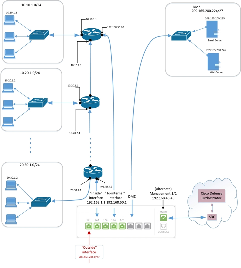
 .
.


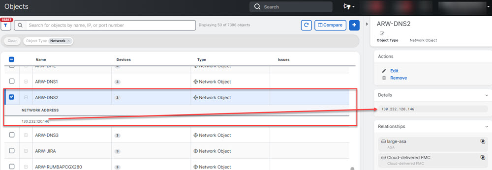
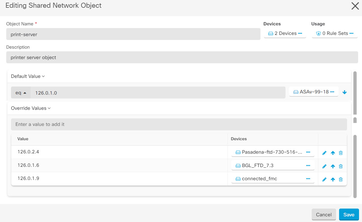
 and check the Unassociated checkbox.
 .
.
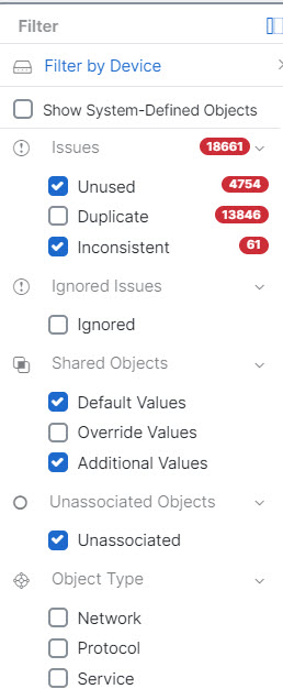
 .
.
 appearing beside the object name or network group to modify them.
 arrow in
  arrow in


 .
.
 in the
  button.
 ) button to refresh the table that shows threats based on the current search filters.
 ) button to download the current summary of the threats to a comma-separated value (.csv) file. You can open the .csv file
in a spreadsheet application such as Microsoft Excel to sort and filter the items on your list.
) button to download the current summary of the threats to a comma-separated value (.csv) file. You can open the .csv file
in a spreadsheet application such as Microsoft Excel to sort and filter the items on your list.  badge indicates the overrides are inconsistent across the devices. You can see the INCONSISTENT field with the number of
devices affected:
badge indicates the overrides are inconsistent across the devices. You can see the INCONSISTENT field with the number of
devices affected: 

 button, review the descriptions of passive and active authentication and click

 . You can also download the certificate used with decrypt re-sign
rules so that you can distribute it to clients. See the following
sections of the Security Policies chapter in the
. You can also download the certificate used with decrypt re-sign
rules so that you can distribute it to clients. See the following
sections of the Security Policies chapter in the  to obtain a copy. See the documentation for each browser for information on how to install the certificate. Also see
  . The priority can be set when the device is not attached to the ruleset. This selection affects all of the rules included
in this ruleset and how it is handled on the devices:
. The priority can be set when the device is not attached to the ruleset. This selection affects all of the rules included
in this ruleset and how it is handled on the devices:
 icon from the top right corner of the screen.
 appearing beside
  button appearing in the upper right corner of the window.
 .
.
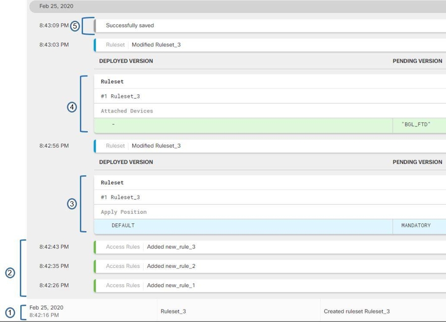
 icon appearing on the top right corner of a ruleset.

 .
.
 .
.

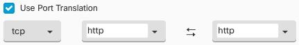
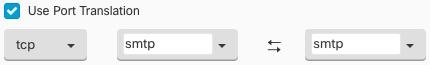


 button and enter the appropriate pre-shared keys for the devices.


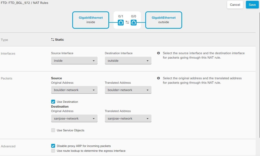

 and look in the Peers pane at the right. One peer name will be listed.
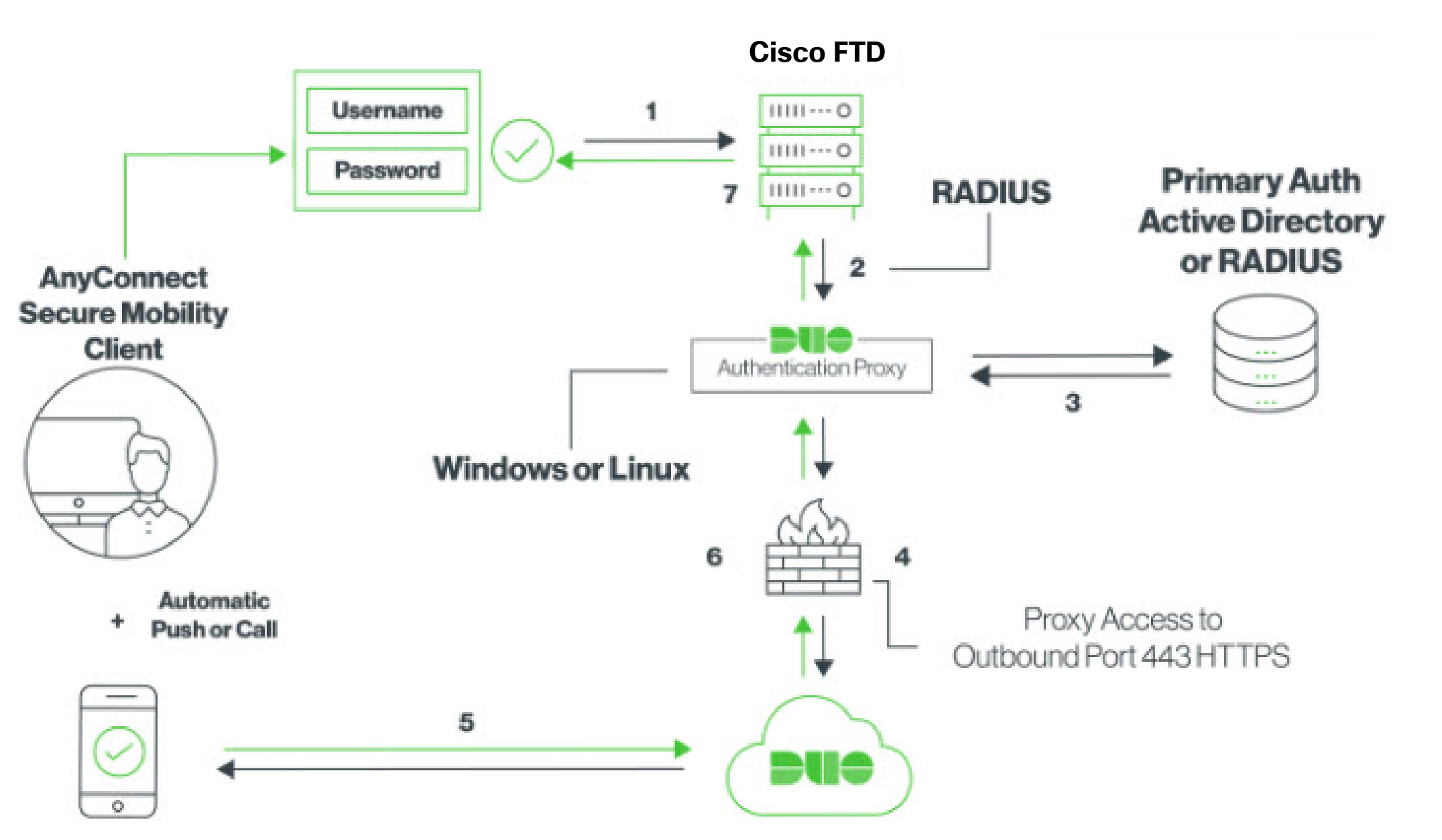


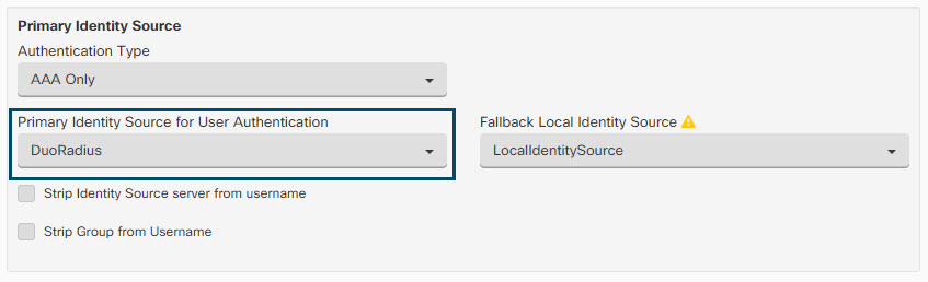

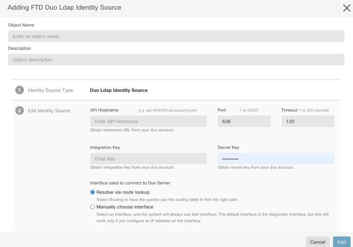


 to upload the package. If the checksum doesn't match, the AnyConnect package upload fails. You can see the device's workflow
tab for more details about the failure.
to upload the package. If the checksum doesn't match, the AnyConnect package upload fails. You can see the device's workflow
tab for more details about the failure.
 to upload the package.
  icon appearing beside the existing AnyConnect package. If there are multiple versions of AnyConnect package for an operating
system, select the package you want to replace from the list and click
icon appearing beside the existing AnyConnect package. If there are multiple versions of AnyConnect package for an operating
system, select the package you want to replace from the list and click  icon appearing beside the AnyConnect package that you want to delete. If there are multiple versions of AnyConnect package
for an operating system, select the package you want to delete from the list. The existing package disappears from the corresponding
field.
icon appearing beside the AnyConnect package that you want to delete. If there are multiple versions of AnyConnect package
for an operating system, select the package you want to delete from the list. The existing package disappears from the corresponding
field.
 to perform the following on the
  to copy the instructions to the clipboard, and then distribute them to your users.
 ) button (
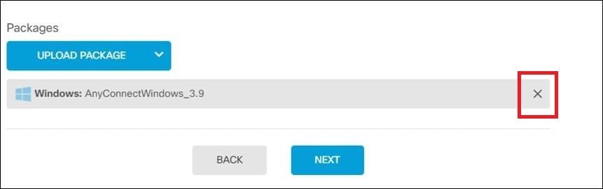
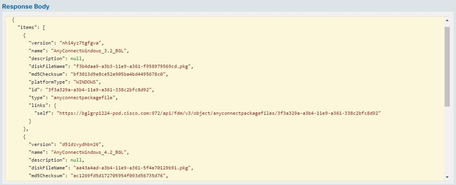
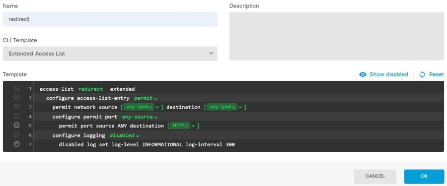

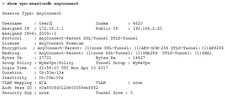
 ) to open a summary of the connection profile and connection instructions. Under
  located to the right of the columns and select or deselect the columns you want.
 icon on the top right corner.

 .
.

 to expand the history pane if it is not already expanded.
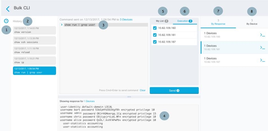


 to see what macros already exist.
 . The command is now the basis for a new CLI macro.

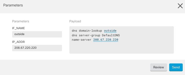

 .
.


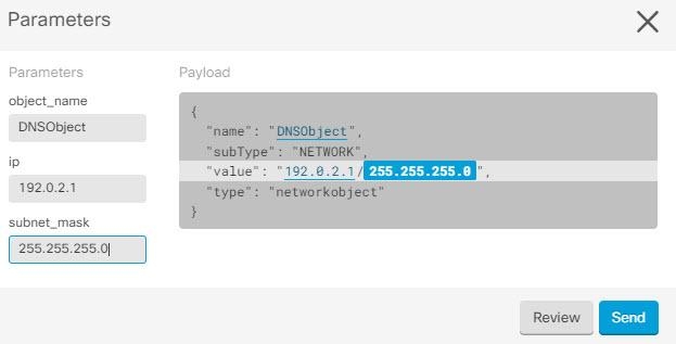
 .
.
 on the details pane. Review any warnings and click
  in the navigation bar to view the results of the bulk deploy.

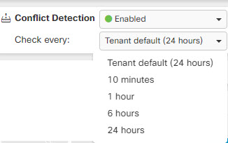
 Feedback