Unicast Overlay Routing

The overlay network is controlled by the Cisco SD-WAN Overlay Management Protocol (OMP), which is at the heart of Cisco SD-WAN overlay routing. This solution allows the building of scalable, dynamic, on-demand, and secure VPNs. The Cisco SD-WAN solution uses a centralized controller for easy orchestration, with full policy control that includes granular access control and a scalable secure data plane between all edge nodes.

The Cisco SD-WAN solution allows edge nodes to communicate directly over any type of transport network, whether public WAN, internet, metro Ethernet, MPLS, or anything else.

Supported Protocols

This section explains the protocols supported for unicast routing.

OMP Routing Protocol

The Cisco SD-WAN Overlay Management Protocol (OMP) is the protocol responsible for establishing and maintaining the Cisco SD-WAN control plane. It provides the following services:

  • Orchestration of overlay network communication, including connectivity among network sites, service chaining, and VPN or VRF topologies

  • Distribution of service-level routing information and related location mappings

  • Distribution of data plane security parameters

  • Central control and distribution of routing policy

OMP is the control protocol that is used to exchange routing, policy, and management information between Cisco vSmart Controllers and Cisco IOS XE SD-WAN devices in the overlay network. These devices automatically initiate OMP peering sessions between themselves, and the two IP end points of the OMP session are the system IP addresses of the two devices.

OMP is an all-encompassing information management and distribution protocol that enables the overlay network by separating services from transport. Services provided in a typical VRF setting are usually located within a VRF domain, and they are protected so that they are not visible outside the VRF. In such a traditional architecture, it is a challenge to extend VRF domains and service connectivity.

OMP addresses these scalability challenges by providing an efficient way to manage service traffic based on the location of logical transport end points. This method extends the data plane and control plane separation concept from within routers to across the network. OMP distributes control plane information along with related policies. A central Cisco vSmart Controller makes all decisions related to routing and access policies for the overlay routing domain. OMP is then used to propagate routing, security, services, and policies that are used by edge devices for data plane connectivity and transport.

OMP Route Advertisements

On Cisco vSmart Controllers and Cisco IOS XE SD-WAN devices, OMP advertises to its peers the routes and services that it has learned from its local site, along with their corresponding transport location mappings, which are called TLOCs. These routes are called OMP routes or vRoutes to distinguish them from standard IP routes. The routes advertised are actually a tuple consisting of the route and the TLOC associated with that route. It is through OMP routes that the Cisco vSmart Controllers learn the topology of the overlay network and the services available in the network.

OMP interacts with traditional routing at local sites in the overlay network. It imports information from traditional routing protocols, such as OSPF and BGP, and this routing information provides reachability within the local site. The importing of routing information from traditional routing protocols is subject to user-defined policies.

Because OMP operates in an overlay networking environment, the notion of routing peers is different from a traditional network environment. From a logical point of view, the overlay environment consists of a centralized controller and a number of edge devices. Each edge device advertises its imported routes to the centralized controller and based on policy decisions, this controller distributes the overlay routing information to other edge devices in the network. Edge devices never advertise routing information to each other, either using OMP or any other method. The OMP peering sessions between the centralized controller and the edge devices are used exclusively to exchange control plane traffic; they are never, in any situation, used for data traffic.

Registered edge devices automatically collect routes from directly connected networks as well as static routes and routes learned from IGP protocols. The edge devices can also be configured to collect routes learned from BGP.

Route map AS path and community configuration, for example, AS path prepend, are not supported when route-maps are configured for protocol redistribution. The AS path for redistributed OMP routes can be configured and applied by using a route map on the BGP neighbor outbound policy.

OMP performs path selection, loop avoidance, and policy implementation on each local device to decide which routes are installed in the local routing table of any edge device.

OMP advertises the following types of routes:

  • OMP routes (also called vRoutes)—Prefixes that establish reachability between end points that use the OMP-orchestrated transport network. OMP routes can represent services in a central data center, services at a branch office, or collections of hosts and other end points in any location of the overlay network. OMP routes require and resolve into TLOCs for functional forwarding. In comparison with BGP, an OMP route is the equivalent of a prefix carried in any of the BGP AFI/SAFI fields.

  • Transport locations (TLOCs)—Identifiers that tie an OMP route to a physical location. The TLOC is the only entity of the OMP routing domain that is visible to the underlying network, and it must be reachable via routing in the underlying network. A TLOC can be directly reachable via an entry in the routing table of the physical network, or it must be represented by a prefix residing on the outside of a NAT device and must be included in the routing table. In comparison with BGP, the TLOC acts as the next hop for OMP routes.

The following figure illustrates the two types of OMP routes.

OMP Routes

Each device at a branch or local site advertises OMP routes to the Cisco vSmart Controllers in its domain. These routes contain routing information that the device has learned from its site-local network.

A Cisco SD-WAN device can advertise one of the following types of site-local routes:

  • Connected (also known as direct)

  • Static

  • BGP

  • EIGRP

  • LISP

  • OSPF (inter-area, intra-area, and external)

OMP routes advertise the following attributes:

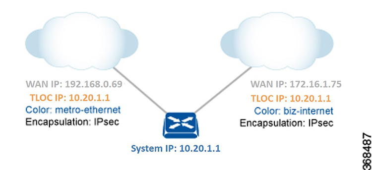
  • TLOC—Transport location identifier of the next hop for the vRoute. It is similar to the BGP NEXT_HOP attribute. A TLOC consists of three components:

    • System IP address of the OMP speaker that originates the OMP route

    • Color to identify the link type

    • Encapsulation type on the transport tunnel

  • Origin—Source of the route, such as BGP, OSPF, connected, and static, and the metric associated with the original route.

  • Originator—OMP identifier of the originator of the route, which is the IP address from which the route was learned.

  • Preference—Degree of preference for an OMP route. A higher preference value is more preferred.

  • Site ID—Identifier of a site within the Cisco SD-WAN overlay network domain to which the OMP route belongs.

  • Tag—Optional, transitive path attribute that an OMP speaker can use to control the routing information it accepts, prefers, or redistributes.

  • VRF—VRF or network segment to which the OMP route belongs.

You configure some of the OMP route attribute values, including the system IP, color, encapsulation type, carrier, preference, service, site ID, and VRF. You can modify some of the OMP route attributes by provisioning control policy on the Cisco vSmart Controller.

TLOC Routes

TLOC routes identify transport locations. These are locations in the overlay network that connect to physical transport, such as the point at which a WAN interface connects to a carrier. A TLOC is denoted by a 3-tuple that consists of the system IP address of the OMP speaker, a color, and an encapsulation type. OMP advertises each TLOC separately.

TLOC routes advertise the following attributes:

  • TLOC private address—Private IP address of the interface associated with the TLOC.

  • TLOC public address—NAT-translated address of the TLOC.

  • Carrier—An identifier of the carrier type, which is generally used to indicate whether the transport is public or private.

  • Color—Identifies the link type.

  • Encapsulation type—Tunnel encapsulation type.

  • Preference—Degree of preference that is used to differentiate between TLOCs that advertise the same OMP route.

  • Site ID—Identifier of a site within the Cisco SD-WAN overlay network domain to which the TLOC belongs.

  • Tag—Optional, transitive path attribute that an OMP speaker can use to control the flow of routing information toward a TLOC. When an OMP route is advertised along with its TLOC, both or either can be distributed with a community TAG, to be used to decide how send traffic to or receive traffic from a group of TLOCs.

  • Weight—Value that is used to discriminate among multiple entry points if an OMP route is reachable through two or more TLOCs.

The IP address used in the TLOC is the fixed system address of the device itself. The reason for not using an IP address or an interface IP address to denote a TLOC is that IP addresses can move or change; for example, they can be assigned by DHCP, or interface cards can be swapped. Using the system IP address to identify a TLOC ensures that a transport end point can always be identified regardless of IP addressing.

The link color represents the type of WAN interfaces on a device. The Cisco SD-WAN solution offers predefined colors, which are assigned in the configuration of the devices. The color can be one of default, 3g, biz-internet, blue, bronze, custom1, custom2, custom3, gold, green, lte, metro-ethernet, mpls, private1, private2, public-internet, red, and silver.

The encapsulation is that used on the tunnel interface. It can be either IPsec or GRE.

The diagram to the right shows a device that has two WAN connections and hence two TLOCs. The system IP address of the router is 1.1.1.1. The TLOC on the left is uniquely identified by the system IP address 1.1.1.1, the color metro-ethernet, and the encapsulation IPsec, and it maps to the physical WAN interface with the IP address 184.168.0.69. The TLOC on the right is uniquely identified by the system IP address 1.1.1.1, the color biz-internet, and the encapsulation IPsec, and it maps to the WAN IP address 75.1.1.1.

You configure some of the TLOC attributes, including the system IP address, color, and encapsulation, and you can modify some of them by provisioning control policy on the Cisco vSmart Controller. See Centralized Control Policy.

OMP Route Redistribution

OMP automatically redistributes the following types of routes that it learns either locally or from its routing peers:

  • Connected

  • Static

  • OSPF intra-area routes

  • OSPF inter-area routes

To avoid routing loops and less than optimal routing, redistribution of following types of routes requires explicit configuration:

  • BGP

  • OSPF external routes

To avoid propagating excessive routing information from the edge to the access portion of the network, the routes that devices receive via OMP are not automatically redistributed into the other routing protocols running on the routers. If you want to redistribute the routes received via OMP, you must enable this redistribution locally on each device.

OMP sets the origin and sub-origin type in each OMP route to indicate the route's origin (see the table below). When selecting routes, the Cisco vSmart Controllerand the router take the origin type and subtype into consideration.

Table 1.

OMP Route Origin Type

OMP Route Origin Subtype

BGP

External Internal

Connected

OSPF

External-1 External-2 Intra-area Inter-area and NSSA-External-1, NSSA-External-2

Static

EIGRP

  • EIGRP Summary

  • EIGRP Internal

  • EIGRP External

LISP

OMP also carries the metric of the original route. A metric of 0 indicates a connected route.

Administrative Distance

Administrative distance is the measure used to select the best path when there are two or more different routes to the same destination from multiple routing protocols. When the Cisco vSmart Controller or the router is selecting the OMP route to a destination, it prefers the one with the lower or lowest administrative distance value.

The following table lists the default administrative distances used by the Cisco SD-WAN devices:

Table 2.

Protocol

Administrative Distance

Connected

0

Static

1

NAT (NAT and static routes cannot coexist in the same VPN; NAT overwrites static routes)

1

Learned from DHCP

1

GRE

5

EBGP

20

OSPF

110

IBGP

200

OMP

250

EIGRP

Internal: 90, External: 170

OMP Best-Path Algorithm and Loop Avoidance

Cisco SD-WAN devices advertise their local routes to the Cisco vSmart Controller using OMP. Depending on the network topology, some routes might be advertised from multiple devices. Cisco SD-WAN devices use the following algorithm to choose the best route:

  1. Select an ACTIVE route. An ACTIVE route is preferred over a STALE route. An active route is a route from a peer with which an OMP session is UP. A stale route is a route from a peer with which an OMP session is in Graceful Restart mode.

  2. Check whether the OMP route is valid. If not, ignore it.

  3. If the OMP route is valid and if it has been learned from the same Cisco SD-WAN device, select the OMP route with the lower administrative distance.

  4. If the administrative distances are equal, select the OMP route with the higher OMP route preference value.

  5. If the TLOC preference values are equal, compare the origin type, and select one in the following order (select the first match): Connected Static EBGP OSFP intra-area OSPF inter-area OSPF external EIGRP internal EIGRP external IBGP Unknown

  6. If the origin type is the same, select the OMP route that has the lower origin metric.

  7. If the router IDs are equal, a Cisco IOS XE SD-WAN device selects the OMP route with the lower private IP address. If a Cisco vSmart Controller receives the same prefix from two different sites and if all attributes are equal, it chooses both of them.

Here are some examples of choosing the best route:

  • A Cisco vSmart Controller receives an OMP route to 10.10.10.0/24 via OMP from a Cisco vEdge device Cisco IOS XE SD-WAN device with an origin code of OSPF, and it also receives the same route from another Cisco vSmart Controller, also with an origin code of OSPF. If all other things are equal, the best-path algorithm chooses the route that came from the Cisco IOS XE SD-WAN device.

  • A Cisco vSmart Controller learns the same OMP route, 10.10.10.0/24, from two Cisco IOS XE SD-WAN devicesin the same site. If all other parameters are the same, both routes are chosen and advertised to other OMP peers. By default, up to four equal-cost routes are selected and advertised.

A Cisco IOS XE SD-WAN device installs an OMP route in its forwarding table (FIB) only if the TLOC to which it points is active. For a TLOC to be active, an active BFD session must be associated with that TLOC. BFD sessions are established by each device which creates a separate BFD session with each of the remote TLOCs. If a BFD session becomes inactive, the Cisco vSmart Controller removes from the forwarding table all the OMP routes that point to that TLOC.

OMP Graceful Restart

Graceful restart for OMP allows the data plane in the Cisco SD-WAN overlay network to continue functioning if the control plane stops functioning or becomes unavailable. With graceful restart, if the vSmart controller in the network goes down, or if multiple vSmart controllers go down simultaneously, Cisco IOS XE SD-WAN devices and Cisco vEdge devices can continue forwarding data traffic. They do this using the last known good information that they received from the vSmart controller. When a vSmart controller is again available, its DTLS connection to the device is re-established, and the device then receives updated, current network information from the vSmart controller.

When OMP graceful restart is enabled, Cisco IOS XE SD-WAN devices and Cisco vEdge devicesand a vSmart controller (that is, two OMP peers) cache the OMP information that they learn from their peer. This information includes OMP routes, TLOC routes, service routes, IPsec SA parameters, and centralized data policies. When one of the OMP peers is no longer available, the other peer uses the cached information to continue operating in the network. So, for example, when a device no longer detects the presence of the OMP connection to a vSmart controller, the device continues forwarding data traffic using the cached OMP information. The device also periodically checks whether the vSmart controller has again become available. When it does come back up and the device re-establishes a connection to it, the device flushes its local cache and considers only the new OMP information from the vSmart controller to be valid and reliable. This same scenario occurs when a vSmart controller no longer detects the presence of Cisco IOS XE SD-WAN devices and Cisco vEdge devices.

BGP and OSPF Routing Protocols

The Cisco SD-WAN overlay network supports BGP and OSPF unicast routing protocols. These protocols can be configured on Cisco IOS XE SD-WAN devices in any VRF except for transport and management VRFs to provide reachability to networks at their local sites. Cisco IOS XE SD-WAN device can redistribute route information learned from BGP and OSPF into OMP so that OMP can better choose paths within the overlay network.

When the local site connects to a Layer 3 VPN MPLS WAN cloud, the devices act as an MPLS CE device and establishes a BGP peering session to connect to the PE router in the L3VPN MPLS cloud.

When the devices at a local site do not connect directly to the WAN cloud but are one or more hops from the WAN and connect indirectly through a non-Cisco SD-WAN device, standard routing must be enabled on the devices’ DTLS connections so that they can reach the WAN cloud. Either OSPF or BGP can be the routing protocol.

In both these types of topologies, the BGP or OSPF sessions run over a DTLS connection created on the loopback interface in VRF 0, which is the transport VRF that is responsible for carrying control traffic in the overlay network. The Cisco vBond Orchestrator learns about this DTLS connection via the loopback interface and conveys this information to the Cisco vSmart Controller so that it can track the TLOC-related information. In VRF 0, you also configure the physical interface that connects the Cisco IOS XE SD-WAN device to its neighbor—either the PE router in the MPLS case or the hub or next-hop router in the local site—but you do not establish a DTLS tunnel connection on that physical interface.

BGP Community Propagation

Table 3. Feature History

Feature Name

Release Information

Description

BGP Community Propagation

Cisco IOS XE Release 17.3.1a

Cisco vManage Release 20.3.1

This feature enables propagation of BGP communities between routing protocols during route redistribution. One one node, the OMP redistributes routes from BGP and on the other node, the OMP redistributes node into BGP. The BGP AS Path is propagated over OMP so that it can be preserved between Cisco SD-WAN nodes. The BGP community propagation helps in propagating BGP communities between Cisco SD-WAN sites, across VPNs using OMP redistribution.

Starting from Cisco IOS XE Release 17.3.1a, the community propagation feature is supported. Without this option, no BGP communities are sent to the BGP neighbor, even if they are attached. With this feature, the Cisco IOS XE SD-WAN device can start propagating the communities attached to the BGP entries to the neighbor. The BGP overlay is migrated to a Cisco-SDWAN overlay where BGP route attributes are propagated between Cisco SD-WAN sites across VPNs.

EIGRP

Cisco EIGRP (Enhanced Interior Gateway Routing Protocol) is a Cisco proprietary routing protocol. It is an open-standard Interior Gateway Protocol (IGP). EIGRP is an enhancement to the original Interior Gateway Routing Protocol (IGRP developed) by Cisco. EIGRP does not fully update if there are no changes in the network. This reduces the flooding activities in other IGPs. It also can use both equal cost and unequal cost paths, which is unique among IGPs.

EIGRP is supported only on Cisco IOS XE SD-WAN devices.

See Introduction to EIGRP for more information in EIGRP.


Note

If your EIGRP network includes Cisco vEdge devices, you may need additional software. Refer to Cisco IOS XE SD-WAN Release 16.11.x and Cisco SD-WAN Release 19.1.x release notes for configuration information.

Benefits of EIGRP

  • Increased network width from 15 to 100 hops

  • Fast convergence

  • Incremental updates, minimizing bandwidth

  • Protocol-independent neighbor discovery

  • Easy scaling

Limitations and Restrictions

  • EIGRP is not supported on the transport side network on Cisco IOS XE SD-WAN devices.

  • EIGRP route match is not supported in vSmart centralized control policy.

Configure Unicast Overlay Routing

This topic describes how to provision unicast overlay routing.

Transport-Side Routing

To enable communication between Cisco SD-WAN devices, you configure OSPF or BGP on a loopback interface in VPN 0. The loopback interface is a virtual transport interface that is the terminus of the DTLS and IPsec tunnel connections required for Cisco IOS XE SD-WAN devices and Cisco vEdge devices to participate in the overlay network.

To configure transport-side BGP using vManage, see the Configure BGP using vManage . To configure transport-side BGP using CLI, see the Configure BGP Using CLI topic.

Configure BGP Using vManage Templates

The Border Gateway Protocl (BGP) can be used for service-side routing to provide reachability to networks at the local site, and it can be used for transport-side routing to enable communication between Cisco SD-WAN devices when a device is not directly connected to the WAN cloud. Create separate BGP templates for the two BGP routing types.


Note

Cisco IOS XE SD-WAN devices use VRFs in place of VPNs. However, the following steps still apply to configure Cisco IOS XE SD-WAN devices through Cisco vManage. When you complete the configuration, the system automatically maps the VPN configurations to VRF configurations.


To configure the BGP routing protocol using Cisco vManage templates:

  1. Create a BGP feature template to configure BGP parameters.

  2. Create a VPN feature template to configure VPN parameters for either service-side BGP routing (in any VPN other than VPN 0 or VPN 512) or transport-side BGP routing (in VPN 0).

Create a BGP Template

  1. In vManage, go to Configuration > Templates.

  2. In the Device tab, click Create Template.

  3. From the Create Template drop-down, select From Feature Template.

  4. From the Device Model drop-down, select the type of device for which you are creating the template.

  5. To create a template for VPN 0 or VPN 512:

    1. Click the Transport & Management VPN tab located directly beneath the Description field, or scroll to the Transport & Management VPN section.

    2. Under Additional VPN 0 Templates, located to the right of the screen, click BGP.

    3. From the BGP drop-down, click Create Template. The BGP template form displays. The top of the form contains fields for naming the template, and the bottom contains fields for defining BGP parameters.

  6. To create a template for VPNs 1 through 511, and 513 through 65530:

    1. Click the Service VPN tab located directly beneath the Description field, or scroll to the Service VPN section.

    2. Click the Service VPN drop-down.

    3. Under Additional VPN Templates, located to the right of the screen, click BGP.

    4. From the BGP drop-down, click Create Template. The BGP template form displays. The top of the form contains fields for naming the template, and the bottom contains fields for defining BGP parameters.

  7. In the Template Name field, enter a name for the template. The name can be up to 128 characters and can contain only alphanumeric characters.

  8. In the Template Description field, enter a description of the template. The description can be up to 2048 characters and can contain only alphanumeric characters.

Configure Basic BGP Parameters

To configure Border Gateway Protocol (BGP), select the Basic Configuration tab and configure the following parameters. Parameters marked with an asterisk are required to configure BGP.

Parameter Name Description
Shutdown* Click No to enable BGP on the interface.
AS number* Enter the local AS number.
Router ID Enter the BGP router ID in decimal four-part dotted notation.
Propagate AS Path Click On to carry BGP AS path information into OMP.
Internal Routes Distance

Enter a value to apply as the BGP route administrative distance for routes coming from one AS into another.

Range: 0 through 255

Default: 0

Local Routes Distance Specify the BGP route administrative distance for routes within the local AS. By default, a route received locally from BGP is preferred over a route received from OMP.

Range: 0 through 255

Default: 0

External Routes Distance Specify the BGP route administrative distance for routes learned from other sites in the overlay network.

Range: 0 through 255

Default: 0

For service-side BGP, you might want to configure Overlay Management Protocol (OMP) to advertise to the Cisco vSmart Controller any BGP routes that the device learns. By default, Cisco SD-WAN devices advertise to OMP both the connected routes on the device and the static routes that are configured on the device, but it does not advertise BGP external routes learned by the device. You configure this route advertisement in the OMP template for devices or Cisco SD-WAN software.

For transport-side BGP, you must also configure a physical interface and a loopback interface in VPN 0. In addition, you should create a policy for BGP to advertise the loopback interface address to its neighbors, and apply the policy in the BGP instance or to a specific neighbor.

To save the feature template, click Save.

Configure Unicast Address Family

To configure global BGP address family information, select the IPv4 Unicast Address Family tab and configure the following parameters:

Tab/Parameter Option Sub-Option Description
IPv4 / IPv6 Click IPv4 to configure an IPv4 VPN interface. Click IPv6 to configure an IPv6 interface.
Maximum Paths

Specify the maximum number of parallel IBGP paths that can be installed into a route table to enable IBGP multipath load sharing.

Range: 0 to 32

Mark as Optional Row Check Mark as Optional Row to mark this configuration as device-specific. To include this configuration for a device, enter the requested variable values when you attach a device template to a device, or create a template variables spreadsheet to apply the variables.
Redistribute Click Redistribute > New Redistribute.
Mark as Optional Row Check Mark as Optional Row to mark this configuration as device-specific. To include this configuration for a device, enter the requested variable values when you attach a device template to a device, or create a template variables spreadsheet to apply the variables.
Protocol Select the protocols from which to redistribute routes into BGP, for all BGP sessions. Options are:
static Redistribute static routes into BGP.
connected Redistribute connected routes into BGP.
ospf Redistribute Open Shortest Path First routes into BGP.
omp Redistribute Overlay Management Protocol routes into BGP.
nat Redistribute Network Address Translation routes into BGP.
natpool-outside Redistribute outside NAT routes into BGP.
At a minimum, select the following:
  • For service-side BGP routing, select OMP. By default, OMP routes are not redistributed into BGP.

  • For transport-side BGP routing, select Connected, and then under Route Policy, specify a route policy that has BGP advertise the loopback interface address to its neighbors.

Route Policy Enter the name of the route policy to apply to redistributed routes.
Click Add to save the redistribution information.
Network Click Network > New Network.
Mark as Optional Row Check Mark as Optional Row to mark this configuration as device-specific. To include this configuration for a device, enter the requested variable values when you attach a device template to a device, or create a template variables spreadsheet to apply the variables.
Network Prefix Enter a network prefix, in the format prefix/length to be advertised by BGP.
Click Add to save the network prefix.
Aggregate Address Click Aggregate Address > New Aggregate Address.
Mark as Optional Row Check Mark as Optional Row to mark this configuration as device-specific. To include this configuration for a device, enter the variable values when you attach a device template to a device, or create a template variables spreadsheet to apply the variables.

Aggregate Prefix

IPv6 Aggregate Prefix

Enter the prefix of the addresses to aggregate for all BGP sessions in the format prefix/length.
AS Set Path Click On to generate the set path information for aggregated prefixes.
Summary Only Click On to filter out specific routes from the BGP updates.
Click Add to save the aggregate address.

To save the feature template, click Save.

Configure BGP Neighbors

To configure a neighbor, click Neighbor > New Neighbor, and configure the following parameters:


Note

For BGP to function, you must configure at least one neighbor.


Parameter Name Options Sub-Options Description
IPv4 / IPv6 Click IPv4 to configure IPv4 neighbors. Click IPv6 to configure IPv6 neighbors.
Address/IPv6 Address Specify the IP address of the BGP neighbor.
Description Enter a description of the BGP neighbor.
Remote AS Enter the AS number of the remote BGP peer.
Address Family Click On and select the address family. Enter the address family information. The software supports only the BGP IPv4 unicast address family.
Address Family Select the address family. The software supports only the BGP IPv4 unicast address family.
Maximum Number of Prefixes

Specify the maximum number of prefixes that can be received from the neighbor.

Range: 1 through 4294967295

Default: 0

Threshold Specify the threshold at which to generate a warning message or restart the BGP connection. The threshold is a percentage of the maximum number of prefixes. You can specify either a restart interval or a warning only.
Restart Interval Specify the duration to wait for restarting the BGP connection.Range: 1 through 65535 minutes
Warning Only Click On to display a warning message without restarting the BGP connection.
Route Policy In Click On and specify the name of a route policy that will have the prefixes from the neighbour.
Route Policy Out Click On and specify the name of a route policy that will have the prefixes sent to the neighbour.
Shutdown Click On to enable the connection to the BGP neighbor.

Configure MPLS Interface

Table 4. Feature History
Feature Name

Release

Information

Description

MPLS-BGP Support on the Service Side

Cisco IOS XE Release 17.2.1r

This features allows you to enable support on Multiprotocol Label Switching (MPLS). Multiple Service VPNs use inter autonomous system (AS) BGP labelled path to forward the traffic, which in turn helps scaling the service side VPNs with less control plane signaling.

Label distribution for a given VPN routing and forwarding (VRF) instance on a given device can be handled by Border Gateway Protocol (BGP).

Cisco IOS XE SD-WAN devices support Multiprotocol Label Switching (MPLS) to enable multiple protocol environment. MPLS offers extremely scalable, protocol agnostic, data-carrying mechanism that transfers data packets with assigned labels across the network through virtual links. Extensions of the BGP protocol can be used to manage an MPLS path. The Cisco IOS XE SD-WAN devices also have the capability of BGP MPLS VPN Option B.

The multiple service VPNs use inter autonomous system (AS) BGP labelled path to forward the traffic, that in turn helps scale the service side VPNs with less control plane signaling. MPLS interface is supported only in global VRF.

To configure MPLS interface,

  • Click MPLS Interface.

  • Enter the interface name in the Interface Name field.

  • You can click on + to add more interfaces and save the configuration.

Configure Label Range

The Cisco vManage automatically programs the label space for BGP MPLS. The labels are allocated per VPN. To view the configuration, use the command, show sdwan running-config.

Sample configuration:

Device# show sdwan running-config
Device# mpls label range 100000 1048575 static 16 999
Device# mpls label mode all-vrfs protocol bgp-vpnv4 per-vrf
Device# mpls label mode all-vrfs protocol bgp-vpnv6 per-vrf

Configure Route Targets

You can configure route targets on the Cisco IOS XE SD-WAN devices. Route targets configuration is supported only on eBGP and IPv4 peer devices. All the supported protocols can be redistributed to BGP.

To configure route targets, click Route Targets tab and configure the following parameters:

Tab/Parameter Option Sub-Option Description
IPv4 / IPv6 Click IPv4 to configure route target for IPv4 interfaces. Click IPv6 to configure route target for IPv6 interfaces.
Add VPN Click Add VPN to add VPNs.
VPN ID for IPv4

Specify the VPN ID for IPv4 interface.

Import

Imports routing information from the target VPN extended community.

Export

Exports routing information to the target VPN extended community.

To save the feature template, click Save.

Initially, the devices have default route targets, then you can add additional entries as required.

Configure Advanced Neighbor Parameter

To configure advanced parameters for the neighbor, click Neighbor > Advanced Options.

Parameter Name Description
Next-Hop Self Click On to configure the router to be the next hop for routes advertised to the BGP neighbor.
Send Community Click On to send the local router's BGP community attribute to the BGP neighbor.
Send Extended Community Click On to send the local router's BGP extended community attribute to the BGP neighbor.
Negotiate Capability Click On to allow the BGP session to learn about the BGP extensions that are supported by the neighbor.
Source Interface Address Enter the IP address of a specific interface of the neighbor that BGP is to use for the TCP connection to the neighbor.
Source Interface Name Enter the name of a specific interface of the neighbor that BGP is to use for the TCP connection to the neighbor, in the format ge port/slot.
EBGP Multihop Set the time to live (TTL) for BGP connections to external peers.

Range: 0 to 255

Default: 1

Password Enter a password to use to generate an MD5 message digest. Configuring the password enables MD5 authentication on the TCP connection with the BGP peer. The password is case-sensitive and can be up to 25 characters long. It can contain any alphanumeric characters, including spaces. The first character cannot be a number.
Keepalive Time Specify the frequency at which keepalive messages are advertised to a BGP peer. These messages indicate to the peer that the local router is still active and should be considered available. Specify the keepalive time for the neighbor to override the global keepalive time.

Range: 0 through 65535 seconds

Default: 60 seconds (one-third the hold-time value)

Hold Time Specify the interval after not receiving a keepalive message that the local BGP session considers its peer to be unavailable. The local router then terminates the BGP session to that peer. Specify the hold time for the neighbor to override the global hold time.

Range: 0 through 65535 seconds

Default: 180 seconds (three times the keepalive timer)

Connection Retry Time Specify the number of seconds between retries to establish a connection to a configured BGP neighbor peer that has gone down.

Range: 0 through 65535 seconds

Default: 30 seconds

Advertisement Interval For the BGP neighbor, set the minimum route advertisement interval (MRAI) between when BGP routing update packets are sent to that neighbor.

Range: 0 through 600 seconds

Default: 5 seconds for IBGP route advertisements; 30 seconds for EBGP route advertisements

To save the feature template, click Save.

Change the Scope of a Parameter Value

When you first open a feature template, for each parameter that has a default value, the scope is set to Default (a ), and the default setting or value is shown). To change the default or to enter a value, click the scope drop-down to the left of the parameter field and select one of the following:

Parameter Name

Description

Device Specific

Use a device-specific value for the parameter. For device-specific parameters, you cannot enter a value in the feature template. You enter the value when you attach a device to a device template.

When you click Device Specific, the Enter Key box opens. This box displays a key which is a unique string that identifies the parameter in a CSV file that you create. This file is an Excel spreadsheet that contains one column for each key. The header row contains the key names (one key per column), and each row after that corresponds to a device and defines the values of the keys for that device. You upload the CSV file when you attach a device to a device template.

To change the default key, type a new string and move the cursor out of the Enter Key box.

Examples of device-specific parameters are system IP address, hostname, GPS location, and site ID.

Global

Enter a value for the parameter, and apply that value to all devices.

Examples of parameters that you might apply globally to a group of devices are DNS server, syslog server, and interface MTUs.

Configure Advanced BGP Parameters

To configure advanced parameters for BGP, click the Advanced tab and configure the following parameters:

Parameter Name Description
Hold Time Specify the interval after not receiving a keepalive message that the local BGP session considers its peer to be unavailable. The local device then terminates the BGP session to that peer. This hold time is the global hold time.

Range: 0 through 65535 seconds

Default: 180 seconds (three times the keepalive timer)

Keepalive Specify the frequency at which keepalive messages are advertised to a BGP peer. These messages indicate to the peer that the local device is still active and should be considered available. This keepalive time is the global keepalive time.

Range: 0 through 65535 seconds

Default: 60 seconds (one-third the hold-time value)

Compare MED Click On to compare the device IDs among BGP paths to determine the active path.
Deterministic MED Click On to compare multiple exit discriminators (MEDs) from all routes received from the same AS, regardless of when the route was received.
Missing MED as Worst Click On to consider a path as the worst path if the path is missing a MED attribute.
Compare Router ID Click On to always compare MEDs regardless of whether the peer ASs of the compared routes are the same.
Multipath Relax Click On to have the BGP best-path process select from routes in different in ASs. By default, when you are using BGP multipath, the BGP best path process selects from routes in the same AS to load-balance across multiple paths.

To save the feature, click Save.

Configure BGP Using CLI

This is an example of a BGP configuration on a Cisco IOS XE SD-WAN device.

router bgp 100               
 bgp log-neighbor-changes
 distance bgp 20 200 20
 !
 address-family ipv4 vrf 100   
  bgp router-id 10.0.0.0      
  redistribute omp                               
  neighbor 10.0.0.1 remote-as 200   
  neighbor 10.0.0.1 activate
  neighbor 10.0.0.1 send-community both
  neighbor 10.0.0.1 route-map OMP_BGP-POLICY in    
  neighbor 10.0.0.1 maximum-prefix 2147483647 100


route-map OMP_BGP-POLICY permit 1 
 match ip address prefix-list OMP-BGP-TEST-PREFIX-LIST
 set omp-tag 10000
route-map OMP_BGP-POLICY permit 65535 


ip prefix-list OMP-BGP-TEST-PREFIX-LIST seq 5 permit 10.0.0.0/8

Verify BGP Redistribute Route in OMP


Device#show sdwan omp routes 10.0.0.0/8
---------------------------------------------------
omp route entries for vpn 100 route 10.0.0.0/8
---------------------------------------------------
               RECEIVED FROM:                   
peer            172.16.0.0
path-id         470777
label           1002
status          C,I,R
loss-reason     not set
lost-to-peer    not set
lost-to-path-id not set
    Attributes:
     originator       10.0.0.1     
     type             installed
     tloc             172.16.0.1, mpls, ipsec
     ultimate-tloc    not set
     domain-id        not set
     overlay-id        1
     site-id          1
     preference       not set
     tag              10000   <=====
     origin-proto     eBGP
     as-path          not set
     unknown-attr-len not set

The following example shows the propagation of BGP community on Cisco IOS XE SD-WAN devices:

vm5#show sdwan omp routes 192.168.0.0/16 detail 
---------------------------------------------------
omp route entries for vpn 1 route 192.168.0.0/16---------------------------------------------------
            RECEIVED FROM:                   
peer         10.0.0.0
path-id         70
label           1007
status          C,Red,R
loss-reason     not set
lost-to-peer    not set
lost-to-path-id not set
    Attributes:
     originator       192.168.0.0
     type             installed
     tloc             192.168.0.1, lte, ipsec
     ultimate-tloc    not set
     domain-id        not set
     overlay-id        1
     site-id          500
     preference       not set
     tag              not set
     origin-proto     iBGP
     origin-metric    0
     as-path          not set
     community        100:1 100:2 100:3
     unknown-attr-len not set
            ADVERTISED TO:                   
peer    192.168.0.1

This topic describes how to configure BGP for service-side and transport-side for unicast overlay routing

Configure Service-Side Routing

To set up routing on the Cisco vEdge device, you provision one VPN or multiple VPNs if segmentation is required. Within each VPN, you configure the interfaces that participate in that VPN and the routing protocols that operate in that VPN.

  1. Configure a VPN.

    vEdge(config)# vpn vpn-id
    

    vpn-id can be any service-side VPN, which is a VPN other than VPN 0 and VPN 512. VPN 0 is the transport VPN and carries only control traffic, and VPN 512 is the management VPN.

  2. Configure BGP to run in the VPN:

    1. Configure the local AS number:​

      vEdge(config-vpn)# router bgp local-as-number 

      You can specify the AS number in 2-byte ASDOT notation (1 through 65535) or in 4-byte ASDOT notation (1.0 through 65535.65535).

    2. Configure the BGP peer, specifying its address and AS number (the remote AS number), and enable the connection to the peer:

      vEdge(config-bgp)# neighbor address remote-as remote-as-number
      vEdge(config-bgp)# no shutdown
      
  3. Configure a system IP address for the Cisco vEdge device:

    vEdge(config)# system system-ipaddress
    

Example of BGP Configuration on a SD-WAN IOS XE Router

Device# show running-config system
system
  system-ip 10.1.2.3
!
Device# show running-config vpn 1
router bgp 2
bgp log-neighbor-changes
timers bgp 1 111
neighbor 10.20.25.16 remote-as 1

!
address-family ipv4 unicast
neighbor 10.20.25.16 activate
exit-address-family
!
address-family vpnv4 unicast
neighbor 10.20.25.16 activate
neighbor 10.20.25.16 send-community extended
exit-address-family
!
address-family vpnv6 unicast
neighbor 10.20.25.16 activate
neighbor 10.20.25.16 send-community extended
exit-address-family
!
address-family ipv4 unicast vrf 1
redistribute connected
redistribute static
exit-address-family
!
address-family ipv6 unicast vrf 1
redistribute connected
redistribute omp

exit-address-family
!
address-family ipv4 unicast vrf 2
redistribute connected

exit-address-family

Example of configuring route targets:

vrf config

vrf definition 1
rd 1:1

!
address-family ipv4

route-target export 200:1

route-target import 100:1

exit-address-family
!
address-family ipv6
route-target export 101:1
route-target import 201:1
exit-address-family

Redistribute BGP Routes and AS Path Information

By default, routes from other routing protocols are not redistributed into BGP. It can be useful for BGP to learn OMP routes, because OMP learns routes to destinations throughout the overlay network. BGP on the Cisco SD-WAN devices, then advertises the OMP routes to all the BGP routers in the service-side of the network.


config-transaction
 router bgp 2  
  address-family ipv4 unicast
   redistribute omp route-map route_map

To redistribute OMP routes into BGP so that these routes are advertised to all BGP routers in the service side of the network, configure redistribution in any VRF except transport VRF or Mgmt VRF:

For Cisco IOS XE SD-WAN device, under router BGP configuration, redistribute omp route-map set/match is used instead of redistribute omp metric 0 setting as the redistribute omp metric is disabled in all the branches.

Device(config)# router bgp 100
Device(config-router)# address-family ipv4 vrf 100
Device(config-router-af)# redistribute omp [route-map policy-name]

config-transaction
 router bgp 100  
  address-family ipv4 vrf 100
   redistribute omp route_map route_map

You can also redistribute routes learned from other protocols such as OSPF, rip into BGP, and apply policy as shown in the example above:

You can control redistribution of routes on a per-neighbor basis:


config-transaction
 router bgp 100  
  address-family ipv4 
   neighbor 10.0.100.1 route-map route_map (in | out)
   

You can configure the Cisco IOS XE SD-WAN device to advertise BGP routes that it has learned, through OMP, from the Cisco vSmart Controller. Doing so allows the Cisco vSmart Controller to advertise these routes to other Cisco IOS XE SD-WAN devices in the overlay network. You can advertise BGP routes either globally or for a specific VRF:


config-transaction
 sdwan
  omp
   address-family ipv4 vrf 100
    advertise bgp  
    exit

Configure OSPF Using vManage Templates

Use the OSPF template for all Cisco SD-WAN devices.


Note

Cisco XE SD-WAN devices use VRFs in place of VPNs. However, the following steps still apply to configure Cisco IOS XE SD-WAN devices through Cisco vManage. When you complete the configuration, the system automatically maps the VPN configurations to VRF configurations.


To configure OSPF on a device using Cisco vManage templates:

  1. Create an OSPF feature template to configure OSPF parameters. OSPF can be used for transport-side routing to enable communication between the Cisco SD-WAN devices when the router is not directly connected to the WAN cloud.

  2. Create a VPN feature template to configure VPN parameters for transport-side OSPF routing (in VPN 0). See the VPN help topic for more information.

Create an OSPF Template

  1. In vManage NMS, select Configuration > Templates.

  2. In the Device tab, click Create Template.

  3. From the Create Template drop-down, select From Feature Template.

  4. From the Device Model drop-down, select the type of device for which you are creating the template. To create a template for VPN 0 or VPN 512:

    1. Click the Transport & Management VPN tab located directly beneath the Description field, or scroll to the Transport & Management VPN section.

    2. Under Additional VPN 0 Templates, located to the right of the screen, click OSPF.

    3. From the OSPF drop-down, click Create Template. The OSPF template form is displayed. The top of the form contains fields for naming the template, and the bottom contains fields for defining OSPF parameters.

  5. To create a template for VPNs 1 through 511, and 513 through 65530:

    1. Click the Service VPN tab located directly beneath the Description field, or scroll to the Service VPN section.

    2. Click the Service VPN drop-down.

    3. Under Additional VPN Templates, located to the right of the screen, click OSPF.

    4. From the OSPF drop-down, click Create Template. The OSPF template form is displayed. The top of the form contains fields for naming the template, and the bottom contains fields for defining OSPF parameters.
  6. In the Template Name field, enter a name for the template. The name can be up to 128 characters and can contain only alphanumeric characters.

  7. In the Template Description field, enter a description of the template. The description can be up to 2048 characters and can contain only alphanumeric characters.

When you first open a feature template, for each parameter that has a default value, the scope is set to Default (indicated by a check mark), and the default setting or value is shown. To change the default or to enter a value, click the scope drop-down to the left of the parameter field and select one of the following:

Table 5.

Parameter Scope

Scope Description

Device Specific (indicated by a host icon)

Use a device-specific value for the parameter. For device-specific parameters, you cannot enter a value in the feature template. You enter the value when you attach a Cisco SD-WAN device to a device template .

When you click Device Specific, the Enter Key box opens. This box displays a key,which is a unique string that identifies the parameter in a CSV file that you create. This file is an Excel spreadsheet that contains one column for each key. The header row contains the key names (one key per column), and each row after that corresponds to a device and defines the values of the keys for that device. You upload the CSV file when you attach a Cisco SD-WAN device to a device template. For more information, see Create a Template Variables Spreadsheet .

To change the default key, type a new string and move the cursor out of the Enter Key box.

Examples of device-specific parameters are system IP address, hostname, GPS location, and site ID.

Global (indicated by a globe icon)

Enter a value for the parameter, and apply that value to all devices.

Examples of parameters that you might apply globally to a group of devices are DNS server, syslog server, and interface MTUs.

Configure Basic OSPF

To configure basic OSPF, select the Basic Configuration tab and then configure the following parameters. All these parameters are optional. For OSPF to function, you must configure area 0, as described below.

Table 6.

Parameter Name

Description

Router ID

Enter the OSPF router ID in decimal four-part dotted notation. This is the IP address associated with the router for OSPF adjacencies.

Distance for External Routes

Specify the OSPF route administration distance for routes learned from other domains.

Range: 0 through 255Default: 110

Distance for Inter-Area Routes

Specify the OSPF route administration distance for routes coming from one area into another.

Range: 0 through 255Default: 110

Distance for intra-Area routes

Specify the OSPF route administration distance for routes within an area.

Range: 0 through 255Default: 110

To save the feature template, click Save.

Redistribute Routes into OSPF

To redistribute routes learned from other protocols into OSPF on Cisco SD-WAN devices, select Redistribute > Add New Redistribute and configure the following parameters:

Table 7.

Parameter Name

Description

Protocol

Select the protocol from which to redistribute routes into OSPF. Select from BGP, Connected, NAT, OMP, and Static.

Route Policy

Enter the name of a localized control policy to apply to routes before they are redistributed into OSPF.

To add another OSPF route redistribution policy, click the plus sign (+).

To remove an OSPF route redistribution policy from the template configuration, click the trash icon to the right of the entry.

To save the feature template, click Save.

Configure OSPF To Advertise a Maximum Metric

To configure OSPF to advertise a maximum metric so that other devices do not prefer the Cisco IOS XE SD-WAN device as an intermediate hop in their Shortest Path First (SPF) calculation, select Maximum Metric (Router LSA) > Add New Router LSA and configure the following parameters:

Table 8.

Parameter Name

Description

Type

Select a type:

  • Administrative—Force the maximum metric to take effect immediately through operator intervention.

  • On-Startup—Advertise the maximum metric for the specified time.

Advertisement Time

If you selected On-Startup, specify the number of seconds to advertise the maximum metric after the router starts up.

Range: 0, 5 through 86400 secondsDefault: 0 seconds (the maximum metric is advertised immediately when the router starts up)

To save the feature template, click Save.

Configure OSPF Areas

To configure an OSPF area within a VPN on a Cisco SD-WAN device, select Area > Add New Area. For OSPF to function, you must configure area 0.

Table 9.

Parameter Name

Description

Area Number

Enter the number of the OSPF area.

Range: 32-bit number

Set the Area Type

Select the type of OSPF area, Stub or NSSA.

No Summary

Select On to not inject OSPF summary routes into the area.

Translate

If you configured the area type as NSSA, select when to allow Cisco SD-WAN devices that are ABRs (area border routers) to translate Type 7 LSAs to Type 5 LSAs:

  • Always—Router always acts as the translator for Type 7 LSAs. That is no other router, even if it is an ABR, can be the translator. If two ABRs are configured to always be the translator, only one of them actually ends up doing the translation.

  • Candidate—Router offers translation services, but does not insist on being the translator.

  • Never—Translate no Type 7 LSAs.

To save the new area, click Add.

To save the feature template, click Save.

Configure Interfaces in an OSPF Area

To configure the properties of an interface in an OSPF area, select Area > Add New Area > Add Interface. In the Add Interface popup, configure the following parameters:

Table 10.

Parameter Name

Description

Interface Name

Enter the name of the interface, in the format ge slot/port or loopback number.

Hello Interval

Specify how often the router sends OSPF hello packets.

Range: 1 through 65535 secondsDefault: 10 seconds

Dead Interval

Specify how often the Cisco IOS XE SD-WAN device must receive an OSPF hello packet from its neighbor. If no packet is received, the Cisco IOS XE SD-WAN deviceassumes that the neighbor is down.

Range: 1 through 65535 secondsDefault: 40 seconds (4 times the default hello interval)

LSA Retransmission Interval

Specify how often the OSPF protocol retransmits LSAs to its neighbors.

Range: 1 through 65535 secondsDefault: 5 seconds

Interface Cost

Specify the cost of the OSPF interface.

Range: 1 through 65535

To configure advanced options for an interface in an OSPF area, in the Add Interface popup, click Advanced Options and configure the following parameters:

Table 11.

Parameter Name

Description

Designated Router Priority

Set the priority of the router to be elected as the designated router (DR). The router with the highest priority becomes the DR. If the priorities are equal, the node with the highest router ID becomes the DR or the backup DR.Range: 0 through 255Default: 1

OSPF Network Type

Select the OSPF network type to which the interface is to connect:

  • Broadcast network—WAN or similar network.

  • Point-to-point network—Interface connects to a single remote OSPF router.

Default: Broadcast

Passive Interface

Select On or Off to specify whether to set the OSPF interface to be passive. A passive interface advertises its address, but does not actively run the OSPF protocol.Default: Off

Authentication

Specify the authentication and authentication key on the interface to allow OSPF to exchange routing update information securely.

• Authentication Type

Select the authentication type:

  • Simple authentication—Password is sent in clear text.

  • Message-digest authentication—MD5 algorithm generates the password.

• Authentication Key

Enter the authentication key. Plain text authentication is used when devices within an area cannot support the more secure MD5 authentication. The key can be 1 to 32 characters.

Message Digest

Specify the key ID and authentication key if you are using message digest (MD5).

• Message Digest Key ID

Enter the key ID for message digest (MD5 authentication). It can be 1 to 32 characters.

• Message Digest Key

Enter the MD5 authentication key in clear text or as an AES-encrypted key. It can be from 1 to 255 characters.

To save the interface configuration, click Save.

To save the new area, click Add.

To save the feature template, click Save.

Configure an Interface Range for Summary LSAs

To configure the properties of an interface in an OSPF area, select Area > Add New Area > Add Range. In the Area Range popup, click Add Area Range, and configure the following parameters:

Table 12.

Parameter Name

Description

Address

Enter the IP address and subnet mask, in the format prefix/length for the IP addresses to be consolidated and advertised.

Cost

Specify a number for the Type 3 summary LSA. OSPF uses this metric during its SPF calculation to determine the shortest path to a destination.Range: 0 through 16777215

No Advertise

Select On to not advertise the Type 3 summary LSAs or Off to advertise them.

To save the area range, click Save.

To save the new area, click Add.

To save the feature template, click Save.

Configure Other OSPF Properties

To configure other OSPF properties, select the Advanced tab and configure the following properties:

Table 13.

Parameter Name

Description

Reference Bandwidth

Specify the reference bandwidth for the OSPF auto-cost calculation for the interface.

Range: 1 through 4294967 MbpsDefault: 100 Mbps

RFC 1538 Compatible

By default, the OSPF calculation is done per RFC 1583. Select Off to calculate the cost of summary routes based on RFC 2328.

Originate

Click On to generate a default external route into an OSPF routing domain:

  • Always—Select On to always advertise the default route in an OSPF routing domain.

  • Default metric—Set the metric used to generate the default route.Range: 0 through 16777214Default: 10

  • Metric type—Select to advertise the default route as an OSPF Type 1 external route or an OSPF Type 2 external route.

SPF Calculation Delay

Specify the amount of time between when the first change to a topology is received until performing the SPF calculation.

Range: 0 through 600000 milliseconds (60 seconds)Default: 200 milliseconds

Initial Hold Time

Specify the amount of time between consecutive SPF calculations.

Range: 0 through 600000 milliseconds (60 seconds)Default: 1000 milliseconds

Maximum Hold Time

Specify the longest time between consecutive SPF calculations.

Range: 0 through 600000Default: 10000 milliseconds (60 seconds)

Policy Name

Enter the name of a localized control policy to apply to routes coming from OSPF neighbors.

To save the feature template, click Save.

Configure OSPF Using CLI

This topic describes how to configure basic service-side OSPF for Unicast overlay routing.

Configure Basic Service-Side OSPF

To set up routing on the Cisco IOS XE SD-WAN device, you provision VRFs if segmentation is required. Within each VRF, you configure the interfaces that participate in that VRF and the routing protocols that operate in that VRF.

Here is an example of configuring service-side OSPF on a Cisco IOS XE SD-WAN device.

config-transaction
 router ospf 1 vrf1  
  auto-cost reference-bandwidth 100  
  max-metric router-lsa 
  timers throttle spf 200 1000 10000
  router-id 172.16.255.15
  default-information originate
  distance ospf external 110
  distance ospf inter-area110
  distance ospf intra-area110
  distredistribute connected subnets route-map route_map
  exit
 interface GigabitEthernet0/0/1
  no shutdown
  arp timeout 1200
  vrf forwarding 1
  ip address 10.1.100.14 255.255.255.0
  ip redirects
  ip mtu 1500
  ip ospf 1 area 23  
  ip ospf network broadcast  
  mtu 1500
  negotiation auto
  exit

Configure OMP Using vManage Templates

Use the OMP template to configure OMP parameters for all Cisco IOS XE SD-WAN devices, and for Cisco vSmart Controllers.

OMP is enabled by default on all Cisco IOS XE SD-WAN devices, Cisco vManage NMSs, and Cisco vSmart Controllers, so there is no need to explicitly enable OMP. OMP must be operational for the Cisco SD-WAN overlay network to function. If you disable it, you disable the overlay network.


Note

  • Route advertisements in OMP are done either by applying the configuration at the global level or at the specific VRF level. See the Configure OMP Advertisements section in this topic.

  • Cisco XE SD-WAN devices use VRFs in place of VPNs. However, the following steps still apply to configure Cisco IOS XE SD-WAN devicesthrough Cisco vManage. When you complete the configuration, the system automatically maps the VPN configurations to VRF configurations.


Create OMP Template

  1. In Cisco vManage, select Configuration > Templates.

  2. In the Device tab, click Create Template.

  3. From the Create Template drop-down, select From Feature Template.

  4. From the Device Model drop-down, select the type of device for which you are creating the template.

  5. To create a custom template for OMP, select the Factory_Default_OMP_Template and click Create Template. The OMP template form is displayed. The top of the form contains fields for naming the template, and the bottom contains fields for defining OMP parameters. You may need to click a tab or the plus sign (+) to display additional fields.

  6. In the Template Name field, enter a name for the template. The name can be up to 128 characters and can contain only alphanumeric characters.

  7. In the Template Description field, enter a description of the template. The description can be up to 2048 characters and can contain only alphanumeric characters.

When you first open a feature template, for each parameter that has a default value, the scope is set to Default (indicated by a check mark), and the default setting or value is shown. To change the default or to enter a value, click the scope drop-down to the left of the parameter field and select one of the following:

Table 14.

Parameter Scope

Scope Description

Device Specific (indicated by a host icon)

Use a device-specific value for the parameter. For device-specific parameters, you cannot enter a value in the feature template. You enter the value when you attach a Cisco SD-WAN device to a device template .

When you click Device Specific, the Enter Key box opens. This box displays a key, which is a unique string that identifies the parameter in a CSV file that you create. This file is an Excel spreadsheet that contains one column for each key. The header row contains the key names (one key per column), and each row after that corresponds to a device and defines the values of the keys for that device. You upload the CSV file when you attach a Cisco SD-WAN device to a device template. For more information, see Create a Template Variables Spreadsheet .

To change the default key, type a new string and move the cursor out of the Enter Key box.

Examples of device-specific parameters are system IP address, hostname, GPS location, and site ID.

Global (indicated by a globe icon)

Enter a value for the parameter, and apply that value to all devices.

Examples of parameters that you might apply globally to a group of devices are DNS server, syslog server, and interface MTUs.

Configure Basic OMP Options

To configure basic OMP options, select the Basic Configuration tab and configure the following parameters. All parameters are optional.

Table 15.

Parameter Name

Description

Graceful Restart for OMP

Ensure that Yes is selected to enable graceful restart. By default, graceful restart for OMP is enabled.

Overlay AS Number (on vEdge routers only)

Specify a BGP AS number that OMOP advertises to the router's BGP neighbors.

Graceful Restart Timer

Specify how often the OMP information cache is flushed and refreshed. A timer value of 0 disables OMP graceful restart.Range: 0 through 604800 seconds (168 hours, or 7 days)Default: 43200 seconds (12 hours)

Number of Paths Advertised per Prefix

Specify the maximum number of equal-cost routes to advertise per prefix. Cisco vEdge devices advertise routes to Cisco vSmart Controllers, and the controllers redistributes the learned routes, advertising each route-TLOC tuple. A Cisco IOS XE SD-WAN device can have up to four TLOCs, and by default advertises each route-TLOC tuple to the Cisco vSmart Controller. If a local site has two sCisco IOS XE SD-WAN device, a Cisco vSmart Controller could potentially learn eight route-TLOC tuples for the same route. If the configured limit is lower than the number of route-TLOC tuples, the best route or routes are advertised.Range: 1 through 16Default: 4

ECMP Limit (on vEdge routers only)

Specify the maximum number of OMP paths received from the Cisco vSmart Controller that can be installed in the Cisco IOS XE SD-WAN device'slocal route table. By default, a Cisco IOS XE SD-WAN device installs a maximum of four unique OMP paths into its route table.Range: 1 through 32Default: 4

Send Backup Paths (on vSmart Controllers only)

Click On to have OMP advertise backup routes to Cisco IOS XE SD-WAN devices. By default, OMP advertises only the best route or routes. If you configure to send backup paths, OMP also advertises the first non-best route in addition to the best route or routes.

Shutdown

Ensure that No is selected to enable to Cisco SD-WAN overlay network. Click Yes to disable OMP and disable the Cisco SD-WAN overlay network. OMP is enabled by default.

Discard rejected (on vSmart controllers only)

Click Yes to have OMP discard routes that have been rejected on the basis of policy. By default, rejected routes are not discarded.

To save the feature template, click Save.

Configure OMP Timers

To configure OMP timers, select the Timers tab and configure the following parameters:

Table 16.

Parameter Name

Description

Advertisement Interval

Specify the time between OMP Update packets.

Range: 0 through 65535 secondsDefault: 1 second

Hold Time

Specify how long to wait before closing the OMP connection to a peer. If the peer does not receive three consecutive keepalive messages within the hold time, the OMP connection to the peer is closed.Range: 0 through 65535 secondsDefault: 60 seconds

EOR Timer

Specify how long to wait after an OMP session has gone down and then come back up to send an end-of-RIB (EOR) marker. After this marker is sent, any routes that were not refreshed after the OMP session came back up are considered to be stale and are deleted from the route table.Range: 1 through 3600 seconds (1 hour)Default: 300 seconds (5 minutes)

To save the feature template, click Save.

Configure OMP Advertisements


Note

Route advertisements in OMP are done either by applying the configuration at the global level or at the specific VRF level.


To advertise routes learned locally by the Cisco IOS XE SD-WAN device to OMP, select the Advertise tab and configure the following parameters:

Table 17.

Parameter Name

Description

Advertise

Click On or Off to enable or disable the Cisco IOS XE SD-WAN device advertising to OMP the routes that it learns locally:

  • BGP—Click On to advertise BGP routes to OMP. By default, BGP routes are not advertised to OMP.

  • Connected—Click Off to disable advertising connected routes to OMP. By default, connected routes are advertised to OMP.

  • OSPF—​Click On and click On again in the External field that appears to advertise external OSPF routes to OMP. OSPF inter-area and intra-area routes are always advertised to OMP. By default, external OSPF routes are not advertised to OMP.

  • Static—Click Off to disable advertising static routes to OMP. By default static routes are advertised to OMP.

To configure per-VPN route advertisements to OMP, use the VPN feature template .

Click Save.

Configure OMP Using CLI

By default, OMP is enabled on all Cisco IOS XE SD-WAN devices and vSmart controllers. OMP must be operational for the Cisco SD-WAN overlay network to function. If you disable it, you disable the overlay network.

OMP support in Cisco SD-WAN includes the following:
  • IPv6 service routes

  • IPv4 and IPv6 protocols, which are both turned on by default

  • OMP route advertisements to BGP, EIGRP, OSPF, connected routes, static routes, and so on

Configure OMP Graceful Restart

OMP graceful restart is enabled by default on vSmart controllers and Cisco SD-WAN devices. OMP graceful restart has a timer that tells the OMP peer how long to retain the cached advertised routes. When this timer expires, the cached routes are considered to be no longer valid, and the OMP peer flushes them from its route table.

The default timer is 43,200 seconds (12 hours), and the timer range is 1 through 604,800 seconds (7 days). To modify the default timer value:

Device# config-transaction
Device(config)# sdwan
Device(config-omp)# timers graceful-restart-timer seconds

To disable OMP graceful restart:

Device(config-omp)# no graceful-restart

The graceful restart timer is set up independently on each OMP peer; that is, it is set up separately on each Cisco IOS XE SD-WAN device and vSmart controller. To illustrate what this means, let's consider a vSmart controller that uses a graceful restart time of 300 seconds, or 5 minutes, and a Cisco IOS XE SD-WAN device that is configured with a timer of 600 seconds (10 minutes). Here, the vSmart controller retains the OMP routes learned from that device for 10 minutes—the graceful restart timer value that is configured on the device and that the device has sent to the vSmart controller during the setup of the OMP session. The Cisco IOS XE SD-WAN device retains the routes it learns from the vSmart controller for 5 minutes, which is the default graceful restart time value that is used on the vSmart controller and that the controller sent to the device, also during the setup of the OMP session.

While a vSmart controller is down and a Cisco IOS XE SD-WAN device is using cached OMP information, if you reboot the device, it loses its cached information and hence will not be able to forward data traffic until it is able to establish a control plane connection to the vSmart controller.

Advertise Routes to OMP

Table 18. Feature History

Feature Name

Release Information

Description

OMP Route Aggregation

Cisco IOS XE Release 17.3.1a

Cisco vManage Release 20.3.1

This feature is an enhancement where OMP route aggregation is performed only for the routes that are configured for route redistribution to avoid black hole routing. This enhancement is applicable for OSPF, Connected, Static, BGP and other protocols only if the redestribution is requested.

By default, a Cisco IOS XE SD-WAN device advertises connected routes, static routes, OSPF inter-area, intra-area routes, BGP and EIGRP protocols to OMP for the Cisco vSmart controller, that is responsible for the device's domain.

To have the device advertise these routes to OMP, and hence to the Cisco vSmart controller responsible for the device's domain, use the advertise command.


Note

Configuration of route advertisements in OMP can be done either by applying the configuration at the global level or at the specific VRF level.

To enable protocol route advertisements for OMP protocol for all VRFs, add the configuration at the global level.

Device(config)# sdwan 
Device(config-sdwan)# omp 
Device(config-omp)# address-family ipv4 
Device(config-ipv4)# advertise bgp 

To enable protocol route advertisements for a few VRFs, remove the global-level configuration using no advertise bgp command and add a per-VRF-level configuration:

Device(config)# sdwan 
Device(config-sdwan)# omp 
Device(config-omp)# address-family ipv4 
Device(config-ipv4)# no advertise bgp  
Device(config-ipv4)# address-family ipv4 vrf 2  
Device(config-vrf-2)# advertise bgp 
Device(config-vrf-2)# address-family ipv4 vrf 4 
Device(config-vrf-4)# advertise bgp 
Device(config-vrf-4)# commit 

Note

To disable certain protocol route advertisements for all or for a few VRFs, ensure that the configuration is present at neither the global level nor the VRF level.


To configure the routes that the device advertises to OMP for all VRFs configured on the device:


config-transaction
 sdwan
  omp
   address-family ipv4
    advertise ospf external
    advertise bgp
    advertise eigrp
    advertise connected
    advertise static
    exit
  address-family ipv6
   advertise ospf external
   advertise bgp
   advertise eigrp
   advertise connected
   advertise static
   exit

For OSPF, the route type can be external.

The bgp, connected, ospf, and static options advertise all learned or configured routes of that type to OMP. To advertise a specific route instead of advertising all routes for a protocol, use the network option, and specify the prefix of the route to advertise.

To configure the routes that the device advertises to OMP for a specific VRF on the device:


config-transaction
 sdwan
  omp
   address-family ipv4 vrf 1
    advertise aggregate prefix 10.0.0.0/8
    advertise ospf external
    advertise bgp
    advertise eigrp
    advertise connected
    advertise static
    exit
  address-family ipv6 vrf 1
   advertise aggregate 2001:DB8::/32   
   advertise ospf external
   advertise bgp
   advertise eigrp
   advertise connected
   advertise static
   exit

For individual VRFs, routes from the specified prefix can be aggregated after advertising them into OMP using advertise protocol config command. By default, the aggregated prefixes and all individual prefixes are advertised. To advertise only the aggregated prefix, include the aggregate-only option as shown below.


config-transaction
 sdwan
  omp
   address-family ipv4 vrf 1
    advertise aggregate 10.0.0.0/8 aggregate-only
    exit

Note

Route advertisements in OMP are done either by applying configuration at the global level or to specific VRFs. The specific VRF configuration does not override global-VRF configuration in OMP.

When BGP advertises routes into OMP, it advertises each prefix's metric. BGP can also advertise the prefix's AS path.


config-transaction
 router bgp 200
 address-family ipv4 vrf 11
  neighbor 1.1.1.0 remote-as 200
  propagate-aspath
  exit

When you configure BGP to propagate AS path information, the device sends AS path information to devices that are behind the Cisco IOS XE SD-WAN devices (in the service-side network) that are running BGP, and it receives AS path information from these routers. If you are redistributing BGP routes into OMP, the AS path information is included in the advertised BGP routes. If you configure BGP AS path propagation on some but not all devices in the overlay network, the devices on which it is not configured receive the AS path information but they do not forward it to the BGP routers in their local service-side network. Propagating AS path information can help to avoid BGP routing loops.

In networks that have both overlay and underlay connectivity—for example, when devices are interconnected by both a Cisco SD-WAN overlay network and an MPLS underlay network—you can assign as AS number to OMP itself. For devices running BGP, this overlay AS number is included in the AS path of BGP route updates. To configure the overlay AS:


config-transaction
 sdwan
  omp
   overlay-as 55
   exit
  

You can specify the AS number in 2-byte ASDOT notation (1 through 65535) or in 4-byte ASDOT notation (1.0 through 65535.65535). As a best practice, it is recommended that the overlay AS number be a unique AS number within both the overlay and the underlay networks. That use, select an AS number that is not used elsewhere in the network.

If you configure the same overlay AS number on multiple devices in the overlay network, all these devices are considered to be part of the same AS, and as a result, they do not forward any routes that contain the overlay AS number. This mechanism is an additional technique for preventing BGP routing loops in the network.

Configure the Number of Advertised Routes

A Cisco IOS XE SD-WAN device can have up to six WAN interfaces, and each WAN interface has a different TLOC. (A WAN interface is any interface in VPN 0 (or transport VRF) that is configured as a tunnel interface. Both physical and loopback interfaces can be configured to be tunnel interfaces.) The device advertises each route–TLOC tuple to the Cisco vSmart Controller.

The Cisco vSmart Controller redistributes the routes it learns from Cisco IOS XE SD-WAN devices, advertising each route–TLOC tuple. If, for example, a local site has two devices, a Cisco vSmart Controller could potentially learn eight route–TLOC tuples for the same route.

By default, Cisco IOS XE SD-WAN devices and Cisco vSmart Controllers advertises up to four equal-cost route–TLOC tuples for the same route. You can configure them to advertise from 1 to 16 route–TLOC tuples for the same route:

Device(config-omp)# send-path-limit 14

If the limit is lower than the number of route–TLOC tuples, the Cisco IOS XE SD-WAN device or Cisco vSmart Controller advertises the best routes.

Configure the Number of Installed OMP Paths

Cisco IOS XE SD-WAN devices install OMP paths that they received from the Cisco vSmart Controller into their local route table. By default, a Cisco IOS XE SD-WAN devices installs a maximum of four unique OMP paths into its route table. You can modify this number:

vEdge(config-omp)# ecmp-limit 2

The maximum number of OMP paths installed can range from 1 through 16.

Configure the OMP Hold Time

The OMP hold time determines how long to wait before closing the OMP connection to a peer. If the peer does not receive three consecutive keepalive messages within the hold time, the OMP connection to the peer is closed. The default OMP hold time is 60 seconds but it can be configured to up to 65,535 seconds. To modify the OMP hold time interval:

Device(config-omp)# timers holdtime 75

The hold time can be in the range 0 through 65535 seconds.

The keepalive timer is one-third the hold time and is not configurable.

If the local device and the peer have different hold time intervals, the higher value is used.

If you set the hold time to 0, the keepalive and hold timers on the local device and the peer are set to 0.

The hold time must be at least two times the hello tolerance interval set on the WAN tunnel interface in transport VRF. To configure the hello tolerance interface, use the hello-tolerance command.

Configure the OMP Update Advertisement Interval

By default, OMP sends Update packets once per second. To modify this interval:

Device(config-omp)# timers advertisement-interval 5000

The interval can be in the range 0 through 65535 seconds.

Configure the End-of-RIB Timer

After an OMP session goes down and then comes back up, an end-of-RIB (EOR) marker is sent after 300 seconds (5 minutes). After this maker is sent, any routes that were not refreshed after the OMP session came back up are considered to be stale and are deleted from the route table. To modify the EOR timer:

Device(config-omp)# timers eor-timer 300

The time can be in the range 1 through 3600 seconds (1 hour).

Mapping Multiple BGP Communities to OMP Tags

Table 19. Feature History
Feature Name

Release

Information

Description

Mapping Multiple BGP Communities to OMP Tags

Cisco IOS XE Release 17.2.1r

This features allows you to display information about OMP routes on Cisco vSmart Controller and Cisco IOS XE SD-WAN devices. OMP routes carry information that the device learns from the routing protocols running on its local network, including routes learned from BGP and OSPF, as well as direct, connected, and static routes.

For more information on the show sdwan omp routes command, refer show sdwan omp routes.

Configure EIGRP Using Cisco vManage

To configure EIGRP routing protocol using Cisco vManage templates follow these steps:

  1. Create an EIGRP feature template to configure EIGRP parameters.

  2. Create a VPN feature template to configure VPN parameters for service-side routing (any VPN other than VPN 0 or VPN 512).

  3. Create a device template and apply the templates to the correct devices.

Create an EIGRP Template

  1. From the Cisco vManage, navigate to Configuration > Templates.

  2. Click Feature.

  3. Click Add Template and select a device from the list.

  4. From the Other Templates section, choose EIGRP and enter a name and a description for the template.

Basic Configuration

Click the Basic Configuration tab to configure the local autonomous system (AS) number for the template.

Parameter Name

Description

Autonomous System ID *

Enter the local AS number.

  • Range: 1-65,535

  • Default: None

Configure IP4 Unicast Address Family

To redistribute routes from one protocol (routing domain) into a EIGRP routing domain, click New Redistribute and enter the following parameter values:

Table 20. Redistribution Parameters

Parameter Name

Value

Description

Mark as Optional Row

Click Optional to mark this configuration as device-specific. To include this configuration for a device, enter the requested variable values when you attach a device template to a device, or create a template variables spreadsheet to apply the variables.

Protocol *

Select the protocols from which to redistribute routes into EIGRP, for all EIGRP sessions.

bgp

Redistribute Border Gateway Protocol (BGP) routes into EIGRP.

connected

Redistribute connected routes into EIGRP.

nat-route

Redistribute network address translation (NAT) routes into EIGRP.

omp

Redistribute Overlay Management Protocol (OMP) routes into EIGRP.

ospf

Redistribute Open Shortest Path First (OSPF) routes into EIGRP.

Note 

You can set metric values for redistribution using the CLI add-on feature template from Cisco IOS XE SD-WAN Release 16.12.1b and later. Use the following command:

redistribute ospf 1 metric 1000000 1 1 1 1500

For more information, see CLI Add-on Feature Templates.

static

Redistribute static routes into EIGRP.

Route Policy *

Enter the name of the route policy to apply to redistributed routes.

Click Add to save the redistribution information.

To advertise a prefix into the EIGRP routing domain, click the Network tab, and then click New Network and enter the following parameter values:

Table 21. Configure Network

Parameter Name

Description

Mark as Optional Row

Click Optional to mark this configuration as device-specific. To include this configuration for a device, enter the requested variable values when you attach a device template to a device, or create a template variables spreadsheet to apply the variables. See Create a Template Variables Spreadsheet.

Network Prefix *

Enter the network prefix you want EIGRP to advertise in the format of prefix/mask.

Click Add to save the network prefix.

Configure Advanced Parameters

To configure advanced parameters for EIGRP, click the Advanced tab and configure the following parameter values:

Table 22. Advanced Parameters

Parameter Name

Description

Hold Time (seconds)

Set the interval after which EIGRP considers a neighbor to be down. The local router then terminates the EIGRP session to that peer. This acts as the global hold time.

  • Range: 0 through 65,535

  • Default: 15 seconds

Hello Interval (seconds)

Set the interval at which the router sends EIGRP hello packets.

  • Range: 0 through 65,535

  • Default: 5 seconds

Route Policy Name

Enter the name of an EIGRP route policy.

Configure Route Authentication Parameters

The IP Enhanced IGRP Route Authentication feature supports MD5 or HMAC-sha-256 authentication of routing updates from the EIGRP routing protocol. To configure authentication for EIGRP routes:

  1. Click the Authentication tab.

  2. Click Authentication to open the Authentication Type field.

  3. Select global parameter scope.

  4. From the drop-down list, select md5 or hmac-sha-256.

    Parameter

    Option

    Description

    MD5

    MD5 Key ID

    Enter an MD5 key ID to compute an MD5 hash over the contents of the EIGRP packet using that value.

    MD5 Authentication Key

    Enter an MD5 authentication key to use an encoded MD5 checksum in the transmitted packet.

    Authentication Key

    A 256-byte unique piece of information that is used to compute the HMAC and is known both by the sender and the receiver of the message.

    Click Add to save the authentication parameters.


    Note

    To use a preferred route map, specify both an MD5 key (ID or auth key) and a route map.

Configure Interface Parameters

To configure interface parameters for EIGRP routes, click Interface, and enter the following parameter values:

Table 23. Interface Parameters
Parameter Name Description
Mark as Optional Row Click Optional to mark this configuration as device-specific. To include this configuration for a device, enter the requested variable values when you attach a device template to a device, or create a template variables spreadsheet to apply the variables.
Interface name Enter the interface name(s) on which EIGRP should run.
Shutdown

No (the default) enables the interface to run EIGRP.

Yes disables the interface.

Click Add to save the interfaces.

Configure EIGRP Using CLI

Configure EIGRP on Cisco IOS XE SD-WAN Devices

The following example shows the how to configure EIGRP on Cisco IOS XE SD-WAN devices through CLI.

config-transaction
router eigrp vpn
 !
 address-family ipv4 unicast vrf 1 autonomous-system 100
  !
  topology base
   table-map foo filter
   redistribute omp
  exit-af-topology
  network 10.1.44.0 0.0.0.255
 exit-address-family
 !
 address-family ipv6 unicast vrf 1 autonomous-system 200
  !
  topology base
   table-map bar
   redistribute omp
  exit-af-topology
 exit-address-family
!

Example: Advertise EIGRP Routes to OMP

config-transaction
sdwan
 omp
  no shutdown
  graceful-restart
  address-family ipv4 vrf 1
   advertise eigrp
  !
  address-family ipv6 vrf 1
   advertise eigrp
  !
  address-family ipv4
   advertise connected
   advertise static
  !
 !

Verify EIGRP Configuration Using CLI

Configuration on Cisco IOS XE SD-WAN Devices

The outputs of the following show commands show the EIGRP configuration on Cisco IOS XE SD-WAN devices.

View IPv4 EIGRP routes on Cisco IOS XE SD-WAN devices.

Device# show ip route vrf 1
m        22.22.22.22 [251/0] via 11.11.11.12, 00:28:00
      55.0.0.0/32 is subnetted, 1 subnets
D EX     55.55.55.55 [170/1] via 10.1.44.2, 00:33:58, GigabitEthernet3.2
      66.0.0.0/32 is subnetted, 1 subnets
B        66.66.66.66 [20/0] via 192.168.1.3, 00:33:57
      192.168.1.0/32 is subnetted, 3 subnets
D EX     192.168.1.3 [170/1] via 10.1.44.2, 00:33:58, GigabitEthernet3.2
m        192.168.1.33 [251/0] via 11.11.11.14 (3), 00:28:01

View IPv6 EIGRP routes on Cisco IOS XE SD-WAN devices.

Device# show ipv6 route vrf 1
C   300:4::/64 [0/0]
     via GigabitEthernet3.2, directly connected
L   300:4::1/128 [0/0]
     via GigabitEthernet3.2, receive
D   2000:1:3::1/128 [90/1]
     via FE80::20C:29FF:FEF5:C767, GigabitEthernet3.2
L   FF00::/8 [0/0]
     via Null0, receive
cEdge4-Naiming#show ipv6 route vrf 1 2000:1:3::1/128
Routing entry for 2000:1:3::1/128
  Known via "eigrp 200", distance 90, metric 1
  OMP Tag 888, type internal
  Redistributing via omp
  Route count is 1/1, share count 0
  Routing paths:
    FE80::20C:29FF:FEF5:C767, GigabitEthernet3.2
      From FE80::20C:29FF:FEF5:C767
      Last updated 00:22:06 ago

View OMP routes in EIGRP on Cisco IOS XE SD-WAN devices.

Device# show eigrp address-family ipv4 vrf 1 topology 44.4.4.0/24
EIGRP-IPv4 VR(vpn) Topology Entry for AS(100)/ID(192.168.1.44)
           Topology(base) TID(0) VRF(1)
EIGRP-IPv4(100): Topology base(0) entry for 44.4.4.0/24
  State is Passive, Query origin flag is 1, 1 Successor(s), FD is 1
  Descriptor Blocks:
  192.168.1.5, from Redistributed, Send flag is 0x0
      Composite metric is (1/0), route is External
      Vector metric:
        Minimum bandwidth is 0 Kbit
        Total delay is 0 picoseconds
        Reliability is 0/255
        Load is 0/255
        Minimum MTU is 0
        Hop count is 0
        Originating router is 192.168.1.44
      External data:
        AS number of route is 0
        External protocol is OMP-Agent, external metric is 4294967294
        Administrator tag is 0 (0x00000000)