Segmentation in Cisco SD-WAN
In the Cisco SD-WAN overlay network, VRFs divide the network into different segments.
Cisco SD-WAN employs the more prevalent and scalable model of creating segments. Essentially, segmentation is done at the edges of a router, and the segmentation information is carried in the packets in the form of an identifier.
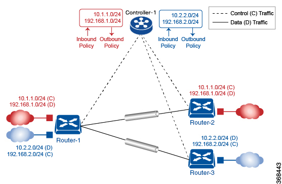
The figure shows the propagation of routing information inside a VRF.

In this figure:
-
Router-1 subscribes to two VRFs, red and blue.
-
The red VRF caters to the prefix 10.1.1.0/24 (either directly through a connected interface or learned using the IGP or BGP).
-
The blue VRF caters to the prefix 10.2.2.0/24 (either directly through a connected interface or learned using the IGP or BGP).
-
-
Router-2 subscribes to the red VRF.
-
This VRF caters to the prefix 192.168.1.0/24 (either directly through a connected interface or learned using the IGP or BGP).
-
-
Router-3 subscribes to the blue VRF.
-
This VRF caters to the prefix 192.168.2.0/24 (either directly through a connected interface or learned using the IGP or BGP).
-
Because each router has an OMP connection over a TLS tunnel to a vSmart controller, it propagates its routing information to the vSmart controller. On the vSmart controller, the network administrator can enforce policies to drop routes, to change TLOCs (which are overlay next hops) for traffic engineering or service chaining). The network administrator can apply these policies as inbound and outbound policies on the vSmart controller.
All prefixes belonging to a single VRF are kept in a separate route table. This provides the Layer 3 isolation required for the various segments in the network. So, Router-1 has two VRF route tables, and Router-2 and Router-3 each have one route table. In addition, the vSmart controller maintains the VRF context of each prefix.
Separate route tables provide isolation on a single node. So now the question is how to propagate the routing information across the network.
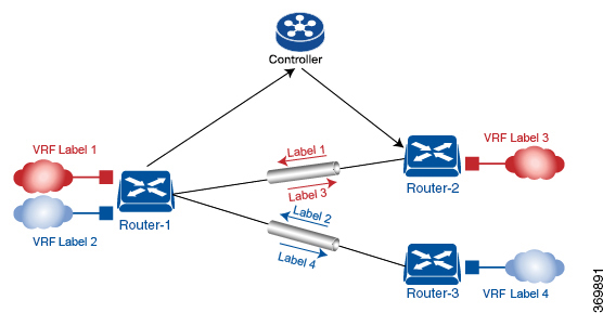
In the Cisco SD-WAN solution, this is done using VRF identifiers, as shown in the figure below. A VRF ID carried in the packet identifies each VRF on a link. When you configure a VRF on a Router, the VRF has a label associated with it. The Router sends the label, along with the VRF ID, to the vSmart controller. The vSmart controller propagates this Router-to- VRF-ID mapping information to the other Routers in the domain. The remote Routers then use this label to send traffic to the appropriate VRF. The local Routers, on receiving the data with the VRF ID label, use the label to demultiplex the data traffic. This is similar to how MPLS labels are used. This design is based on standard RFCs and is compliant with regulatory procedures (such as PCI and HIPAA).

It is important to point out that the transport network that connects the routers is completely unaware of the VRFs. Only the routers know about VRFs; the rest of the network follows standard IP routing.


 Feedback