The documentation set for this product strives to use bias-free language. For the purposes of this documentation set, bias-free is defined as language that does not imply discrimination based on age, disability, gender, racial identity, ethnic identity, sexual orientation, socioeconomic status, and intersectionality. Exceptions may be present in the documentation due to language that is hardcoded in the user interfaces of the product software, language used based on RFP documentation, or language that is used by a referenced third-party product. Learn more about how Cisco is using Inclusive Language.
A Cisco IOS XE SD-WAN device can act as a transparent bridge, switching traffic between LANs that are part of a Virtual Local Area Network (VLAN) at the
site of local router. To implement bridging, each VLAN acts as a separate broadcast domain, and each has its own Ethernet
switching table (or MAC table) to use for switching traffic within the broadcast domain. Multiple VLANs can coexist in a single
Cisco IOS XE SD-WAN device.
To allow hosts associated with different VLANs to communicate with each other, Cisco IOS XE SD-WAN devices support Switch Virtual Interface (SVI). SVIs provide Layer 3 routing services to allow traffic exchange between various
VLANs. Each VLAN can have a single SVI.
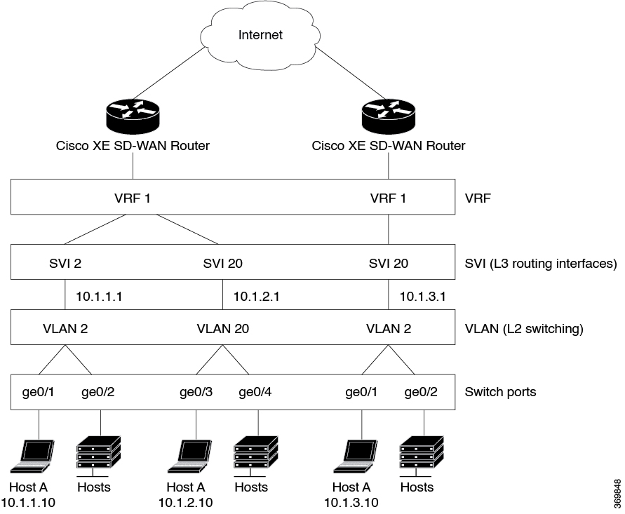
Components of Bridging
The following figure illustrates the components of bridging in Cisco SD-WAN for Cisco IOS XE SD-WAN devices.
Figure 1. Components of Bridging
VLANs
What is a VLAN
A VLAN is a switched network that is logically segmented by function, project team,
or application, without regard to the physical locations of the users. VLANs provide
the means to divide LAN into smaller broadcast domains. VLANs have the same
attributes as physical LANs, but you can group end stations even if they are not
physically located on the same LAN segment. Any device port can belong to a VLAN,
and unicast, broadcast, and multicast packets are forwarded and flooded only to end
stations in the VLAN. Each VLAN is considered a logical network, and packets
destined for stations that do not belong to the VLAN must be forwarded through a
router or a device supporting fallback bridging. In a device stack, VLANs can be
formed with ports across the stack. Because a VLAN is considered a separate logical
network, it contains its own bridge Management Information Base (MIB) information
and can support its own implementation of spanning tree.
VLANs are often associated with IP subnetworks. For example, all the end stations in
a particular IP subnet belong to the same VLAN. Interface VLAN membership on the
device is assigned manually on an interface-by-interface basis. When you assign
device interfaces to VLANs by using this method, it is known as interface-based, or
static, VLAN membership. Traffic between VLANs must be routed. The device can route
traffic between VLANs by using device virtual interfaces (SVIs). An SVI must be
explicitly configured and assigned an IP address to route traffic between VLANs.
Ports that connect to WAN segments are associated with VLANs. In the Cisco SD-WAN
overlay network, these ports are the physical Gigabit Ethernet interfaces on Cisco IOS XE SD-WAN devices.
Specifically, they are the base interfaces, for example, Gi0/1/0.
There is a one-to-one association between an SVI and a VLAN. An SVI can be associated
only with one VLAN, and the other way around.
Native VLANs
Native VLAN is used primarily on trunk ports. VLAN provides backwards compatibility for devices that do not support VLAN tagging.
For example, native VLAN allows trunk ports to accept all traffic regardless of what devices are connected to the port. Without
native VLAN, the trunk ports would accept traffic only from devices that support VLAN tagging.
SVI
VLANS divide a LAN into smaller broadcast domains. Each VLAN is a separate broadcast domain, and switching within that domain
directs traffic to destinations within the VLAN. The result is that hosts within a single bridge domain can communicate among
themselves, but cannot communicate with hosts in other VLANs.
The only way for the traffic to cross Layer 2 VLAN boundaries to allow communication between VLANs is through Layer 3 routing.
Switch Virtual Interfaces (SVI) on Cisco IOS XE SD-WAN devices is designed to provide basic Layer 3 functions for the Layer 2 switch ports that belong to a specific VLAN. SVI is a logical
interface that inherits all the properties of a regular interface, but is not associated with a port or with a physical interface.
The switch ports on Cisco IOS XE SD-WAN devices do not natively support Layer 3 addresses. They must be assigned to an SVI and use a VLAN interface to enable Layer 3 features.
To configure IP routing, you need to assign IP addresses to Layer 3 network interfaces, in this case SVI. This enables communication
with the hosts on those interfaces that use IP. IP routing is disabled by default, and no IP addresses are assigned to Switch
Virtual Interfaces (SVIs).
VRF
Virtual Routing and Forwarding (VRF) associates a VRF instance with an SVI to map VLANs to different logical or physical VPN
WAN connections. VRF allows a single physical router to have multiple route tables to enable multiple routing instances. In
a single network component, multiple VRF resources create the isolation between virtual networks.
VLAN and Switchport Support
Cisco 1000 Series Integrated Services Routers and Cisco 4000 Series Integrated Services Routers with NIM-ES modules support
switchports and VLANs.
Supported Switch Modules
The following switch modules are supported.
NIM-ES2-4: Single-wide NIM form factor
NIM-ES2-8: Single-wide NIM form factor
NIM-ES2-8-P: Single-wide NIM form factor
Restrictions for Cisco IOS XE SD-WAN Devices
Configuring MAC aging time per VLAN is not supported. You can only configure global MAC aging time.
Setting a maximum limit for MAC addresses per VLAN is not supported.
Configuring a single static MAC address on multiple switch ports is not supported.
Packet statistics is not supported on VLANs.
Bridge Domain Interface (BDI) is not supported on the Cisco ASR 1000.
Configure Bridging Using Cisco vManage
Use the Switch Port template to configure bridging for Cisco SD-WAN.
To have a Cisco IOS XE SD-WAN device act as a bridge, configure VLANs on the router. A router can have up to 16 VLANS.
Configure Switchports
In Cisco vManage, choose Configuration > Templates.
In the Device tab, click Create Template.
From the Create Template drop-down, choose From Feature Template.
From the Device Model drop-down, choose the type of device for which you are creating the template.
Click the Additional Templates tab located directly beneath the Description field, or scroll to the Additional Templates section.
Click the plus sign (+) next to Switch Port.
In the Switch Port drop-down, choose the port number.
If the switch port you want to choose does not exist, from the lower Switch Port drop-down, click Create Template. The Switch Port template form is displayed. The top of the form contains fields for naming the template, and the bottom
contains fields for defining switch port parameters.
In the Template Name field, enter a name for the template. The name can be up to 128 characters and can contain only alphanumeric
characters.
In the Template Description field, enter a description of the template. The description can be up to 2048 characters and can
contain only alphanumeric characters.
When you first open a feature template, for each parameter that has a default value, the scope is set to Default (indicated
by a check mark), and the default setting or value is shown. To change the default or to enter a value, click the scope drop-down
to the left of the parameter field and select one of the following:
Table 1.
Parameter Scope
Scope Description
Device Specific (indicated by a host icon)
Use a device-specific value for the parameter. For device-specific parameters, you cannot enter a value in the feature template.
You enter the value when you attach a Viptela device to a device template .
When you click Device Specific, the Enter Key box opens. This box displays a key, which is a unique string that identifies
the parameter in a CSV file that you create. This file is an Excel spreadsheet that contains one column for each key. The
header row contains the key names (one key per column), and each row after that corresponds to a device and defines the values
of the keys for that device. You upload the CSV file when you attach a Cisco SD-WAN device to a device template.
To change the default key, type a new string and move the cursor out of the Enter Key box.
Examples of device-specific parameters are system IP address, hostname, GPS location, and site ID.
Global (indicated by a globe icon)
Enter a value for the parameter, and apply that value to all devices.
Examples of parameters that you might apply globally to a group of devices are DNS server, syslog server, and interface MTUs.
Configure Basic Switch Port Parameters
To configure basic switch port parameters, select the Basic Configuration tab and configure the following parameters:
Table 2.
Parameter Name
Description
Slot
Enter the number of the slot in which the Layer 2 switch port module is installed.
Sub-Slot
Enter the number of the sub-slot.
Module
Select the switch port module type. You can choose from 4, 8, or 22 ports.
To save the feature template, click Save.
Associate Interfaces with the Switch Port
To associate an interface with the switch port, click the Interface tab and click Add New Interface.
The Wlan-GigabitEthernet0/1/8 interface applies only to C1111-8PW and C1111-8PLTExxW routers. When you configure this interface,
select either C1111-8PW or C1111-8PLTExxW when you create a switch port, and select 8 port from the Module drop-down list. In addition, from the New Interface drop-down menu, make sure to choose Wlan-GigabitEthernet0/1/8.
Table 3.
Parameter Name
Description
Interface Name
Enter the name of the interface to associate with the bridging domain, in the format Gislot/sub-slot/port.
Shutdown
Click No to enable the interface. By default, an interface is disabled.
Switch Port
Select the switch port mode:
Access—Configure the interface as an access port. You can configure only one VLAN on an access port, and the port can carry
traffic for only one VLAN.
VLAN Name—Enter a description for the VLAN.
VLAN ID—Enter the VLAN number, which can be a value from 1 through 4094.
Trunk—Configure the interface as a trunk port. You can configure one or more VLANs on a trunk port, and the port can carry
traffic for multiple VLANs.
Allowed VLANs—Enter the numbers of the VLANs for which the trunk can carry traffic.a description for the VLAN.
Native VLAN ID—Enter the number of the VLAN allowed to carry untagged traffic.
Click Save.
To use the switch port for routing, associate it with an SVI.
Configure Other Interface Properties
To configure other interface properties, choose the Advanced tab and configure the following properties:
Note
For Cisco IOS XE SD-WAN devices, you cannot configure MAC age-out time and static MAC address per interface. You can only configure them globally.
Table 4.
Parameter Name
Description
Age-Out Time
Enter how long an entry is in the MAC table before it ages out. Set the value to 0 to prevent entries from timing out.Range: 0, 10 through 1000000 secondsDefault: 300 seconds
Static MAC Address
Click Add Static MAC Address to map a MAC address to a switch port. In the MAC Static Address field that appears, enter the following:
MAC Address—Enter the static MAC address to map to the switch port interface.
Switch Port Interface Name—Enter the name of the switch port interface.
VLAN ID—Enter the number of the VLAN for the switch port.
Click Add to save the static MAC address mapping.
Click Save.
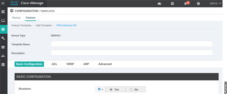
Configure VPN Interface SVI using vManage
Use the VPN Interface SVI template to configure SVI for Cisco IOS XE SD-WAN devices. You configure a switch virtual interface (SVI) to configure a VLAN interface.
To configure DSL interfaces on Cisco routers using Cisco vManage templates, create a VPN Interface SVI feature template to configure VLAN interface parameters.
Create VPN Interface SVI Template
In Cisco vManage, choose Configuration > Templates.
In the Device tab, click Create Template.
From the Create Template drop-down, select From Feature Template.
From the Device Model drop-down, select the type of device for which you are creating the template.
If you are configuring the SVI in the transport VPN (VPN 0):
Click the Transport & Management VPN tab located directly beneath the Description field, or scroll to the Transport & Management VPN section.
Under Additional VPN 0 Templates located to the right of the screen,
click VPN Interface SVI.
If you are configuring the SVI in a service VPN (VPNs other than VPN 0):
Click the Service VPN tab located directly beneath the Description field, or scroll to the Service VPN section.
In the Service VPN drop-down list, enter the
number of the service VPN.
Under Additional VPN Templates located to the
right of the screen, click VPN Interface
SVI.
From the VPN Interface SVI drop-down, click
Create Template. The VPN Interface SVI template
form is displayed.
The top of the form contains fields for naming the template, and the bottom
contains fields for defining VLAN Interface parameters.
In the Template Name field, enter a name for the template. The name can be up to 128 characters and can contain only alphanumeric characters.
In the Template Description field, enter a description of the template. The description can be up to 2048 characters and can contain only alphanumeric
characters.
When you open a feature template initially, for each parameter that has a default
value, the scope is set to Default (indicated by a check mark), and the default
setting or value is shown. To change the default or to enter a value, click the
scope drop-down to the left of the parameter field.
Configure Basic Interface Functionality
Table 5. Feature History
Feature Name
Release Information
Description
Support for Configuring Secondary IP Address
Cisco IOS XE Release 17.2.1r
You can configure up to four secondary IPv4 or IPv6 addresses,
and up to four DHCP helpers. Secondary IP addresses can be
useful for forcing unequal load sharing between different
interfaces, for increasing the number of IP addresses in a LAN
when no more IPs are available from the subnet, and for
resolving issues with discontinuous subnets and classful routing
protocol.
To configure basic VLAN interface functionality in a VPN, select the Basic Configuration tab and configure the following parameters.
Parameters marked with an asterisk are required to configure an interface.
Table 6.
Parameter Name
Description
Shutdown*
Click No to enable the VLAN interface.
VLAN Interface Name*
Enter the VLAN identifier of the interface.Range: 1
through 1094.
Description
Enter a description for the interface.
IP MTU
Specify the maximum MTU size of packets on the
interface.Range: 576 through 1500. Default:
2000 bytes
IPv4* or IPv6
Click to configure one or more IPv4 of IPv6 addresses for the
interface. (Beginning with Cisco IOS XE SD-WAN Release
17.2.)
IPv4 Address*
IPv6 Address
Enter the IPv4 address for the interface.
Secondary IP Address
Click Add to enter up to four secondary IP
addresses. (Beginning with Cisco IOS XE SD-WAN Release
17.2.)
DHCP Helper*
Enter up to eight IP addresses for DHCP servers in the network to
have the interface be a DHCP helper. Separate each address with
a comma. A DHCP helper interface forwards BOOTP (Broadcast) DHCP
requests that it receives from the specified DHCP servers.
Click Add to configure up to four DHCP
helpers. (Beginning with Cisco IOS XE SD-WAN Release 17.2, for
IPv6.)
To save the feature template, click Save.
Apply Access Lists
To apply a rewrite rule, access lists, and policers to a router interface, select the ACL tab and configure the following parameters:
Table 7.
Parameter Name
Description
Ingress ACL – IPv4
Click On and specify the name of the
access list to apply to IPv4 packets being received on the
interface.
Egress ACL – IPv4
Click On and specify the name of the
access list to apply to IPv4 packets being transmitted on the
interface.
Ingress Policer
Click On and specify the name of the
policer to apply to packets being received on the interface.
Egress Policer
Click On and specify the name of the
policer to apply to packets being transmitted on the
interface.
To save the feature template, click Save.
Configure VRRP
To have an interface run the Virtual Router Redundancy Protocol (VRRP), which allows multiple routers to share a common virtual
IP address for default gateway redundancy, select the VRRP tab. Then click Add New VRRP and configure the following parameters:
Table 8.
Parameter Name
Description
Group ID
Enter the virtual router ID, which is a numeric identifier of the virtual router. You can configure a maximum of 24 groups.Range: 1 through 255
Priority
Enter the priority level of the router. There router with the highest priority is elected as the primary router. If two Cisco IOS XE SD-WAN devices have the same priority, the one with the higher IP address is elected as the primary one. Range: 1 through 254Default: 100
Timer
Specify how often the primary VRRP router sends VRRP advertisement messages. If the subordinate routers miss three consecutive
VRRP advertisements, they elect a new primary router.Range: 1 through 3600 secondsDefault: 1 second
Track OMP
Track Prefix List
By default, VRRP uses of the state of the service (LAN) interface on which it is running to determine which Cisco IOS XE SD-WAN device is the primary virtual router. if a Cisco IOS XE SD-WAN device loses all its WAN control connections, the LAN interface still indicates that it is up even though the router is functionally
unable to participate in VRRP. To take WAN side connectivity into account for VRRP, configure one of the following:
Track OMP—Click On for VRRP to track the Overlay Management Protocol (OMP) session running on the WAN connection. If the primary VRRP router
loses all its OMP sessions, VRRP elects a new default gateway from those that have at least one active OMP session.
Track Prefix List—Track both the OMP session and a list of remote prefixes, which is defined in a prefix list configured on
the local router. If the primary VRRP router loses all its OMP sessions, VRRP failover occurs as described for the Track OMP
option. In addition, if reachability to one of the prefixes in the list is lost, VRRP failover occurs immediately, without
waiting for the OMP hold timer to expire, thus minimizing the amount of overlay traffic is dropped while the Cisco IOS XE SD-WAN device determines the primary VRRP router.
IP Address
Enter the IP address of the virtual router. This address must be
different from the configured interface IP addresses of both the
local Cisco IOS XE SD-WAN device and the peer running VRRP.
Add ARP Table Entries
To configure static Address Resolution Protocol (ARP) table entries on the interface, select the ARP tab. Then click Add New ARP and configure the following parameters:
Table 9.
Parameter Name
Description
IP Address
Enter the IP address for the ARP entry in dotted decimal notation or as a fully qualified host name.
MAC Address
Enter the MAC address in colon-separated hexadecimal notation.
To save the ARP configuration, click Add.
To save the feature template, click Save.
Configure Other Interface Properties
To configure other interface properties, select the Advanced tab and configure the following properties:
Table 10.
Parameter Name
Description
TCP MSS
Specify the maximum segment size (MSS) of TPC SYN packets passing
through the Cisco IOS XE SD-WAN device. By default, the MSS is dynamically adjusted based on the
interface or tunnel MTU such that TCP SYN packets are never
fragmented.Range: 552 to 1460 bytesDefault:
None
ARP Timeout
Specify how long it takes for a dynamically learned ARP entry to time out.Range: 0 through 2678400 seconds (744 hours)Default: 1200 (20 minutes)
To save the feature template, click Save.
Configure Bridging Using CLI for Cisco IOS XE SD-WAN Devices
To configure bridging on Cisco IOS XE SD-WAN devices, you must create VLANs to enable L2 switching, and SVIs to enable routing traffic between various VLANs. Follow these steps
to configure Bridging on Cisco IOS XE SD-WAN devices.
Configure VLANs
VLANs enable L2 switching by creating separate broadcast domains.
Create a VLAN.
vlan10nameatmcommit
Configure a trunk interface. A trunk interface allows a switch port to carry traffic from multiple VLANs.
Note: Cisco IOS XE SD-WAN devices do not support modifying MAC aging-time for individual VLANs. Only global configuration on MAC aging-time is supported.
[Optional] Configure static MAC address.
mac address-table static0001.1111.1111vlan 100 interface Gigabitethernet0/1/0commit
Configuration Example
The following example shows how to attach an access mode switchport to a VLAN name.
config-transaction
  vlan 10
   name test
   commit
   exit
   !
 interface GigabitEthernet0/1/2
  switchport mode access
  switchport access vlan name test
  commit
Configure SVI
After you create VLANs to enable L2 switching between hosts, you must configure Switch Virtual Interfaces (SVI) to be able
to route traffic between various VLANs.
Create an SVI interface to associate it with the VLAN you created in the Create VLAN topic.
Run the show ip interface brief command to verify the creation of SVI.
Device# show ip interface brief
Interface              IP-Address      OK? Method Status                Protocol

GigabitEthernet0/1/1   unassigned      YES NVRAM  up                    up

GigabitEthernet0/2/0   unassigned      YES unset  up                    up

GigabitEthernet0/2/1   unassigned      YES unset  up                    up

GigabitEthernet0       10.10.10.1      YES other  up                    up

Vlan1                  unassigned      YES unset  up                    up

Vlan10                 192.0.2.1       YES other  up                    up


 Feedback