Configuring the Cellular Pluggable Interface Module (PIM)

This chapter contains the following sections:

Before You Begin


Important


This configuration guide supports multiple products and is written as generically as possible. Throughout this document, the controller will be referred to as the generic term slot . The slot will take the form of x/x/x in this guide. When configuring the controller on your particular router/pluggable, use the information available in your product documentation, or the tables below.

For information on supported antennas and accessories, see the Cisco Industrial Routers and Industrial Wireless Access Points Antenna Guide.


Note


You must configure an Access Point Name (APN) for the cellular Profiles 1 and 15, when using either profiles 2-14 for cellular connectivity.

Multiple PDN Contexts

This feature enables the router to connect to multiple (currently two) packet data networks. This allows users to enable different features independently on each PDN. For instance, the first PDN can be used for public Internet access and the second one for VPN connectivity; each PDN has its own set of IP addresses and QoS characteristics. It assumes the dual PDN is supported on SIM subscription and services plan from your single mobile carrier.

During the initialization of the router, two cellular interfaces corresponding to the two PDNs are created:

  • cellular 0/x/0

  • cellular 0/x/1

These interfaces can be viewed as two logical interfaces using the same radio resources. For the rest of this guide, the interface cellular 0/x/0 is referred as the first PDN, and cellular 0/x/1 as the second PDN.

The first step, in bringing up the two PDNs, is applying the configuration on both the cellular interfaces and their corresponding lines, in order to make two simultaneous data calls.

The next step is associating the data-bearer profile with its corresponding cellular interface or PDN. It is sufficient to associate the profile for just the first PDN under the controller cellular configuration. Note that the second PDN assumes a profile that is just one above the profile used for the first PDN. For example, if the first PDN uses profile 1, the second PDN uses profile 2 automatically when the call is initiated for the second one.

After the interesting traffic is routed through these cellular interfaces, data calls are initiated, and each interface is assigned its own IP and DNS addresses provided by the cellular network. Note that both PDNs share radio resources. Therefore, any throughput measurement needs to take into account the aggregate throughput on both PDNs, instead of just one.

Router Cellular Architecture

The SIM numbering is always 0/1 if the pluggable supports dual SIM, or 0 if the pluggable is a single SIM (P-LTE-VZ).

The configuration commands used are controller cellular and interface cellular.

  • Controller cellular — Configures all of the parameters related to LTE.

  • Interface cellular — Configures all of the parameters related to the interface (not PDN) such as IPv4, IPv6, and dialer-xxx.


    Note


    The controller and the interface have the same numbering convention.

The following table helps to illustrate these relationships.

Router

Controller/Interface

Slot

ESR6300

0/3/0

0/3 (location up to the integrator)

IR1101 series

0/1/x

Base Unit

0/3/x

Expansion module top (EM) side

0/4/x

Expansion module bottom (CM) side

IR1800 series

0/4/x

0/4 (left side)

0/5/x

0/5 (right side)

IR8100 series

0/2/x

Dependent on the slot configuration. See the Cisco Catalyst IR8140 Heavy Duty Router Installation Guide.

0/3/x

Dependent on the slot configuration. See the Cisco Catalyst IR8140 Heavy Duty Router Installation Guide.

IR8300 series

0/4/x

Left side

0/5/x

Right side

ISR1000 series

0/2/x

Back side right

Catalyst 8200 series

0/2/x

Back side center

Catayst 8300 series

0/2/x

Dependent on module and configuration. See the Hardware Installation Guide for Cisco Catalyst 8300 Series Edge Platforms.

0/3/x

Dependent on module and configuration. See the Hardware Installation Guide for Cisco Catalyst 8300 Series Edge Platforms.

Catalyst 8200 UCPE

0/2/x

Back side center

Verifying Modem Signal Strength and Service Availability

Procedure

  Command or Action Purpose

Step 1

show cellular slot network

Example:

Router# show cellular x/x/x network

Displays information about the carrier network, cell site, and available service.

Step 2

show cellular slot radio details

Example:

Router# show cellular x/x/x radio details

Shows the radio signal strength.

Note

 
The RSSI should be better than –90 dBm for steady and reliable connection.

Step 3

show cellular slot profile

Example:

Router# show cellular x/x/x profile

Shows information about the modem data profiles created.

Step 4

show cellular slot security

Example:

Router# show cellular x/x/x security

Shows the security information for the modem, such as SIM and modem lock status.

Step 5

show cellular slot all

Example:

Router# show cellular x/x/x all

Shows consolidated information about the modem, profiles created, radio signal strength, network security, and so on.

Example

The following is the output of show cellular 0/1/0 all on an IR1101 with a P-LTEAP18-GL.
IR1101#show cellular 0/1/0 all
Hardware Information
====================
Modem Firmware Version = 32.00.116
Host Firmware Version = 32.00.007
Device Model ID = LM960A18
International Mobile Subscriber Identity (IMSI) = 310170205101138
International Mobile Equipment Identity (IMEI) = 356299100001310
Integrated Circuit Card ID (ICCID) = 89011702272051011382
Mobile Subscriber Integrated Services
Digital Network-Number (MSISDN) =
Modem Status = Modem Online
Current Modem Temperature = 39 deg C
PRI version = 1026, Carrier = Generic
OEM PRI version = 32101006

Profile Information
====================

Profile 1 = ACTIVE* **
--------
PDP Type = IPv4
PDP address = 10.52.50.241
IPv4 PDP Connection is successful
Access Point Name (APN) = m2m.com.attz
Authentication = None
Primary DNS address = 8.8.8.8
Secondary DNS address = 8.8.4.4

Profile 2 = INACTIVE
--------
PDP Type = IPv4
Access Point Name (APN) = m2m.com.attz
Authentication = None

Profile 3 = INACTIVE
--------
PDP Type = IPv4
Access Point Name (APN) = mmsbouygtel.com
Authentication = None

Profile 5 = INACTIVE
--------
PDP Type = IPv4
Access Point Name (APN) = orange
Authentication = None

Profile 16 = INACTIVE
--------
PDP Type = IPv4
Access Point Name (APN) = test
Authentication = None

* - Default profile
** - LTE attach profile


Configured default profile for active SIM 0 is profile 1.


Data Connection Information
===========================
Profile 1, Packet Session Status = ACTIVE
Cellular0/1/0:
Data Packets Transmitted = 26 , Received = 24
Data Transmitted = 1900 bytes, Received = 2311 bytes
IP address = 10.52.50.241
Primary DNS address = 8.8.8.8
Secondary DNS address = 8.8.4.4
Profile 2, Packet Session Status = INACTIVE
Profile 3, Packet Session Status = INACTIVE
Profile 4, Packet Session Status = INACTIVE
Profile 5, Packet Session Status = INACTIVE
Profile 6, Packet Session Status = INACTIVE
Profile 7, Packet Session Status = INACTIVE
Profile 8, Packet Session Status = INACTIVE
Profile 9, Packet Session Status = INACTIVE
Profile 10, Packet Session Status = INACTIVE
Profile 11, Packet Session Status = INACTIVE
Profile 12, Packet Session Status = INACTIVE
Profile 13, Packet Session Status = INACTIVE
Profile 14, Packet Session Status = INACTIVE
Profile 15, Packet Session Status = INACTIVE
Profile 16, Packet Session Status = INACTIVE


Network Information
===================
Current System Time = Wed Apr 27 8:48:13 2022
Current Service Status = Normal
Current Service = Packet switched
Current Roaming Status = Roaming
Network Selection Mode = Automatic
Network = F-Bouygues Telecom
Mobile Country Code (MCC) = 208
Mobile Network Code (MNC) = 20
Packet switch domain(PS) state = Attached
LTE Carrier Aggregation state = Deconfigured
Registration state(EMM) = Registered
EMM Sub State = Normal Service
Tracking Area Code (TAC) = 30440
Cell ID = 128697859
Negotiated network MTU = 1430

Radio Information
=================
Radio power mode = Online
LTE Rx Channel Number(PCC) = 3175
LTE Tx Channel Number(PCC) = 21175
LTE Band = 7
LTE Bandwidth = 15 MHz
Current RSSI = -60 dBm
Current RSRP = -91 dBm
Current RSRQ = -14 dB
Current SNR = 14.8 dB
Physical Cell Id = 378
Number of nearby cells = 1
Idx PCI (Physical Cell Id)
--------------------------------
1 378
Radio Access Technology(RAT) Preference = AUTO
Radio Access Technology(RAT) Selected = LTE
Network Change Event = unknown


LTE bands supported by modem:
- Bands 1 2 3 4 5 7 8 12 13 14 17 18 19 20 25 26 28 29 30 32 38 39 40 41 42 43 46 48 66 71.
LTE band Preference settings for the active sim(slot 0):
- Bands 1 2 3 4 5 7 8 12 13 14 17 18 19 20 25 26 28 29 30 32 38 39 40 41 42 43 46 48 66 71.

3G bands supported by modem:
Index:
23 - UMTS Band 1: 2100 MHz (IMT)
24 - UMTS Band 2: 1900 MHz (PCS A-F)
26 - UMTS Band 4: 1700 MHz (AWS A-F)
27 - UMTS Band 5: US 850 MHz (CLR)
50 - UMTS Band 8: 900 MHz (E-GSM)
51 - UMTS Band 9: Japan 1700 MHz
61 - UMTS Band 19: 800 MHz (800 Japan)
3G band Preference settings for the active sim(slot 0):
Index:
23 - UMTS Band 1: 2100 MHz (IMT)
24 - UMTS Band 2: 1900 MHz (PCS A-F)
26 - UMTS Band 4: 1700 MHz (AWS A-F)
27 - UMTS Band 5: US 850 MHz (CLR)
50 - UMTS Band 8: 900 MHz (E-GSM)
51 - UMTS Band 9: Japan 1700 MHz
61 - UMTS Band 19: 800 MHz (800 Japan)

===========================================

Band index reference list:

For LTE and 5G, indices 1-128 correspond to bands 1-128.

For 3G, indices 1-64 maps to the 3G bands mentioned against each above.


Modem Security Information
==========================
Active SIM = 0
SIM switchover attempts = 0
Card Holder Verification (CHV1) = Disabled
SIM Status = OK
SIM User Operation Required = None
Number of CHV1 Retries remaining = 3

Cellular Firmware List
==========================
Idx Carrier FwVersion PriVersion Status
1 Generic 32.00.116 1026 Active
2 Verizon 32.00.126 2022 Inactive
3 ATT 32.00.147 4024 Inactive
4 TMUS 32.00.156 5005 Inactive

Firmware Activation mode = MANUAL

FOTA Information
=================
FOTA Server is not configured

SMS Information
===============
Incoming Message Information
----------------------------
SMS stored in modem = 0
SMS archived since booting up = 0
Total SMS deleted since booting up = 0
Storage records allocated = 25
Storage records used = 0
Number of callbacks triggered by SMS = 0
Number of successful archive since booting up = 0
Number of failed archive since booting up = 0


Outgoing Message Information
----------------------------
Total SMS sent successfully = 0
Total SMS send failure = 0
Number of outgoing SMS pending = 0
Number of successful archive since booting up = 0
Number of failed archive since booting up = 0
Last Outgoing SMS Status = SUCCESS
Copy-to-SIM Status = 0x0
Send-to-Network Status = 0x0
Report-Outgoing-Message-Number:
Reference Number = 0
Result Code = 0x0
Diag Code = 0x0 0x0 0x0 0x0 0x0

SMS Archive URL =

Mobile app service = Not Available

Modem Crashdump Information
===========================
Modem crashdump logging = off

Dying Gasp Information
===========================
Dying Gasp Detach = Disabled
SMS = Disabled


Packet drop stats
=================

Source IP violation stats:
Total dropped IPv4 packets: 0
Recently violated IPv4 addresses (Max 4):

Total dropped IPv6 packets: 0
Recently violated IPv6 addresses (Max 4):

IR1101#

Using Data Profiles

Customized profiles, Access Point Name (APN) in mobile networks, can be created and used on the cellular pluggable module. Maximum number of profiles that can be created are 16.

Each profile is created for a given firmware, for example, AT&T. If you switch to a different firmware, for example, Generic PTCRB, you must create a profile. When two active PDN are supported by the SIM card subscription, each interface for example, cellular 0/x/0 and 0/x/1, should have its dedicated profile created.

When the profile is created, using global or config mode, it is stored in the PIM itself. This means you can create a profile, write erase your configuration to allow PnP process to work, since it requires no configuration on the router.

In cases where profile configurations are not available, separate profiles should be created with required parameters.

Guidelines for Creating, Modifying, or Deleting Modem Data Profiles

Follow these guidelines when you configure a data profile using EXEC mode or Config mode:

  • You do not have to make any profile-related changes if your modem comes with a data profile, for instance, AT&T, Sprint, and Verizon.

  • If any profile parameter changes are required for a connection type, the changes will likely be carried out in the default profiles.


    Note


    In a private network with Verizon, it is recommended to create a profile 3 with parameter changes such APN and profile 1 for ATT.
  • To configure different profile types and use them for a different connection, you can create separate profiles with different parameters (for instance, APN names). Note that only one profile is active at a given time.

  • Use the show cellular <slot> profile command to view the data profile. An asterisk(*) symbol is displayed against the data profile. Double asterisk(**) symbol is displayed against the attach profile.

  • The data profile is used to set up a data call. If you want to use a different profile, that profile needs to be made the default one. Use the lte sim data-profile <number> command to change the default profile under controller cellular x/x/x.

Creating, Modifying, or Deleting Data Profiles Using EXEC Mode

Customized profiles Access Point Name (APN) in mobile networks can be created and used on the cellular pluggable interface module. Maximum number of profiles that can be created are 16.

Cisco SKU's shipping with specific carrier provisioning file default profiles are already populated and can be deployed readily. These can be found in carrier label under the show cellular slot hardware command.

Procedure

Command or Action Purpose

cellular slot lte profile [create | delete] profile-number [apn [authentication [username password [bearer-type ]]]]

Example:

Router# cellular x/x/x lte profile create 2 apn.com pap username pwd ipv4

Creates, modifies, or deletes a modem data profile in the privileged EXEC mode.

  • The profile-number argument specifies the profile number created for the modem.

  • (Optional) The apn argument specifies an Access Point Name (APN). An APN is provided by your service provider. Only a single APN can be specified for a single profile.

  • (Optional) The authentication parameter specifies the authentication type used. Acceptable parameters are chap, none (no authentication), pap, and pap_chap (PAP or CHAP authentication).

  • (Optional) The username and password arguments are given by a service provider. These are mandatory when an authentication type other than none is used.

  • (Optional) The PDN type parameter specifies the type of packet data session established with mobile network using this profile. Acceptable parameters are ipv4, ipv6, and ipv4v6 (IPv4 and IPv6).

The show cellular slot profile command displays configured profile list.

Note


Single asterisk(*) displayed against data profile.

Double asterisk(**) displayed against attached profile.

Example

router# show cellular x/x/x profile 
Profile 1 = INACTIVE **
--------
PDP Type = IPv4v6
Access Point Name (APN) = vzwims
Authentication = None
 
Profile 2 = INACTIVE
--------
PDP Type = IPv4v6
Access Point Name (APN) = vzwadmin
Authentication = None
 
Profile 3 = ACTIVE*
--------
PDP Type = IPv4v6
PDP address = 100.119.136.44
PDP IPV6 address = 2600:1010:B00E:1E11:192D:3E20:199B:3A70/64  Scope: Global
Access Point Name (APN) = VZWINTERNET
Authentication = None
        Primary DNS address = 198.224.173.135
        Secondary DNS address = 198.224.174.135
        Primary DNS IPV6 address = 2001:4888:68:FF00:608:D:0:0
        Secondary DNS IPV6 address = 2001:4888:61:FF00:604:D:0:0
 
Profile 4 = INACTIVE
--------
PDP Type = IPv4v6
Access Point Name (APN) = vzwapp
Authentication = None
 
Profile 5 = INACTIVE
--------
PDP Type = IPv4v6
Access Point Name (APN) = vzw800
Authentication = None
 
Profile 6 = INACTIVE
--------
PDP Type = IPv4v6
Access Point Name (APN) = CISCO.GW4.VZWENTP
Authentication = None
 
  * - Default profile
 ** - LTE attach profile
#show cellular x/x/x profile
Profile 1 = INACTIVE **
--------
PDP Type = IPv4v6
Access Point Name (APN) = vzwims
Authentication = None

Profile 2 = INACTIVE
--------
PDP Type = IPv4v6
Access Point Name (APN) = vzwadmin
Authentication = None

Profile 3 = ACTIVE*
--------
PDP Type = IPv4v6
PDP address = 100.86.69.19
PDP IPV6 address = 2600:1010:B040:DA58:1C27:D97:321E:18C4/64  Scope: Global
Access Point Name (APN) = VZWINTERNET
Authentication = None
	Primary DNS address = 198.224.173.135
	Secondary DNS address = 198.224.174.135
	Primary DNS IPV6 address = 2001:4888:68:FF00:608:D:0:0
	Secondary DNS IPV6 address = 2001:4888:61:FF00:604:D:0:0

Profile 4 = INACTIVE
--------
PDP Type = IPv4v6
Access Point Name (APN) = vzwapp
Authentication = None

Profile 5 = INACTIVE
--------
PDP Type = IPv4v6
Access Point Name (APN) = vzw800
Authentication = None

Profile 6 = INACTIVE
--------
PDP Type = IPv4v6
Access Point Name (APN) = vzwclass6
Authentication = None

  * - Default profile 
 ** - LTE attach profile


Configured default profile for active SIM 0 is profile 3.

Note


If data and attach profile bindings need modification, use the controller cellular slot command.
router(config-controller)# lte sim data-profile 3 attach-profile 2 slot slot
 
Router#show cellular x/x/x profile
Profile 1 = INACTIVE
--------------------------------------------------
PDP Type = IPv4v6
Access Point Name (APN) = test
Authentication = None
 
Profile 2 = INACTIVE **
--------
PDP Type = IPv4
Access Point Name (APN) = internet
Authentication = PAP or CHAP
Username =  user@solution.com
Password =  cisco
 
Profile 3 = INACTIVE*
--------
PDP Type = IPv4v6
Access Point Name (APN) = basic
Authentication = None
 
  * - Default profile
 ** - LTE attach profile
Configured default profile for active SIM 0 is profile 2.

Creating, Modifying, or Deleting Data Profiles Using Configuration Mode

Procedure

Command or Action Purpose

profile id id-number apn apn-name authentication username-password pdn-type pdn-type no-overwrite

Example:

Router(config-controller) profile id 1 apn 
apn_internet authentication none pdn-type ipv4 no-overwrite

Configures a cellular profile in the configuration mode.

  • The id argument specifies the profile number created for the modem. The maximum number of profiles that can be created for each modem is 16.

  • (Optional) The apn argument specifies an Access Point Name (APN) in the profile. An APN is provided by your service provider. Only a single APN can be specified in a single profile.

  • (Optional) The authentication parameter specifies the authentication type used. Acceptable parameters are chap , none (no authentication), pap , and pap_chap (PAP or CHAP authentication).

  • (Optional) The username and password arguments are provided by a service provider. These are mandatory when an authentication type is used other than none.

  • (Optional) The PDN-type parameter specifies the type of packet data session established with mobile network using this profile. Acceptable parameters are: ipv4, ipv6 and ipv4v6 (IPv4 and IPv6).

  • (Optional) No-overwrite action to be taken when a profile already exists in modem for the profile id. If there is a profile already exists in the modem for this profile id and no-overwrite option is specified, this configuration will not overwrite existing profile. Default is overwrite.

Example: Changing a Default Profile

The following example shows how to change a default profile:


router(config-controller)# lte sim data-profile 2 attach-profile 1 slot slot

The following example shows the output of the show cellular command for Verizon network service:


router# show cellular x/x/x profile 
Profile 1 = INACTIVE **
--------
PDP Type = IPv4v6
Access Point Name (APN) = vzwims
Authentication = None

Profile 2 = INACTIVE
--------
PDP Type = IPv4v6
Access Point Name (APN) = vzwadmin
Authentication = None

Profile 3 = ACTIVE*
--------
PDP Type = IPv4v6
PDP address = 100.119.136.44
PDP IPV6 address = 2600:1010:B00E:1E11:192D:3E20:199B:3A70/64  Scope: Global
Access Point Name (APN) = VZWINTERNET
Authentication = None
        Primary DNS address = 198.224.173.135
        Secondary DNS address = 198.224.174.135
        Primary DNS IPV6 address = 2001:4888:68:FF00:608:D:0:0
        Secondary DNS IPV6 address = 2001:4888:61:FF00:604:D:0:0

Profile 4 = INACTIVE
--------
PDP Type = IPv4v6
Access Point Name (APN) = vzwapp
Authentication = None

Profile 5 = INACTIVE
--------
PDP Type = IPv4v6
Access Point Name (APN) = vzw800
Authentication = None

Profile 6 = INACTIVE
--------
PDP Type = IPv4v6
Access Point Name (APN) = CISCO.GW4.VZWENTP
Authentication = None

  * - Default profile
 ** - LTE attach profile 

Example: Cellular Profile Configuration

The following is an example configuration under cellular profile:


router(config-controller)# profile id 1 apn apn_internet authentication none pdn-type ipv4 no-overwrite

Controller Cellular Running Configuration

Router #show running-config controller cellular <slot>
Building configuration...

Current configuration : 330 bytes
!
controller Cellular x/x/x
profile id 1 apn apn_internet authentication none pdn-type ipv4 no-overwrite
end


 ** This will override exec mode profile configuration
 ** If for a profile ID, configuration CLI exists, exec mode configuration cannot be performed. 

Router #show cellular <slot> profile 5
Profile 5 = INACTIVE
--------
PDP Type = IPv4
Access Point Name (APN) = apn_old
Authentication = None

TSN1#cellular <slot> lte profile create 5 apn_new
Warning: You are attempting to create Profile 5
	Profile 5 was configured through controller configuration 'profile id <profile #>'
	Please execute command under controller configuration using '[no] profile id <profile #>' for profile 5 to create
	Profile 5 NOT written to modem


** As part of this enhancement, any attach and/or data profile changes will immediately 
trigger a connection reset and take effect. Below warning message will be displayed. 

Warning: You are attempting to modify the data/attach profile.
Connection will be reset

Applying a Modem Profile in a SIM Configuration

Procedure

  Command or Action Purpose

Step 1

configure terminal

Example:

Router# configure terminal

Enters the global configuration mode.

Step 2

controller cellular <slot>

Example:

Router(config)# controller cellular x/x/x

Enters the cellular controller configuration mode.

Step 3

lte sim data-profile data-profile-number attach-profile number slot

Applies the configured profile number to the SIM and its slot number. The default (primary) slot is 0.

The attach profile is the profile used by the modem to attach to the cellular network.

The data profile is the profile used to send and receive data over the cellular network.

The slot number helps specify different data and attach profiles for two different carrier SIMs.

Resetting the Modem to Factory Default

IOS XE release 17.12.1 introduced a new command to factory reset the modem to remove any profiles and APNs configured.


Note


The LTE cellular-profile-cleanup feature works for one modem, and not for dual modems, and when GENERIC firmware is active.

Use the following procedure:

  1. Configure the following under controller:

    controller Cellular 0/x/0
    no lte firmware auto-sim
    lte cellular-profile-cleanup
    
  2. The following message appears:

    **************************************************
    Modem cellular profiles will be deleted during next reload
    if this cli is enabled and factory reset button is pressed.
    **********************************************************
    
  3. Save the configuration.

  4. Check that the modem has generic firmware using the show cell 0/x/0 firmware command.


    Note


    If modem has the generic firmware activated, no need to go to step 5, and proceed to step 7.
  5. Activate the Generic Firmware.

    1. P-5GS6-GL modem:

      cellular 0/x/0 lte mno-activate <mno index>
    2. Other LTE modems:

      cellular 0/x/0 lte firmware-activate <firmware index>
  6. Verify that the modem has generic firmware using the show cell 0/x/0 firmware command.

  7. Power cycle the router.

  8. Remove the SIM from modem.

  9. Proceed with the reset procedure (press the reset button and then plug in the power cable).

  10. After the router boots up, the following message will appear:

    % CELLULAR_PROFILE_CLEANUP_ON_RESET rommon variable set to FALSE successfully.
  11. All user created profiles will be removed, and only the default profile remains.

Data Call Setup

To set up a data call, use the following procedures:

Configuring the Cellular Interface


Note


A NAT configuration may be needed to get full IP connectivity. See the example below.

To configure the cellular interface, enter the following commands starting in EXEC mode.

If a tunnel interface is configured with ip unnumbered cellular x/x/x, it is necessary to configure the actual static IP address under the cellular interface, in place of ip address negotiated assuming your mobile carrier allows it.


Note


As a best practice, you should not use the cellular interface IP address for the tunnel.

Procedure

  Command or Action Purpose

Step 1

configure terminal

Example:

Router# configure terminal

Enters global configuration mode.

Step 2

interface cellular slot

Example:

Router(config)# interface cellular x/x/x

Specifies the cellular interface.

Step 3

ip address negotiated

Example:

Router(config-if)# ip address negotiated

Specifies that the IP address for a particular interface is dynamically obtained.

Step 4

dialer in-band

Example:

Router(config-if)# dialer in-band

Enables DDR and configures the specified serial interface to use in-band dialing.

Step 5

dialer watch-group <group-number>

Example:

Router(config-if)# dialer watch-group 1

Specifies the number of the dialer access group to which the specific interface belongs.

Step 6

exit

Example:

Router(config-if)# exit

Enters the global configuration mode.

Step 7

ip route <network-number> <network-mask> {<ip-address> | <interface>} [<administrative distance>] [name <name> ]

Example:

Router(config)# ip route 209.165.200.225 255.255.255.224 cellular x/x/x

Establishes a floating static route with the configured administrative distance through the specified interface.

Note

 
A higher administrative distance should be configured for the route through the backup interface so that it is used only when the primary interface is down.

Step 8

dialer-list <dialer-group> protocol <protocol-name> permit | deny | list access-list-number | access-group

Example:


Router(config)# dialer-list 1 protocol ip list 1

Creates a dialer list for traffic of interest and permits access to an entire protocol.

Example


unicast-routing
ipv6
interface Cellular0/2/0
ip address negotiated
ip nat outside  
dialer in-band
dialer idle-timeout 0  
dialer watch-group 1
ipv6 enable
no shutdown

interface GigabitEthernet0/0/0
 ip address 192.168.60.1 255.255.255.0
 ip nat inside
 ipv6 address autoconfig

ip nat inside source list 1 interface Cellular0/1/0 overload
ip route 0.0.0.0 0.0.0.0 Cellular0/1/0
ipv6 route ::/0 Cellular0/1/0
 
ip access-list standard 1
 10 permit 192.168.60.0 0.0.0.255
dialer watch-list 1 ip 5.6.7.8 255.255.255.255
dialer-list 1 protocol ip permit

Configure Cellular Interface with dialer watch-group

A dialer watch-group allows you to define a group of routes based on IP address and mask and assign that group to a group-number. If no routes to these networks are in the routing table, the router dials a backup connection.

To configure the cellular interface with dialer watch-group, enter the following commands starting in EXEC mode.

Procedure

  Command or Action Purpose

Step 1

configure terminal

Example:

Router# configure terminal

Enters global configuration mode.

Step 2

interface cellular slot

Example:

Router(config)# interface cellular x/x/x

Specifies the cellular interface.

Step 3

ip address negotiated

Example:

Router(config-if)# ip address negotiated

Specifies that the IP address for a particular interface is dynamically obtained.

Step 4

dialer in-band

Example:

Router(config-if)# dialer in-band

Enables DDR and configures the specified serial interface to use in-band dialing.

Step 5

ip address negotiated

Example:

Router(config-if)# ip address negotiated

Specifies that the IP address for a particular interface is dynamically obtained.

Step 6

dialer idle-timeout <seconds>

Example:

Router(config-if)# dialer idle-timeout 30

Specifies the duration of idle time, in seconds, after which a line has no outbound traffic. “0” second means no idle timeout. The default idle timeout is 120 seconds if there is no idle timer specified.

Step 7

dialer watch-group <group-number>

Example:

Router(config-if)# dialer watch-group 1

Enables Dialer Watch on the specific interface.

Step 8

exit

Example:

Router(config-if)# exit

Enters the global configuration mode.

Step 9

dialer-list <dialer-group> protocol <protocol-name> {permit | deny | list} <access-list-number> <group-number>

Example:

Router(config)# dialer-list 1 protocol ip list 1

Creates a dialer list for traffic of interest and permits access to an entire protocol.

Step 10

access-list <access-list-number> permit <ip-source-address>

Example:

Router(config)# access-list 1 permit any

Defines traffic of interest.

Step 11

dialer watch-list <watch-group number> <ip> <ip mask>

Example:

Router(config)# dialer watch-list 1 ip 5.6.7.8 255.255.255.255

Defines traffic of interest.

Step 12

dialer watch-list <watch-group number> delay route-check initial <time in seconds>

Example:

Router(config)# dialer watch-list 1 delay route-check initial 60

Defines traffic of interest.

Step 13

dialer watch-list <watch-group number> delay connected <seconds>

Example:

Router(config)# dialer watch-list 1 delay connect 1

Defines traffic of interest.

Carrier Aggregation

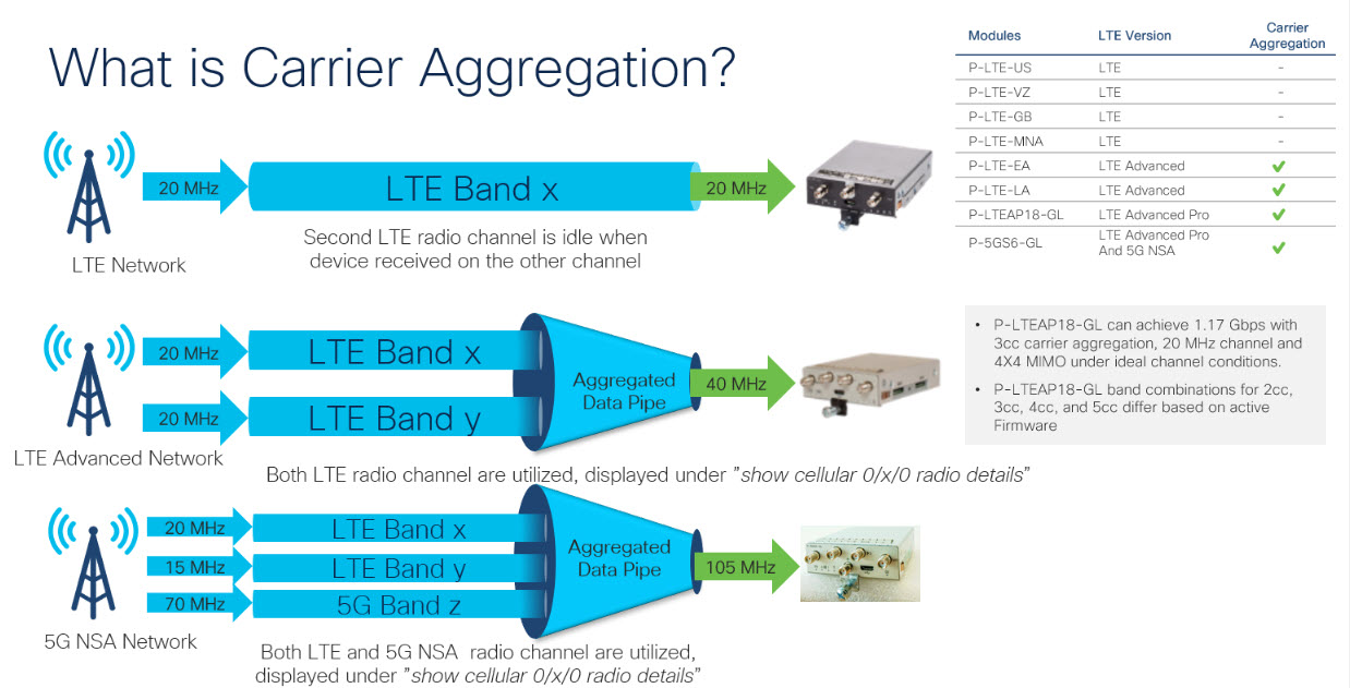
Carrier aggregation makes it possible for carriers to transmit data to a device like a wireless router over multiple network bands at once, through a single “aggregated data pipe.” LTE Advanced with carrier aggregation utilizes multiple frequency bands at once, devices switch frequency bands in just a few milliseconds. Additionally, even if one band drops, the device stays connected via the second band in the aggregated data pipe.

Refer to the following figure for an example:

Figure 1. Carrier Aggregation

Carrier aggregation can be monitored by using the show cellular 0/x/0 radio details command:

IR1821#show cell 0/4/0 radio details
 Modem Radio is Online
 Main Antenna details:
 RSSI = -51 dBm
 RSRP = 75 dBm
 Diversity Antenna details:
 RSSI = -54 dBm
 RSRP = 81 dBm
 SCC information available
 SCC[0]:
 PCI = 27
 State = Deactivated
 Band = 3
 Rx Channel Number = 1850
 Bandwidth = 20 MHz
 SCC[1]:
 PCI = 27
 State = Deactivated
 Band = 1
 Rx Channel Number = 251
 Bandwidth = 10 MHz
 SCC[2]:
 PCI = 27
 State = Deactivated
 Band = 7
 Rx Channel Number = 3175
 Bandwidth = 15 MHz
 SCC[3]: Not Available

PCC CA information:
 LTE band class = Band 20
 E-UTRA absolute radio frequency channel number of the serving cell = 6200
 Bandwidth = 10 MHz
 Physical Cell Id = 27
 Current RSRP in 1/10 dBm as measured by L1 = -75
 Current RSSI in 1/10 dBm as measured by L1 = -49
 Current RSRQ in 1/10 dBm as measured by L1 = -10
 Measured SINR in dB = 136
 Tracking area code information for LTE = 30440

 SCC 0 CA information:
 LTE band class = Band 3
 E-UTRA absolute radio frequency channel number of the serving cell = 1850
 Bandwidth = 20 MHz
 Physical Cell Id = 27
 Current RSRP in 1/10 dBm as measured by L1 = -89
 Current RSSI in 1/10 dBm as measured by L1 = -64
 Current RSRQ in 1/10 dBm as measured by L1 = -5
 Measured SINR in dB = 0
 Current SCC state = Configured

Example: Showing Carrier Aggregation

The following are examples of an IR1101 showing carrier aggregation (CA) for both 4G/LTE and 5G NSA.

First is show cellular 0/1/0 all Notice the radio section only contains details on the Primary Channel that is also used for Control Plane.

Router#show cell 0/1/0 all
Hardware Information
====================
Modem Firmware Version = M0H.030200-B012
Host Firmware Version = A0H.000300-B012
Device Model ID =  FN980
International Mobile Subscriber Identity (IMSI) = 208018903906177
International Mobile Equipment Identity (IMEI) = 359661100035944
Integrated Circuit Card ID (ICCID) = 89330120410034176680
Mobile Subscriber Integrated Services
Digital Network-Number (MSISDN) = 
Modem Status = Modem Online
Current Modem Temperature = 42 deg C
PRI version = 0880-109, Carrier = Generic GCF
OEM PRI version = 0880-109

Profile Information
====================

Profile 1 = ACTIVE* **
--------
PDP Type = IPv4
PDP address = 10.44.198.163
IPv4 PDP Connection is successful
Access Point Name (APN) = orange
Authentication = None
       Primary DNS address = 192.168.10.110

Profile 2 = INACTIVE
--------
PDP Type = IPv4v6
Access Point Name (APN) = ims
Authentication = None

Profile 15 = INACTIVE
--------
PDP Type = IPv4
Access Point Name (APN) = Broadband
Authentication = None

  * - Default profile 
 ** - LTE attach profile


Configured default profile for active SIM 0 is profile 1.

Data Connection Information
===========================
Profile 1, Packet Session Status = ACTIVE
       Cellular0/1/0:
       Data Packets Transmitted = 9249463 ,  Received = 9382548 
       Data Transmitted = 2289007661 bytes, Received = 3415239855 bytes
        IP address = 10.44.198.163
       Primary DNS address = 192.168.10.110
Profile 2, Packet Session Status = INACTIVE
Profile 3, Packet Session Status = INACTIVE
Profile 4, Packet Session Status = INACTIVE
Profile 5, Packet Session Status = INACTIVE
Profile 6, Packet Session Status = INACTIVE
Profile 7, Packet Session Status = INACTIVE
Profile 8, Packet Session Status = INACTIVE
Profile 9, Packet Session Status = INACTIVE
Profile 10, Packet Session Status = INACTIVE
Profile 11, Packet Session Status = INACTIVE
Profile 12, Packet Session Status = INACTIVE
Profile 13, Packet Session Status = INACTIVE
Profile 14, Packet Session Status = INACTIVE
Profile 15, Packet Session Status = INACTIVE
Profile 16, Packet Session Status = INACTIVE

Network Information
===================
Current System Time = Wed Apr 20 12:29:50 2022
Current Service Status = Normal
Current Service = Packet switched
Current Roaming Status = Home
Network Selection Mode = Automatic
Network = Orange F
Mobile Country Code (MCC) = 208
Mobile Network Code (MNC) = 1
Packet switch domain(PS) state = Attached
Registration state(EMM) = Registered
EMM Sub State = Normal Service
Tracking Area Code (TAC) = 50443
Cell ID = 24246021
Negotiated network MTU = 1500

Radio Information
=================
Radio power mode = Online
LTE Rx Channel Number(PCC) =  6400
LTE Tx Channel Number(PCC) =  24400
LTE Band =  20
LTE Bandwidth = 10 MHz
Current RSSI = -57 dBm
Current RSRP = -87 dBm
Current RSRQ = -13 dB
Current SNR = 13.2  dB
Physical Cell Id = 48
Number of nearby cells = 2
Idx      PCI (Physical Cell Id)
--------------------------------
1              48
2              242
Radio Access Technology(RAT) Preference = AUTO 
Radio Access Technology(RAT) Selected = LTE
Network Change Event = activated 5G ENDC


LTE bands supported by modem:
- Bands 1 2 3 4 5 7 8 12 13 14 17 18 19 20 25 26 28 29 30 32 34 38 39 40 41 42 43 46 48 66 71.
LTE band Preference settings for the active sim(slot 0):
- Bands 1 2 3 4 5 7 8 12 13 14 17 18 19 20 25 26 28 29 30 32 34 38 39 40 41 42 43 46 48 66 71.

NR5G bands supported by modem:
- Bands 1 2 3 5 7 8 12 20 25 28 38 40 41 48 66 71 77 78 79.
NR5G band Preference settings for the active sim(slot 0):
- Bands 1 2 3 5 7 8 12 20 25 28 38 40 41 48 66 71 77 78 79.

3G bands supported by modem:
Index:
  23 - UMTS Band 1: 2100 MHz (IMT)
  24 - UMTS Band 2: 1900 MHz (PCS A-F)
  26 - UMTS Band 4: 1700 MHz (AWS A-F)
  27 - UMTS Band 5: US 850 MHz  (CLR)
  50 - UMTS Band 8: 900 MHz  (E-GSM)
  51 - UMTS Band 9: Japan 1700 MHz
  61 - UMTS Band 19: 800 MHz (800 Japan)
3G band Preference settings for the active sim(slot 0):
Index:
  23 - UMTS Band 1: 2100 MHz (IMT)
  24 - UMTS Band 2: 1900 MHz (PCS A-F)
  26 - UMTS Band 4: 1700 MHz (AWS A-F)
  27 - UMTS Band 5: US 850 MHz  (CLR)
  50 - UMTS Band 8: 900 MHz  (E-GSM)
  51 - UMTS Band 9: Japan 1700 MHz
  61 - UMTS Band 19: 800 MHz (800 Japan)

===========================================

Band index reference list:

For LTE and 5G, indices 1-128 correspond to bands 1-128.

For 3G, indices 1-64 maps to the 3G bands mentioned against each above.


Modem Security Information
==========================
Active SIM = 0
SIM switchover attempts = 0
Card Holder Verification (CHV1) = Disabled
SIM Status = OK
SIM User Operation Required = None
Number of CHV1 Retries remaining = 3

Cellular Firmware List
==========================
 Idx Carrier              FwVersion        PriVersion   Status  
 1   Generic GCF          M0H.030200-B012  0880         Active  

Firmware Activation mode  =  MANUAL

Modem image running: Main
Mobile Network Operator: Generic GCF
Number of MNO's = 14
 Index MNO ID  MNO NAME
 1     0       Generic GCF
 2     1       Generic PTCRB
 3     10      AT&T
 4     11      T-Mobile
 5     12      Verizon Wireless
 6     14      Bell
 7     15      Rogers
 8     16      Telus
 9     20      SK Telecom
 10    21      SK Telecom Dongle
 11    30      NTT Docomo
 12    31      KDDI
 13    40      Telstra
 14    50      Anatel

FOTA Information
=================
FOTA Server is not configured

GPS Information
==========================
GPS Feature =  enabled
GPS Mode Configured =  standalone
GPS Port Selected =  Dedicated GPS port
GPS Status =  GPS acquiring
Last Location Fix Error =  Offline [0x0]
Latitude =  0 Deg 0 Min 0 Sec North
Longitude =  0 Deg 0 Min 0 Sec East
Timestamp (GMT) =  Sun Jan  6 00:00:00 1980

Fix type =  2D, Height =  0 m
HDOP =  , GPS Mode Used =  not configured

Satellite Info
----------------

SMS Information
===============
Incoming Message Information
----------------------------
SMS stored in modem = 1
SMS archived since booting up = 0
Total SMS deleted since booting up = 0
Storage records allocated = 25
Storage records used = 1
Number of callbacks triggered by SMS = 0
Number of successful archive since booting up = 0
Number of failed archive since booting up = 0

Outgoing Message Information
----------------------------
Total SMS sent successfully = 0
Total SMS send failure = 0
Number of outgoing SMS pending = 0
Number of successful archive since booting up = 0
Number of failed archive since booting up = 0
Last Outgoing SMS Status = SUCCESS
Copy-to-SIM Status =     0x0
Send-to-Network Status = 0x0
Report-Outgoing-Message-Number:
  Reference Number =     0
  Result Code =          0x0
  Diag Code =            0x0 0x0 0x0 0x0 0x0

SMS Archive URL = 

Mobile app service = Not Available

Modem Crashdump Information
===========================
Modem crashdump logging = off

Dying Gasp Information
===========================
 Dying Gasp Detach =  Disabled
 SMS =  Disabled


Packet drop stats
=================

Source IP violation stats:
 Total dropped IPv4 packets: 0
 Recently violated IPv4 addresses (Max 4):

 Total dropped IPv6 packets: 0
 Recently violated IPv6 addresses (Max 4):
#Router

Next, the show cellular 0/1/0 radio details displays all Secondary Channels (SCC) for both 4G/LTE and 5G NSA (ENDC). Each channel displays its band and channel bandwidth, for example, 5G channel is band n78 and 90MHz bandwidth, as well as Radio signal quality.

Router#show cell 0/1/0 radio details
 Modem Radio is Online
 Main 0 Antenna details:
 RSSI = -57 dBm
 RSRP = 87 dBm
 Diversity 0 Antenna details:
 RSSI = -59 dBm
 RSRP = 89 dBm

 SCC information available
 SCC[0]:
 PCI = 48
 State = Deactivated
 Band = 3
 Rx Channel Number = 1300
 Bandwidth = 20 MHz
 SCC[1]:
 PCI = 48
 State = Deactivated
 Band = 7
 Rx Channel Number = 3000
 Bandwidth = 20 MHz
 SCC[2]:
 PCI = 48
 State = Deactivated
 Band = 1
 Rx Channel Number = 524
 Bandwidth = 15 MHz
 SCC[3]: Not Available

 5G CC information:
 ENDC active band = 78
 ENDC Bandwidth (MHz) = 90
 ENDC active downlink channel = 650400
 ENDC active uplink channel = 650400
 ENDC Physical Cell Id = 99
 Current ENDC RSRP in 1/10 dBm as measured by L1 = -111
 Current ENDC RSSI in 1/10 dBm as measured by L1 = -100
 Current ENDC RSRQ in 1/10 dBm as measured by L1 = -11
 Measured ENDC SINR in dB = 95

PCC CA information:
 LTE band class = Band 20
 E-UTRA absolute radio frequency channel number of the serving cell = 6400
 Bandwidth = 10 MHz
 Physical Cell Id = 48
 Current RSRP in 1/10 dBm as measured by L1 = -87
 Current RSSI in 1/10 dBm as measured by L1 = -58
 Current RSRQ in 1/10 dBm as measured by L1 = -12
 Measured SINR in dB = 163
 Tracking area code information for LTE = 50443

 SCC 0 CA information:
 LTE band class = Band 3
 E-UTRA absolute radio frequency channel number of the serving cell = 1300
 Bandwidth = 20 MHz
 Physical Cell Id = 48
 Current RSRP in 1/10 dBm as measured by L1 = -98
 Current RSSI in 1/10 dBm as measured by L1 = -74
 Current RSRQ in 1/10 dBm as measured by L1 = -4
 Measured SINR in dB = 0
 Current SCC state = Configured

 SCC 1 CA information:
 LTE band class = Band 7
 E-UTRA absolute radio frequency channel number of the serving cell = 3000
 Bandwidth = 20 MHz
 Physical Cell Id = 48
 Current RSRP in 1/10 dBm as measured by L1 = -115
 Current RSSI in 1/10 dBm as measured by L1 = -95
 Current RSRQ in 1/10 dBm as measured by L1 = -3
 Measured SINR in dB = 0
 Current SCC state = Configured

 SCC 2 CA information:
 LTE band class = Band 1
 E-UTRA absolute radio frequency channel number of the serving cell = 524
 Bandwidth = 15 MHz
 Physical Cell Id = 48
 Current RSRP in 1/10 dBm as measured by L1 = -101
 Current RSSI in 1/10 dBm as measured by L1 = -76
 Current RSRQ in 1/10 dBm as measured by L1 = -6
 Measured SINR in dB = 0
 Current SCC state = Configured
Router#

Configuring Cellular Modem Link Recovery

The cellular modem link recovery feature is disabled by default, and it is recommended to enable the link recovery feature.


Note


No manual operations or automated scripts interacting with 4G modems may be possible until and unless the modems have come fully in-service. Modems may take a few minutes after platform bootup and CLI available to be able to allow full interaction and establish IP connectivity. A typical modem power-cycle may also take approximately 4 minutes before any interaction is possible. Modems are in-service after the console displays the following message:

%CELLWAN-2-MODEM_RADIO: Cellularx/x/x Modem radio has been turned on


To enable or disable the cellular modem link recovery feature, if required, perform the following steps:

Procedure

  Command or Action Purpose

Step 1

configure terminal

Example:

Router# configure terminal

Enters global configuration mode.

Step 2

controller cellular <slot>

Example:

Router(config)# controller cellular x/x/x

Enters cellular controller configuration mode.

Step 3

{lte | no lte} modem link-recovery disable

Example:

Router(config-controller)#lte modem link-recovery disable

Router(config-controller)# no lte modem link-recovery disable

Router#show run | sec controller Cellular x/x/x
lte modem link-recovery rssi onset-threshold -110
lte modem link-recovery monitor-timer 20
lte modem link-recovery wait-timer 10
lte modem link-recovery debounce-count 6


Example:
Router#configure terminal
Router(config)#controller Cellular x/x/x
Router(config-controller)#lte modem link-recovery
 monitor-timer 30
Router(config-controller)#lte modem wait-timer 15
Router(config-controller)#lte modem debounce-count 8
Router(config-controller)#lte modem rssi onset-threshold -100

Enables or disables the cellular modem link recovery feature.

Enables or disables the cellular modem link recovery feature.

Once we enable link-recovery, the default Cisco recommended values for link-recovery parameters are populated.

We can change the values of link-recovery parameters from the default Cisco recommended values, by using cli for each parameter like in example.

Note

 
Changing the default recommended cisco values is not advised as it will impact ideal performance of link-recovery feature.

Step 4

end

Example:

Router(config)# end

Exits the configuration mode and returns to the privileged EXEC mode.

Cellular Modem Link Recovery Parameters

There are four configurable parameters to adjust the behavior of cellular link recovery. The default values optimized for the best performance of the feature and changing it is not recommended unless advised by Cisco.

The following table explains the link recovery parameters.:

Table 1. Link Recovery Parameters

Parameter

Description

rssi onset-threshold

This parameter defines the RSSI value below which the link recovery feature triggers additional scrutiny to look for potential issues and act if needed. The range of this parameter can be set from -90 dBm to -125 dBm. The recommended and default value is -110 dBm.

monitor-timer

This parameter determines how often link recovery looks for potential issues. The default value for this parameter is 20 seconds meaning that link recovery feature will be triggered every 20 seconds and look at certain parameters to determine if there is a potential issue. You can configure the monitor-timer range between 20 to 60 seconds. Increasing the monitor timer value above 20 seconds will increase the response time of the feature.

wait-timer and debounce-count

The wait-timer parameter is used in conjunction with the debounce-count parameter to perform more frequent, additional checks, once the link recovery feature has identified a potential issue that needs to be recovered from, with a modem power-cycle. The default value for wait-timer is 10 seconds and the default value for debounce- count is 6. With this setting, once link recovery has identified an inoperative modem state, it performs additional checks every 10 seconds, up to 6 times, to determine if the issue has been resolved without a modem power-cycle. Reducing the debounce-count and the wait-timer makes faster link recovery, while reducing them may increase the time for recovery. The configurable range for wait-timer is 5-60 seconds. The configurable range for debounce-count is 6-20 seconds.

Verifying the Cellular Modem Link Recovery Configuration

To determine if the cellular modem link recovery is enabled, use the show controller cellular slot command.

Router# show controller cellular 0/4/0

Interface Cellular0/4/0
5G Advanced Pro CAT-18 pluggable-Global Multimode LTE/LTE-A/LTE-AP/DC-HSPA+/HSP unit 4

Cellular Modem Configuration
==============================
Modem is recognized as valid
Power save mode is OFF
manufacture id = 0x00001BC7 product id = 0x00001050
Telit Wireless Direct IP FN980 modem
Modem Uplink Speed = 542000 kbit.
Modem Downlink Speed = 3800000 kbit.

GPS Feature = enabled
GPS Status = NMEA Disabled
GPS Mode = standalone
GPS Port selected = Dedicated GPS port

Cellular Dual SIM details:
---------------------------
SIM 0 is not present
SIM 1 is present
SIM 1 is active SIM

Module OIR Details
-----------------------------------------------
Module type : P-5GS6-GL
Module Serial Number : FOC25031VY2
Module Last Inserted on : Tue Apr 19 17:44:45 2022
-----------------------------------------------

Module Reload Statistics
-------------------------
Soft OIR reloads = 0
Hard OIR reloads = 0
-------------------------

Modem Management Statistics
---------------------------
Modem resets = 4
Modem timeouts = 0
Link recovery is ON

Registration check is ON
RSSI threshold value is -110 dBm
Monitor Timer value is 20 seconds
Wait Timer value is 10 seconds
Debounce Count value is 6

Link recovery count is 0
User initiated Modem Commands
----------------------------------
Modem user initiated power-cycles = 0
Successful Modem Power Cycles = 0
Failed Modem Power Cycles = 0
Modem user initiated resets = 0
Successful Modem Resets = 0
Failed Modem Resets = 0
Last known modem state = 'application' mode
AT Command Port = /dev/cwan_ttyUSB5
NMEA Port = /dev/cwan_ttyUSB4
DM Port = /dev/cwan_ttyUSB3

DIP MDM link status retry count = 0 pdp context = 0
DIP MDM link up pending = 0 pdp context = 0
DIP MDM link status retry count = 0 pdp context = 1
DIP MDM link up pending = 0 pdp context = 1
DIP MDM link status retry count = 0 pdp context = 2
DIP MDM link up pending = 0 pdp context = 2
IDB with pending DIP call = Cellular0/4/0
IDB Cellular0/4/0: DIP profile id = 1
IDB Cellular0/4/1: DIP profile id = 255
PDN 0 Channel rate (bps) tx = 542000000, rx = 3800000000
Max rate (bps) tx = 542000000, rx = 3800000000
PDN 1 Channel rate (bps) tx = 542000000, rx = 3800000000
Max rate (bps) tx = 542000000, rx = 3800000000
GPS NMEA port = Disabled (Stream OFF)
NMEA queue depth = 0
NMEA packet count = 0
NMEA Stream no: 1 Not Configured
NMEA Stream no: 2 Not Configured
NMEA Stream no: 3 Not Configured
NMEA Stream no: 4 Not Configured
NMEA Stream no: 5 Not Configured
NMEA Stream no: 6 Not Configured
DM port = Disabled


Modem Callback Statistics
---------------------------
PacketServiceCallback_count 1
DataBearerCallback_count 0
DormancyStatusCallback_count 0
PowerCallback_count 0
ByteTotalsCallback_count 0
iByteTotalsCallback_count 0
PacketsCountCallback_count 0
iPacketsCountCallback_count 0
ActivationStatusCallback_count 0
MobileIPStatusCallback_count 0
RoamingIndicatorCallback_count 0
DataCapabilitiesCallback_count 0
SignalStrengthCallback_count 0
iSignalStrengthCallback_count 0
RFInfoCallback_count 0
LURejectCallback_count 0
NewSMSCallback_count 8
SLQSSMSEventCallback_count 0
NMEACallback_count 0
PDSStateCallback_count 0
CATEventCallback_count 0
iCATEventCallback_count 0
DeviceStateChangeCbk_count 7
FwDldCompletionCbk_count 0
SLQSOMADMAlertCallback_count 0
OMADMStateCallback_count 0
SLQSServingSystemCallback_count 0
SLQSBandPreferenceCbk_count 0
USSDReleaseCallback_count 0
USSDNotificationCallback_count 0
SLQSSignalStrengthsCallback_count 0
iSLQSSignalStrengthsCallback_count 0
SLQSSDKTerminatedCallback_count 0
SLQSTransLayerInfoCallback_count 0
SLQSTransNWRegInfoCallback_count 0
SLQSSysSelectionPrefCallBack_count 0
NotifySessionStateDisconnect_count 0
WdsEventCallback_count 87
HeartbeatModemStatisticsCallback_count 0

idb at 0xFFFF6EA094A8, driver data structure at 0xFFFF6EA0B0A0


Cellular Linux F/W Info
-----------------------

Firmware Version = A0H.000300-B016

Modem SDK and Driver Information
---------------------------------

The Current Modem SDK Version is SDK Lite Telit sdk 1.0.29.0
Modem USB-Serial Driver Version is GobiSerial
Modem USB-Net Driver Version is GobiNet

When the cellular modem link recovery occurs and modem is power cycled, you can see the %CELLWAN-2-MODEM_DOWN message on the console logs and additionally there is a %CELLWAN-2-LINK_RECOVERY message which indicates that action has been taken by the cellular modem link recovery feature.

Whenever the cellular modem link recovery has occurred, it updates the Modem timeouts counter under the Modem Management Statistics section of the show controller cellular slot command output. Modem parameters at the last timeout section has information that helps to identify the cause of the issue that triggered link recovery

In the following example log, the messages, modem time out counter, and modem parameters at the last time out are highlighted.

*Jul 19 17:15:18.980 PDT: %CELLWAN-2-LINK_RECOVERY: Cellular x/x/x: Cellular Modem has been power cycled

Configuring Cellular IPv6 Address

This section contains the following:

Cellular IPv6 Addresses

IPv6 addresses are represented as a series of 16-bit hexadecimal fields separated by colons (:) in the format: x:x:x:x:x:x:x:x. Following are two examples of the same IPv6 address:

  • 2001:CDBA:0000:0000:0000:0000:3257:9652

  • 2001:CDBA::3257:9652 (zeros can be omitted)

IPv6 addresses commonly contain successive hexadecimal fields of zeros. Two colons (::) may be used to compress successive hexadecimal fields of zeros at the beginning, middle, or end of an IPv6 address (the colons represent successive hexadecimal fields of zeros). The table below lists compressed IPv6 address formats.

An IPv6 address prefix, in the format ipv6-prefix/prefix-length, can be used to represent bit-wise contiguous blocks of the entire address space. The ipv6-prefix must be in the form documented in RFC 2373 where the address is specified in hexadecimal using 16-bit values between colons. The prefix length is a decimal value that indicates how many of the high-order contiguous bits of the address comprise the prefix (the network portion of the address). For example, 2001:cdba::3257:9652 /64 is a valid IPv6 prefix.

IPv6 Unicast Routing

An IPv6 unicast address is an identifier for a single interface, on a single node. A packet that is sent to a unicast address is delivered to the interface identified by that address.

The Router supports the following address types:

Link-Local Address

A link-local address is an IPv6 unicast address that can be automatically configured on any interface using the link-local prefix FE80::/10 (1111 1110 10) and the interface identifier in the modified EUI-64 format. A link-local address is automatically configured on the cellular interface when an IPv6 address is enabled.

After the data call is established, the link-local address on the cellular interface is updated with the host generated link-local address that consists of the link-local prefix FF80::/10 (1111 1110 10) and the auto-generated interface identifier from the USB hardware address. The figure below shows the structure of a link-local address.

Global Address

A global IPv6 unicast address is defined by a global routing prefix, a subnet ID, and an interface ID. The routing prefix is obtained from the PGW. The Interface Identifier is automatically generated from the USB hardware address using the interface identifier in the modified EUI-64 format. The USB hardware address changes after the router reloads.

Configuring Cellular IPv6 Address

To configure the cellular IPv6 address, perform these steps:

Procedure
  Command or Action Purpose

Step 1

configure terminal

Example:
Router# configure terminal 

Enters global configuration mode.

Step 2

ipv6 unicast-routing

Example:
Router# ipv6 unicast-routing

Enable IPv6 routing globally on the router.

Step 3

interface cellular <slot/port/interface>

Example:
Router(config)# interface cellular 0/1/0 

Specifies the cellular interface.

Step 4

description <text>

Example:
Router(config-if)# description text

Provides a description for the cellular interface, if desired.

Step 5

ipv6 address <options>

Example:
Router(config-if)# ipv6 address negotiated

Specifies that the IP address for a particular interface is dynamically obtained.

Step 6

load-interval <seconds>

Example:
Router(config-if)# load-interval 30

Specifies the length of time for which data is used to compute load statistics.

Step 7

dialer in-band

Example:
Router(config-if)# dialer in-band

Enables DDR and configures the specified serial interface to use in-band dialing.

Step 8

dialer idle-timeout <seconds>

Example:
Router(config-if)# dialer idle-timeout 0

Specifies the dialer idle timeout period.

Step 9

dialer watch-group <group number>

Example:
Router(config-if)# dialer watch-group 1

Specifies the number of the dialer access group to which the specific interface belongs.

Step 10

ipv6 enable

Example:
Router(config-if)# ipv6 enable

Enables IPv6.

Step 11

pulse time <seconds>

Example:
Router(config-if)# pulse-time 1

Define pulse time

Step 12

ip virtual-reassembly

Example:
Router(config-if)# ip virtual-reassembly

Enable Virtual Fragment Reassembly (default is ‘in’ only).

Step 13

no shutdown

Example:
Router(config-if)#no shutdown

No shutdown the interface

Step 14

exit

Example:
Router(config-if)#exit

Exit from the interface configuration.

Step 15

access-list 1 permit any

Example:
Router(config)#access-list 1 permit any

Defines traffic of interest.

Step 16

dialer watch-list 1 <ipaddress> < mask>

Example:
Router(config)#dialer watch-list 1 ip 5.6.7.8 255.255.255.255

Defines IP and mask for a watch list.

Step 17

dialer watch-list 1 delay route-check initial 60

Example:
Router(config)#dialer watch-list 1 delay route-check initial 60

Defines delay for a route check.

Step 18

dialer watch-list 1 delay connect 1

Example:
Router(config)#dialer watch-list 1 delay connect 1

Defines delay for connect.

Step 19

dialer-list 1 protocol ip permit

Example:
Router(config)#dialer-list 1 protocol ip permit

Defines a dial-on-demand routing (DDR) dialer list for dialing by protocol or by a combination of a protocol and a previously defined access list.

Step 20

dialer-list 1 protocol ipv6 permit

Example:
Router(config)#dialer-list 1 protocol ipv6 permit

Permits IPv6 on the dialer list.

Step 21

ipv6 route <destination ipv6 prefix> / <destination mask> {forwarding router address | interface | other options}

Example:
Router(config)#ipv6 route ::/0 Cellular0/1/0

Defines the route.

Step 22

end

Example:
Router(config)#end

Exits to global configuration mode.

The following example shows the Cellular IPv6 configuration .


lte sim data-profile 1 attach-profile 1 slot 0
 lte sim data-profile 1 attach-profile 1 slot 1
 lte interface 0 64 1111:2222:3333:0001
 lte gps mode standalone
 lte modem dm-log size 2
 lte modem dm-log filesize 1
 lte modem dm-log rotation
 lte modem link-recovery disable
!
!
interface Loopback0
 ip address 1.1.1.1 255.255.255.255
!
!
interface Cellular0/1/0
 description Cell-to-CMW
 ip address negotiated
 load-interval 30
 dialer in-band
 dialer idle-timeout 0
 dialer watch-group 1
 ipv6 enable
 pulse-time 1
 ip virtual-reassembly
!
interface Cellular0/1/1
 no ip address
 shutdown
!
…
ip route 0.0.0.0 0.0.0.0 Cellular0/1/0
ipv6 route ::/0 Cellular0/1/0
… 
!
access-list 1 permit any
dialer watch-list 1 ip 5.6.7.8 255.255.255.255
dialer watch-list 1 delay route-check initial 60
dialer watch-list 1 delay connect 1
dialer-list 1 protocol ip permit
dialer-list 1 protocol ipv6 permit
!


Configuring a Deterministic IPv6 Host Address

Deterministic IPv6 addresses allow a user to configure a static, user-specified IPv6 address host portion for the interface. While IPv6 address network and subnet parts may be assigned by the ISP, the host part remains unchanged using this configuration. This allows devices to have known, pre-determined IPv6 addresses in their network.

To configure a deterministic IPv6 host address, perform these steps:

Procedure

  Command or Action Purpose

Step 1

config terminal

Example:

Router# configure terminal

Enters global configuration mode.

Step 2

ipv6 unicast-routing

Example:

Router(config)# ipv6 unicast-routing

Enable IPv6 routing.

Step 3

interface cellular <slot>

Example:

Router(config)# interface Cellular 0/1/0 

Specifies the cellular interface.

Step 4

enable ipv6

Example:

Router(config-if)# enable ipv6

Enables IPv6.

Step 5

ipv6 address autoconfig

Example:

Router(config-if)# ipv6 address autoconfig

Enables automatic configuration of IPv6 addresses using stateless autoconfiguration on an interface and enables IPv6 processing on the interface.

Step 6

no shut

Example:

Router(config-if)#no shut

Shutdown Interface.

Step 7

controller cellular <slot>

Example:

Router(config)# controller cellular 0/1/0

Configure the controller.

Step 8

lte interface <interface number> <address length 48-80> <deterministic address suffix>

Example:

Router(config)# lte interface 0 64  1111:2222:3333:1234

Specify in controller config the deterministic IPv6 address for cellular interface.

Step 9

end

Example:

Router# end

Step 10

clear int cellular 0/1/0

Example:

Router# clear int cellular 0/1/0

Clears the cellular interface and forces the cellular interface to reacquire IP address.

Example

The following example shows the configuration:

controller Cellular 0/1/0
 lte sim data-profile 1 attach-profile 1 slot 0
 lte sim data-profile 1 attach-profile 1 slot 1
 no lte firmware auto-sim
 lte interface 0 64 1111:2222:3333:0001
 lte gps mode standalone
 lte modem dm-log size 2
 lte modem dm-log filesize 1
 lte modem dm-log rotation
 lte modem link-recovery disable
!
!
…
!
interface Loopback0
 ip address 1.1.1.1 255.255.255.255
!
!
interface Cellular0/1/0
 description Cell-to-CMW
 ip address negotiated
 load-interval 30
 dialer in-band
 dialer idle-timeout 0
 dialer watch-group 1
 dialer-group 1
 ipv6 enable
 pulse-time 1
 ip virtual-reassembly
!
interface Cellular0/1/1
 no ip address
 shutdown
!
…
ip route 0.0.0.0 0.0.0.0 Cellular0/1/0
ipv6 route ::/0 Cellular0/1/0
… 
!
access-list 1 permit any
dialer watch-list 1 ip 5.6.7.8 255.255.255.255
dialer watch-list 1 delay route-check initial 60
dialer watch-list 1 delay connect 1
dialer-list 1 protocol ip permit
dialer-list 1 protocol ipv6 permit
!
…

PLMN Search and Selection

This feature allows you to search for available Public Land Mobile Network (PLMN) and connect to one of the PLMN.

PLMN Commands

Use the following commands for PLMN feature:

  • cellular < unit > lte plmn search

  • cellular < unit > lte plmn select < mode > < mcc > < mnc > < rat > < duration >

  • show cellular < unit > network

Searching the Network

You can use the cellular 0 lte plmn search command to search for available PLMNs. This example shows how to search for networks:


router#cellular 0 lte plmn search
Searching for available PLMNs.This may take up to 3 minutes.
Please wait...........................
PLMN search done. Please use "show cellular 0 network" to see available PLMNS

After the search, use the show cellular 0 network command to see the available networks:


router#show cellular 0 network
Current System Time = Fri Sep 18 18:49:24 2015
Current Service Status = Normal
Current Service = Packet switched
Current Roaming Status = Roaming
Network Selection Mode = Manual
Network = O2 - UK
Mobile Country Code (MCC) = 234
Mobile Network Code (MNC) = 10
Packet switch domain(PS) state = Attached
Location Area Code (LAC) = 4931
Cell ID = 34319
Available PLMNs:
Idx MCC MNC RAT     Desc
1   234 10  umts    O2 - UK
2   234 10  gsm     O2 - UK
3   234 20  umts    3 UK
4   234 30  umts    EE
5   234 15  gsm     voda UK
6   234 33  gsm     EE
7   234 20  lte     3 UK
8   234 30  gsm     EE
9   234 15  umts    voda UK
10  234 30  lte     EE
11  234 10  lte     O2 - UK
12  234 15  lte     voda UK

Selecting the Network

There are three ways you can select an available network: Auto mode, Force Mode, and Manual mode. In Auto mode, your router will connect automatically to a network preferred by the SIM. In Force mode, the router is forced to select an available or known network without performing a network search. If a network is not available or the router is unable to attach to a network, then the router will remain in a ‘Not attached’ state. You can use the cellular x lte plmn select auto command to attach the router to a network preferred by the SIM. In Manual mode, you can select an available network from your search result.

This example shows how to select a network manually:


router#cellular 0 lte plmn select manual ?
  <0-999>  Mobile Country Code (MCC)
router#cellular 0 lte plmn select manual 234 ?
  <0-999>  Mobile Network Code (MNC)
router#cellular 0 lte plmn select manual 234 10 ?
  gsm   GSM
  lte   LTE
  umts  UMTS
router#cellular 0 lte plmn select manual 234 10 gsm ?
  permanent    PERMANENT
  power-cycle  POWER_CYCLE
router#cellular 0 lte plmn select manual 234 10 gsm power-cycle ?

  <cr>
router#cellular 0 lte plmn select manual 234 10 gsm power-cycle

This example shows how to force a network selection:


router#cellular 0 lte plmn select force ?
  <0-999>  Mobile Country Code (MCC)
router#cellular 0 lte plmn select force 310 ?
  <0-999>  Mobile Network Code (MNC)
router#cellular 0 lte plmn select force 310 410 ?
  <2-3>  MNC Digits Ex 23 means 2 Digits, 023 Means 3 Digits 
router#cellular 0 lte plmn select force 310 410 2 ?
  gsm   GSM
  lte   LTE
  umts  UMTS

router#cellular 0 lte plmn select force 310 410 2 lte ?
  permanent    PERMANENT
  power-cycle  POWER_CYCLE
Router#cellular 0 lte plmn select force 310 410 2 lte power-cycle ?
  <cr>
Router#cellular 0 lte plmn select force 310 410 2 lte power-cycle

Verifying PLMN Selection

Use show cellular x network command to verify the PLMN selection:


router#show cellular 0 network
Current System Time = Fri Sep 18 18:53:25 2015
Current Service Status = Normal
Current Service = Packet switched
Current Roaming Status = Roaming
Network Selection Mode = Manual
Network = O2 - UK
Mobile Country Code (MCC) = 234
Mobile Network Code (MNC) = 10
Packet switch domain(PS) state = Attached
Location Area Code (LAC) = 4931
Cell ID = 34319
Available PLMNs:
Idx MCC MNC RAT     Desc
1   234 10  umts    O2 - UK
2   234 10  gsm     O2 - UK
3   234 20  umts    3 UK
4   234 30  umts    EE
5   234 15  gsm     voda UK
6   234 33  gsm     EE
7   234 20  lte     3 UK
8   234 30  gsm     EE
9   234 15  umts    voda UK
10  234 30  lte     EE
11  234 10  lte     O2 - UK
12  234 15  lte     voda UK
router#show cellular 0 radio
Radio power mode = ON
Channel Number = 122
Current Band = GSM 900 Extended
Current RSSI = -48 dBm
Current ECIO = -127 dBm
Radio Access Technology(RAT) Preference = GSM
Radio Access Technology(RAT) Selected = EDGE

Note


Some networks may not allow the router to connect. In such cases, you have to choose a different network.

Note


Restart your modem if the router is not able to connect to any network.

Example: PLMN Search

This example shows the output of a PLMN search without SIM card on a P-LTEAP18-GL.

Without a SIM card:

IR1101#show cell 0/1/0 ha
Modem Firmware Version = 32.00.116
Host Firmware Version = 32.00.007
Device Model ID =  LM960A18
International Mobile Subscriber Identity (IMSI) = 
International Mobile Equipment Identity (IMEI) = 356299100001310
Integrated Circuit Card ID (ICCID) = 
Mobile Subscriber Integrated Services
Digital Network-Number (MSISDN) = 
Modem Status = Modem Online
Current Modem Temperature = 37 deg C
PRI version = 1026, Carrier = Generic
OEM PRI version = 32101006
IR1101#

IR1101#show cell 0/1/0 secu
Active SIM = NONE
IR1101#

Performing a PLMN search:

IR1101#cell 0/1/0 lte plmn search 
Searching for available PLMNs...Please wait...
This may take up to 5 minutes..............
PLMN search done. Please use "show cellular x/x/x network" to see available PLMNS

Showing the PLMN display:

IR1101#show cell 0/1/0 net 
Current System Time = Sun Jan 6 0:14:39 1980
Current Service Status = No service
Current Service = Unknown
Current Roaming Status = Roaming
Network Selection Mode = Automatic
Network = 
Mobile Country Code (MCC) = 208
Mobile Network Code (MNC) = 10
Packet switch domain(PS) state = Not attached
LTE Carrier Aggregation state = Deconfigured
Registration state(EMM) = Searching/Not Registered
EMM Sub State = Limited Service
Tracking Area Code (TAC) = 0
Cell ID = 0
Available PLMNs at  =  08:21:25 UTC Thu May 5 2022 
Idx MCC MNC RAT     Desc
1   208 10  lte     SFR
2   208 16  lte     Free
3   208 1   lte     Orange
4   208 20  lte     BYTEL
5   208 15  lte     Free

Network MTU = Not Available
IR1101#

Modem Settings for North America and Carriers Operating on 700 MHz Band

For deployments in North America, and carriers operating in the 700 MHz band, the following changes to the modem settings are required to prevent long network attach times.

To change the modem settings to force the modem to scan different technologies, use the following Cisco IOS command:

Router# cellular 0/0/0 lte technology ? 
auto         Automatic LTE Technology Selection
cdma-1xrtt   CDMA 1xRTT
cdma-evdo    CDMA EVDO Rev A
cdma-hybrid  HYBRID CDMA
gsm          GSM
lte          LTE
umts         UMTS

To select "LTE only", then use the configuration term command under controller cellular x/x/x.

Router(config-controller)#lte modem band-select all-lte-only

Cellular Band Lock

With private cellular networks, customers have a single frequency band to run their private network, for example band 48 (CBRS) in U.S. In this case, the customer can lock the cellular band to the one allocated to the private network.


Note


Bands reporting and locking is dependent from the PIM module.

The cellular PIMs support different 3G, 4G or 5G frequency bands, which can be displayed by the show cellular x/x/x radio band CLI.

Router#show cell x/x/x radio band

LTE bands supported by modem:
- Bands 1 2 3 4 5 7 8 12 13 14 17 18 19 20 25 26 28 29 30 32 38 39 40 41 42 43 46 48 66 71.
LTE band Preference settings for the active sim(slot 0):
- Bands 1 2 3 4 5 7 8 12 13 14 17 18 19 20 25 26 28 29 30 32 38 39 40 41 42 43 46 48 66 71.

3G bands supported by modem:
Index:
  23 - UMTS Band 1: 2100 MHz (IMT)
  24 - UMTS Band 2: 1900 MHz (PCS A-F)
  26 - UMTS Band 4: 1700 MHz (AWS A-F)
  27 - UMTS Band 5: US 850 MHz  (CLR)
  50 - UMTS Band 8: 900 MHz  (E-GSM)
  51 - UMTS Band 9: Japan 1700 MHz
  61 - UMTS Band 19: 800 MHz (800 Japan)
3G band Preference settings for the active sim(slot 0):
Index:
  23 - UMTS Band 1: 2100 MHz (IMT)
  24 - UMTS Band 2: 1900 MHz (PCS A-F)
  26 - UMTS Band 4: 1700 MHz (AWS A-F)
  27 - UMTS Band 5: US 850 MHz  (CLR)
  50 - UMTS Band 8: 900 MHz  (E-GSM)
  51 - UMTS Band 9: Japan 1700 MHz
  61 - UMTS Band 19: 800 MHz (800 Japan)

For reference, the bands listed above map as follows:

  • For 4G and 5G, indices 1-128 correspond to bands 1-128.

  • For 3G, indices 1-64 maps to the 3G bands mentioned against each above.

Dependent of the country and service providers, one or more bands may be used to attach the device to the service provider radio network. This is done automatically since all bands are valid. Therefore, Cisco does not recommend changing the configuration

With private cellular networks, customers have a single frequency band to run their private network, for example band 48 (CBRS) in U.S. In this case, the customer can lock the cellular band to the one allocated to the private network.

This is accomplished with the following command syntax:

Router(config-controller)#lte modem band-select indices umts3g none ?
  lte4g  Specify the LTE indices

Router(config-controller)#lte modem band-select indices umts3g none lte4g 48 ?
  nr5g  Specify the 5g indices
  slot  primary SIM slot

Router(config-controller)#lte modem band-select indices umts3g none lte4g 48 slot 0   

Router(config-controller)#lte modem band-select indices umts3g ?          
  WORD  Band index(es) in string format "<band index#>, <band index#>, ...".   
        (supported 3G band indices are listed under 'show cellular radio
        band'.)
        Enter "none" for no bands or "all" for all supported 3G bands.

Router(config-controller)#lte modem band-select indices umts3g none lte4g ?            
  WORD  Band index(es) in string format "<band index#>, <band index#>, ...".   
        (supported LTE band indices are listed under 'show cellular radio
        band'.)
        Enter "none" for no bands or "all" for all supported LTE bands.

The result should be as follows:

Router#show cell x/x/x radio band

LTE bands supported by modem:
- Bands 1 2 3 4 5 7 8 12 13 14 17 18 19 20 25 26 28 29 30 32 38 39 40 41 42 43 46 48 66 71.
LTE band Preference settings for the active sim(slot 0):
- Bands 48.

Cellular Band 30


Caution


Some of the cellular PIMs support LTE FDD Band 30 transmitter. When a cellular PIM supports LTE FDD band 30 in a U.S. based deployment, activated with an AT&T subscription, then some customers (location dependent) may be at risk of FCC violation in a transportation or roadway scenario. In this case, disabling band 30 is recommended.

Use the following procedure in order to disable Band 30.

Display all bands as set-up by default.

Router#show cell x/x/x radio band

LTE bands supported by modem:
- Bands 1 2 3 4 5 7 8 12 13 14 17 18 19 20 25 26 28 29 30 32 34 38 39 40 41 42 43 46 48 66 71.
LTE band Preference settings for the active sim(slot 0):
- Bands 1 2 3 4 5 7 8 12 13 14 17 18 19 20 25 26 28 29 30 32 34 38 39 40 41 42 43 46 48 66 71.

NR5G bands supported by modem:
- Bands 1 2 3 5 7 8 12 20 25 28 38 40 41 48 66 71 77 78 79.
NR5G band Preference settings for the active sim(slot 0):
- Bands 1 2 3 5 7 8 12 20 25 28 38 40 41 48 66 71 77 78 79.

3G bands supported by modem:
Index:
  23 - UMTS Band 1: 2100 MHz (IMT)
  24 - UMTS Band 2: 1900 MHz (PCS A-F)
  26 - UMTS Band 4: 1700 MHz (AWS A-F)
  27 - UMTS Band 5: US 850 MHz  (CLR)
  50 - UMTS Band 8: 900 MHz  (E-GSM)
  51 - UMTS Band 9: Japan 1700 MHz
  61 - UMTS Band 19: 800 MHz (800 Japan)
3G band Preference settings for the active sim(slot 0):
Index:    
  23 - UMTS Band 1: 2100 MHz (IMT)
  24 - UMTS Band 2: 1900 MHz (PCS A-F)
  26 - UMTS Band 4: 1700 MHz (AWS A-F)
  27 - UMTS Band 5: US 850 MHz  (CLR)
  50 - UMTS Band 8: 900 MHz  (E-GSM)
  51 - UMTS Band 9: Japan 1700 MHz
  61 - UMTS Band 19: 800 MHz (800 Japan)

===========================================

Band index reference list:

For LTE and 5G, indices 1-128 correspond to bands 1-128.

For 3G, indices 1-64 maps to the 3G bands mentioned against each above.

Router#

In order to disable band 30, you have to setup all of the supported bands, omitting the band you do not want. There is no disable function. In this example, band 30 is omitted.

Router#conf term
Enter configuration commands, one per line.  End with CNTL/Z.
Router(config)#controller cellular x/x/x
Router(config-controller)#
Router(config-controller)#lte modem band-select indices ?
  umts3g  
Specify the 3g indices
Router(config-controller)#lte modem band-select indices umts3g all lte4g 1,2,3,4,5,7,8,12,13,14,17,18,19,20,25,26,28,29,32,34,38,39,40,41,42,43,46,48,66,71 nr5g all slot 0 
Router(config-controller)#exit                          
Router(config)#exit
Router#

Verify that the omitted band is not showing on the "preference setting for the active slot". See the following example.

Router#show cell x/x/x radio band

LTE bands supported by modem:
- Bands 1 2 3 4 5 7 8 12 13 14 17 18 19 20 25 26 28 29 30 32 34 38 39 40 41 42 43 46 48 66 71.
Notice band 30 shows in the "bands supported by modem".

LTE band Preference settings for the active sim(slot 0):
- Bands 1 2 3 4 5 7 8 12 13 14 17 18 19 20 25 26 28 29 32 34 38 39 40 41 42 43 46 48 66 71.
Notice band 30 is not available in the "band Preference settings for the active sim(slot 0)"

NR5G bands supported by modem:
- Bands 1 2 3 5 7 8 12 20 25 28 38 40 41 48 66 71 77 78 79.
NR5G band Preference settings for the active sim(slot 0):
- Bands 1 2 3 5 7 8 12 20 25 28 38 40 41 48 66 71 77 78 79.

3G bands supported by modem:
Index:
  23 - UMTS Band 1: 2100 MHz (IMT)
  24 - UMTS Band 2: 1900 MHz (PCS A-F)
  26 - UMTS Band 4: 1700 MHz (AWS A-F)
  27 - UMTS Band 5: US 850 MHz  (CLR)
  50 - UMTS Band 8: 900 MHz  (E-GSM)
  51 - UMTS Band 9: Japan 1700 MHz
  61 - UMTS Band 19: 800 MHz (800 Japan)
3G band Preference settings for the active sim(slot 0):
Index:    
  23 - UMTS Band 1: 2100 MHz (IMT)
  24 - UMTS Band 2: 1900 MHz (PCS A-F)
  26 - UMTS Band 4: 1700 MHz (AWS A-F)
  27 - UMTS Band 5: US 850 MHz  (CLR)
  50 - UMTS Band 8: 900 MHz  (E-GSM)
  51 - UMTS Band 9: Japan 1700 MHz
  61 - UMTS Band 19: 800 MHz (800 Japan)

===========================================

Band index reference list:

For LTE and 5G, indices 1-128 correspond to bands 1-128.

For 3G, indices 1-64 maps to the 3G bands mentioned against each above.

Radio Power Mode

The power to the radio can be turned on and off manually. See the following examples.

To tun the power off:

Enter configuration commands, one per line.  End with CNTL/Z.
Router(config)#controller cell
Router(config)#controller cellular 0/1/0
Router(config-controller)#lte radio off
Warning: Not all PDP contexts are in shutdown state
Please shutdown all the interfaces manually and re-enter this command. 

Router(config-controller)#inter cell 0/1/0
Router(config-if)#shut
Router(config)#inter cell 0/1/1
Router(config-if)#shut
Router(config-if)#controller cellular 0/1/0
Router(config-controller)#lte radio off
WARNING(Controller cellular 0/1): Radio power OFF setting will NOT persists if router 
or modem resets. Save to startup configuration.Use "no lte radio off" to turn radio power ON 
Router(config-controller)#end

Router#show cell 0/1/0 radio
Radio power mode = OFF, Reason = User Request
Channel Number = 0
Current Band = Unknown
Current RSSI = -128 dBm
Current ECIO = -65531 dBm
Radio Access Technology(RAT) Preference = AUTO 
Radio Access Technology(RAT) Selected = AUTO
Network Change Event = unknown

To turn the power on:

Router#conf term
Enter configuration commands, one per line.  End with CNTL/Z.
Router(config)#controller cellular 0/1/0
Router(config-controller)#no lte radio off
Router(config-controller)#inter cell 0/1/0
Router(config-if)#no shut
Router(config-if)#inter cell 0/1/1
Router(config-if)#no shut
Router(config-if)#end

Router#show cell 0/1/0 radio
Radio power mode = Online
LTE Rx Channel Number(PCC) =  9385
LTE Tx Channel Number(PCC) =  27385
LTE Band =  28
LTE Bandwidth = 5 MHz
Current RSSI = -48 dBm
Current RSRP = -76 dBm
Current RSRQ = -15 dB
Current SNR = 6.2  dB
Physical Cell Id = 27
Number of nearby cells = 2
Idx      PCI (Physical Cell Id)
--------------------------------
1              27
2              378
Radio Access Technology(RAT) Preference = AUTO 
Radio Access Technology(RAT) Selected = LTE
Network Change Event = unknown

Management Information Base

A Management Information Base (MIB) is a database of the objects that can be managed on a device. The managed objects, or variables, can be set or read to provide information on the network devices and interfaces.

You can find complete information on MIBS and the MIB locator here: https://mibs.cloudapps.cisco.com/ITDIT/MIBS/servlet/index


Note


For better security, it is recommended that you configure SNMP V3 with authentication/privacy when implementing SNMP SET operation.

Refer to the SNMP Configuration Guide.

The following Simple Management Network Protocol (SNMP) MIBs are supported on the cellular PIM:

  • IF-MIB

  • ENTITY-MIB

  • CISCO-WAN-3G-MIB

  • CISCO-WAN-CELL-EXT-MIB

For the CISCO-WAN-CELL-EXT-MIB, the following tables and sub-tables are supported:

  • ciscoWanCellExtMIB(817)

  • ciscoWanCellExtMIBNotifs(0)

  • ciscoWanCellExtMIBObjects(1)

  • ciscoWanCellExtLte(1)

  • cwceLteRadio(1)

  • cwceLteProfile(2)

You can download the MIBs from the Cisco MIB Locator at http://www.cisco.com/go/mibs.

Example: Cellular PIM SNMP Configuration

The following example describes how to configure a MIB trap on the router:

controller Cellular x/x/x
 lte event rssi onset mib-trap All-lte
 lte event rssi onset threshold -100
 lte event rssi abate mib-trap All-lte
 lte event rssi abate threshold -90
 lte event temperature onset mib-trap
 lte event temperature onset threshold 55
 lte event temperature abate mib-trap
 lte event temperature abate threshold 50
 lte event modem-state mib-trap all
 lte event service mib-trap
 lte event network mib-trap
 lte event connection-status mib-trap All-lte
 lte event rsrp onset mib-trap All-lte
 lte event rsrp onset threshold -85
 lte event rsrp abate mib-trap All-lte
 lte event rsrp abate threshold -80
 lte event rsrq onset mib-trap All-lte
 lte event rsrq onset threshold -8
 lte event rsrq abate mib-trap All-lte
 lte event rsrq abate threshold -6

The following example describes how to configure SNMP capability on the router:

snmp-server group neomobilityTeam v3 auth notify 3gView 
snmp-server view 3gView ciscoWan3gMIB included
snmp-server community neomobility-test RW snmp-server community public RW
snmp-server enable traps c3g
snmp server enable traps LTE
snmp-server host 172.19.153.53 neomobility c3g snmp-server host 172.19.152.77 public c3g
snmp-server host 172.19.152.77 public udp-port 6059

The following example describes how to configure an external host device to communicate with the router through SNMP:


setenv SR_MGR_CONF_DIR /users/<userid>/mibtest
setenv SR_UTIL_COMMUNITY neomobility-test
setenv SR_UTIL_SNMP_VERSION -v2c
setenv SR_TRAP_TEST_PORT 6059