450MHz Category-4 LTE PIM

This chapter contains the following sections:

Overview

The P-LTE-450 is a 450 MHz Category-4 LTE PIM, which addresses LTE use cases primarily targeting Utility, public safety and critical infrastructure maintained by public organizations in Europe and other world regions. The module supports only LTE 450MHz networks with a bandwidth of 1.4, 3, and 5 MHz. Support for the module is available with Cisco IOS XE release 17.12.1.
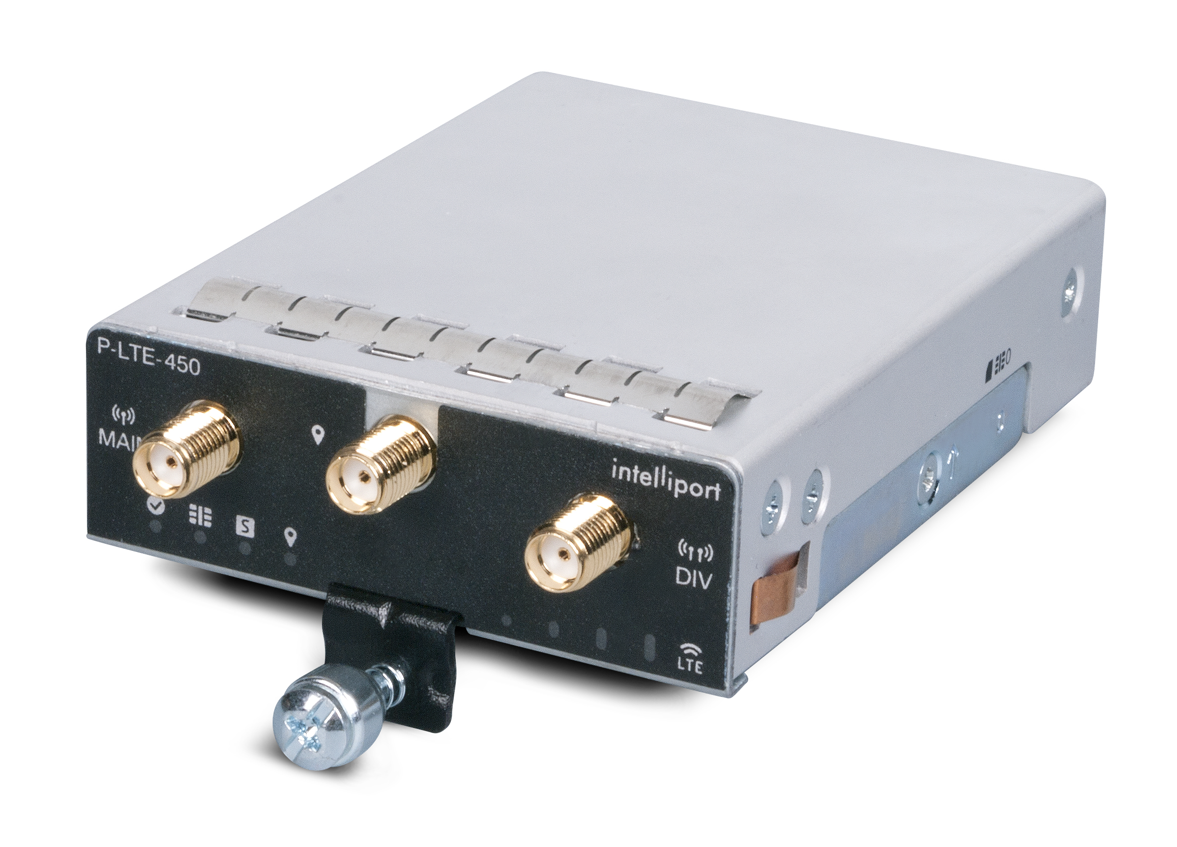
Figure 1. P-LTE-450 Pluggable Module

Note


Throughout the documentation, you will see the module referred to as P-LTE-450, which is the Cisco product name. The module is by Intelliport, which refers to it as the IPS-701. Both names will be present in documentation.

Unlike regular LTE modules, there are some differences with regards to the P-LTE-450 MHz on IOS-XE platform. Some of the key differences are:

  • IP pass through will be on the Gigabit Ethernet interfaces rather than the cellular interface.

  • Minimum P-LTE-450 cellular configuration may be done through Cisco IOS-XE config mode under Gigabit Ethernet 0/x/0 interface through lte 450 xxx commands.

  • Troubleshooting commands are from the IPS-701 web interface from Intelliport.

See the Intelliport product website for more information.

For additional information, see the LTE 450 MHz Alliance.

P-LTE-450 Hardware Features Overview

The P-LTE-450 Pluggable Interface Module offers the following features:

  • Available only on the IR1101 with Cisco IOS XE release 17.12.1 and later.

  • LTE 450 MHz band 31 and 72 with supported bandwidths of 1.4, 3, and 5 MHz only. For modem details see UNI450 ML620EU modem.

  • The P-LTE-450 can be installed in the IR1101 Base or in the IRM-1100 Expansion Module attached through the Compute module slot (bottom side of the IR1101 Base). The IRM-1100 Expansion Module can NOT be installed on the Expansion module side (top side of the IR1101 Base). See the following figure that shows the Expansion and Compute Module locations.

  • One SIM card – 3FF format.

  • Two RF ports of cellular module (main and diversity) via SMA(f) connectors.

  • GPS connectivity via SMA(f) connector. No Cisco IOS-XE support equivalent to Cellular PIM for GPS features.

LED Description

The following image shows the P-LTE-450 Pluggable Interface Module LEDs.
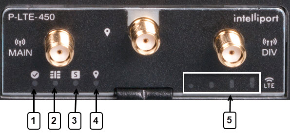
Figure 2. LED Description

1

Enabled

Green — Module power is on.

Off — System power is off.

2

SIM

Green — SIM inserted.

Off — No SIM.

3

Status

Green — Boot completed and connected to mobile internet.

Off — Has not booted.

4

GPS

Green — Enabled and has a valid location.

Off — Disabled.

5

RSSI

Signal Strength — See the Intelliport documentation for an exact description.

Thermal Considerations

The host router and the P-LTE-450 module is able to boot up and operate at a lower temperature than the radio module on the P-LTE-450. The radio module will not operate at a temperature below -30° C (-22° F).

P-LTE-450 Software Features Overview

The P-LTE-450 Pluggable Interface Module offers the following features:

  • Joint development by Cisco (IOS XE software) and Intelliport (Modem firmware).

  • The P-LTE-450 requires Network Advantage license to be recognized under Cisco IOS-XE. Refer to the Smart Licensing Using Policy (SLP).

  • The P-LTE-450 acts similarly to the Catalyst Cellular Gateway.

    • The modem is an IP passthrough for both IPv4 and IPv6 traffic.

    • The management interface, GigabitEthernet 0/1/0 (Base chassis), or GigabitEthernet 0/4/0 (Expansion Module), must be configured under Cisco IOS-XE.


      Note


      The configuration CLI applicable to the LTE-450 is under this interface.
    • Data traffic passes through GigabitEthernet 0/1/0.n or GigabitEthernet 0/4/0.n.

  • The P-LTE-450 is managed by a Web User Interface (WebUI) designed by Intelliport. Access to the Intelliport WebUI is gained through the Cisco WebUI. Requires IP routing for the management IP subnet.

  • GPS details will be shown only on the Intelliport modem IPS701 WebUI, not the IOS XE CLI.

  • Supports Multi PDN; each PDN is associated with the GigabitEthernet 0/x/0.n sub-interface.

The Intelliport Web User Interface is referred to as IPS701. This WebUI controls all configuration of the Pluggable Interface.

LTE 450 MHz Details

Channel bandwidth is variable at 1.4 MHz, 3 MHz, and 5 MHz . The maximum achievable is:

  • Bandwidth => 5 MHz

  • UL => 12.5 Mbps

  • DL => 37.5 Mbps

Additional information available at the LTE 450 MHz Alliance.

Showing the P-LTE-450 Installed in the Router

P-LTE-450 installed in the IR1101 Base chassis

Within the IR1101 base module, the interface enumerated will be GigabitEthernet 0/1/0 under the running configuration. The PIM module will reflect the respective sub-slot under show inventory.

The following example shows the P-LTE-450 installed in the IR1101 Base chassis:

IR1101#show inventory
+++++++++++++++++++++++++++++++++++++++++++++++++++++++++++++++++++++++
INFO: Please use "show license UDI" to get serial number for licensing.
+++++++++++++++++++++++++++++++++++++++++++++++++++++++++++++++++++++++

NAME: "Chassis", DESCR: "IR1101 Base Chassis"
PID: IR1101-K9   , VID: V01, SN: FCW2252007Y

NAME: "Module 0 - Mother Board", DESCR: "Cisco IR1101 motherboard"
PID: IR1101-K9   , VID: V01, SN: FOC22500RGS

NAME: "module subslot 0/0", DESCR: "IR1101-ES-5"
PID: IR1101-ES-5  , VID: V01, SN:     

NAME: "subslot 0/0 transceiver 0", DESCR: "10/100/1000BaseTX SFP"
PID: SFP-VADSL2+-I  , VID: V01, SN: MET20230010  

NAME: "module subslot 0/1", DESCR: "P-LTE-450 Module"
PID: P-LTE-450   , VID: V03, SN: S62EG000014
IR1101#

The following example shows the P-LTE-450 Ethernet configuration in the IR1101 Base chassis.

  • GI0/1/0 IP address is the P-LTE-450 management address.

    GI0/1/0.1 IP address is one received from the cellular network.

IR1101#show ip inter brief
Interface              IP-Address      OK? Method Status                Protocol
GigabitEthernet0/0/0   unassigned      YES NVRAM  administratively down down
FastEthernet0/0/1      unassigned      YES unset  down                  down
FastEthernet0/0/2      unassigned      YES unset  down                  down
FastEthernet0/0/3      unassigned      YES unset  down                  down
FastEthernet0/0/4      unassigned      YES unset  down                  down
GigabitEthernet0/1/0   192.168.200.128   YES DHCP   up                    up
GigabitEthernet0/1/0.1 192.168.2.15    YES DHCP   up                    up
Async0/2/0             unassigned      YES unset  up                    down
Loopback0              1.1.1.1         YES NVRAM  up                    up
VirtualPortGroup1      192.168.30.1    YES NVRAM  up                    up
Vlan1                  192.168.20.1    YES NVRAM  up                    down

IR1101#

The following shows the physical interface enumerated:

Router#sh interface gigabitEthernet 0/1/0
 GigabitEthernet0/l/0 is up, line protocol is up
   Hardware is P-LTE-450, address is ac3a.677f.a888 (bia ac3a.677f.a888) 
   Internet address is 192.168.200.128 
   MTU 1500 bytes, BW 1000000 Kbit/sec, DLY 10 usec, 
    reliability 255/255, txload 1/255, rxload 1/255 
   Encapsulation 802.IQ Virtual LAN, Vlan ID 1., loopback not set 
   Keepalive not supported 
   Full Duplex, 1000Mbps, link type is force-up, media type is RJ45 
   output flow-control is on, input flow-control is on 
   ARP type: ARPA, ARP Timeout 04:00:00
   Last input 03:30:21, output 00:00:06, output hang never 
   Last clearing of "show interface" counters never
   Input queue: 0/375/0/0 (size/max/drops/flushes); Total output drops: 0 
   Queueing strategy: fifo 
   Output queue: 0/40 (size/max)
   5 minute input rate 0 bits/sec, 0 packets/sec 
   5 minute output rate 0 bits/sec, 0 packets/sec 
     821 packets input, 115274 bytes, 0 no buffer
     Received 24 broadcasts (0 IP multicasts)
     0 runts, 0 giants, 0 throttles
     0 input errors, 0 CRC, 0 frame, 0 overrun, 0 ignored
     0 watchdog, 0 multicast, 0 pause input
     21279 packets output, 8622685 bytes, 0 underruns

The P-LTE-450 installed in the IR1101 Base chassis is connected through Gigabit Ethernet 0/1/0 and sub-interface.

P-LTE-450 installed in the IR1101 Expansion Module

Within the IR1101 expansion module connected on the Compute side, the interface enumerated will be GigabitEthernet 0/4/0 under running configuration and PIM module will reflect to respective sub-slot under show inventory.

The following example shows the P-LTE-450 installed in the IR1101 Expansion Module installed on the Compute (bottom) side:

IR1101#show inventory
+++++++++++++++++++++++++++++++++++++++++++++++++++++++++++++++++++++++
INFO: Please use "show license UDI" to get serial number for licensing.
+++++++++++++++++++++++++++++++++++++++++++++++++++++++++++++++++++++++
NAME: "Chassis", DESCR: "IR1101 Base Chassis"
PID: IR1101-K9         , VID: V01  , SN: FCW2252007Y
 
NAME: "Module 0 - Mother Board", DESCR: "Cisco IR1101 motherboard"
PID: IR1101-K9         , VID: V01  , SN: FOC22500RGS
 
NAME: "module subslot 0/0", DESCR: "IR1101-ES-5"
PID: IR1101-ES-5       , VID: V01  , SN:
 
NAME: "subslot 0/0 transceiver 0", DESCR: "10/100/1000BaseTX SFP"
PID: SFP-VADSL2+-I       , VID: V01  , SN: MET20230010
 
NAME: "module subslot 0/4", DESCR: "P-LTE-450 Module"
PID: P-LTE-450         , VID: V03  , SN: S62EG000014
 
NAME: "Module 2 - Compute Module", DESCR: "IR1100 expansion module with Pluggable slot, SFP, mSATA SSD slot and Digital GPIO"
PID: IRM-1100-SPMI     , VID: V01  , SN: FCW2329001L
IR1101#

The following example shows the P-LTE-450 Ethernet configuration in the IR1101 Expansion Module connected through Gigabit Ethernet 0/4/0 and sub-interface:

IR1101#show ip inter brief
Interface              IP-Address      OK? Method Status                Protocol
GigabitEthernet0/0/0   unassigned      YES NVRAM  administratively down down    
FastEthernet0/0/1      unassigned      YES unset  down                  down    
FastEthernet0/0/2      unassigned      YES unset  down                  down    
FastEthernet0/0/3      unassigned      YES unset  down                  down    
FastEthernet0/0/4      unassigned      YES unset  down                  down    
Cellular0/1/0          10.41.96.60     YES IPCP   up                    up      
Cellular0/1/1          unassigned      YES NVRAM  administratively down down    
GigabitEthernet0/4/0   192.168.200.128    YES DHCP   up                    up      
GigabitEthernet0/4/0.1 192.168.2.15   YES DHCP   up                    up      
Async0/2/0             unassigned      YES unset  up                    down    
Loopback0              1.1.1.1         YES NVRAM  up                    up      
VirtualPortGroup1      192.168.30.1    YES NVRAM  up                    up      
Vlan1                  192.168.20.1    YES NVRAM  up                    down 

The following shows the physical sub-interface enumerated:

Router#show interface gigabitEthernet 0/4/0 
GigabitEthernet0/4/0 is up, line protocol is up
   Hardware is P-LTE-450, address is ac3a.677f.a888 (bia ac3a.677f.a888) 
   Internet address is 192.168.200.128
   MTU 1500 bytes, BW 1000000 Kbit/sec, DLY 10 usec, 
     reliability 255/255, txload 1/255, rxload 1/255 
   Encapsulation 802.IQ Virtual LAN, Vlan ID 2.
   ARP type: ARPA, ARP Timeout 04:00:00 
   Keepalive not supported 
   Last clearing of "show interface" counters never

Gigabit Ethernet Configuration for the P-LTE-450

The router needs to have a basic Ethernet configuration in order for the P-LTE-450 to work. The Gigabit Ethernet 0/x/0 interface and the Gigabit Ethernet 0/x/0.x sub-interface need to be configured. There must be one sub-interface per PDN. The P-LTE-450 supports up to three PDNs, each on a different sub-interface.

The following are the requirements:

  • Gigabit Ethernet 0/x/0 interface is used for management of the P-LTE-450.

    • IPv4 address is learnt through DHCP, IPv6 address learnt through stateless autoconfiguration from the P-LTE-450.

  • Gigabit Ethernet 0/x/0.x sub-interface get its IP address from the Cellular network, once a SIM card is installed and Cellular attachment is done.

    • LTE 450 MHz PIM acts as IP passthrough.

    • NAT rules to be properly defined according to the network.

  • Default IP route to be configured according to the network.

  • Dot1Q Encapsulation for sub-interface.

  • NTP must be configured, enabling the P-LTE-450 to sync-up its clock with the router.

The following is an example of the minimum configuration needed:

interface GigabitEthernet0/1/0
 description Management Interface
 ip dhcp client lease 0 0 2
 ip address dhcp
 ip nat inside
 negotiation auto
 ipv6 address dhcp
 ipv6 enable
!
interface GigabitEthernet0/1/0.1
 description LTE450 Interface
 encapsulation dot1Q 2
 ip address dhcp
 ip dhcp client lease 0 0 2 
 ipv6 address autoconfig
 ipv6 enable
 ntp broadcast

ntp master

Configuring the Router Interface for the P-LTE-450 Module

LTE 450 MHz network IP pass through will be on the physical interface that is enumerated based on where module is connected, and address allocation is accomplished using DHCP either on IPv4 or IPv6. To connect to web-interface of P-LTE-450 MHz PIM module, need to have a sub-interface associated to the main physical interface with encapsulation dot1q.

The following steps are needed to configure the router to accept the P-LTE-450 Module. The module configuration can only be accomplished through the Intelliport WebUI.

Procedure

  Command or Action Purpose

Step 1

enable

Example:

Router> enable
Router#

Enables privileged EXEC mode.

  • Enter your password if prompted.

Step 2

configure terminal

Example:

Router> configure terminal
Enter configuration commands, one per line. End with CNTL/Z.
Router(config)#

Enables privileged EXEC mode.

  • Enter your password if prompted.

Step 3

interface GigabitEthernet <slot>

Example:

Router(config)# interface GigabitEthernet0/1/0
Router(config-if)#

Enter interface configuration mode either 0/1/0 or 0/4/0 based on connection.

Step 4

ip address dhcp

Example:

Router(config-if)#ip address dhcp
Router(config-if)#

DHCP configuration for IPv4 for main interface to retrieve the management address.

Step 5

ip nat inside

Example:

Router(config-if)#ip nat inside
Router(config-if)#

NAT configuration to connect to management WebUI.

Step 6

negotiation auto

Example:

Router(config-if)#negotiation auto
Router(config-if)#

To handle different speeds on hardware.

Step 7

ipv6 enable

Example:

Router(config-if)#ipv6 enable
Router(config-if)#

Enable IPv6 configuration for interface level.

Step 8

no shutdown

Example:

Router(config-if)#no shutdown
 Router(config-if)#

Remove “admin” shutdown on the interface.

Configuring the Router Sub-Interface for the P-LTE-450 Module

The following is an example of the sub-interface configuration to connect to WebUI of third party PIM module.

Procedure

  Command or Action Purpose

Step 1

enable

Example:

Router> enable
Router#

Enables privileged EXEC mode.

  • Enter your password if prompted.

Step 2

configure terminal

Example:

Router> configure terminal
Enter configuration commands, one per line. End with CNTL/Z.
Router(config)#

Enables privileged EXEC mode.

  • Enter your password if prompted.

Step 3

ipv6 unicast-routing

Example:

Router(config)# ipv6 unicast-routing
Router(config)#

IPv6 unicast-routing to be enabled.

Step 4

interface GigabitEthernet<slot>

Example:

Router(config)# interface GigabitEthernet0/1/0.1
Router(config-if)#

Creates a sub-interface associated to physical interface.

Step 5

Encapsulation dot1q <VLAN_ID>

Example:

Router(config-if)#encapsulation dot1q 2
Router(config-if)#

Enables encapsulation VLAN ID for the sub-interface.

Step 6

ip address dhcp

Example:

Router(config-if)#ip address dhcp
Router(config-if)#

Obtains the cellular network IP address.

Step 7

ip nat inside

Example:

Router(config-if)#ip nat inside
 Router(config-if)#

NAT configuration to connect to WebUI.

Step 8

no shutdown

Example:

Router(config-if)#no shutdown
 Router(config-if)#

Remove “admin” shutdown on the interface.

Configuration Example

The following is a configuration example on the IR1101 Base unit.

Router#show running-config interface GigabitEthernet 0/1/0
Building configuration...

Current configuration : 105 bytes
!
interface GigabitEthernet0/1/0
ip address dhcp
negotiation auto
ipv6 address dhcp
ipv6 enable
end

Router#show running-config interface GigabitEthernet 0/1/0.1
Building configuration...

Current configuration : 112 bytes
!
interface GigabitEthernet0/1/0.1
encapsulation dot1Q 2
ip address dhcp
ipv6 address dhcp
ipv6 enable
end

# No VLAN 2 required for dot1q 2 above

Note


The default WebUI IP address can only be changed through the WebUI once the initial configuration is done, since you need IP access to the module.

Example Topology

The WebUI connection for the P-LTE-450 MHz module can be dependent on network topology based on the following diagram:

Figure 3. WebUI Connection for P-LTE-450 MHz Module Topology

Refer to the following table for details on the topology.

1

The GI 0/1/0 (or GI0/4/0) interface is used for management. It communicates between IOS XE and the P-LTE-450.

2

The IP address from the cellular network is passed through from the modem to GI0/1/0.n subinterface. There is one per active PDN.

3

GI0/1/0.1 Cellular interface PDN1. The LTE450MHz carrier assigns an IP address to the LTE 450 modem that is passed through to GI0/1/0.1 sub-interface.

4

P-LTE450 WebUI access:

1 ping 192.168.200.1

2 open WebUI

These are the possible connections:

  1. Connection using Local-PC

  2. Connection using Remote-PC

With connection using Local-PC (1), there is no need for ip nat configuration.

With connection using Remote-PC (2), nat configuration is required based on the network topology.

In either case, you enter the URL of the Management IP address for the P-LTE-450 MHz module (192.168.200.1 is the default) or re-direct to the IP address from the Cisco WebUI.

Configuring Minimum P-LTE-450 Parameters through Cisco IOS-XE

There is an IOS-XE configuration command line under the Gigabit Ethernet 0/x/0 interface that provides a subset of LTE 450 configuration that allows a management solution to set template.

This subset includes the following:

  • Band

  • DHCP default gateway

  • Profile (including the following)

    • APN

    • Mode

    • Authentication

    • VLAN

The following are command examples:

IR1101#conf term
Enter configuration commands, one per line.  End with CNTL/Z.

IR1101(config)#inter gi0/4/0

IR1101(config-if)#lte450 ?
  band                  select band <31|72>
  dhcp_default_gateway  select <Assign|Don't assign>
  profile               LTE Profile management commands

IR1101(config-if)#lte450 profile id 1 apn TEST authentication ?
  chap  CHAP authentication only
  none  No authentication
  pap   PAP authentication only

IR1101(config-if)#lte450 profile id 1 apn TEST authentication none pdn-type ?
  ipv4    IPv4 type bearer
  ipv4v6  IPV4V6 type bearer
  ipv6    IPV6 type bearer

IR1101(config-if)#lte450 profile id 1 apn TEST authentication none pdn-type ipv4 vlan ?
  <1-4094>  ltebridge profile VLAN ID
  <cr>      <cr>

IR1101(config-if)#lte450 profile id 1 apn TEST authentication none pdn-type vlan 2 ?
  disable  disable Profile 
  enable   enable profile 
  <cr>     <cr>

IR1101(config-if)#lte450 profile id 1 apn TEST authentication none pdn-type vlan 2 enable

Managing the P-LTE-450 Through the WebUI

The P-LTE-450 is managed by the Web User Interface designed by Intelliport. Access to the Intelliport WebUI is gained through the Cisco WebUI.

Cisco WebUI to Intelliport WebUI Redirection

Launch the Cisco WebUI and log in with your IOS XE credentials (privilege 15).

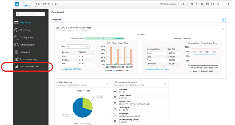
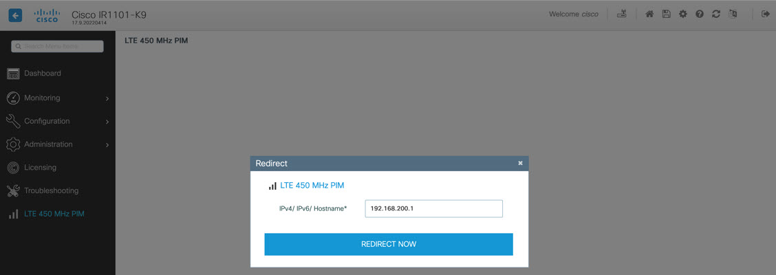
Click on LTE 450 MHz PIM along the left side. The Redirect window appears.

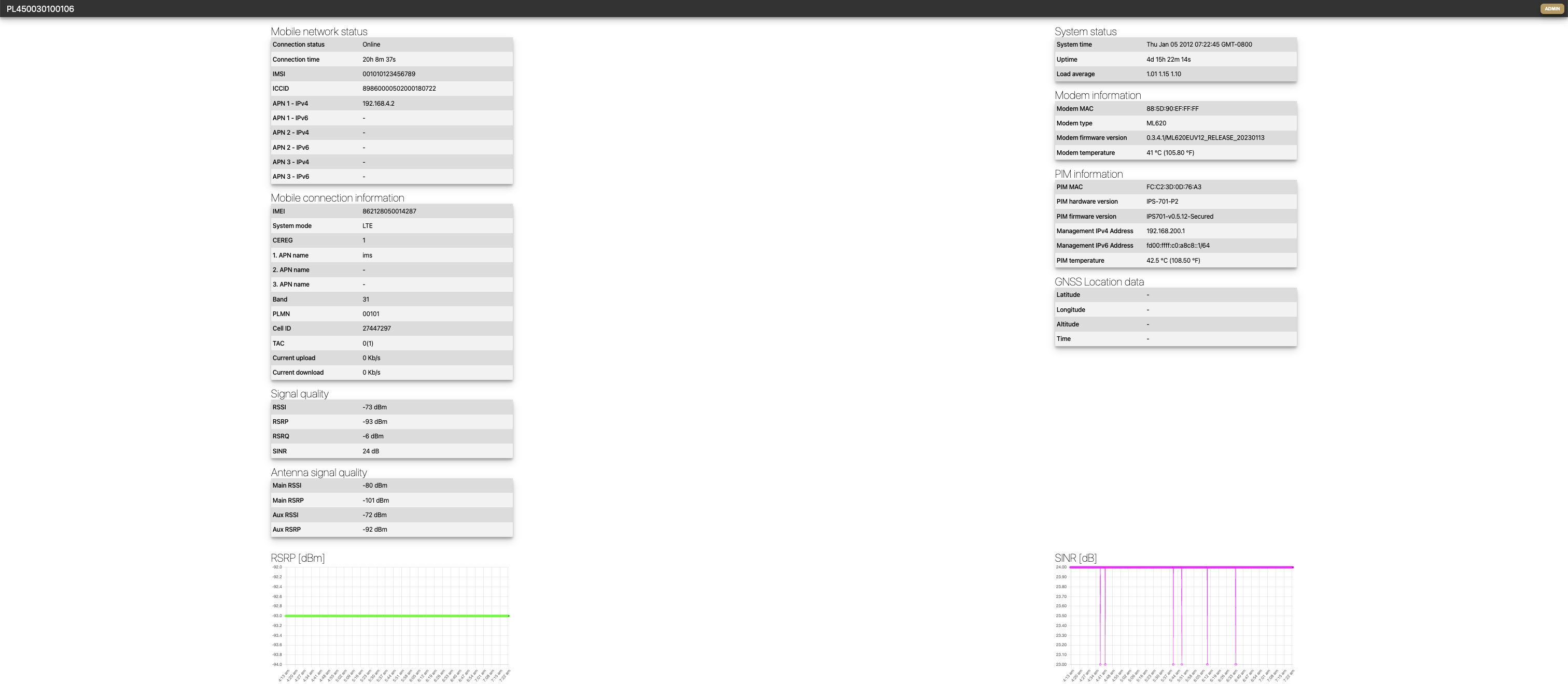
Enter the IP address of the LTE PIM. This address must be pingable by your laptop. Then click REDIRECT NOW. The Intelliport WebUI, referred to as the IPS701, landing page appears.

IPS701 WebUI Landing Page

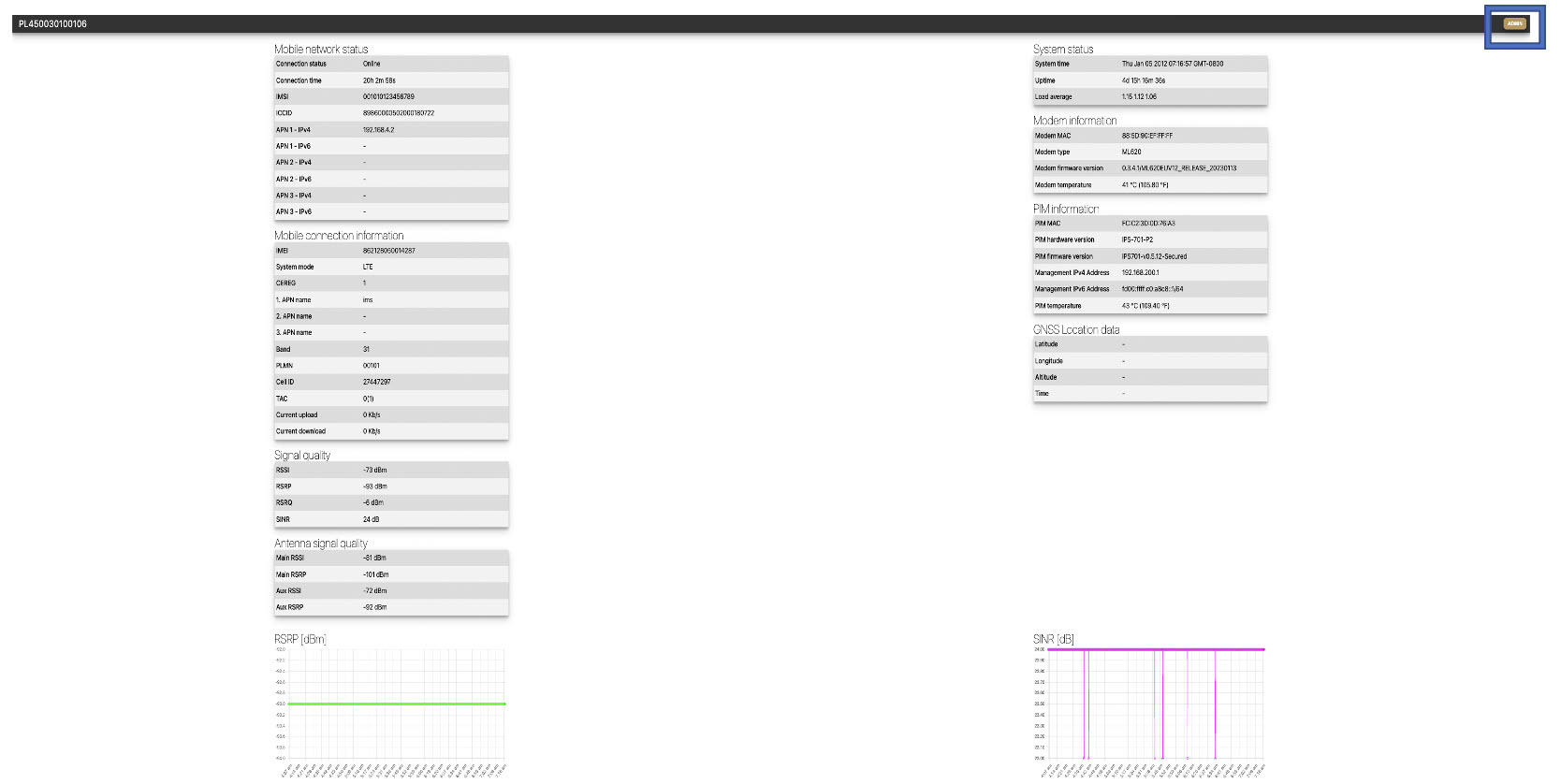
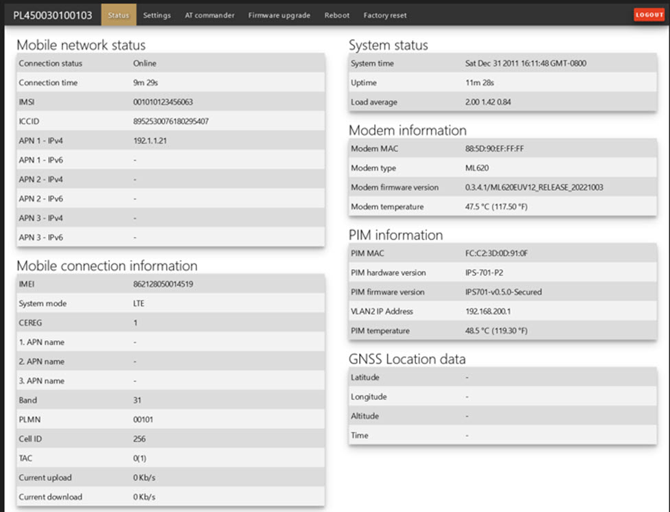
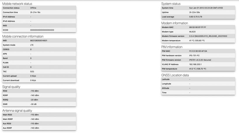
The landing page shows all of the status information as well as radio signal graphs.

To log into the WebUI as Administrator, click on the ADMIN button on the top right corner.

Log in with the default credentials:

  • Username — admin

  • Password — admin


Note


Changing the default credentials is not supported for the current release of firmware from IPS701.

Then click on SUBMIT.

Configuring the IPS701

The Intelliport WebUI (IPS-701) appears when you log in as admin.

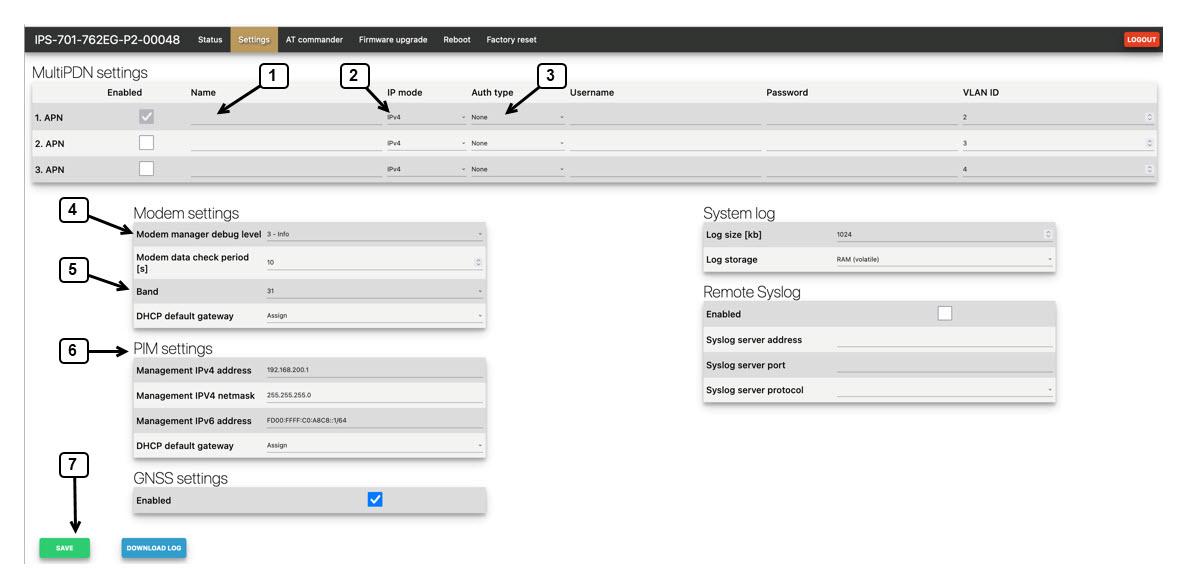
Click on the Settings tab to set the IPS701 parameters.

The following settings apply:

1

Select APN and enter an APN name.

2

Select IPv4, IPv6, or both.

3

Select Authentication. PAP, CHAP, or None.

4

Modem Manager debug level:

1 — error

2 — debug

3 — info

5

Select LTE 450 MHz band B31 or B72.

6

IPv4 and IPv6 address and subnet for Management.

7

Click SAVE to save the configuration.

Reboot the P-LTE-450.


Note


Settings will be applied after saving the configuration, however, you must do an additional shut and no shut on the physical interface on the router.

Other Functions

If new IPS701 firmware becomes available, it can be upgraded from the IPS701 WebUI. Click on the Firmware upgrade tab.

Choose the appropriate PIM or Modem firmware and upload it. Once the new firmware is uploaded click on the UPGRADE button.

The Reboot option in the IPS701 WebUI reloads the modem (not the PIM in IOS XE).

The P-LTE-450 module can also be rebooted through Cisco IOS-XE by performing a power-cycle of the module. Use the hw-module subslot <slot> shutdown unpowered command.

IR1101#conf term
Enter configuration commands, one per line. End with CNTL/Z.
IR1101(config)#hw-module subslot 0/1 shutdown unpowered
IR1101(config)#no hw-module subslot 0/1 shutdown unpowered

If the IPS701 needs to be reset to factory defaults, it should be done through the WebUI.

Enter the admin password and then click FACTORY RESET.

Additional CLI Support for the P-LTE-450

Management of the module is from a WebUI by Intelliport, which refers to it as the IPS-701. There is a subset of CLI commands available that are in the IPS-701 WebUI..

P-LTE-450 Monitoring

The CLI will show the module status information which is available from the IPS-701 WebUI minus the signal radio graphs.

Figure 4. IPS-701 Landing Page

The show commands will either display all sections or based on the qualifier matching each section.

Router# show lte450 0/1/0 ?
  all       Display all LTE450 information
  hardware  Display LTE450 hardware information
  network   Display LTE450 network information
  radio     Display LTE450 radio information

Router#show lte450 0/1/0 all

System Status
=============
System time = Tue Jul 11 19:59:59 2023
Uptime = 9d 0h 27m 46s
Load Average = 3.14 3.05 3.04

Modem information
=================
Modem MAC = 88:5D:90:EF:FF:FF
Modem hardware version = ML620EU
Modem firmware version = 0.3.4.1/ML620EUV12_RELEASE_20230424
Modem temperature = 50.0 deg C

PIM information
===============
PIM MAC = FC:C2:3D:0D:7E:82
PIM hardware version = IPS-701-P3
PIM firmware version = IPS701-v1.1.0-Secured
PIM serial number = 762EG000085
Management IPv4 Address = 192.168.200.1
Management IPv6 Address = fd00:ffff:c0:a8c8::1/64
PIM temperature = 52.0 deg C

GNSS Location Data
==================
Latitude = 37.4183466
Longitude = -121.9192633
Altitude = 18.30 m
Time = 2023-07-11T20:02:43.000Z

Watchdog Statistics
===================
Hardware watchdog counter = 0
Modem watchdog counter = 2

Mobile network status
=====================
Connection Status = Online
Connection time = 3d 1h 44m 7s
IMSI = 123456700004864
ICCID = 8949001508130014864
MSISDN = 
APN-1 IPv4 address = 192.168.168.19
APN-1 IPv6 address = 
APN-2 IPv4 address = 
APN-2 IPv6 address = 
APN-3 IPv4 address = 
APN-3 IPv6 address = 

Mobile connection information
=============================
IMEI = 862128050014592
System mode = LTE
EPS State = ATTACHED
RRC State = RRC CONNECTED
CEREG = 5
APN-1 APN name = cmw500
APN-2 APN name = 
APN-3 APN name = 
Band = 31
PLMN = 00101
Cell ID = 256
TAC = 0(1)
PCI = 0
TX power = -15
Bandwidth = 5MHz
LTE RX channel = 9895
LTE TX channel = 27785
Current upload = 1501.0 Kbps
Current download = 1655.0 Kbps

Signal quality
==============
RSSI = -64 dBm
RSRP = -91 dBm
RSRQ = -13 dBm
SINR = 30 dB

Antenna signal quality
======================
Main RSSI = -64 dBm
Main RSRP = -91 dBm
Aux RSSI = -63 dBm
Aux RSRP = -90 dBm

Router#show lte450 0/1/0 hardware 

System Status
=============
System time = Tue Jul 11 20:00:28 2023
Uptime = 9d 0h 28m 15s
Load Average = 3.31 3.09 3.05

Modem information
=================
Modem MAC = 88:5D:90:EF:FF:FF
Modem hardware version = ML620EU
Modem firmware version = 0.3.4.1/ML620EUV12_RELEASE_20230424
Modem temperature = 50.0 deg C

PIM information
===============
PIM MAC = FC:C2:3D:0D:7E:82
PIM hardware version = IPS-701-P3
PIM firmware version = IPS701-v1.1.0-Secured
PIM serial number = 762EG000085
Management IPv4 Address = 192.168.200.1
Management IPv6 Address = fd00:ffff:c0:a8c8::1/64
PIM temperature = 52.0 deg C

GNSS Location Data
==================
Latitude = 37.4183466
Longitude = -121.9192633
Altitude = 18.30 m
Time = 2023-07-11T20:03:06.000Z

Watchdog Statistics
===================
Hardware watchdog counter = 0
Modem watchdog counter = 2


Router#show lte450 0/1/0 network 

Mobile network status
=====================
Connection Status = Online
Connection time = 3d 1h 45m 18s
IMSI = 123456700004864
ICCID = 8949001508130014864
MSISDN = 
APN-1 IPv4 address = 192.168.168.19
APN-1 IPv6 address = 
APN-2 IPv4 address = 
APN-2 IPv6 address = 
APN-3 IPv4 address = 
APN-3 IPv6 address = 

Mobile connection information
=============================
IMEI = 862128050014592
System mode = LTE
EPS State = ATTACHED
RRC State = RRC CONNECTED
CEREG = 5
APN-1 APN name = cmw500
APN-2 APN name = 
APN-3 APN name = 
Band = 31
PLMN = 00101
Cell ID = 256
TAC = 0(1)
PCI = 0
TX power = -15
Bandwidth = 5MHz
LTE RX channel = 9895
LTE TX channel = 27785
Current upload = 1577.0 Kbps
Current download = 1739.0 Kbps

Router#show lte450 0/1/0 radio

Signal quality
==============
RSSI = -64 dBm
RSRP = -91 dBm
RSRQ = -13 dBm
SINR = 30 dB

Antenna signal quality
======================
Main RSSI = -64 dBm
Main RSRP = -91 dBm
Aux RSSI = -63 dBm
Aux RSRP = -90 dBm

P-LTE-450 Configuration

Command line options are available for the following parameters:

  • Band

  • DHCP Default Gateway

  • APN Profile

Configuration options are shown by the lte450 ? command.

Router#conf t
Enter configuration commands, one per line.  End with CNTL/Z.
(config)#interface GigabitEthernet 0/1/0
(config-if)#lte450 ?
band                  select band <31|72>
dhcp_default_gateway  select <Assign|Don't assign>
profile               LTE Profile management commands

The following are examples of the CLI options.

Table 1. CLI Options for Band and DHCP Default Gateway

Option

Command

Purpose

Band

lte450 band <31 | 72>

Assigns the modem band.

DHCP Default Gateway

lte450 dhcp_default_gateway <assign | dont-assign>

Assigns/Unassigns DHCP default gateway.

CLI options for the APN Profile are broken down in the following table:

Table 2. CLI Options for APN Profile

Profile Parameter

Command

Options

APN Name

lte450 profile id <1-3> apn <apn-name>

Assigns a name to the apn belonging to a particular profile.

  • <1-3> Profile number

  • <apn-name> Name of access point

Authentication

lte450 profile id <1-3> authentication <chap | none | pap> username <Username> password <Password>

Specifies the type of authentication to be used for a particular profile. If the authentication type is chap/pap, username and password fields will be required. If the authentication type is none, username and password fields will not be required.

  • <chap> CHAP authentication only

  • <none> No authentication

  • <pap> PAP authentication only

IP Mode

lte450 profile id <1-3> pdn-type <ipv4/ipv4v6/ipv6>

Specifies the IP mode for a particular profile.

  • <ipv4> IPv4 type bearer

  • <ipv4v6> IPV4V6 type bearer

  • <ipv6> IPV6 type bearer

VLAN

lte450 profile id <1-3> vlan <1-4094> <disable | enable>

VLAN: Assigns a VLAN ID to a particular lte bridge profile.

  • <1-4094> ltebridge profile VLAN ID

Troubleshooting

When troubleshooting with a private LTE Network, the router software configuration is limited. In order to troubleshoot the module, you need to download a log from the IPS-701 module for third party evaluate of the state of the connection.

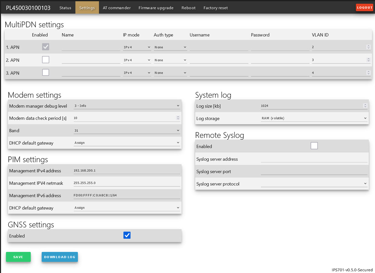
In order to download the log from the IPS-701 webpage, navigate to the Settings tab. Click on DOWNLOAD LOG. If you want to increase the logging buffer you can do the same on the webpage.

Refer to the following:

Figure 5. Download Log

To reload the module, use the hw-module sublot <slot> command with reload option:

Router#hw-module subslot 0/1 ?
maintenance Maintenance mode
oir Spa OIR
reload Restart the target subslot
start Activate the target subslot
stop Deactivate the target subslot

Router#hw-module subslot 0/1 reload