Intersite L3Out with PBR

Intersite L3Out with PBR

Cisco Application Centric Infrastructure (ACI) policy-based redirect (PBR) enables traffic redirection for service appliances, such as firewalls or load balancers, and intrusion prevention system (IPS). Typical use cases include provisioning service appliances that can be pooled, tailored to application profiles, scaled easily, and have reduced exposure to service outages. PBR simplifies the insertion of service appliances by using contract between the consumer and provider endpoint groups even if they are all in the same virtual routing and forwarding (VRF) instance.

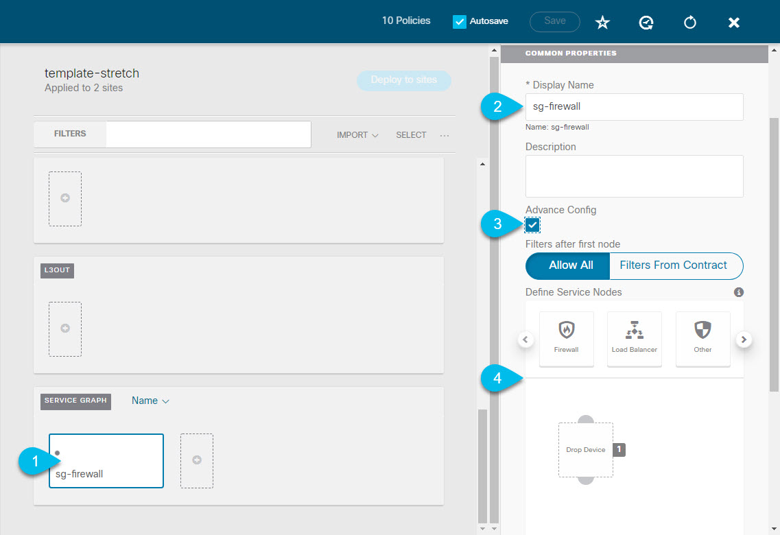
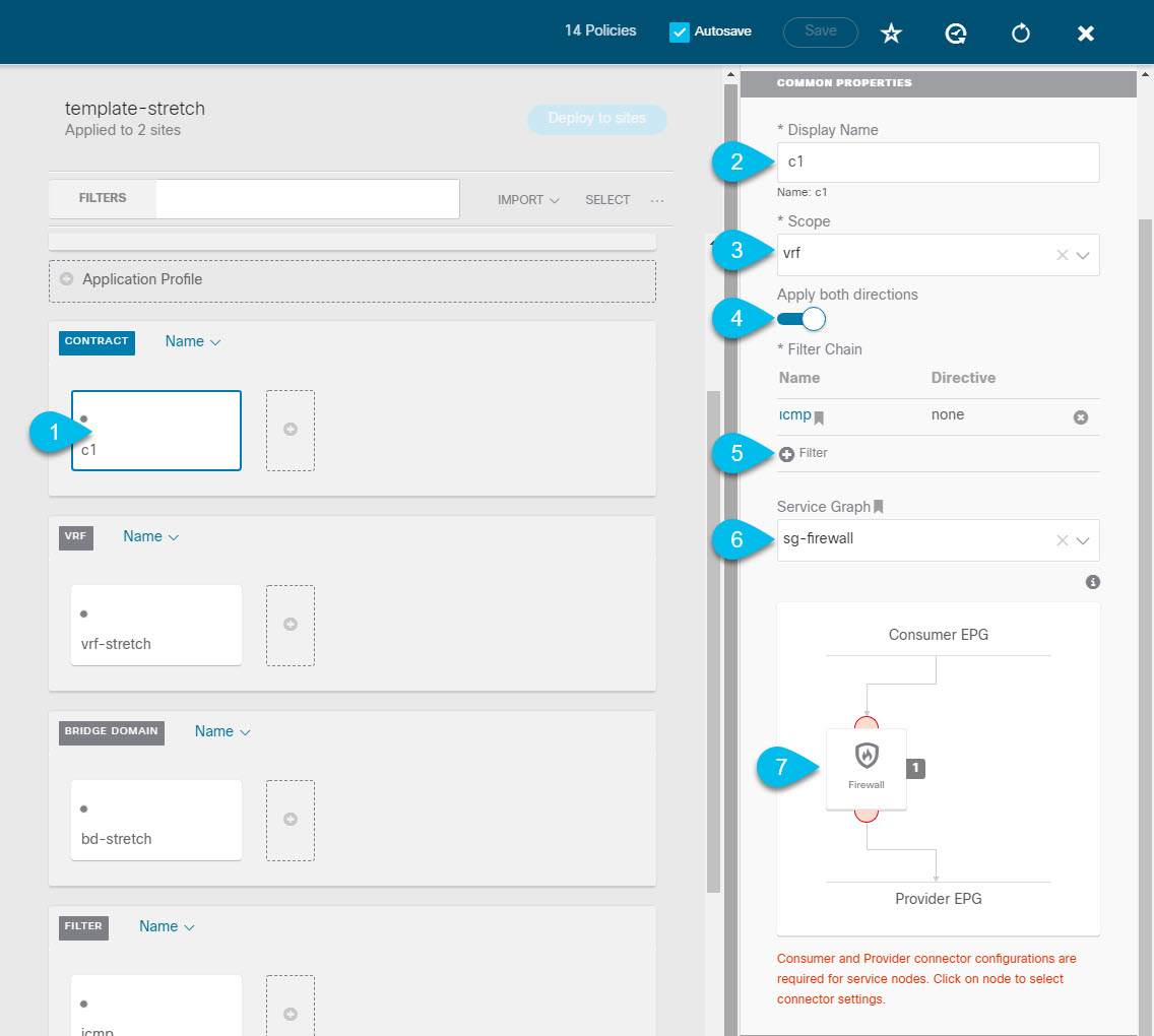
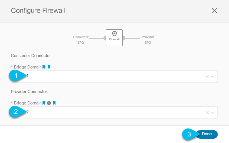
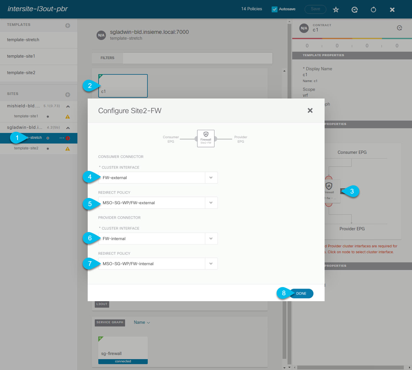
PBR deployment consists of configuring a route redirect policy and a cluster redirect policy, and creating a service graph template that uses these policies. After the service graph template is deployed, you can attach it to a contract between EPGs so that all traffic following that contract is redirected to the service graph devices based on the PBR policies you have created. Effectively, this allows you to choose which type of traffic between the same two EPGs is redirected to the L4-L7 device, and which is allowed directly.

More in-depth information specific to services graphs and PBR is available in the Cisco APIC Layer 4 to Layer 7 Services Deployment Guide

PBR Support in Multi-Site Deployments

Cisco Multi-Site has supported EPG-to-EPG (east-west) and L3Out-to-EPG (north-south) contracts with PBR since Cisco APIC, 
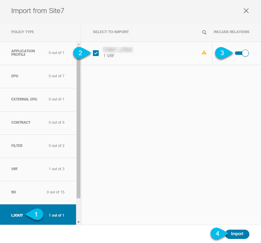
Release 3.2(1). However, the L3Out-to-EPG across sites (traffic from an external endpoint in site1 to an endpoint in site2) case was supported only if both sites had local L3Outs. The intersite L3Out use cases were limited to the examples and configurations described in the Intersite L3Out chapter. Similarly, the Service Graph integration with PBR but no intersite L3Out is described in great detail in the Cisco Multi-Site and Service Node Integration White Paper.

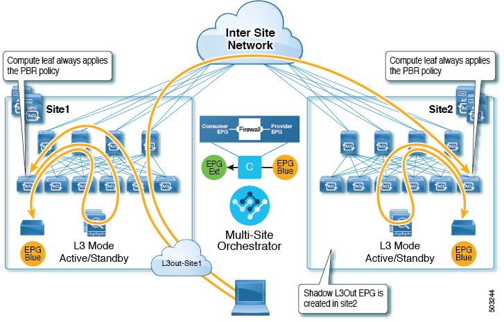
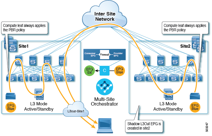
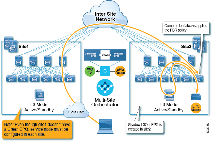
Starting with Cisco APIC, Release 4.2(5), the L3Out-to-EPG with PBR across sites (intersite L3Out) use case has been extended to support cases where the application EPG has no local L3Out or the local L3Out is down.

Supported Use Cases

The following diagrams illustrate the traffic flows between the an ACI internal endpoint in application EPG and an external endpoint through the L3Out in another site in the supported intersite L3Out with PBR use cases.

The workflow to configure these examples is the same, with the only differences being whether you create the objects in the same or different VRFs (inter-VRF vs intra-VRF) and where you deploy the objects (stretched vs non-stretched):

  1. Create the L4-L7 devices directly in the site's APIC, as described in Creating and Configuring L4-L7 Devices and PBR Policies.

    You cannot create the devices and PBR policies from the Nexus Dashboard Orchestrator, so you will need to log in to each site's APIC directly to configure those options.

  2. Create the required templates, as described in Creating Templates.

    We recommend creating a single stretched template that will contain all the objects deployed to all sites. Then an extra template for each site with the objects specific to that site only.

  3. Create and configure the service graph, as described in Configuring Service Graph.

  4. Create the contract and filter you will use for all traffic between the application EPG and the external EPG containing the L3Out in another site, as described in Creating Filter and Contract.

  5. Create the application EPG with its VRF and bridge domain, as described in Creating Application Profile and EPG.

    Depending on whether you plan to stretch the application EPG or not, you will create these objects in different templates. Similarly, you can choose to use the same or different VRFs for the application EPG and the L3Out.

  6. Create the L3Out, as described in Creating or Importing Intersite L3Out and VRF.

  7. Create the external EPG for the L3Out, as described in Configuring External EPG to Use Intersite L3Out.

Inter-VRF vs Intra-VRF

When creating and configuring the application EPG and the external EPG, you will need to provide a VRF for the application EPG's bridge domain and for the L3Out. You can choose to use the same VRF (intra-VRF) or different VRFs (inter-VRF).

When establishing a contract between the EPGs, you will need to designate one EPG as the provider and the other one as the consumer:

  • When both EPGs are in the same VRF, either one can be the consumer or the provider.

  • If the EPGs are in different VRFs, the external EPG must be the provider and the application EPG must be the consumer.

Stretched EPG

This use case illustrates a single application EPG that is stretched between two sites and a single L3Out created in only one of the sites. Regardless of whether the application EPG's endpoint is in the same site as the L3Out or the other site, traffic will go through the same L3Out. However, the traffic will always go through the service node that is local to the endpoint's site.


Note


The same flow applies in cases when the external EPG is stretched and each site has its own L3Out, but the L3Out in the site where the traffic is originating or is destined to is down.


Figure 1. Inbound Traffic
Figure 2. Outbound Traffic

Site-Local EPG

This use case illustrates a site-local application EPG that will use the L3Out in the other site for North-South traffic. Like in the previous example, all traffic will use the EPG's site-local service graph device.


Note


The same flow applies in cases where the external EPG is stretched and each site has its own L3Out, but the EPG's local L3Out is down.


Figure 3. Inbound Traffic
Figure 4. Outbound Traffic

Guidelines and Limitations

When configuring an Intersite L3Out with PBR, the following restrictions apply:

  • For intersite L3Out without PBR use cases, see Intersite L3Out

  • For intersite L3Out with PBR, the following use cases are supported:

    • Inter-VRF intersite L3Out with the application EPG as the consumer.

      For inter-VRF contracts, the L3Out must be the provider.

    • Intra-VRF intersite L3Out with the application EPG as either the provider or the consumer

    • Intersite transit routing (L3Out-to-L3Out) with PBR is not supported.

  • The above use cases are supported for sites running Cisco APIC, Release 4.2(5) or Release 5.1(x). They are not supported for sites running Cisco APIC, Release 5.0(x).

  • In all supported cases, the application EPG can be stretched or not stretched.

  • Service graph devices must be defined in each site, including the sites that don't have an application EPG that has a PBR contract with an intersite L3Out external EPG.

  • Both one-arm and two-arm deployment models are supported.

    In one-arm deployment, both the inside and outside interfaces of the service graph are connected to the same bridge domain. In two-arm deployments, the service graph interfaces are connected to separate BDs.

  • When configuring a load balancer with PBR, the load balancer and the real servers for the virtual IP (VIP) must be in the same site. If PBR is disabled, the load balancer and the real servers can be in different sites.

  • When configuring PBR, destination can be L1, L2, or L3.

Configuring APIC Sites

Configuring External TEP Pool

Intersite L3Out requires a external TEP address for the border leaf switches in each pod. If you already have an external TEP pool configured, for example for another feature such as Remote Leaf, the same pool can be used. The existing TEP pool will be inherited by the Nexus Dashboard Orchestrator and shown in the GUI as part of the infra configuration. Otherwise, you can add a TEP pool in the GUI, as described in this section.


Note


Every pod must be assigned a unique TEP pool and it must not overlap with any other TEP pool in the fabric


Procedure


Step 1

Log in to your Nexus Dashboard Orchestrator.

Step 2

From the left navigation pane, select Infrastructure > Infra Configuration.

Step 3

In the top right of the main pane, click Configure Infra.

Step 4

In the left sidebar, select the site you want to configure.

Step 5

In the main window, click a pod in the site.

Step 6

In the right sidebar, click +Add TEP Pool.

Step 7

In the Add TEP Pool window, specify the external TEP pool you want to configure for that site.

Note


You must ensure that the TEP pool you are adding does not overlap with any other TEP pools or fabric addresses.

Step 8

Repeat the process for each site and pod where you plan to use intersite L3Outs.


Creating and Configuring L4-L7 Devices and PBR Policies

You must create the service graph devices and define the PBR policies directly in each site's APIC.

Procedure


Step 1

Log in to your Cisco APIC.

Step 2

In the top menu bar, click Tenants, then select the tenant where you want to create the device.

Step 3

Create an L4-L7 device.

  1. In the left sidebar, expand <tenant-name> > Services > L4-L7 category.

  2. Right-click Devices category.

  3. Choose Create L4-L7 Devices.

    The Create L4-L7 Devices configuration dialog opens.

Step 4

Configure the L4-L7 device.

The following image shows a sample device configuration. Your configuration settings will depend on the type and purpose of the device.

Step 5

Create a PBR policy.

  1. In the left sidebar, expand <tenant-name> > Policies > Protocol category.

  2. Right-click L4-L7 Policy-Based Redirect category.

  3. Choose Create L4-L7 Policy-Based Redirect.

    The Create L4-L7 Policy-Based Redirect configuration dialog opens.

Step 6

Configure the PBR policy.

The following image shows a sample PBR policy configuration with destination IP and MAC added.

Your configuration settings will depend on the type and purpose of the device and policy you create. For example, you can configure additional options such as IP-SLA, hashing algorithm, resilient hashing, and so on in the PBR policy.

Step 7

Repeat the previous steps to create the required devices and PBR policies in the other site.


Creating Templates

When creating the schema and template, we recommend separating the templates in the following way:

  • A single shared template that will contain all the objects that are stretched between all sites.

  • One template per site that will contain the objects you will deploy to that site only.

In this example, we will work with two sites, so we will create a total of three templates: one for each site, plus one stretched.

Before you begin

You must have:

Procedure


Step 1

Log in to your Cisco Nexus Dashboard Orchestrator GUI.

Step 2

Create a new Schema.

  1. In the left navigation sidebar, expand the Application Management category.

  2. Choose Schemas.

  3. Click Add Schema to create a new schema.

The Edit Schema window will open.

Step 3

Name the Schema and pick the Tenant.

  1. Replace Untitled Schema with the name for your schema.

    Simply click on the Untitled Schema name to edit it.

  2. Rename the template.

    In the left sidebar, mouse over the template and click the Edit icon.

    For example, template-stretched.

  3. In the main pane, click To build your schema please click here to select a tenant.

  4. In the right sidebar, click the Select a Tenant dropdown.

  5. Select the tenant.

Step 4

Create any additional templates.

In the left sidebar, click the plus (+) icon next to Templates to add the site-specific templates. Then follow the same instructions described in the previous steps to name the templates and pick the tenant.

For example, template-site1 and template-site2.


Configuring Service Graph

You must have:

This section describes how to configure one or more devices for a service graph.

Procedure


Step 1

Select the template where you will create the service graph.

You will create a single service graph in the template-stretch but configure site-local devices for it as described later in this procedure.

Step 2

Create the Service Graph.

  1. In the main pane, scroll down to the Service Graph area and click the + sign to create a new one.

  2. Provide the Display Name for the service graph.

  3. (Optional) Check the Advanced Config option.

    This option allows you to configure whether traffic is restricted or not after the first service graph node. If you do not enable this option, all traffic is allowed after the first service graph node by default.

    If you choose to enable the Advanced Config, select one of the following two options:

    • Allow All: Use default (permit-all) filter instead of specific filter from contract subject.

      This is the same behavior as with Advanced Config disabled.

    • Filters From Contract: Use specific filters from contract subject.

  4. In the right sidebar, scroll down to the Define Service Nodes area and drag and drop one or more nodes into the Drop Device box.

    Multi-Site supports up to two nodes per service graph.

Step 3

Configure service graph's site-local devices.

You must perform this step for every site that is part of the Multi-Site domain.

  1. From the left sidebar, select one of the sites where you will deploy this service graph.

  2. In the main pane, select the service graph you created.

  3. In the right sidebar, click on the service graph node.

  4. In the Select Device Details window, choose the device you have created in the site's APIC.


Creating Filter and Contract

You must have:

  • Created the templates where you will create these objects, as described in Creating Templates.

This section describes how to create a contract and filters that will be used for the traffic going between the application EPG and the L3Out through the service graph.

Procedure


Step 1

Create a filter.

  1. In the middle pane, scroll down to the Filter area, then click + to create a filter.

  2. In the right pane, provide the Display Name for the filter.

  3. In the right pane, click + Entry.

Step 2

Provide the filter details.

  1. Provide the Name for the filter.

  2. Choose the Ether Type and IP Protocol.

    For example, ip and icmp.

  3. Leave other properties unspecified.

  4. Click Save to save the filter.

Step 3

Create a contract

  1. In the middle pane, scroll down to the Contract area and click + to create a contract.

  2. In the right pane, provide the Display Name for the contract

  3. From the Scope dropdown menu, select the scope of the contract.

    If your application EPG and L3Out are in the same VRF, choose vrf; otherwise, if you are configure inter-VRF use case, select tenant.

  4. Ensure that Apply both directions is enabled.

    This allows you to use the same filter to apply for both consumer-to-provider and provider-to-consumer directions.

  5. In the right pane, scroll down to the Filter Chain area and click + Filter to add a filter to the contract.

    In the Add Filter Chain window that opens, select the filter you added in previous section from the Name dropdown menu.

    If you disabled the Apply both directions option, repeat this stem for the other filter chain.

  6. From the Service Graph dropdown, select the service graph you created in previous section.

  7. Click the service graph node to configure its connectors.

Step 4

Select bridge domains for the service graph nodes' connectors.

  1. Provide the Consumer Connector bridge domain.

  2. Provide the Provider Connector bridge domain.

  3. Click Done to save.

Step 5

Configure the contract's site-local properties.

  1. In the left sidebar, select the template under a site to which it is assigned.

  2. In the main pane, select the contract.

  3. In the right sidebar, click a service graph node.

  4. Select the Cluster Interface for the Consumer Connector.

  5. Select the Redirect Policy for the Consumer Connector.

  6. Select the Cluster Interface for the Provider Connector.

  7. Select the Redirect Policy for the Provider Connector.

  8. Click Done to save the changes.

  9. Repeat this step for every site.


Creating Application EPG

Creating VRF and Bridge Domain for Application EPG

This section describes how to create the VRF and bridge domain (BD) for your application EPG.

Before you begin

You must have:

  • Created the templates where you will create these objects, as described in Creating Templates.

Procedure


Step 1

Select the template where you will create the VRF and BD.

If you are planning to stretch the VRF and BD, select the template-stretch template. Otherwise, choose one of the site-specific templates.

Step 2

Create VRF.

  1. In the main pane's VRF area, click the plus (+) sign to add a VRF.

  2. In the right sidebar, provide the Display Name for the VRF.

  3. Specify other VRF settings as appropriate for your deployment.

Step 3

Create BD.

  1. In the main pane's BD area, click the plus (+) sign to add a BD.

  2. In the right sidebar, provide the Display Name for the BD.

  3. From the Virtual Routing & Forwarding dropdown, select the VRF you created in the previous step.

  4. Specify other BD settings as appropriate for your deployment.


Creating Application Profile and EPG

This section describes how to create the application EPG you will later configure to use the intersite L3Out with Service Graph.

Before you begin

You must have:

Procedure


Step 1

Select the template where you want to create the objects.

If you plan to stretch the application EPG, create it in the stretched template. If you application EPG is going to be site local, create it in the site-specific template.

Step 2

Create an application profile and EPG.

  1. In the main pane, click + Application profile.

  2. In the right sidebar, provide the Display Name for the profile.

  3. In the main pane, click +Add EPG.

Step 3

Configure the EPG.

  1. In the main pane, select the application EPG.

  2. In the right sidebar, provide the Display Name for the EPG.

  3. Click +Contract and select the contract.

    Select the contract you have created for the EPG communication and set its type.

    If you are using the same VRF for your application EPG and the L3Out external EPG, you can choose either one to be the consumer or the provider. However, if they are in different VRFs, you must select consumer for the application EPG's contract type.

  4. From the Bridge Domain dropdown, select the BD.

  5. Specify other EPG settings as appropriate for your deployment.


Creating L3Out External EPG

Creating or Importing Intersite L3Out and VRF

This section describes how to create an L3Out and associate it to a VRF in the Nexus Dashboard Orchestrator (NDO) GUI, which will then be pushed out to the APIC site, or import an existing L3Out from one of your APIC sites. You will then associate this L3Out with an external EPG and use that external EPG to configure specific intersite L3Out use cases.


Note


The VRF you assign to the L3Out can be in any template or schema, but it must be in the same tenant as the L3Out.


Before you begin

You must have:

  • Created the templates where you will create these objects, as described in Creating Templates.

Procedure


Step 1

Log in to your Nexus Dashboard Orchestrator.

Step 2

From the left navigation pane, select Application Management > Schemas.

Step 3

Select the schema and then the template where you want to create or import the VRF and L3Out.

If you create the L3Out in a template that is associated to multiple sites, the L3Out will be created on all of those sites. If you create the L3Out in a template that is associated with a single site, the L3Out will be created in that site only.

Step 4

Create a new VRF and L3Out.

If you want to import an existing L3Out, skip this step.

Note


While you can create the L3Out object in the NDO and push it out to the APIC, the physical configuration of the L3Out must be done in the APIC.

  1. Scroll down to the VRF area and click the + icon to add a new VRF.

    In the right sidebar, provide the name for the VRF, for example vrf-l3out

  2. Scroll down to the L3Out area and click the + icon to add a new L3Out.

    In the right sidebar, provide the required information.

  3. Provide the name for the L3Out, for example l3out-intersite.

  4. From the Virtual Routing & Forwarding dropdown, select the VRF you created in the previous step.

Step 5

Import an existing L3Out.

If you created a new L3Out in previous step, skip this step.

At the top of the main template view, click Import, then select the site from which you want to import.

  1. In the import window's Policy Type menu, select L3Out.

  2. Check the L3Out you want to import.

  3. (Optional) If you want to import all objects associated with the L3Out, enable the Include Relations knob.

  4. Click Import.


Configuring External EPG

This section describes how to create an external EPG that will be associated to the intersite L3Out. You can then use this external EPG and contracts to configure specific use cases for endpoints in one site to use an L3Out in another site.

Before you begin

You must have:

Procedure


Step 1

Select the template where you want to create the external EPG.

If you create the external EPG in a template that is associated to multiple sites, the external EPG will be created on all of those sites. If you create the external EPG in a template that is associated with a single site, the external EPG will be created in that site only.

Step 2

Scroll down to the External EPG area and click the + icon to add an external EPG.

In the right sidebar, provide the required information.

  1. Provide the name for the external EPG, for example extEpg.

  2. From the Virtual Routing & Forwarding dropdown, select the VRF you created and used for the L3Out.

  3. Click +Contract and select the contract.

    Select the contract you have created for the EPG communication and set its type.

    If you are using the same VRF for your application EPG and the L3Out external EPG, you can choose either one to be the consumer or the provider. However, if they are in different VRFs, you must select provider for the external EPG's contract type.

Step 3

If you want to assign the L3Out at the template level...

You can choose to configure the L3Out for the external EPG at the template level, in which case, you will not be able to set the L3Outs at the site-local level.

  1. In the left sidebar of the schema view, select the template where the external EPG is located

  2. Scroll down to the External EPG area and select the external EPG.

  3. In the right sidebar, scroll down to the L3Out dropdown and choose the intersite L3Out you created.

Step 4

If you want to assign the L3Out at the site local level...

Alternatively, you can choose to associate an L3Out with the external EPG at the site-local level.

  1. In the left sidebar of the schema view, select the site where the external EPG is deployed.

  2. Scroll down to the External EPG area and select the external EPG.

  3. In the right sidebar, scroll down to the L3Out dropdown and choose the intersite L3Out you created.

    In this case, both the APIC-managed and the Orchestrator-managed L3Outs will be available for selection. You can select either the L3Out you have created in the previous section specifically for this or pick an L3Out that exists in the site's APIC.