Design Cisco NFVIS SD-Branch Solution

The NFVIS SD-Branch solution provides Zero Touch Provisioning (ZTP) of branch devices with a full service capability. Configuring WAN circuit type, network IP addresses and topology create unique consideration in provisioning ENCS network compute WAN-Edge platforms.

Wan Edge Onboarding Methods

Automated Deployment

Automated deployment automates the day-zero experience of securely onboarding and deploying the NFVIS WAN Edge device, with default factory shipped settings, into the Cisco Catalyst SD-WAN network.

Automated deployment discovers the Cisco SD-WAN Validator IP address dynamically using the PnP process for the ENCS physical platform.

The following are the primary requirements to use this onboarding option:

  • The NFVIS WAN Edge device must be connected to a WAN transport that can provide a dynamic IP address, default-gateway and DNS information.

    If you have a static IP address, you must configure the IP address using the following configuration example:

    
    configure terminal
    bridges bridge wan-br
    no dhcp
    bridges bridge wan-br
    no dhcp
    system settings wan ip address 10.1.1.1 255.255.255.0
    system settings default-gw 10.1.1.2
    system settings dns-server 172.16.10.10
    pnp automatic dhcp disable
    pnp automatic dns disable
    pnp automatic cco enable
    commit
    
  • The NFVIS WAN Edge device can DNS resolve devicehelper.cisco.com for the Plug-and-Play Connect server.

  • In Cisco SD-WAN Manager, a device configuration must be built and attached to the WAN Edge device to successfully onboard the device.

Use the show pnp status command to view the progress of PnP redirection to Cisco SD-WAN Validator.


Device# show pnp status

pnp status response PnP Agent is not running
server-connection
status: Success
time: 22:22:20 Dec 09
device-info
status: Success
time: 22:09:19 Dec 09
capability
status: Success
time: 22:06:17 Dec 09
redirection
status: Success
time: 22:25:46 Dec 09
certificate-install
status: Success
time: 22:51:26 Dec 09
device-auth
status: Success
time: 22:01:29 Dec 09

pnp status ip-address ""
pnp status ipv6-address ""
pnp status port ""
pnp status transport ""
pnp status cafile ""
pnp status created_by user
pnp status dhcp_opt43 0
pnp status dns_discovery 0
pnp status cco_discovery 0
pnp status dhcp-ipv6 0
pnp status dns-ipv6 0
pnp status cco-ipv6 0
pnp status timeout 0

In case of any failure, you can use the pnp action command stop , pnp action command start or pnp action command restart command to start, stop or restart the process.
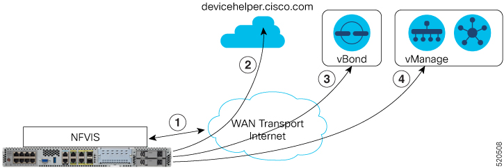
Plug-and-Play Process

The day-zero automated Plug-and-Play (PnP) process provides a simple, secure procedure to discover, install and provision the NFVIS WAN Edge device to join the Cisco Catalyst SD-WAN overlay network.

The steps involved during the PnP onboarding process is as follows:

  1. The NFVIS WAN Edge device on boot up, obtains IP address, default gateway and DNS information through DHCP on the supported device's PnP interface that is connected to the WAN transport (typically Internet).

  2. The NFVIS WAN Edge device attempts to reach the Cisco-hosted PnP connect server. The router attempts to resolve the name of the PnP server at devicehelper.cisco.com and uses an HTTPS connection to gather information about the Cisco SD-WAN Validator, including the organization-name.


    Note


    • For an ENCS deployment using enterprise root-ca certificates, the WAN Edge device receives the root certificates, along with the Cisco SD-WAN Validator and organization-name information from the PnP Connect portal.

    • If an enterprise root-ca certificate is expected as a result of devicehelper.cisco.com, use the show certificate root-ca-cert command to verify that the certificate is received.

    • Starting from Cisco NFVIS Release 4.9.1, establishing a control connection to the management plane via the management port is supported. The management port needs to be connected with Cisco Catalyst SD-WAN for a successful connection to the control plane.


  3. The WAN Edge device authenticates with the Cisco SD-WAN Validator using its chassis or serial number and root certificate. After a successful authentication, the Cisco SD-WAN Validator provides the device with the Cisco SD-WAN Manager.

  4. The WAN Edge device initiates and establishes secure connections with the Cisco SD-WAN Manager and downloads the configuration using NETCONF from Cisco SD-WAN Manager and joins the Cisco Catalyst SD-WAN overlay network.

Staging

NFVIS WAN Edge devices can be staged through the certificate status, controlled from Cisco SD-WAN Manager. Certificates for devices can be placed in staging state before deployment. During staging state, the WAN Edge devices can only establish secure control connections with the Cisco SD-WAN Control Components. The data plane connections are not created.

You can use the WAN Edge devices in the staged state to prepare the device, which may involve upgrading the software and configuring the device, before fully integrating it into the Cisco Catalyst SD-WAN overlay network by changing the certificate status from Staging to Valid from the Cisco SD-WAN Manager GUI.

NFVIS WAN Edge Certificate Status

The NFVIS WAN Edge device certificate in Cisco SD-WAN Manager, can be configured to be in one of the below states:

  • Invalid – In this state, the WAN Edge device is not authorized to join the Cisco SD-WAN Control Components and the overlay network. The device does not form control plane or data plane connections to any of the Cisco Catalyst SD-WAN components.

  • Staging – In this state, the WAN Edge device establishes secure control plane connections to the Cisco SD-WAN Control Components (Cisco SD-WAN Validator, Cisco SD-WAN Manager) only. It is important to note that no data plane connections are established with other WAN Edge devices in the overlay network.

  • Valid – In this state, the WAN Edge device is fully onboarded onto the Cisco Catalyst SD-WAN network. The device establishes secure control plane connections with the controllers and secure data plane connections with all the other WAN Edge routers in the Cisco Catalyst SD-WAN overlay network.

Zero-Trust Model

The NFVIS SD-Branch solution is a Zero-Trust model. Trusting a WAN Edge device includes WAN device whitelist and the root certificate. The device certificate must also be in a Valid state to be authorized on the network.

WAN Edge devices have to be known and authorized by all the Cisco SD-WAN Control Components before allowing the device onto the network. Authorizing the device can be done by:

  • Adding the device in Plug-and-Play connect portal and associating it with the Cisco SD-WAN Validator profile.

  • Synchronizing the device list to Cisco SD-WAN Manager or manually downloading and importing the provisioning file to Cisco SD-WAN Manager.


Note


WAN Edge network devices can be added automatically and associated with the Cisco SD-WAN Validator profile in the Plug-and-Play connect portal by assigning the smart account and virtual account details.


Network Firewall Requirements

To deploy WAN Edge devices behind a firewall, ensure that the appropriate ports are opened for the Cisco SD-WAN Control Components to securely establish connections.

  • By default, all the Cisco SD-WAN Control Components attempt to use DTLS, UDP base port 12346 to establish connections.

  • If the WAN Edge device is unable to establish control connections with the Cisco SD-WAN Control Components using the default base port or if multiple WAN Edge devices are placed behind a NAT device, the WAN Edge device can port hop through 5 base ports. Port hopping is done sequentially on ports 12346, 12366, 12386, 12406, and 12426 before returning to port 12346. Port hopping is enabled by default on the WAN Edge device.

  • A port-offset can be configured to uniquely identify each WAN Edge device placed behind a NAT device and to prevent attempts from using the same base ports. A port offset is a number from 0 to 19, 0 being the default. If a port-offset is configured, the default base port is incremented with the port-offset value and the subsequent ports are incremented by 20. For example, in a deployment with a port-offset value set to 1, then the WAN Edge initiates the connection with port 12347 (12346+1) and then subsequently port hopping is done sequentially on ports 12347, 12367, 12387, 12407, 12427 before returning to port 12347.

  • The WAN Edge device uses the same base ports to establish data plane connections, such as IPsec connections and BFD sessions, with other WAN Edge devices in the overlay network.

  • The Cisco SD-WAN Validator always uses DTLS, UDP source port 12346, to establish control connections with the Cisco SD-WAN Control Components. The default port can be changed with a configuration change.

Network Design

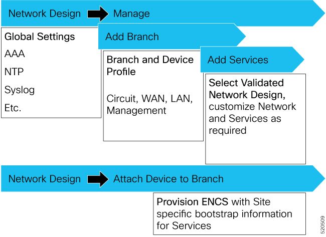
Use the Network Design feature on Cisco SD-WAN Manager to create and manage an overlay network topology. You can add circuits, data centers, and branch sites to a network topology, configure LAN, WAN, and management interfaces for elements in the topology, review the topology, and perform related tasks. The network design operations are particularly useful for small-scale deployments that include data centers and branch sites.

Network design consists of these major workflows:

  • Create network topology—Create circuits, data centers, and branch sites, in this order. A network topology must include at least one circuit and one data center.

  • Configure device profiles—Configure global parameters and options for LAN, WAN, and management settings.

  • Attach devices profiles—Attach device profiles to devices.

  • Ongoing management—Add elements to the network topology and modify the configuration settings for elements as needed.

Configure Network Design Elements

With the network design feature, you can create a new overlay network topology and modify existing elements in a topology. You can perform these activities from the Network Design page on Cisco SD-WAN Manager.

Creating a new network topology involves performing the following procedures in the order shown:

Table 1.

Procedure

Description

Reference

1

Add circuits.

See Configure Circuits .

3

Add branch sites.

See Configure Branch Sites.

4

Configure global parameters.

See Configure Global Parameters.

5

Configure device profiles.

See Configure Device Profiles.

A network topology must include at least one circuit. After a network topology is created, you can modify its elements directly.

Configure Circuits

Each network topology must have at least 1 circuit and can have up to 18 circuits. NFVIS can use only one circuit for establishing control connection. In case of failure of the configured circuit, alternate circuits cannot be used.

To configure circuits for a network topology, follow these steps:

  1. From the Cisco SD-WAN Manager menu, choose Configuration > Network Design.

  2. Choose Create Network Design (which is displayed if you have not yet created a network topology) or Manage Network Design (which is displayed if you have created a network topology).

  3. Choose Circuits.

    A screen for configuring circuits is displayed. If any circuits have been created, this screen lists them. You can remove a circuit by clicking its corresponding delete icon.

  4. Click Add New.

  5. Choose the Private or the Public radio button to indicate whether the circuit is private or public.

  6. From the Circuit Color drop-down list, choose a predefined color to uniquely identify the transport location (TLOC) in a circuit.

    The color you choose cannot be used for a TLOC in any other circuit in the topology.

  7. To add more circuits, repeat steps 2 through 5.

  8. To remove a circuit that you added, click its corresponding Delete icon.

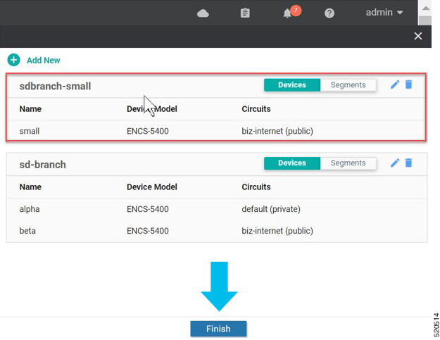
  9. Click Finish.

  10. Click Save on the Network Design screen.

    Or, if you do not want to save the updates that you made, click Cancel.

Configure Branch Sites

Configuring a branch site involves assigning a name and adding device profiles and segments to the branch site. Each network topology must have at least one branch site.

To configure branch sites for a network topology:

  1. Frome the Cisco SD-WAN Manager menu, choose Configuration > Network Design.

  2. Choose Create Network Design (which is displayed if you have not yet created a network topology) or Manage Network Design (which is displayed if you have created a network topology).

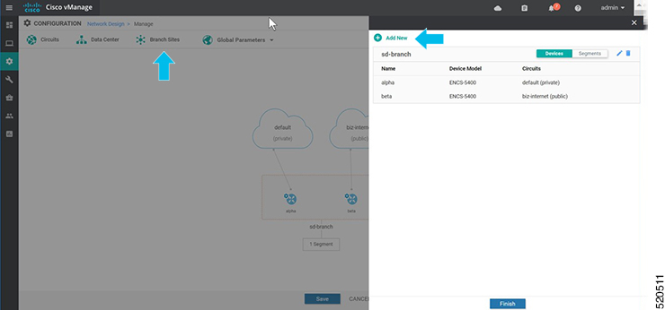
    Click Branch Sites. This option is dimmed out if you have not added at least one circuit.

    Configuring branch sites page appears. If any branch sites have already been created, this page lists them.

    To add a branch site, click Add new.

  3. To add a branch:

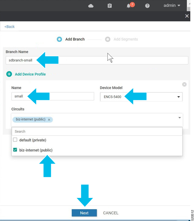
    1. Enter a unique name for the branch site in Branch Name. This name cannot be used for any other data center, branch site, or device profile in the topology. The name can include letters, numbers, underscores, and hyphens, but no spaces or special characters.

    2. To add a new device profile, click Add Device Profile.

      Each branch site must have at least one device profile. A device profile is associated with a specific device type in the branch site and provides configuration settings that are pushed to those device types.

    3. Enter Name to enter a name for the device profile

    4. From the Device Model drop-down list, choose the device type to associate with the device profile.

    5. Choose Circuits to display a list of circuits that you have created and then check the box next to each circuit that the device profile should be associated with.

    6. Click Next.

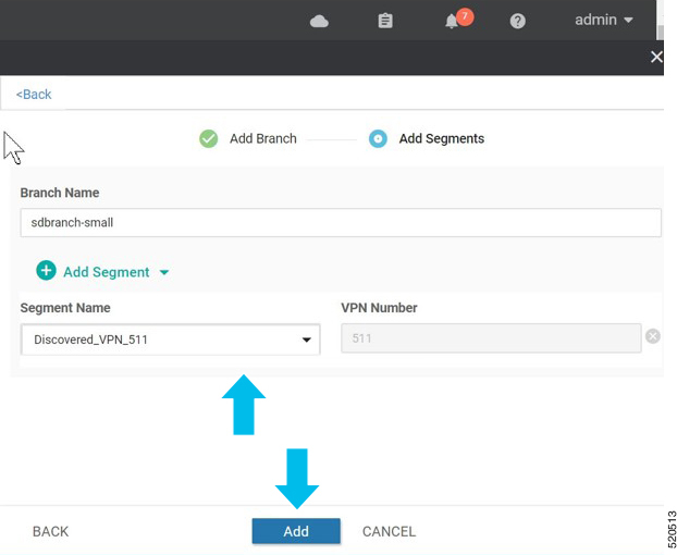
  4. A segment is a service side VPN that is associated with all device profiles in the branch site. Each branch site must have at least one segment. You can use the same segment in multiple branch sites.To add one or more segments:

    1. Click Add Segment. Choose a segment from the drop-down list. The VPN Number populates automatically with the VPN ID that was configured for the segment.

    2. Click Add.

    The system displays a list of branch sites.

  5. Click Finish.

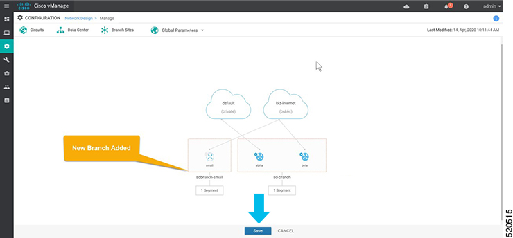
  6. Click Save on the Network Design page.

Configure Global Parameters

Global parameters are configuration settings that are used in all device profiles in a network topology. If you do not configure global parameters, factory default configuration settings are used for device profiles.

SD-Branch currently supports NTP, AAA and logging parameters only.

To configure global parameters:

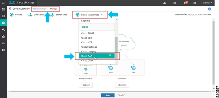
  1. From the Cisco SD-WAN Manager menu, choose Configuration > Network Design.

  2. Choose Create Network Design (which is displayed if you have not yet created a network topology) or Manage Network Design (which is displayed if you have created a network topology).

    Choose Global Parameters and choose the desired template from the drop-down list.

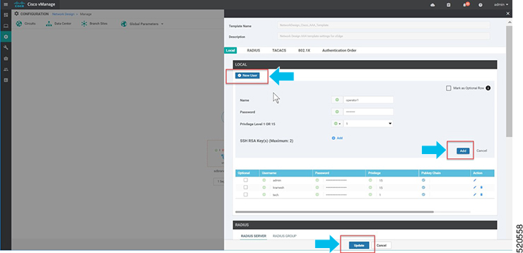
  3. Configure the template.

    The template name and description is automatically populated and cannot be changed. You cannot select a device type as the template is used for all devices throughout your network.

    To add a new user, select + New User, and enter the details. Click Add.

    Click Update to complete the configuration.

    Cisco vManage 20.1 and 20.3 releases support only AAA global parameters on local users. You can update TACACS and RADIUS settings through the Add-on CLI feature configuration on the device.

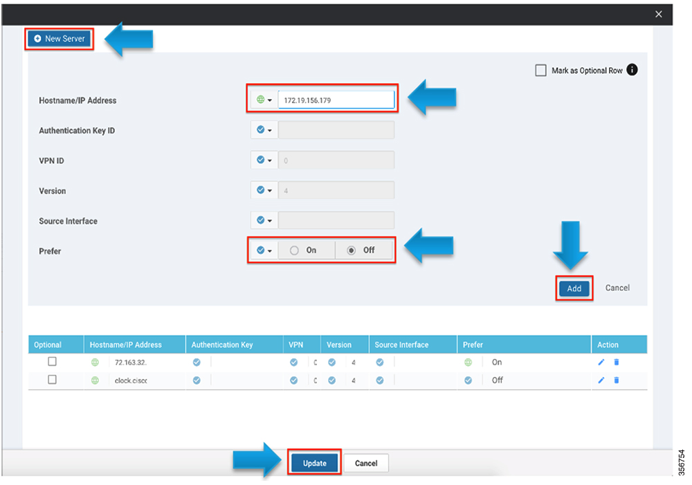
  4. Add NTP server.

    To add a new server, choose + New Server and enter Hostname/IP Address.

  5. Choose Prefer options and click Add.

    Click Update to complete the configuration.

    Authentication Key ID, VLAN ID, Version and Source Interface is not applied to NFVIS platforms. NFVIS platforms supports only one preferred and one backup NTP servers.

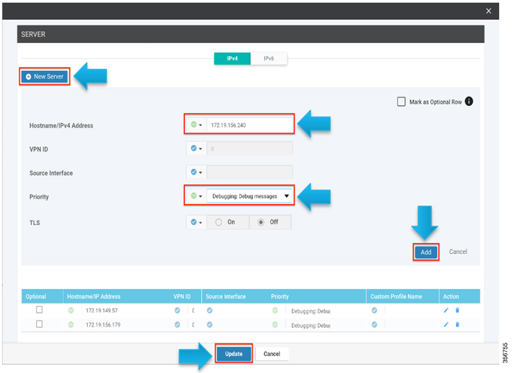
  6. Add logging server.

    To add a new server, select + New Server and enter Hostname/IP Address. Choose Priority options and click Add.

    Click Update to complete the configuration.

    VPN ID and Source Interface is not applied to NFVIS platforms. The maximum number of logging servers supported is four. Ensure that Priority is using the same setting. NFVIS platforms support only one priority or logging severity as a globlal configuration.

Configure Device Profiles

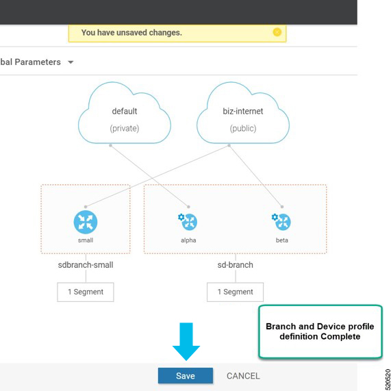
You must configure a device profile for each router in a data center or a branch site before the device profile can be attached to the router.

To configure a device profile for a router in a network topology:

  1. From the Cisco SD-WAN Manager menu, choose Configuration > Network Design.

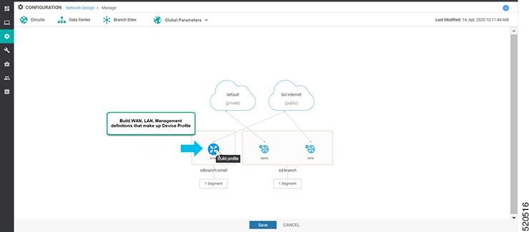
  2. A network diagram is displayed on the Network Design page. When you hover your mouse over the image representation of the device, choose Build profile.

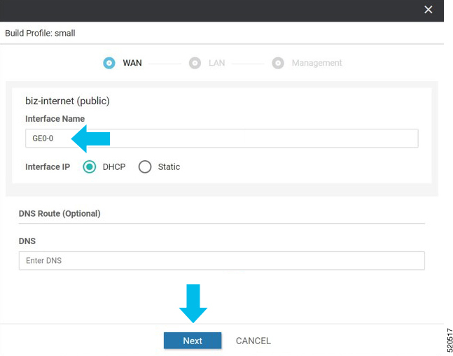
  3. To build a device profile, enter the WAN interface details for the profile:

    • Enter the name of a TLOC interface to associate it with the a circuit that is associated with this router, in Interface Name.

    • Choose one of the radio buttons, DHCP or Static.

    • (Optional) Enter the IP address of the primary DNS server in the network in DNS server.

    • Click Next.

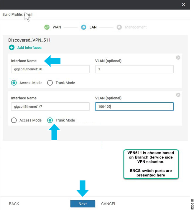
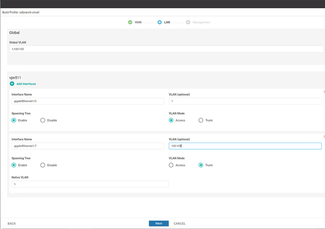
  4. Enter the LAN interface details for the profile:

    • Enter the name of a LAN side interface in Interface Name to associate with the segment .

    • (Optional) Enter a sub-interface in VLAN if needed for your deployment.

    • Choose one of the radio buttons, Access Mode or Trunk Mode.

    • Click Next.

    Global VLANs must be defined using addon CLI template. Global VLANs are a collection of all VLANs used in the ENCS switch ports.

    Starting from NFVIS 4.4 release, you can set some additional LAN interface details from Cisco SD-WAN Manager.

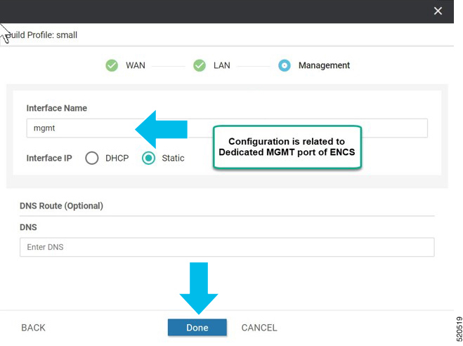
  5. Enter the management interface details for the profile:

    • Enter the name for the management interface in Interface Name to associate with the device.

    • Choose one of the radio buttons, DHCP or Static.

    • Click Done.

  6. Click Save on the Network Design screen.

ENCS Device Profile and Additional Services

For ENCS 5400 device, you have to configure both device profile and addon services. After you configure a device profile, continue with adding services on the ENCS branch design.

VNF image package for services, virtual networks and associated virtual switch or bridge are part of the ENCS network design. Virtual NICs (VNICs) are part of the VNF services and the order of the VNICs must be configured correctly for continuous traffic flow through the different services, in the intended order. To simplify the user experience, there are a set of prescriptive Cisco validated designs that you can choose and complete the network design. You can also customize the network topology if required, to delete and modify, services or networks.

In the following example, Cisco Catalyst SD-WAN router and Cisco NGFW based network topology is created. This procedure can be applied to other Cisco validated network design templates.

To add services and create network topology template for a group of sites:

  1. From the Cisco SD-WAN Manager menu, choose Configuration > Network Design.

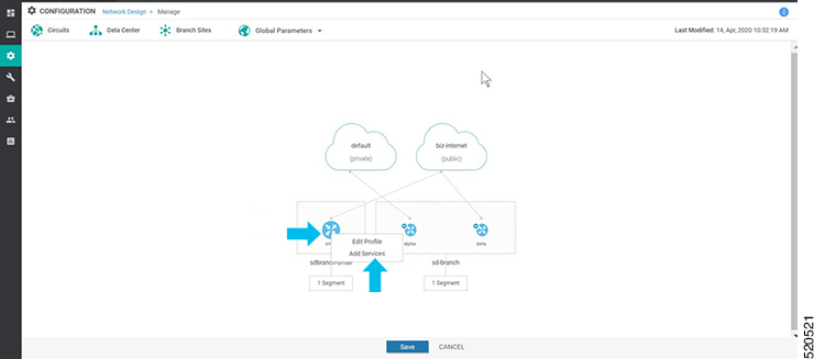
  2. A network diagram is displayed on the Network Design page. Hover your mouse over the image representation of the branch device and choose Add services.

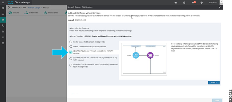
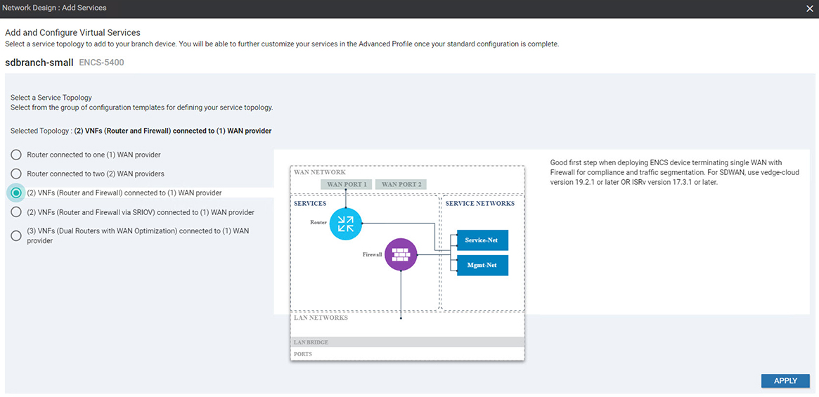
  3. In the Add services page, choose a service topology from the list of available configuration templates. Click Apply.

    Starting from NFVIS 4.4 release, a graphical view of the topology is available for the listed templates.

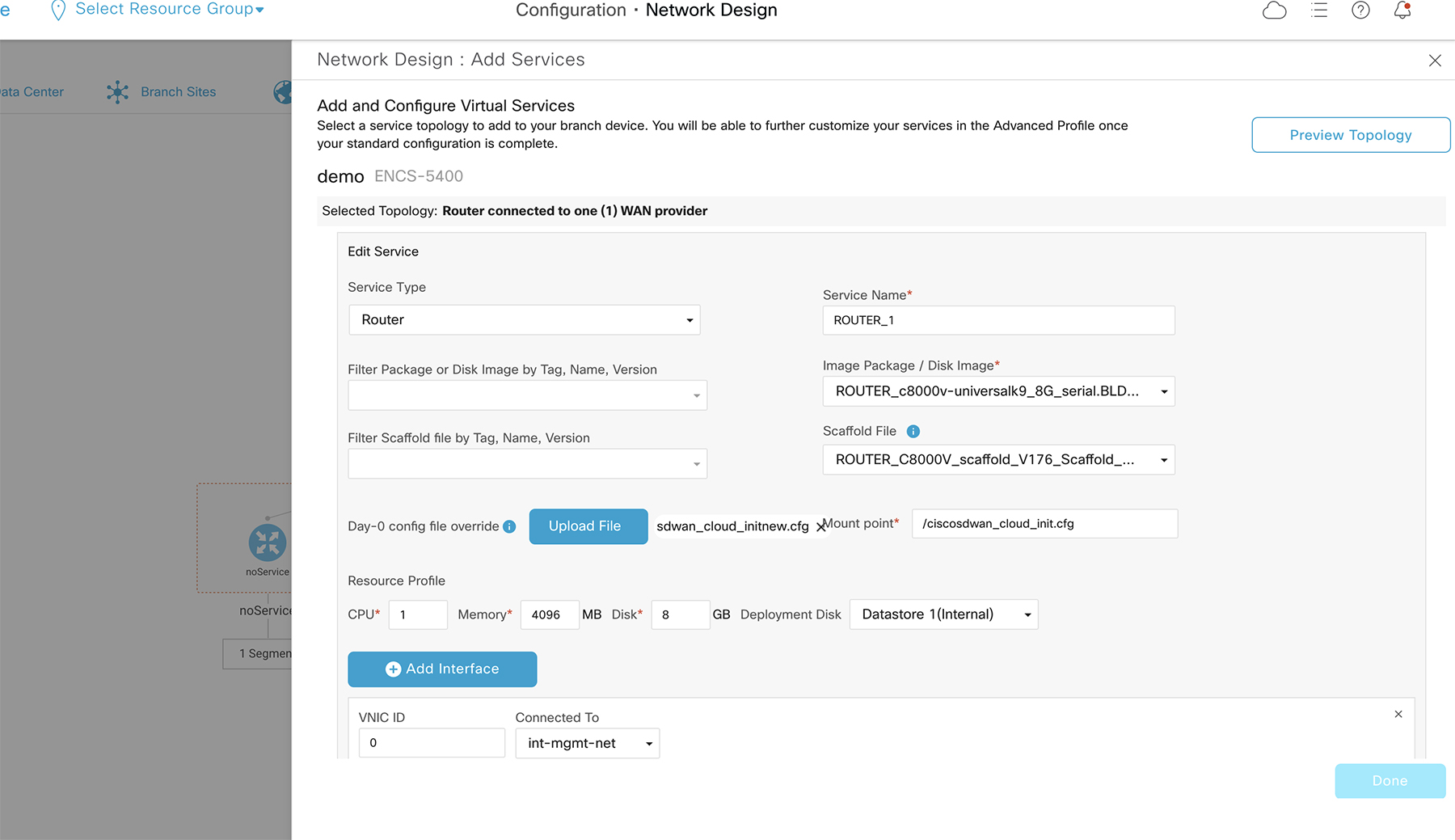
  4. Starting from NFVIS 4.6.1 release, you can upload either a tar.gz file or a qcow2 file when registering your image and you can tag the image with keywords to help identify it. You can also upload a scaffold file.

    (Optional) To upload a Day 0 configuration file, that overrides any settings in the scaffold or tar.gz files or an existing Day 0 configuration in the package or scaffold file, ensure the following:

    • Variables are represented within “{{“ “}}”. Example: {{SAMPLE_VARIABLE}}

    • Passwords are represented within “$${“ and “}”. Example : $${SAMPLE_PASSWORD}

    • Variables to be ignored are represented within “${“ and “}”. Example: ${NICID_0}


    Note


    The mount point value varies with the VNF. The different mount point values are as follows:

    • For C8000v and ISRv in controller/ Cisco SD-WAN Manager mode: ciscosdwan_cloud_init.cfg

    • For C8000v and ISRv in autonomous/non-Cisco SD-WAN Manager mode: iosxe_config.txt

    • For vEdge Cloud: /openstack/latest/user_data

    • For ASAv and FTDv: day0-config


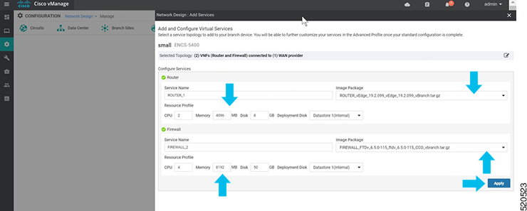
  5. To add and configure the virtual services, enter the details of the virtual services:

    • Choose the Image Package from the drop-down list, and enter details to the resource profiles.


      Note


      When you deploy the device in a remote site, verify if the image is available on your local system to skip the image download over WAN. For more information see, ENCS5400 Deployment in Sites with Low WAN Bandwidth


    • Click Apply.

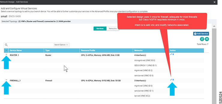
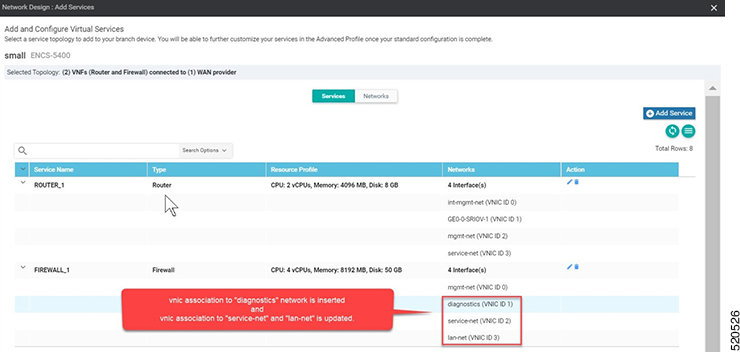
  6. The list of services added in the previous step are displayed on this page. You can add or modify networks associated with each device.

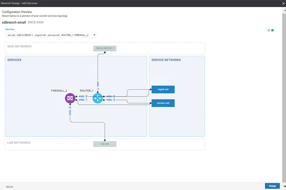
    Starting from NFVIS 4.4, you can click Preview Topology to view the topology of the added services along with the associated networks. You can use the drop down menu to Filter View and view only the services that you want.

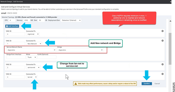
  7. Click + Add Interface to add a new network. Enter the network details associated with the new network.

    Modify the details related to the exisitng interfaces

    Click Confirm.

  8. You can see the new and modified interfaces in the Services page.

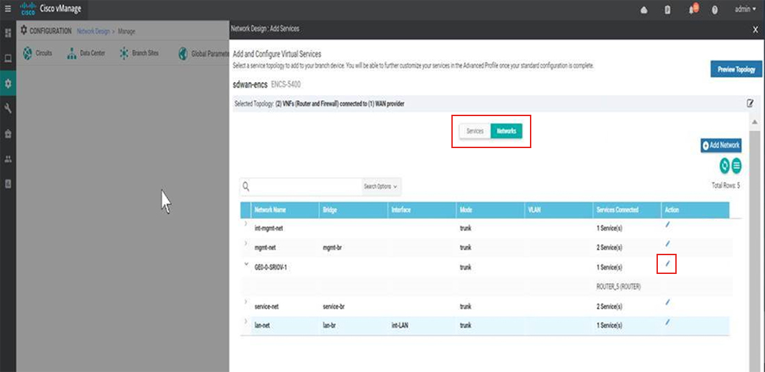
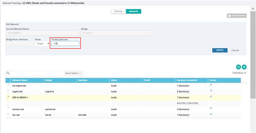
  9. To define VLAN for the SRIOV networks, select Networks. In the list of networks displayed you can add or modify the networks.

  10. For WAN side network, by default all VLANs in trunk mode are allowed. If you have set the Dot1q in ISRv, VLAN passes through the network.


    Note


    There is a known race condition defect that leads to VNF deployment failure when VLANs are configured in networks using NFVIS 4.2.1. You can upgrade to NFVIS 4.4.1 along with Cisco vManage 20.4.1 or above to resolve this issue.


CLI Add-On Feature Templates

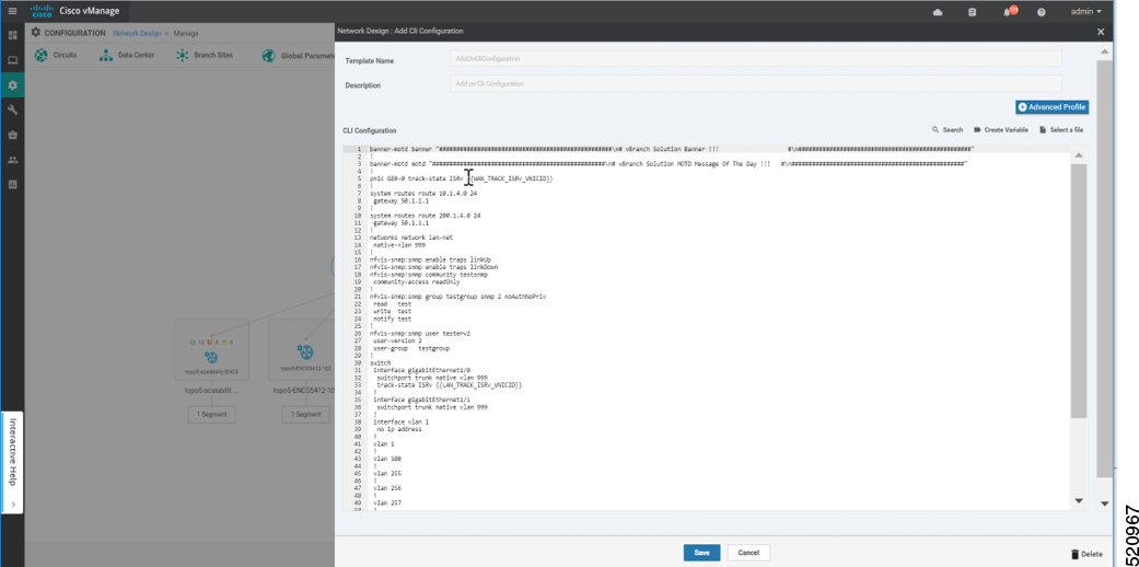
You can use CLI add-on feature templates to attach specific CLI configurations to a device. CLI add-on feature templates must be used in conjunction with Network Design. It is recommended to use this feature only for configurations that are not natively supported in Network Design.

To create a CLI add-on feature template:

  1. From the Cisco SD-WAN Manager menu, choose Configuration > Network Design.

  2. Click Create Network Design (which is displayed if you have not yet created a network topology) or Manage Network Design (which is displayed if you have created a network topology).

    Hover your mouse over the image representation of the branch device and choose Add CLI Configuration.

This section lists the supported add-on CLI configurations for the following features in NFVIS. For more information, see Cisco Enterprise Network Function Virtualization Infrastructure Software Configuration Guide

Boot-up time


vm_lifecycle tenants tenant admin
deployments deployment deployment-ROUTER_1
  vm_group deployment-ROUTER_1
   bootup_time        600

Port tracking


pnic GE0-0 track-state ROUTER_1 1

ACL


system settings ip-receive-acl 0.0.0.0/0
service  [ scpd ]
action   accept
priority 0
!
system settings ip-receive-acl 10.31.40.24/32
service  [ scpd ]
action   accept
priority 5
!

Static route


system routes route 192.168.10.10 24
gateway 192.168.0.2

TACACS+


aaa authentication tacacs
tacacs-server host 172.19.156.179
key                     7
encrypted-shared-secret cisco123
admin-priv              15
oper-priv               14
!

Banner


banner-motd banner "Banner for vBranch"

Message of the Day (MOTD).


banner-motd motd "MOTD for vBranch"

SNMP


nfvis-snmp:snmp enable traps linkUp
nfvis-snmp:snmp enable traps linkDown
nfvis-snmp:snmp community testsnmp
community-access readOnly
!
nfvis-snmp:snmp group snmpgroupv1 snmp 1 noAuthNoPriv
read test
write test
notify test
!
nfvis-snmp:snmp group snmpgroupv2 snmp 2 noAuthNoPriv
read test
write test
notify test
!
nfvis-snmp:snmp group snmpgroupv3 snmp 3 authPriv
read test
write test
notify test
!
nfvis-snmp:snmp user testerv1
user-version 1
user-group snmpgroupv1
!
nfvis-snmp:snmp user testerv2
user-version 2
user-group snmpgroupv2
!
nfvis-snmp:snmp user testerv3
user-version 3
user-group snmpgroupv3
auth-protocol sha passphrase cisco123
priv-protocol aes passphrase cisco123
!
nfvis-snmp:snmp host SNMP-SERVER-57
host-port 161
host-ip-address 172.19.149.57
host-version 3
host-security-level authPriv
host-user-name testerv3
!
nfvis-snmp:snmp host SNMP-SERVER-179
host-port 161
host-ip-address 172.19.156.179
host-version 1
host-security-level noAuthNoPriv
host-user-name testerv1
!
nfvis-snmp:snmp host SNMP-SERVER-229
host-port 161
host-ip-address 172.25.221.229
host-version 2
host-security-level noAuthNoPriv
host-user-name testerv2
!

Default gateway


system settings default-gw 172.25.217.1

Configure VLAN range instead of individual VLAN CLI for ENCS switch. VLAN range value can be parameterized which is useful in configuring site specific VLAN range variations.

Note


This command is supported only for NFVIS 4.4 and newer versions.


switch vlan-range 1,100,200,300-305

ENCS switch configurations: global VLAN, access vlan, trunk vlan, native vlan, spanning tree, port-channel, track-state, speed, duplex and QoS


switch
interface gigabitEthernet1/0
track-state ISRv 3
!
interface gigabitEthernet1/1
speed 100
duplex full
!
interface gigabitEthernet1/2
channel-group 1 mode auto
!
interface gigabitEthernet1/3
channel-group 1 mode auto
!
interface gigabitEthernet1/4
speed 100
switchport mode access
switchport access vlan 100
!
interface gigabitEthernet1/5
spanning-tree disable
!
interface gigabitEthernet1/6
speed 1000
duplex full
switchport mode trunk
switchport trunk native vlan 101
no switchport trunk allowed
switchport trunk allowed vlan vlan-range 8,113-114,130
!
interface gigabitEthernet1/7
qos cos 3
switchport mode trunk
switchport trunk native vlan 999
no switchport trunk allowed
switchport trunk allowed vlan vlan-range 255-257,999
!
interface port-channel1
spanning-tree mst 1 cost 200000000
spanning-tree mst 2 cost 200000000
switchport mode trunk
no switchport trunk allowed
switchport trunk allowed vlan vlan-range 100,126-128

!
vlan 1
!
vlan 8
!
vlan 100
!
vlan 101
!
vlan 113
!
vlan 114
!
vlan 126
!
vlan 127
!
vlan 128
!
vlan 130
!
vlan 255
!
vlan 256
!
vlan 257
!
vlan 996
!
vlan 997
!
vlan 998
!
vlan 999
!
qos port ports-trusted
qos trust cos-dscp
spanning-tree mode mst
spanning-tree mst 2 priority 61440
spanning-tree mst configuration
name mst_LAN
instance 1 vlan 996-998
instance 2 vlan 100,126-128
!
!

Single IP Address Sharing between NFVIS and the Router VM

single-ip-mode vm-name deployment-name-of-ROUTER

Single IP Address Sharing between NFVIS and Router VM

Table 2. Feature History

Feature Name

Release Information

Description

Support for Single IP Address for NFVIS and the Router VM

NFVIS 4.5

Cisco vManage Release 20.5.1 and later

This release extends the support for using a single public IP address between NFVIS and the router VM to the SD-Branch solution.

Overview of Single IP Address Sharing

Typically, in a virtual branch deployment, two public IP addresses are needed for each branch site, one for the NFVIS and the other for the router VM. With the support for sharing a single IP address, a single public IP address that is assigned to a branch site, can be shared between NFVIS and the router VM deployed on NFVIS. This feature limits the number of public IP addresses required to just one, and also ensures that the branch site is reachable even if the router is in failure state.

Use the CLI Add-on feature template in Cisco SD-WAN Manager to configure this feature.

How Single IP Address Sharing Works

  • NFVIS in a branch site has a public IP address assigned. The required single IP address configuration is configured using the Add-on CLI feature template in Cisco SD-WAN Manager.

  • Cisco SD-WAN Manager pushes this configuration to NFVIS. NFVIS then releases its WAN IP address to the router VM that is being deployed.

  • The deployed VM acts as the gateway for NFVIS.

  • NFVIS periodically pings the NFVIS Internet gateway, through the deployed VM, to verify NFVIS-to-Cisco SD-WAN Manager connectivity. If NFVIS is unable to connect to the Internet gateway, it does the following:

    1. Shuts down the router VM deployed on NFVIS

    2. Reclaims the IP address it assigned to the VM

    3. Tries to reestablish the control connection with Cisco SD-WAN Manager

Supported VMs

Single IP address sharing between NFVIS and router VMs is only supported for the following router VMs:

  • Cisco Catalyst 8000V Edge Software (Cisco Catalyst 8000V)

  • Cisco Integrated Services Virtual Router (ISRv)

  • Cisco vEdge Cloud router

Configure Single IP Address Sharing

Step 1: Configure Router VM

The following example shows the SDWAN NAT DIA configuration that must be included on the router VM. In this example, GigabitEthernet1 is the MGMT interface connected through int-mgmt-net on NFVIS. GigabitEthernet2 is the VPN 0 WAN interface connected through GE0-0 on NFVIS.


Note


Ensure that int-mgmt-net subnet mask is consistent across all the Cisco NFVIS devices. When you deploy a single IP topology and provide different int-mgmt-net subnet masks, the Cisco NFVIS devices loses the control connection.


Interface Gigabitethernet1 
ip nat inside
Interface Gigabitethernet2  
ip nat outside
 
ip nat inside source list NAT interface GigabitEthernet2 overload
ip access-list standard NAT permit ip 10.20.0.0 0.0.0.255
vrf definition 500
!
address-family ipv4
exit-address-family
!
address-family ipv6
exit-address-family
!

interface Gigabitethernet1 
 vrf forwarding 500

interface Gigabitethernet2  
 ip nat outside
 
ip nat route vrf 500 0.0.0.0 0.0.0.0 global
ip nat inside source list nat-dia-vpn-hop-access-list interface GigabitEthernet2 overload
!

Note


VRF 500 is an example and can be changed to any allowed SDWAN VPN number (range: 0 to 65527) other than 0 and 512.


Note


For end-to-end configuration example, see Appendix.


Step 2: Configure Single IP Address Sharing

The following is the sample configuration that must be included in the CLI Add-on feature template to enable single IP address sharing between NFVIS and the router VM. In this example, deployment-ROUTER_1.deployment-ROUTER_1 is the deployment name of the router VM.


single-ip-mode vm-name deployment-ROUTER_1.deployment-ROUTER_1

Note


For end-to-end configuration example, see the Appendix chapter.


Verify Single IP Address Sharing

The following is sample output from the show single-ip-mode command, which is used to verify the status of single IP mode..

Device# show single-ip-mode
single-ip-mode state active
single-ip-mode state-details "VM alive"

The following is sample output from the show control connections command, which is used to verify Cisco NFVIS to Cisco SD-WAN Manager control connection.

Device# show control connections                                                                                       PEER                                          PEER
                 CONTROLLER
PEER    PEER PEER            SITE       DOMAIN PEER                                    PRIV  PEER                                    PUB
                 GROUP
TYPE    PROT SYSTEM IP       ID         ID     PRIVATE IP        PORT  PUBLIC IP      PORT  LOCAL COLOR     PROXY STATE UPTIME      ID
----------------------------------------------------------------------------------------------------------------------------------------------------------------------------------------
vmanage dtls 10.10.10.29     101        0      172.19.156.234    12846 172.19.156.234 12846       bronze    No    up     0:01:41:22  0