Secure Overlay
An overlay is a virtualized network layer on top of the physical network with the support of its infrastructure to provide additional security to the network. IPSec is a framework with protocols and algorithms to provide secured data transmission over unprotected or untrusted networks. IPSec secure tunnel is created between two networks to ensure virtual private network communication.
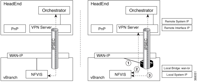
Secure overlay in NFVIS allows IPSec tunnel establishment between NFVIS supporting the vBranch platform and a VPN server and allows the orchestrator to manage NFVIS over the IPSec tunnel.
Supported Features on Secure Overlay
The following features are supported on NFVIS 3.10.x and later releases:
-
IPSec IKEv2
-
IPv4
-
Authentication:
-
Pre-shared-key authentication
-
Introduced in NFVIS 3.12.3 release - EAP authentication
-
-
IKE cipher:
-
aes128-sha1-mopd1536
-
Introduced in NFVIS 3.12.3 release - aes256-sha512-modp2048
-
Introduced in NFVIS 3.12.3 release - aes256-sha512-modp4096
-
-
ESP cipher:
-
aes128-sha1
-
Introduced in NFVIS 3.12.3 release - aes256-sha512
-
Introduced in NFVIS 4.2.1 release - aes256-sha512-modp2048
-
Introduced in NFVIS 4.2.1 release - aes256-sha512-modp4096
-
Introduced in NFVIS 4.4.1 release - aes128-sha1-modp1536, aes256-sha1-modp2048, and aes256-sha256-modp2048
-
-
Local system IP address:
-
Unique tunnel IP address for each NFVIS system.
-
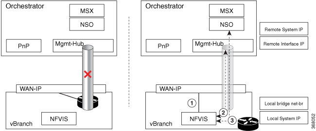
Introduced in NFVIS 3.11.1 release - Internal management network bridge (int-mgmt-net-br) gateway IP address is allowed to be used as local system IP address. In this case, the local system IP bridge much be set to internal management network (int-mgmt-net).
-
Introduced in NFVIS 4.4.1 release - local system IP address can be learnt through IPSec negotiation when local system IP address is not configured.
-
-
Local system IP subnet:
-
local system IP subnet prefix.
-
Introduced in NFVIS 4.4.1 release - local system IP address and subnet can be learnt through IPSec negotiation. In this case local system IP subnet should not be configured.
-
-
Local bridge for NFVIS reaching out to remote VPN server:
-
wan-br by default
-
wan2-br
-
-
Local bridge and Dual local bridge:
Introduced in NFVIS 3.12.1 release - Secure overlay is support on NFVIS Dual WAN feature. DHCP client toggles between wan and wan2 to request for an IP address. When IP address and default gateway are obtained from an interface with DHCP configuration, the toggling stops. If dual-local-bridge is configured, to start overlay, NFVIS selects the interface between local-bridge and dual-local-bridge, in the following order:
-
Interface with DHCP configuration.
-
Interface having static IP address.
-
If both interfaces have static IP address, local-bridge interface.
-
-
Local identity:
-
IP address or FQDN
-
Introduced in NFVIS 3.12.3 release - email domain
-
-
Remote identity:
-
IP address or FQDN
-
Introduced in NFVIS 3.12.3 release - Distinguish Name
-
Introduced in NFVIS 3.12.3 release - email domain
-
Introduced in NFVIS 4.4.1 release - Active-Standby headend VPN responder scenario is supported. You can configure a list of Remote IDs, each of which is corresponding to one remote VPN responder.
-
Introduced in NFVIS 4.5.1 release - Remote ID configuration using EAP authentication is simplified. If the added security using a distinguished name is not required when using EAP authentication, then an FQDN can be configured on NFVIS to simplify the remote ID configuration and reduce authentication complexity.
-
-
Remote Interface IP address:
-
IP address
-
Introduced in NFVIS 4.4.1 release - FQDN
-
For the FQDN, DNS server has to be configured in system settings or learned through DHCP.
-
-
Remote system IP address:
-
IP address
-
Introduced in NFVIS 4.4.1 release - Active-Standby headend VPN responder scenarios is supported. You can configure a list of Remote system IP addresses, each of which is corresponding to a tunnel IP address on a remote VPN responder.
-
Introduced in NFVIS 4.5.1 release - Remote system IP address can be learned from the remote VPN responder. To do so, leave the remote-system-ip-addr field out the of secure overlay configuration entirely
-
-
Remote system IP Subnet:
-
User can specify IP subnet prefix.
-
Introduced in NFVIS 4.1.1 release - User can specify 0.0.0.0/0.
-
Default route is set to Secure Overlay tunnel
-
Following routes bypass the tunnel:
-
If PNP server IP address is discovered before Secure Overlay is configured
-
If DNS server IP address is set before Secure Overlay is configured.
-
Any NFVIS local static route
-
Any route added by user using system routes route command
-
-
-
Introduced in NFVIS 4.4.1 release - Active-Standby headend VPN responder scenario is supported. You can configure a list of Remote system IP subnets, each of which corresponds to a tunnel IP address on a remote VPN responder.
-
-
BGP Neighbor Name:
-
Introduced in NFVIS 4.4.1 release, Secure Overlay feature can work together with BGP feature. BGP session can be established over IPSec tunnel. NFVIS can learn private remote subnets from BGP neighbor over the tunnel. These learnt private subnets are added to the routing table for IPsec tunnel. BGP Neighbor Name allows BGP neighbor session to be established with the active secure overlay remote system IP address if the neighbor name is also configured under router bgp configuration. NFVIS will automatically determine which remote system IP address belongs to the active remote IPSec VPN responder.
-
Introduced in NFVIS 4.5.1 release - Secure overlay feature works together with BGP feature to announce NFVIS subnet routes over an IPSec tunnel to a BGP neighbor.
-
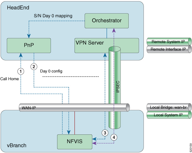
Example for Secure Overlay with Zero Touch Deployment

-
NFVIS has WAN IP address, static IP address or DHCP IP address. NFVIS calls home PnP server.
-
The PnP server pushes NFVIS Day-0 configurations including the secure overlay configuration.
-
NFVIS establishes IPSec connection between NFVIS and the headend management hub which has IPSec VPN configurations. On NFVIS side, the tunnel end point has NFVIS local system IP address.
-
After the IPSec tunnel is up, the headend can connect to NFVIS through the system IP address and manage NFVIS over the IPSec tunnel.
To configure secure overlay:
configure terminal
secure-overlay myconn
    local-system-ip-addr 27.27.27.1
    local-system-ip-bridge int-mgmt-net
    local-id mail@gmail.com
    remote-interface-ip-addr nfvisoverlay.cisco.com
    remote-system-ip-addr [ 166.34.121.111 166.34.121.112 ]
    psk local-psk Cisco1234Admin
    psk remote-psk Cisco1234Admin
     !
confirgure terminal
secure-overlay myconn
local-system-ip-addr 28.28.28.1
local-system-ip-subnet 28.28.28.0/24
local-system-ip-bridge int-mgmt-net
local-id AxxxY@cisco.com
remote-interface-ip-addr C*****d.cisco.com
remote-system-ip-addr [ 166.35.121.112 166.34.121.112 ]
remote-system-ip-subnet [ 166.35.121.112/32 166.34.121.112/32 ]
remote-id [ CN=vbranch,unstructuredAddress=10.30.1.114,unstructuredName=csr-vpn-srvr-02.cisco.com CN=vbranch,unstructuredAddress=10.30.1.153,unstructuredName=csr-vpn-srvr-03.cisco.com ]
ike-cipher [ aes256-sha512-modp2048 ]
esp-cipher [ aes256-sha512-modp2048 ]
eap username admin
eap password  Cisco123#
eap cacert intdatastore:uploads/ca.pem
!
To get the secure overlay state:
nfvis# show secure-overlay
                                          ACTIVE      ACTIVE
               ACTIVE           SELECTED  LOCAL       REMOTE       ACTIVE REMOTE
               LOCAL   STATE    LOCAL     SYSTEM IP   INTERFACE    SYSTEM IP       ACTIVE REMOTE
NAME    STATE  BRIDGE  DETAILS  BRIDGE    ADDR        IP ADDR      ADDR            SYSTEM IP SUBNET   ACTIVE REMOTE ID
-----------------------------------------------------------------------------------------------------------------------------------------------------------------------------------------------
myconn  up     wan-br  -        wan-br    28.28.28.1  10.30.1.153  166.34.121.112  166.34.121.112/32  "CN=vbranch,unstructuredAddress=10.30.1.153,unstructuredName=csr-vpn-srvr-03.cisco.com"

nfvis#
Examples for Configuring Secure Overlay
 Note |
Secure overlay configuration on NFVIS must match with VPN configuration on the VPN server. The secure overlay tunnel will not be established successfully if the configurations do not match. |
Secure Overlay over WAN with pre-shared-key and FQDN remote-id
<config xmlns="http://tail-f.com/ns/config/1.0">
  <secure-overlays xmlns="http://www.cisco.com/nfvis/secure-overlay">
    <secure-overlay>
      <name>myconn</name>
      <local-system-ip-addr>28.28.28.1</local-system-ip-addr>
      <local-system-ip-subnet>28.28.28.0/24</local-system-ip-subnet>
      <local-system-ip-bridge>int-mgmt-net</local-system-ip-bridge>
      <local-id>branch1@vpntest.com</local-id>
      <remote-interface-ip-addr>csrhead.cisco.com</remote-interface-ip-addr>
      <remote-system-ip-addr>166.35.121.112</remote-system-ip-addr>
      <remote-system-ip-addr>166.34.121.112</remote-system-ip-addr>
      <remote-system-ip-subnet>166.35.121.112/32</remote-system-ip-subnet>
      <remote-system-ip-subnet>166.34.121.112/32</remote-system-ip-subnet>
      <remote-id>CN=vbranch,unstructuredAddress=10.30.1.114,unstructuredName=csr-vpn-srvr-02.cisco.com</remote-id>
      <remote-id>CN=vbranch,unstructuredAddress=10.30.1.153,unstructuredName=csr-vpn-srvr-03.cisco.com</remote-id>
      <ike-cipher>aes256-sha512-modp2048</ike-cipher>
      <esp-cipher>aes256-sha512-modp2048</esp-cipher>
      <eap>
        <username>admin</username>
        <password>$7$ZEh54XQvvwwTicwX+lEuMWjuA7q+sfaa</password>
        <cacert>intdatastore:uploads/ca.pem</cacert>
      </eap>
    </secure-overlay>
  </secure-overlays>
</config>
VPN configuration on VPN server:
aaa new-model

!

aaa group server radius radius-group

 server-private 10.30.1.234 auth-port 1812 acct-port 1813 key Cisco123#

 ip vrf forwarding public-vrf

 ip radius source-interface GigabitEthernet2

!

aaa authentication login default group radius-group local

aaa authentication login ucpe-authen group radius-group

aaa authorization console

aaa authorization exec default local

aaa authorization network default local

!

aaa session-id common

!

crypto pki trustpoint TP-self-signed-2641177237
 enrollment selfsigned
 subject-name cn=IOS-Self-Signed-Certificate-2641177237
 revocation-check none
 rsakeypair TP-self-signed-2641177237
crypto pki trustpoint SLA-TrustPoint
 revocation-check crl
crypto pki trustpoint router
 enrollment url http://10.30.1.153:80
 ip-address 10.30.1.114
 subject-name CN=vbranch
 vrf public-vrf
 revocation-check crl
 rsakeypair router
 auto-enroll regenerate
 hash sha512

crypto ikev2 authorization policy uCPE-author-pol
 pool uCPE-pool1
 dns 166.37.162.103 166.37.218.90
 pfs
 route set interface Loopback1001
no crypto ikev2 authorization policy default


crypto ikev2 proposal uCPE-proposal
 encryption aes-cbc-256
 integrity sha512
 group 16 14
no crypto ikev2 policy default


crypto ikev2 policy uCPE-policy
 match fvrf public-vrf
 proposal uCPE-proposal


crypto ikev2 profile uCPE-profile
 description uCPE profile
 match fvrf public-vrf
 match identity remote email domain vpntest.com
 identity local dn
 authentication local rsa-sig
 authentication remote eap query-identity
 pki trustpoint router
 dpd 60 2 on-demand
 aaa authentication eap ucpe-authen
 aaa authorization group eap list default uCPE-author-pol
 virtual-template 1 mode auto


crypto ipsec transform-set tset_aes_256_sha512 esp-aes 256 esp-sha512-hmac
 mode tunnel
crypto ipsec df-bit clear
no crypto ipsec profile default
crypto ipsec profile uCPE-ips-prof
 set security-association lifetime seconds 28800
 set security-association idle-time 1800
 set transform-set tset_aes_256_sha512
 set pfs group14
 set ikev2-profile uCPE-profile
crypto call admission limit ike in-negotiation-sa 30


ip radius source-interface GigabitEthernet2

 route set interface Loopback1001

interface Loopback1

 ip vrf forwarding private-vrf

 ip address 90.90.90.1 255.255.255.255

interface Loopback2

 ip vrf forwarding private-vrf

 ip address 91.91.91.1 255.255.255.0

interface Loopback3

 ip vrf forwarding private-vrf

 ip address 90.90.90.201 255.255.255.128

interface Loopback1001

 description MNSO Interface and Tunnel Loopback

 ip vrf forwarding private-vrf

 ip address 166.35.121.112 255.255.255.255

interface GigabitEthernet1

 ip vrf forwarding private-vrf

 ip address 92.92.92.1 255.255.255.0

 negotiation auto

 no mop enabled

 no mop sysid

interface GigabitEthernet2

 ip vrf forwarding public-vrf

 ip address 10.30.1.114 255.255.255.0

 negotiation auto

 no mop enabled

 no mop sysid

interface GigabitEthernet3

 ip vrf forwarding private-vrf

 ip address 91.91.91.1 255.255.255.0

 shutdown

 negotiation auto

 no mop enabled

 no mop sysid

interface Virtual-Template1 type tunnel

 ip vrf forwarding private-vrf

 ip unnumbered Loopback1001

 ip mtu 1400

 ip tcp adjust-mss 1380

 tunnel vrf public-vrf

 tunnel protection ipsec profile uCPE-ips-prof

ip radius source-interface GigabitEthernet2
Internal management network bridge IP address as local system IP address
 Note |
NFVIS internal management network has gateway IP address 12.12.12.1. |
<secure-overlay>
   <name>mgmthub</name>
   <local-bridge>wan-br</local-bridge>
   <local-system-ip-addr>12.12.12.1</local-system-ip-addr>
   <local-system-ip-bridge>int-mgmt-net</local-system-ip-bridge>
   <remote-interface-ip-addr>10.85.189.36</remote-interface-ip-addr>
   <remote-system-ip-addr>10.19.18.251</remote-system-ip-addr>
   <remote-id>mgmt-hub.cloudvpn.com</remote-id>
   <psk>
      <local-psk>Cisco1234Admin</local-psk>
      <remote-psk>Cisco1234Admin</remote-psk>
   </psk>
</secure-overlay>
dual-local-bridge and int-mgmt-net-br IP as local system IP
<secure-overlay>
   <name>mgmthub</name>
   <local-bridge>wan-br</local-bridge>
   <dual-local-bridge>wan2-br</dual-local-bridge.
   <local-system-ip-addr>12.12.12.1</local-system-ip-addr>
   <local-system-ip-bridge>int-mgmt-net</local-system-ip-bridge>
   <remote-interface-ip-addr>10.85.189.36</remote-interface-ip-addr>
   <remote-system-ip-addr>10.19.18.251</remote-system-ip-addr>
   <remote-id>mgmt-hub.cloudvpn.com</remote-id>
   <psk>
      <local-psk>Cisco1234Admin</local-psk>
      <remote-psk>Cisco1234Admin</remote-psk>
   </psk>
</secure-overlay>
EAP authentication
<secure-overlay>
   <name>mgmthub</name>
   <local-bridge>wan-br</local-bridge>
   <local-system-ip-addr>12.12.12.1</local-system-ip-addr>
   <local-system-ip-bridge>int-mgmt-net</local-system-ip-bridge>
   <local-id>branch101@cisco.com</local-id>
   <remote-interface-ip-addr> 172.19.160.75</remote-interface-ip-addr>
   <remote-system-ip-addr> 192.168.1.90</remote-system-ip-addr>
   <remote-id>CN=vbranch, unstructuredAddress=172.19.160.75, unstructuredName=Headend.headendvpn</remote-id>
   <ike-cipher>aes256-sha512-modp2048</ike-cipher>
   <esp-cipher>aes256-sha51</esp-cipher>
   <eap>
      <username>admin</username>
      <password>Cisco123#</password>
      <cacert>https://cert/csr.pem</cacert>
   </eap>
</secure-overlay>
The following is an example of the VPN configuration on VPN server:
aaa group server radius radius-group
 server-private 172.19.160.190 auth-port 1812 acct-port 1813 key Cisco123#
 ip radius source-interface GigabitEthernet

aaa authentication login default group radius-group
aaa authentication login ucpe-authen group radius-group

ip domain name headendvpn

crypto pki server ca-server
 database level names
 no database archive
 hash sha512
 lifetime certificate 3650
 lifetime ca-certificate 7305 23 59
 auto-rollover 365
 eku server-auth client-auth
 database url flash:ca

crypto pki trustpoint ca-server
 revocation-check crl
 rsakeypair ca-server

crypto pki trustpoint router
 enrollment url http://172.19.160.75:80
 ip-address 172.19.160.75
 subject-name CN=vbranch
 revocation-check crl
 rsakeypair router
 auto-enroll regenerate
 hash sha512

crypto ikev2 authorization policy uCPE-athor-pol
 pfs
 route set interface

no crypto ikev2 authorization policy default

crypto ikev2 proposal uCPE-proposal
 encryption aes-cbc-256
 integrity sha512
 group 16 14

no crypto ikev2 policy default

crypto ikev2 policy uCPE-policy
 match address local 172.19.160.75
 proposal uCPE-proposal
crypto ikev2 profile uCPE-profile
 description uCPE profile
 match identity remote email domain cisco.com
 identity local dn
 authentication local rsa-sig
 authentication remote eap query-identity
 pki trustpoint router
 dpd 60 2 on-demand
 aaa authentication eap ucpe-authen
 aaa authorization group eap list default uCPE-athor-pol
 virtual-template 1 mode auto

crypto ipsec transform-set tset_aes_256_sha512 esp-aes 256 esp-sha512-hmac
 mode tunnel

crypto ipsec profile uCPE-ips-prof
 set security-association lifetime seconds 28800
 set security-association idle-time 1800
 set transform-set tset_aes_256_sha512
 set pfs group16
 set ikev2-profile uCPE-profile

interface Loopback1
 ip address 192.168.254.1 255.255.255.0

interface GigabitEthernet1
 ip address 172.19.160.75 255.255.255.0
 negotiation auto
 no mop enabled
 no mop sysid

interface GigabitEthernet2
 ip address 192.168.1.90 255.255.255.0
 negotiation auto
 no mop enabled
 no mop sysid

interface Virtual-Template1 type tunnel
 description uCPE virt template
 ip unnumbered Loopback1
 ip mtu 1400
 ip tcp adjust-mss 1360
 tunnel source GigabitEthernet1
 tunnel mode ipsec ipv4
 tunnel protection ipsec profile uCPE-ips-prof


 Feedback