Configuring Ethernet CFM for Cisco QFP-Based Platforms

IEEE Connectivity Fault Management (CFM) is an end-to-end per-service Ethernet layer Operations, Administration, and Maintenance (OAM) protocol. CFM includes proactive connectivity monitoring, fault verification, and fault isolation for large Ethernet metropolitan-area networks (MANs) and WANs.

This document describes the implementation of IEEE 802.1ag Standard-Compliant CFM (IEEE CFM) and Y.1731 in Cisco IOS XE software for Cisco QFP-based platforms. Y.1731 is an ITU-T recommendation for OAM functions in Ethernet-based networks. IEEE CFM and Y.1731 together will be called “Ethernet CFM” throughout this document.

Cisco QFP-based platforms inlcude ASR 1000 series routers, ISR 1000 series routers, ISR 4000 series routers, and C8000v series virtual routers.

Prerequisites for Configuring Ethernet CFM for Cisco QFP-Based Platforms

  • The network topology and network administration have been evaluated.

  • Business and service policies have been established.

  • EVC associated with CFM domain must be configured with the L2VFI interface command

    • Before configuring CFM over L2VFI ensure EVC and Bridge Domain are configured.

    • Bridge-domain under L2VFI must be configured prior to configuring CFM MEP

Restrictions for Configuring Ethernet CFM for Cisco QFP-Based Platforms

  • Ethernet CFM on Cisco QFP-based platforms is not compatible with prestandard CFM.

  • Locked Signal (ETH-LCK) and Test Signal (ETH-Test) are not supported.

  • Link Trace (ETH-LTM/ETH-LTR) over L2VFI is not supported.

  • Initiating ETH-DMM/ETH-SLM test on MEP of EVC/EVC+VLAN MA is supported.

  • Initiating ETH-DMM/ETH-SLM test on MEP of port MA is not supported.

  • Configuring MIP/MEP under L2VFI is not supported.

  • For Connectivity Performance Management functionalities, only single-ended delay (ETH-DM) is supported.

  • QinQ encapsulation is not supported on Cisco QFP-based platforms for CFM for routed subinterfaces.

  • EVPN EFI does not support association into EVC. In an EVPN scenario, it only supports configuring down MEP on the EFP. Up MEP cannot send CFM packet out from the EFI to the peer site.

  • Cisco private CFM protocol is not supported. IEEE standard CFM protocol is supported.

Information About Configuring Ethernet CFM for Cisco QFP-Based Platforms

Ethernet CFM

IEEE CFM is an end-to-end per-service Ethernet layer OAM protocol that includes proactive connectivity monitoring, fault verification, and fault isolation. End to end can be provider edge to provider edge (PE to PE) or customer edge to customer edge (CE to CE).

Ethernet CFM is distinct from other metro-Ethernet OAM protocols by being an end-to-end technology. For example, Multiprotocol Label Switching (MPLS), ATM, and SONET OAM help in debugging Ethernet wires but are not always end to end. 802.3ah OAM is a single-hop and per-physical-wire protocol. It is not end to end or service aware. Ethernet Local Management Interface (E-LMI) is confined between the user-end provider edge (uPE) and CE and relies on CFM for reporting status of the metro-Ethernet network to the CE.

The benefits of Ethernet CFM are:
  • End-to-end service-level OAM technology

  • Reduced operating expense for service provider Ethernet networks

  • Competitive advantage for service providers

Benefits of Ethernet CFM

  • End-to-end service-level OAM technology

  • Reduced operating expense for service provider Ethernet networks

  • Competitive advantage for service providers

Maintenance Associations

An MA identifies a service that can be uniquely identified within a maintenance domain. There can be many MAs within a domain. The MA direction is specified when the MA is configured. The short MA name must be configured on a domain before MEPs can be configured.

The CFM protocol runs for a specific MA.

Maintenance Domains

A maintenance domain is a management space for the purpose of managing and administering a network. A domain is owned and operated by a single entity and defined by the set of ports internal to it and at its boundary. The figure below illustrates a typical maintenance domain.

Figure 1. A Typical Maintenance Domain

A unique maintenance level in the range of 0 to 7 is assigned to each domain by a network administrator. Levels and domain names are useful for defining the hierarchical relationship among domains. The hierarchical relationship of domains parallels that of customer, service provider, and operator. The larger the domain, the higher the level value. For example, a customer domain would be larger than an operator domain. The customer domain may have a maintenance level of 7 and the operator domain may have a maintenance level of 0. Typically, operators would have the smallest domains and customers the largest domains, with service provider domains between them in size. All levels of the hierarchy must operate together.

Domains should not intersect because intersecting would mean management by more than one entity, which is not allowed. Domains may nest or touch but when two domains nest, the outer domain must have a higher maintenance level than the domain nested within it. Nesting maintenance domains is useful in the business model where a service provider contracts with one or more operators to provide Ethernet service to a customer. Each operator would have its own maintenance domain and the service provider would define its domain--a superset of the operator domains. Furthermore, the customer has its own end-to-end domain, which is in turn a superset of the service provider domain. Maintenance levels of various nesting domains should be communicated among the administering organizations. For example, one management approach would be to have the service provider assign maintenance levels to operators.

Ethernet CFM exchanges messages and performs operations on a per-domain basis. For example, running CFM at the operator level does not allow discovery of the network by the higher provider and customer levels.

Network designers determine domain configurations.

The following characteristics of domains are supported:

  • Name is a maximum of 154 characters in length.

  • Direction is specified when the MA is configured.

  • Down (toward the wire) MEPs.

A domain can be removed when all maintenance points within the domain have been removed and all remote MEP entries in the continuity check database (CCDB) for the domain have been purged.

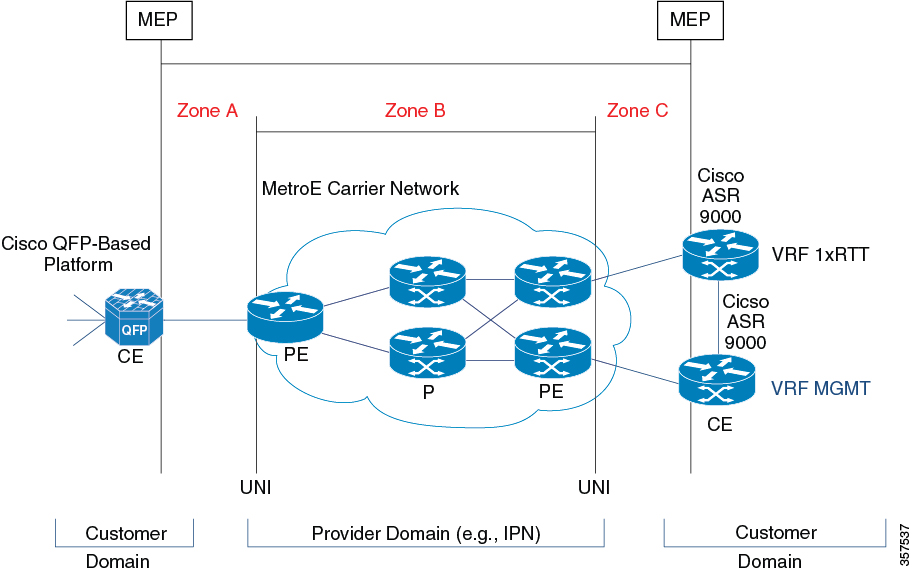
The figure below illustrates service provider and customer domains and where the Cisco QFP-based platform is in the network.

Figure 2. Service Provider and Customer Domains

Maintenance Points

A maintenance point (MIP) is a demarcation point on an interface or port that participates in Connectivity Fault Management (CFM) within a maintenance domain. Maintenance points on device ports act as filters that confine CFM frames within the bounds of a domain by dropping frames that do not belong to the correct level. Maintenance points must be explicitly configured on Cisco devices. Two classes of maintenance points exist, maintenance end points (MEPs) and MIPs. Support for MIPs varies by Cisco release.

Maintenance Association Endpoints

Maintenance association endpoints (MEPs) reside at the edge of a maintenance domain and confine Ethernet Connectivity Fault Management (CFM) messages within the domain via the maintenance domain level. MEPs periodically transmit and receive continuity check messages (CCMs) from other MEPs within the domain. At the request of an administrator, linktrace and loopback messages can also be transmitted. MEPs are either “Up” (toward the bridge) or “Down” (toward the wire). Support for Up MEPs varies by Cisco release.

When the continuity-check static rmep command is configured on a port MEP and continuity checking does not detect a removed MEP, the port is set to MAC operation down and the interface protocol is set to down. Normal traffic is stopped because the line protocol is down, but CFM packets still pass.

MEP configurations can be removed after all pending loopback and traceroute replies are removed and the service on the interface is set to transparent mode.

Down MEPs for Routed Ports

Down MEPs communicate through the wire.

Down MEPs use the port MAC address.

A Down MEP performs the following functions:

  • Sends and receives Ethernet CFM frames at its level via the wire connected to the port where the MEP is configured.

  • Processes all Ethernet CFM frames at its level coming from the direction of the wire.

  • Drops all Ethernet CFM frames at a lower level coming from the direction of the wire.

  • Transparently drops all Ethernet CFM frames at a higher level, independent of whether they came in from the bridge or wire.

Ethernet CFM Messages

Ethernet CFM uses standard Ethernet frames. Ethernet CFM frames are distinguishable by EtherType and for multicast messages by MAC address. Ethernet CFM frames are sourced, terminated, processed, and relayed by bridges. Routers can support only limited Ethernet CFM functions.

Bridges that cannot interpret Ethernet CFM messages forward them as normal data frames. All Ethernet CFM messages are confined to a maintenance domain and to an MA. Three types of messages are supported:

  • Continuity Check

  • Linktrace

  • Loopback

Continuity Check Messages

Ethernet CFM continuity check messages (CCMs) are multicast heartbeat messages exchanged periodically among MEPs. They allow MEPs to discover other MEPs within a domain. CCMs are confined to a domain.

CFM CCMs have the following characteristics:

  • Transmitted at a periodic interval by MEPs. The minimum interval is 3.3 milliseconds (ms).

  • Terminated by remote MEPs at the same maintenance level.

  • Unidirectional and do not solicit a response.

  • Indicate the status of the interface on which the MEP is configured.

Linktrace Messages

Ethernet CFM linktrace messages (LTMs) are multicast frames that a MEP transmits, at the request of an administrator, to track the path (hop-by-hop) to a destination MEP. They are similar to Layer 3 traceroute messages. LTMs allow the transmitting node to discover vital connectivity data about the path. LTMs are intercepted by maintenance points along the path and processed, transmitted, or dropped. At each hop where there is a maintenance point at the same level, a linktrace message reply (LTR) is transmitted back to the originating MEP. For each visible MIP, linktrace messages indicate ingress action, relay action, and egress action.

Linktrace messages include the destination MAC address, VLAN, and maintenance domain and they have Time To Live (TTL) to limit propagation within the network. They can be generated on demand using the CLI. LTMs are multicast and LTRs are unicast.

Loopback Messages

Ethernet CFM loopback messages (LBMs) are unicast frames that a MEP transmits, at the request of an administrator, to verify connectivity to a particular maintenance point. A reply to a loopback message (LBR) indicates whether a destination is reachable but does not allow hop-by-hop discovery of the path. A loopback message is similar in concept to an Internet Control Message Protocol (ICMP) Echo (ping) message.

Because LBMs are unicast, they are forwarded like normal data frames except with the maintenance level restriction. If the outgoing port is known in the bridge’s forwarding database and allows Ethernet CFM frames at the message’s maintenance level to pass through, the frame is sent out on that port. If the outgoing port is unknown, the message is broadcast on all ports in that domain.

An Ethernet CFM LBM can be generated on demand using the CLI. The source of a loopback message must be a MEP. Both Ethernet CFM LBMs and LBRs are unicast, and LBMs specify the destination MAC address or MEP identifier (MPID), VLAN, and maintenance domain.

Cross-Check Function

The cross-check function is a timer-driven postprovisioning service verification between dynamically discovered MEPs (via continuity check messages CCMs)) and expected MEPs (via configuration) for a service. The cross-check function verifies that all endpoints of a multipoint or point-to-point service are operational. The function supports notifications when the service is operational; otherwise it provides alarms and notifications for unexpected or missing endpoints.

The cross-check function is performed one time. You must initiate the cross-check function from the CLI every time you want a service verification.

SNMP Traps

The support provided by the Cisco IOS XE software implementation of Ethernet CFM traps is Cisco proprietary information. MEPs generate two types of Simple Network Management Protocol (SNMP) traps, continuity check (CC) traps and cross-check traps.

CC Traps

  • MEP up--Sent when a new MEP is discovered, the status of a remote port changes, or connectivity from a previously discovered MEP is restored after interruption.

  • MEP down--Sent when a timeout or last gasp event occurs.

  • Cross-connect--Sent when a service ID does not match the VLAN.

  • Loop--Sent when a MEP receives its own CCMs.

  • Configuration error--Sent when a MEP receives a continuity check with an overlapping MPID.

Cross-Check Traps

  • Service up--Sent when all expected remote MEPs are up in time.

  • MEP missing--Sent when an expected MEP is down.

  • Unknown MEP--Sent when a CCM is received from an unexpected MEP.

Steps to Generate SNMP Traps for CFM

To generate SNMP traps, following commands need to be configured on the router.


ethernet cfm logging
logging snmp-trap 0 7
logging history debugging

Send Trap to SNMP Server

snmp-server enable traps ethernet cfm cc [mep-up] [mep-down] [config] [loop] [cross-connect]
snmp-server enable traps ethernet cfm crosscheck [mep-unknown] [mep-missing] [ service-up]

Note


If syslog trap is enabled, by default trap is generated for messages of severity level emergency, alert, critical, error and warning (0-4). For other severity levels need to enable logging snmp-trap 0 7 and logging history debugging


Router(config)#ethernet cfm logging
Router(config)#logging snmp-trap 0 7
Router(config)#logging history debugging
Router(config)#snmp-server enable traps ethernet cfm cc
Router(config)#snmp-server enable traps ethernet cfm crosscheck

Logs for MEP going DOWN

Console-logs:

Router(config)#
*Oct 26 21:32:06.663 IST: %E_CFM-3-REMOTE_MEP_DOWN: Remote MEP mpid 10 evc 2 vlan 2 MA name s2 in domain cust2 changed state to down with event code TimeOut.
*Oct 26 21:32:06.664 IST: %E_CFM-6-ENTER_AIS: local mep with mpid 20 level 2 BD/VLAN 2 dir D Interface Te0/3/1 enters AIS defect condition
*Oct 26 21:32:09.147 IST: %E_CFM-3-FAULT_ALARM: A fault has occurred in the network for the local MEP having mpid 20 evc 2 vlan 2 for service MA name s2 with the event code DefRemoteCCM. 

SNMP Server Side Logs

Received SNMPv2c Trap

Community: public
From: 7.32.22.154
sysUpTimeInstance = 04:00:54.27
snmpTrapOID.0 = clogMessageGenerated
clogHistFacility.76 = E_CFM
clogHistSeverity.76 = error(4)
clogHistMsgName.76 = REMOTE_MEP_DOWN
clogHistMsgText.76 = Remote MEP mpid 10 evc 2 vlan 2 MA name s2 in domain cust2 changed state to down with event code TimeOut.
clogHistTimestamp.76 = 04:00:54.27

Received SNMPv2c Trap

Community: public
From: 7.32.22.154
sysUpTimeInstance = 04:00:54.27
snmpTrapOID.0 = clogMessageGenerated
clogHistFacility.77 = E_CFM
clogHistSeverity.77 = info(7)
clogHistMsgName.77 = ENTER_AIS
clogHistMsgText.77 = local mep with mpid 20 level 2 BD/VLAN 2 dir D Interface Te0/3/1 enters AIS defect condition
clogHistTimestamp.77 = 04:00:54.27

Received SNMPv2c Trap


Community: public
From: 7.32.22.154
sysUpTimeInstance = 04:00:56.75
snmpTrapOID.0 = dot1agCfmFaultAlarm
dot1agCfmMepHighestPrDefect.10.2.20 = defRemoteCCM(3)

Received SNMPv2c Trap

Community: public
From: 7.32.22.154
sysUpTimeInstance = 04:00:56.75
snmpTrapOID.0 = clogMessageGenerated
clogHistFacility.78 = E_CFM
clogHistSeverity.78 = error(4)
clogHistMsgName.78 = FAULT_ALARM
clogHistMsgText.78 = A fault has occurred in the network for the local MEP having mpid 20 evc 2 vlan 2 for service MA name s2 with the event code DefRemoteCCM.
clogHistTimestamp.78 = 04:00:56.75

Logs for MEP Coming Up

Console-logs


===============================================
Router(config)#
*Oct 26 21:35:03.780 IST: %E_CFM-6-REMOTE_MEP_UP: Continuity Check message is received from a remote MEP with mpid 10 evc 2 vlan 2 MA name s2 domain cust2 interface status Up event code Returning.
*Oct 26 21:35:03.781 IST: %E_CFM-6-EXIT_AIS: local mep with mpid 20 level 2 BD/VLAN 2 dir D Interface Te0/3/1 exited AIS defect condition

SNMP Server Side Logs


===============================================
Community: public
From: 7.32.22.154
sysUpTimeInstance = 04:03:51.39
snmpTrapOID.0 = clogMessageGenerated
clogHistFacility.79 = E_CFM
clogHistSeverity.79 = info(7)
clogHistMsgName.79 = REMOTE_MEP_UP
clogHistMsgText.79 = Continuity Check message is received from a remote MEP with mpid 10 evc 2 vlan 2 MA name s2 domain cust2 interface status Up event code Returning.
clogHistTimestamp.79 = 04:03:51.38

Received SNMPv2c Trap

Community: public
From: 7.32.22.154
sysUpTimeInstance = 04:03:51.39
snmpTrapOID.0 = clogMessageGenerated
clogHistFacility.80 = E_CFM
clogHistSeverity.80 = info(7)
clogHistMsgName.80 = EXIT_AIS
clogHistMsgText.80 = local mep with mpid 20 level 2 BD/VLAN 2 dir D Interface Te0/3/1 exited AIS defect condition
clogHistTimestamp.80 = 04:03:51.38

HA Feature Support in Ethernet CFM

In access and service provider networks using Ethernet technology, High availability (HA) is a requirement. End-to-end connectivity status information is critical and must be maintained on a hot standby Route Processor (RP).


Note


A hot standby RP has the same software image as the active RP and supports synchronization of line card, protocol, and application state information between RPs for supported features and protocols.


End-to-end connectivity status is maintained on the CE, PE, and access aggregation PE (uPE) network nodes based on information received by protocols such as Ethernet local management interface (LMI) and CFM, and 802.3ah. This status information is used to either stop traffic or switch to backup paths when an interface is down.

Every transaction involves either accessing or updating data among various databases. If the database is synchronized across active and standby modules, the modules are transparent to clients.

The Cisco infrastructure provides various component application program interfaces (APIs) that help to maintain a hot standby RP. Metro Ethernet HA clients CFM HA and in-service software upgrades (ISSU) interact with these components, update the database, and trigger necessary events to other components.

Benefits of CFM HA

  • Elimination of network downtime for Cisco software image upgrades, allowing for faster upgrades that result in high availability.

  • Elimination of resource scheduling challenges associated with planned outages and late night maintenance windows.

  • Accelerated deployment of new services and applications and facilitation of faster implementation of new features, hardware, and fixes than if HA was not supported.

  • Reduced operating costs due to outages while delivering high service levels.

  • CFM updates its databases and controls its own HA messaging and versioning, and this control facilitates maintenance.

NSF SSO Support in Ethernet CFM

The redundancy configurations SSO and NSF are both supported in Ethernet CFM and are automatically enabled. A switchover from an active to a standby RP occurs when the active RP fails, is removed from the networking device, or is manually taken down for maintenance. NSF interoperates with the SSO feature to minimize network downtime following a switchover. The primary function of Cisco NSF is to continue forwarding packets following an RP switchover.

For detailed information about SSO, see the “Stateful Switchover” module of the Cisco IOS High Availability Configuration Guide. For detailed information about the NSF feature, see the “Cisco Nonstop Forwarding” module of the High Availability Configuration Guide.

ISSU Support in Ethernet CFM

In Service Upgrades (ISSU) allows you to perform a Cisco software upgrade or downgrade without disrupting packet flow. Ethernet Connectivity Fault Management (CFM) performs a bulk update and a runtime update of the continuity check database to the standby route processor (RP), including adding, deleting, or updating a row. This checkpoint data requires ISSU capability to transform messages from one release to another. All the components that perform active RP to standby RP updates using messages require ISSU support.

ISSU is automatically enabled in Ethernet CFM and lowers the impact that planned maintenance activities have on network availability by allowing software changes while the system is in service. For detailed information about ISSU, see the “Cisco IOS In Service Software Upgrade Process” module of the High Availability Configuration Guide.

How to Configure Ethernet CFM for Cisco QFP-Based Platforms

Designing CFM Domains


Note


To have an operator, service provider, or customer domain is optional. A network may have a single domain or multiple domains. The steps listed here show the sequence when all three types of domains will be assigned.


Before you begin

  • Knowledge and understanding of the network topology.

  • Understanding of organizational entities involved in managing the network; for example, operators, service providers, network operations centers (NOCs), and customer service centers.

  • Understanding of the type and scale of services to be offered.

  • Agreement by all organizational entities on the responsibilities, roles, and restrictions for each organizational entity.

  • Determination of the number of maintenance domains in the network.

  • Determination of the nesting and disjoint maintenance domains.

  • Assignment of maintenance levels and names to domains based on agreement between the service provider and operator or operators.

  • Determination of whether the domain should be inward or outward.

SUMMARY STEPS

  1. Determine operator level MIPs.
  2. Determine operator level MEPs.
  3. Determine service provider MIPs.
  4. Determine service provider MEPs.
  5. Determine customer MIPs.
  6. Determine customer MEPs.

DETAILED STEPS


Step 1

Determine operator level MIPs.

Follow these steps:

  • Starting at lowest operator level domain, assign a MIP at every interface internal to the operator network to be visible to CFM.

  • Proceed to next higher operator level and assign MIPs.

  • Verify that every port that has a MIP at a lower level does not have maintenance points at a higher level.

  • Repeat steps a through d until all operator MIPs are determined.

Step 2

Determine operator level MEPs.

Follow these steps:

  • Starting at the lowest operator level domain, assign a MEP at every UNI that is part of a service instance.

  • Assign a MEP at the network to network interface (NNI) between operators, if there is more than one operator.

  • Proceed to next higher operator level and assign MEPs.

  • A port with a MIP at a lower level cannot have maintenance points at a higher level. A port with a MEP at a lower level should have either a MIP or MEP at a higher level.

Step 3

Determine service provider MIPs.

Follow these steps:

  • Starting at the lowest service provider level domain, assign service provider MIPs at the NNI between operators (if more than one).

  • Proceed to next higher service provider level and assign MIPs.

  • A port with a MIP at a lower level cannot have maintenance points at a higher level. A port with a MEP at a lower level should not have either a MIP or a MEP at a higher level.

Step 4

Determine service provider MEPs.

Follow these steps:

  • Starting at the lowest service provider level domain, assign a MEP at every UNI that is part of a service instance.

  • Proceed to next higher service provider level and assign MEPs.

  • A port with a MIP at a lower level cannot have maintenance points at a higher level. A port with a MEP at a lower level should have either a MIP or a MEP at a higher level.

Step 5

Determine customer MIPs.

Customer MIPs are allowed only on the UNIs at the uPEs if the service provider allows the customer to run CFM. Otherwise, the service provider can configure Cisco devices to block CFM frames.

  • Configure a MIP on every uPE, at the UNI port, in the customer maintenance domain.

  • Ensure the MIPs are at a maintenance level that is at least one higher than the highest level service provider domain.

Step 6

Determine customer MEPs.

Customer MEPs are on customer equipment. Assign an outward facing MEP within an outward domain at the appropriate customer level at the handoff between the service provider and the customer.


Examples

The figure below shows an example of a network with a service provider and two operators, A and B. Three domains are to be established to map to each operator and the service provider. In this example, for simplicity we assume that the network uses Ethernet transport end to end. CFM, however, can be used with other transports.

Configuring Ethernet CFM

Provisioning the Network (CE-A)

SUMMARY STEPS

  1. enable
  2. configure terminal
  3. ethernet cfm domain domain-name level level-id
  4. mep archive-hold-time minutes
  5. exit
  6. ethernet cfm global
  7. ethernet cfm ieee
  8. ethernet cfm traceroute cache
  9. ethernet cfm traceroute cache size entries
  10. ethernet cfm traceroute cache hold-time minutes
  11. ethernet cfm logging [alarm ieee | cisco ] [ais ]
  12. snmp-server enable traps ethernet cfm cc [mep-up ] [mep-down ] [config ] [loop ] [cross-connect ]
  13. snmp-server enable traps ethernet cfm crosscheck [mep-unknown ] [mep-missing ] [service-up ]
  14. end

DETAILED STEPS

  Command or Action Purpose

Step 1

enable

Example:

Device> enable

Enables privileged EXEC mode.

  • Enter your password if prompted.

Step 2

configure terminal

Example:

Device# configure terminal

Enters global configuration mode.

Step 3

ethernet cfm domain domain-name level level-id

Example:

Device(config)# ethernet cfm domain Customer level 7 

Defines a CFM maintenance domain at a particular maintenance level and enters Ethernet CFM configuration mode.

Step 4

mep archive-hold-time minutes

Example:

Device(config-ecfm)# mep archive-hold-time 60

Sets the amount of time that data from a missing MEP is kept in the continuity check database or that entries are held in the error database before they are purged.

Step 5

exit

Example:

Device(config-ecfm)# exit

Returns the device to global configuration mode.

Step 6

ethernet cfm global

Example:

Device(config)# ethernet cfm global

Enables CFM processing globally on the device.

Step 7

ethernet cfm ieee

Example:

Device(config)# ethernet cfm ieee

Enables the CFM IEEE version of CFM.

  • This command is automatically issued when the ethernet cfm global command is issued.

Step 8

ethernet cfm traceroute cache

Example:

Device(config)# ethernet cfm traceroute cache

Enables caching of CFM data learned through traceroute messages.

Step 9

ethernet cfm traceroute cache size entries

Example:

Device(config)# ethernet cfm traceroute cache size 200

Sets the maximum size for the CFM traceroute cache table.

Step 10

ethernet cfm traceroute cache hold-time minutes

Example:

Device(config)# ethernet cfm traceroute cache hold-time 60

Sets the amount of time that CFM traceroute cache entries are retained.

Step 11

ethernet cfm logging [alarm ieee | cisco ] [ais ]

Example:
Device(config)#ethernet cfm logging

Enables generating CFM syslog messages.

Step 12

snmp-server enable traps ethernet cfm cc [mep-up ] [mep-down ] [config ] [loop ] [cross-connect ]

Example:

Device(config)# snmp-server enable traps ethernet cfm cc mep-up mep-down config loop cross-connect 

Enables SNMP trap generation for Ethernet CFM continuity check events.

Step 13

snmp-server enable traps ethernet cfm crosscheck [mep-unknown ] [mep-missing ] [service-up ]

Example:

Device(config)# snmp-server enable traps ethernet cfm crosscheck mep-unknown 

Enables SNMP trap generation for Ethernet CFM continuity check events in relation to the cross-check operation between statically configured MEPs and those learned via CCMs.

Step 14

end

Example:

Device(config)# end

Returns the device to privileged EXEC mode.

Provisioning the Network (CE-B)

SUMMARY STEPS

  1. enable
  2. configure terminal
  3. ethernet cfm domain domain-name level level-id
  4. mep archive-hold-time minutes
  5. exit
  6. ethernet cfm global
  7. ethernet cfm ieee
  8. ethernet cfm traceroute cache
  9. ethernet cfm traceroute cache size entries
  10. ethernet cfm traceroute cache hold-time minutes
  11. ethernet cfm logging [alarm ieee | cisco ] [ais ]
  12. snmp-server enable traps ethernet cfm cc [mep-up ] [mep-down ] [config ] [loop ] [cross-connect ]
  13. snmp-server enable traps ethernet cfm crosscheck [mep-unknown ] [mep-missing ] [service-up ]
  14. end

DETAILED STEPS

  Command or Action Purpose

Step 1

enable

Example:

Device> enable

Enables privileged EXEC mode.

  • Enter your password if prompted.

Step 2

configure terminal

Example:

Device# configure terminal

Enters global configuration mode.

Step 3

ethernet cfm domain domain-name level level-id

Example:

Device(config)# ethernet cfm domain Customer level 7

Defines an outward CFM maintenance domain at a specified level and enters Ethernet CFM configuration mode.

Step 4

mep archive-hold-time minutes

Example:

Device(config-ecfm)# mep archive-hold-time 60

Sets the amount of time that data from a missing MEP is kept in the continuity check database or that entries are held in the error database before they are purged.

Step 5

exit

Example:

Device(config-ecfm)# exit
Example:

Returns the device to global configuration mode.

Step 6

ethernet cfm global

Example:

Device(config)# ethernet cfm global

Enables CFM processing globally on the device.

Step 7

ethernet cfm ieee

Example:

Device(config)# ethernet cfm ieee

Enables the CFM IEEE version of CFM.

  • This command is automatically issued when the ethernet cfm global command is issued.

Step 8

ethernet cfm traceroute cache

Example:

Device(config)# ethernet cfm traceroute cache

Enables caching of CFM data learned through traceroute messages.

Step 9

ethernet cfm traceroute cache size entries

Example:

Device(config)# ethernet cfm traceroute cache size 200

Sets the maximum size for the CFM traceroute cache table.

Step 10

ethernet cfm traceroute cache hold-time minutes

Example:

Device(config)# ethernet cfm traceroute cache hold-time 60

Sets the amount of time that CFM traceroute cache entries are retained.

Step 11

ethernet cfm logging [alarm ieee | cisco ] [ais ]

Example:
Device(config)#ethernet cfm logging

Enables generating CFM syslog messages.

Step 12

snmp-server enable traps ethernet cfm cc [mep-up ] [mep-down ] [config ] [loop ] [cross-connect ]

Example:

Device(config)# snmp-server enable traps ethernet cfm cc mep-up mep-down config loop cross-connect 

Enables SNMP trap generation for Ethernet CFM mep-up, mep-down, config, loop, and cross-connect events.

Step 13

snmp-server enable traps ethernet cfm crosscheck [mep-unknown ] [mep-missing ] [service-up ]

Example:

Device(config)# snmp-server enable traps ethernet cfm crosscheck mep-unknown 

Enables SNMP trap generation for Ethernet CFM mep-unknown, mep-missing, and service-up continuity check events in relation to the cross-check operation between statically configured MEPs and those learned via CCMs.

Step 14

end

Example:

Device(config)# end
Example:

Returns the device to privileged EXEC mode.

Provisioning Service (CE-A)

Perform this task to set up service for Ethernet CFM. Optionally, when this task is completed, you may configure and enable the cross-check function. To perform this optional task, see "Configuring and Enabling the Cross-Check Function (CE-A)".

SUMMARY STEPS

  1. enable
  2. configure terminal
  3. ethernet cfm domain domain-name level level-id
  4. service {ma-name | ma-num | vlan-id vlan-id | vpn-id vpn-id } [port | evc evc-name [vlan vlan-id ] [direction down ]]
  5. continuity-check [interval time | loss-threshold threshold | static rmep ]
  6. continuity-check [interval time | loss-threshold threshold | static rmep ]
  7. continuity-check [interval time | loss-threshold threshold | static rmep ]
  8. exit
  9. mep archive-hold-time minutes <1-65535>
  10. exit
  11. ethernet cfm global
  12. ethernet cfm ieee
  13. ethernet cfm traceroute cache
  14. ethernet cfm traceroute cache size entries
  15. ethernet cfm traceroute cache hold-time minutes
  16. interface type number
  17. ethernet cfm mep domain domain-name mpid mpid {port | vlan vlan-id | service service-name }
  18. end
  19. interface interface-name encapsulation dot1q vlan-id

DETAILED STEPS

  Command or Action Purpose

Step 1

enable

Example:

Router> enable

Enables privileged EXEC mode.

  • Enter your password if prompted.

Step 2

configure terminal

Example:

Router# configure terminal

Enters global configuration mode.

Step 3

ethernet cfm domain domain-name level level-id

Example:

Router(config)# ethernet cfm domain Customer level 7 

Defines a CFM maintenance domain at a specified maintenance level and enters Ethernet CFM configuration mode.

Step 4

service {ma-name | ma-num | vlan-id vlan-id | vpn-id vpn-id } [port | evc evc-name [vlan vlan-id ] [direction down ]]

Example:

Router(config-ecfm)# service Customer1 evc EVC1 vlan 100 direction down

Configures an MA within a maintenance domain and enters CFM service configuration mode.

  • If a service is already configured and you configure a new MA name and also specify the direction down keyword, a second service is added that maps to the same VLAN. If you configure a new MA name and do not specify the direction down keyword, the service is renamed to the new MA name.

  • If direction down is not specified, then the default value is direction up. Router port only supports configuring MEP in direction down MA.

Step 5

continuity-check [interval time | loss-threshold threshold | static rmep ]

Example:

Router(config-ecfm-srv)# continuity-check

Enables the transmission of CCMs.

Step 6

continuity-check [interval time | loss-threshold threshold | static rmep ]

Example:

Router(config-ecfm-srv)# continuity-check interval 10s

Configures the time period between CCM transmissions.

  • The values supported are platform dependent.

  • QFP-based platforms support intervals of 3.3ms/ 10ms/ 100ms/ 1s/ 10s/ 1m/ 10m. The default CCM interval is 10s.

Step 7

continuity-check [interval time | loss-threshold threshold | static rmep ]

Example:

Router(config-ecfm-srv)# continuity-check loss-threshold 10

Sets the number of CCMs that should be missed before declaring that a remote MEP is down. The default loss-threshold is 3.

Step 8

exit

Example:

Router(config-ecfm-srv)# exit
Example:

Returns the device to Ethernet CFM configuration mode.

Step 9

mep archive-hold-time minutes <1-65535>

Example:

Router(config-ecfm)# mep archive-hold-time 60

Sets the amount of time that data from a missing MEP is kept in the continuity check database or that entries are held in the error database before they are purged. The default hold time is 100 minutes.

Step 10

exit

Example:

Router(config-ecfm)# exit

Returns the device to global configuration mode.

Step 11

ethernet cfm global

Example:

Router(config)# ethernet cfm global

Enables CFM processing globally on the device.

Step 12

ethernet cfm ieee

Example:

Router(config)# ethernet cfm ieee

Enables the CFM IEEE version of CFM.

  • This command is automatically issued when the ethernet cfm global command is issued.

Step 13

ethernet cfm traceroute cache

Example:

Router(config)# ethernet cfm traceroute cache

Enables caching of CFM data learned through traceroute messages.

Step 14

ethernet cfm traceroute cache size entries

Example:

Router(config)# ethernet cfm traceroute cache size 200

Sets the maximum size for the CFM traceroute cache table.

Step 15

ethernet cfm traceroute cache hold-time minutes

Example:

Router(config)# ethernet cfm traceroute cache hold-time 60

Sets the amount of time that CFM traceroute cache entries are retained.

Step 16

interface type number

Example:

Router(config)# interface ethernet 0/3

Specifies an interface and enters interface configuration mode.

Step 17

ethernet cfm mep domain domain-name mpid mpid {port | vlan vlan-id | service service-name }

Example:

Router(config-if)# ethernet cfm mep domain Customer mpid 701 vlan 100
or
Router(config-if)# ethernet cfm mep domain Customer mpid 701 service Customer1

Sets a port as internal to a maintenance domain and defines it as a MEP.

The VLAN 100 or the service Customer1 can point to the same MA.

Step 18

end

Example:

Router(config-if)# end

Returns the device to privileged EXEC mode.

Step 19

interface interface-name encapsulation dot1q vlan-id

Example:
Router(config)#interface ethernet0/3.100
Router(config-subif)#encapsulation dot1Q 100

Creates sub-interface with the VLAN 100 of the specific MA.

Provisioning Service (CE-B)

SUMMARY STEPS

  1. enable
  2. configure terminal
  3. ethernet cfm domain domain-name level level-id
  4. mep archive-hold-time minutes
  5. service {ma-name | ma-num | vlan-id vlan-id | vpn-id vpn-id } [port | evc evc-name [vlan vlan-id ] [direction down ]]
  6. continuity-check [interval time | loss-threshold threshold | static rmep ]
  7. continuity-check [interval time | loss-threshold threshold | static rmep ]
  8. continuity-check [interval time | loss-threshold threshold | static rmep ]
  9. exit
  10. exit
  11. ethernet cfm global
  12. ethernet cfm ieee
  13. ethernet cfm traceroute cache
  14. ethernet cfm traceroute cache size entries
  15. ethernet cfm traceroute cache hold-time minutes
  16. interface slot/subslot/port
  17. ethernet cfm mep domain domain-name mpid mpid {port | vlan vlan-id | service service-name }
  18. end
  19. interface interface-name encapsulation dot1q vlan-id

DETAILED STEPS

  Command or Action Purpose

Step 1

enable

Example:

Device> enable

Enables privileged EXEC mode.

  • Enter your password if prompted.

Step 2

configure terminal

Example:

Device# configure terminal

Enters global configuration mode.

Step 3

ethernet cfm domain domain-name level level-id

Example:

Device(config)# ethernet cfm domain Customer level 7

Defines a CFM maintenance domain at a specified level and enters Ethernet CFM configuration mode.

Step 4

mep archive-hold-time minutes

Example:

Device(config-ecfm)# mep archive-hold-time 60

Sets the amount of time that data from a missing MEP is kept in the continuity check database or that entries are held in the error database before they are purged.

Step 5

service {ma-name | ma-num | vlan-id vlan-id | vpn-id vpn-id } [port | evc evc-name [vlan vlan-id ] [direction down ]]

Example:

Device(config-ecfm)# service Customer1 evc EVC1 vlan 100 direction down

Configures an MA within a maintenance domain and enters CFM service configuration mode.

  • If a service is already configured and you configure a new MA name and also specify the direction down keyword, a second service is added that maps to the same VLAN. If you configure a new MA name and do not specify the direction down keyword, the service is renamed to the new MA name.

  • If direction down is not specified, then the default value is direction up. Router port only supports configuring MEP in direction down MA.

Step 6

continuity-check [interval time | loss-threshold threshold | static rmep ]

Example:

Device(config-ecfm-srv)# continuity-check

Enables the transmission of CCMs.

Step 7

continuity-check [interval time | loss-threshold threshold | static rmep ]

Example:

Device(config-ecfm-srv)# continuity-check interval 10s

Configures the time period between CCM transmissions.

  • The values supported are platform dependent.

  • QFP-based platforms support intervals of 3.3ms/ 10ms/ 100ms/ 1s/ 10s/ 1m/ 10m. The default CCM interval is 10s.

Step 8

continuity-check [interval time | loss-threshold threshold | static rmep ]

Example:

Device(config-ecfm-srv)# continuity-check loss-threshold 10

Sets the number of CCMs that should be missed before declaring that a remote MEP is down. The default loss-threshold is 3.

Step 9

exit

Example:

Device(config-ecfm-srv)# exit

Returns the device to Ethernet CFM configuration mode.

Step 10

exit

Example:

Device(config-ecfm)# exit

Returns the device to global configuration mode.

Step 11

ethernet cfm global

Example:

Device(config)# ethernet cfm global

Enables CFM processing globally on the device.

Step 12

ethernet cfm ieee

Example:

Device(config)# ethernet cfm ieee

Enables the CFM IEEE version of CFM.

  • This command is automatically issued when the ethernet cfm global command is issued.

Step 13

ethernet cfm traceroute cache

Example:

Device(config)# ethernet cfm traceroute cache

Enables caching of CFM data learned through traceroute messages.

Step 14

ethernet cfm traceroute cache size entries

Example:

Device(config)# ethernet cfm traceroute cache size 200

Sets the maximum size for the CFM traceroute cache table.

Step 15

ethernet cfm traceroute cache hold-time minutes

Example:

Device(config)# ethernet cfm traceroute cache hold-time 60

Sets the amount of time that CFM traceroute cache entries are retained.

Step 16

interface slot/subslot/port

Example:

Device(config)# interface ethernet 0/3

Specifies an interface and enters interface configuration mode.

Step 17

ethernet cfm mep domain domain-name mpid mpid {port | vlan vlan-id | service service-name }

Example:

Device(config-if)# ethernet cfm mep domain Customer mpid 702 vlan 100
or
Device(config-if)# ethernet cfm mep domain Customer mpid 702 service Customer1

Provisions an interface as a domain boundary.

The VLAN 100 or the service Customer1 can point to the same MA.

Step 18

end

Example:

Device(config-if)# end

Returns the device to privileged EXEC mode.

Step 19

interface interface-name encapsulation dot1q vlan-id

Example:
Router(config)#interface ethernet0/3.100
Router(config-subif)#encapsulation dot1Q 100

Creates sub-interface with the VLAN 100 of the specific MA.

Configuring and Enabling the Cross-Check Function (CE-A)

Perform this task to configure and enable cross-checking for a down MEP. This task requires you to configure and enable cross-checking on two devices. This task is optional.

SUMMARY STEPS

  1. enable
  2. configure terminal
  3. ethernet cfm domain domain-name level level-id
  4. service short-ma-name evc evc-name vlan vlanid direction down
  5. mep mpid mpid
  6. exit
  7. ethernet cfm mep crosscheck start-delay delay
  8. exit

DETAILED STEPS

  Command or Action Purpose

Step 1

enable

Example:

Device> enable

Enables privileged EXEC mode.

  • Enter your password if prompted.

Step 2

configure terminal

Example:

Device# configure terminal

Enters global configuration mode.

Step 3

ethernet cfm domain domain-name level level-id

Example:

Device(config)# ethernet cfm domain Customer level 7

Defines a CFM domain at a specified level and enters Ethernet CFM configuration mode.

Step 4

service short-ma-name evc evc-name vlan vlanid direction down

Example:
Device(config-ecfm)# service s41 evc 41 vlan 41 direction down

Configures a maintenance association within a maintenance domain and enters Ethernet connectivity fault management (CFM) service configuration mode.

Step 5

mep mpid mpid

Example:

Device(config-ecfm)# mep mpid 701

Statically defines the MEPs within a maintenance association.

Step 6

exit

Example:

Device(config-ecfm)# exit

Returns the device to global configuration mode.

Step 7

ethernet cfm mep crosscheck start-delay delay

Example:

Device(config)# ethernet cfm mep crosscheck start-delay 60

Configures the maximum amount of time that the device waits for remote MEPs to come up before the cross-check operation is started.

Step 8

exit

Example:

Device(config)# exit

Returns the device to privileged EXEC mode.

Configuring and Enabling the Cross-Check Function (CE-B)

SUMMARY STEPS

  1. enable
  2. configure terminal
  3. ethernet cfm domain domain-name level level-id
  4. service short-ma-name evc evc-name vlan vlanid direction down
  5. mep mpid mpid
  6. exit
  7. ethernet cfm mep crosscheck start-delay delay
  8. exit

DETAILED STEPS

  Command or Action Purpose

Step 1

enable

Example:

Device> enable

Enables privileged EXEC mode.

  • Enter your password if prompted.

Step 2

configure terminal

Example:

Device# configure terminal

Enters global configuration mode.

Step 3

ethernet cfm domain domain-name level level-id

Example:

Device(config)# ethernet cfm domain Customer level 7 

Defines an outward CFM domain at a specified level and enters Ethernet CFM configuration mode.

Step 4

service short-ma-name evc evc-name vlan vlanid direction down

Example:
Device(config-ecfm)# service s41 evc 41 vlan 41 direction down

Configures a maintenance association within a maintenance domain and enters Ethernet connectivity fault management (CFM) service configuration mode.

Step 5

mep mpid mpid

Example:

Device(config-ecfm)# mep mpid 702

Statically defines the MEPs within a maintenance association.

Step 6

exit

Example:

Device(config-ecfm)# exit

Returns the device to global configuration mode.

Step 7

ethernet cfm mep crosscheck start-delay delay

Example:

Device(config)# ethernet cfm mep crosscheck start-delay 60

Configures the maximum amount of time that the device waits for remote MEPs to come up before the cross-check operation is started.

Step 8

exit

Example:

Device(config)# exit

Returns the device to privileged EXEC mode.

Configuring Interfaces

Configuring CFM on Physical Port

Cisco QFP-based platforms support configuring CFM on physical port.

Configuring CFM on EVC

Cisco QFP-based platforms support configuring CFM on EVC.

Configuring CFM on Sub-Interface

Cisco QFP-based platforms do not support directly configuring CFM on sub-interfaces. To deploy CFM on sub-interface, perform the following steps:

  • configure EVC + VLAN MA

  • configure MEP on physical interface under this EVC + VLAN MA

  • configure VLAN encapsulation under sub-interface

Configuration Examples for Configuring Ethernet CFM for Cisco QFP-based Platforms

The following examples show configurations for a network. Configurations are shown not only for the Carrier Ethernet QFP-based platforms, but also for the devices used at the access and core of the service provider’s network.

Example: Provisioning a Network

This configuration example shows only CFM-related commands. All commands that are required to set up the data path and configure the VLANs on the device are not shown. However, it should be noted that CFM traffic will not flow into or out of the device if the VLANs are not properly configured.

CE-A Configuration


!
ethernet cfm global
ethernet cfm ieee
!
ethernet cfm traceroute cache
ethernet cfm traceroute cache size 200
ethernet cfm traceroute cache hold-time 60
!
ethernet cfm mip auto-create level 7 vlan 1-4094
!
interface 
 ethernet cfm mip level 7 vlan 101   <<<< Manual MIP
 ethernet cfm mep domain ServiceProvider-L4 mpid 401 vlan 101
 ethernet cfm mep domain OperatorA-L1 mpid 101 vlan 101
!
interface 
 ethernet cfm mip level 1 vlan 101   <<<< Manual MIP
!
snmp-server enable traps ethernet cfm cc mep-up mep-down cross-connect loop config
snmp-server enable traps ethernet cfm crosscheck mep-missing mep-unknown service-up

U-PE A Configuration


!
ethernet cfm global
ethernet cfm ieee
!
ethernet cfm traceroute cache
ethernet cfm traceroute cache size 200
ethernet cfm traceroute cache hold-time 60
!
ethernet cfm mip auto-create level 7 vlan 1-4094
!
interface 
 ethernet cfm mip level 7 vlan 101   <<<< Manual MIP
 ethernet cfm mep domain ServiceProvider-L4 mpid 401 vlan 101
 ethernet cfm mep domain OperatorA-L1 mpid 101 vlan 101
!
interface 
 ethernet cfm mip level 1 vlan 101   <<<< Manual MIP
!
snmp-server enable traps ethernet cfm cc mep-up mep-down cross-connect loop config
snmp-server enable traps ethernet cfm crosscheck mep-missing mep-unknown service-up

PE-AGG A Configuration


ethernet cfm global
ethernet cfm ieee
ethernet cfm domain OperatorA-L1 level 1
mep archive-hold-time 65
  mip auto-create
  service MetroCustomer1OpA vlan 101
!
interface 
 ethernet cfm mip level 1 vlan 101   <<<< Manual MIP
!
interface 
 ethernet cfm mip level 1    <<<< Manual MIP

N-PE A Configuration


!
ethernet cfm global
ethernet cfm ieee
!
ethernet cfm traceroute cache
ethernet cfm traceroute cache size 200
ethernet cfm traceroute cache hold-time 60
!
ethernet cfm domain ServiceProvider-L4 level 4
 mep archive-hold-time 60
 mip auto-create
 service MetroCustomer1 vlan 101
  continuity-check
!
ethernet cfm domain OperatorA level 1
mep archive-hold-time 65
 mip auto-create
service MetroCustomer1OpA vlan 101
  continuity-check
!
interface 
 ethernet cfm mip level 1 		 <<<< manual MIP
!
interface 
 ethernet cfm mip level 4    <<<< manual MIP
!
snmp-server enable traps ethernet cfm cc mep-up mep-down cross-connect loop config
snmp-server enable traps ethernet cfm crosscheck mep-missing mep-unknown service-up

U-PE B Configuration


!
ethernet cfm global
ethernet cfm ieee
ethernet cfm traceroute cache
ethernet cfm traceroute cache size 200
ethernet cfm traceroute cache hold-time 60
!
ethernet cfm domain Customer-L7 level 7
 mip auto-create
 service Customer1 vlan 101 direction down
!  
ethernet cfm domain ServiceProvider-L4 level 4
 mep archive-hold-time 60
 service MetroCustomer1 vlan 101
  continuity-check
!
ethernet cfm domain OperatorB level 2
 mip auto-create
 mep archive-hold-time 65
 service MetroCustomer1OpB vlan 101
  continuity-check
!
interface 
 ethernet cfm mip level 7   <<<< manual MIP
!
interface 
 ethernet cfm mip level 2   <<<< manual MIP
!
snmp-server enable traps ethernet cfm cc mep-up mep-down cross-connect loop config
snmp-server enable traps ethernet cfm crosscheck mep-missing mep-unknown service-up

PE-AGG B Configuration


ethernet cfm global
ethernet cfm ieee
!
ethernet cfm domain OperatorB level 2
 mep archive-hold-time 65
 mip auto-create
 service MetroCustomer1OpB vlan 101
!
interface 
 ethernet cfm mip level 2   <<<< manual MIP
!
interface 
 ethernet cfm mip level 2   <<<< manual MIP

N-PE B Configuration


!
ethernet cfm global
ethernet cfm ieee
!
ethernet cfm traceroute cache
ethernet cfm traceroute cache size 200
ethernet cfm traceroute cache hold-time 60
!
ethernet cfm domain ServiceProvider level 4
 mep archive-hold-time 60
 mip auto-create
 service MetroCustomer1 vlan 101
  continuity-check
!
ethernet cfm domain OperatorB level 2
 mep archive-hold-time 65
 mip auto-create
 service MetroCustomer1OpB vlan 101
  continuity-check
!
interface 
ethernet cfm mip level 2    <<<< manual MIP
!
interface 
 ethernet cfm mip level 4   <<<< manual MIP
!
snmp-server enable traps ethernet cfm cc mep-up mep-down cross-connect loop config
snmp-server enable traps ethernet cfm crosscheck mep-missing mep-unknown service-up

CE-B Configuration


!
ethernet cfm global
ethernet cfm ieee
ethernet cfm traceroute cache
ethernet cfm traceroute cache size 200
ethernet cfm traceroute cache hold-time 60
!
ethernet cfm domain Customer-L7 level 7
 service Customer1 vlan 101 direction down
  continuity-check
!
snmp-server enable traps ethernet cfm cc mep-up mep-down cross-connect loop config
snmp-server enable traps ethernet cfm crosscheck mep-missing mep-unknown service-up

Example: Provisioning Service

CE-A Configuration


!
ethernet cfm global
ethernet cfm ieee
ethernet cfm traceroute cache
ethernet cfm traceroute cache size 200
ethernet cfm traceroute cache hold-time 60
!
ethernet cfm domain Customer-L7 level 7
 service Customer1 vlan 101 direction down
  continuity-check
!
interface 	
 ethernet cfm mep domain Customer-L7 mpid 701 vlan 101

U-PE A Configuration


!
ethernet cfm global
ethernet cfm ieee
ethernet cfm traceroute cache
ethernet cfm traceroute cache size 200
ethernet cfm traceroute cache hold-time 60
!
ethernet cfm mip auto-create level 7 vlan 1-4094
!
ethernet cfm domain ServiceProvider-L4 level 4
 mep archive-hold-time 60
 service MetroCustomer1 vlan 101
  continuity-check
!
ethernet cfm domain OperatorA-L1 level 1
 mep archive-hold-time 65
 mip auto-create
 service MetroCustomer1OpA vlan 101
  continuity-check
!
interface 
 ethernet cfm mip level 7 vlan 101   <<<< Manual MIP
 ethernet cfm mep domain ServiceProvider-L4 mpid 401 vlan 101
 ethernet cfm mep domain OperatorA-L1 mpid 101 vlan 101
!
interface 
 ethernet cfm mip level 1 vlan 101   <<<< Manual MIP

PE-AGG A Configuration


ethernet cfm global
ethernet cfm ieee
ethernet cfm domain OperatorA-L1 level 1
mep archive-hold-time 65
  mip auto-create
  service MetroCustomer1OpA vlan 101
!
interface 
 ethernet cfm mip level 1 vlan 101   <<<< Manual MIP
!
interface 
 ethernet cfm mip level 1    <<<< Manual MIP

N-PE A Configuration


!
ethernet cfm global
ethernet cfm ieee
!
ethernet cfm traceroute cache
ethernet cfm traceroute cache size 200
ethernet cfm traceroute cache hold-time 60
!
ethernet cfm domain ServiceProvider-L4 level 4
 mep archive-hold-time 60
 mip auto-create
 service MetroCustomer1 vlan 101
  continuity-check
!
ethernet cfm domain OperatorA level 1
mep archive-hold-time 65
 mip auto-create
service MetroCustomer1OpA vlan 101
  continuity-check
!
interface 
 ethernet cfm mip level 1    <<<< manual MIP
!
interface 
 ethernet cfm mip level 4    <<<< manual MIP
 ethernet cfm mep domain OperatorA mpid 102 vlan 101

U-PE B Configuration


!
ethernet cfm global
ethernet cfm ieee
ethernet cfm traceroute cache
ethernet cfm traceroute cache size 200
ethernet cfm traceroute cache hold-time 60
!
ethernet cfm domain Customer-L7 level 7
 mip auto-create
 service Customer1 vlan 101 direction down
!  
ethernet cfm domain ServiceProvider-L4 level 4
 mep archive-hold-time 60
 service MetroCustomer1 vlan 101
  continuity-check
!
ethernet cfm domain OperatorB level 2
 mep archive-hold-time 65
 service MetroCustomer1OpB vlan 101
  continuity-check
!
interface 
 ethernet cfm mip level 7   <<<< manual MIP
 ethernet cfm mep domain ServiceProvider-L4 mpid 402 vlan 101
 ethernet cfm mep domain OperatorB mpid 201 vlan 101
!
interface 
 ethernet cfm mip level 2   <<<< manual MIP

N-PE B Configuration


!
ethernet cfm global
ethernet cfm ieee
ethernet cfm traceroute cache
ethernet cfm traceroute cache size 200
ethernet cfm traceroute cache hold-time 60
!
ethernet cfm domain ServiceProvider level 4
 mep archive-hold-time 60
 mip auto-create
 service MetroCustomer1 vlan 101
  continuity-check
!
ethernet cfm domain OperatorB level 2
 mep archive-hold-time 65
 mip auto-create
 service MetroCustomer1OpB vlan 101
  continuity-check
!
interface 
ethernet cfm mip level 2      <<<< manual MIP
!
interface 
 ethernet cfm mip level 4     <<<< manual MIP
 ethernet cfm mep domain OperatorB mpid 202 vlan 101

CE-B Configuration


!
ethernet cfm global
ethernet cfm ieee
ethernet cfm traceroute cache
ethernet cfm traceroute cache size 200
ethernet cfm traceroute cache hold-time 60
!
ethernet cfm domain Customer-L7 level 7
 service Customer1 vlan 101 direction down
  continuity-check
!
interface 
 ethernet cfm mep domain Customer-L7 mpid 702 vlan 101

Example: Provisioning CFM over xconnect

This configuration is an example for CFM over xconnect L2 network. The basic topology example:

CE-A --- (gi2.efp2) PE-A (vfi110) --- mpls core --- (vfi110) PE-B (gi4.efp2) --- CE-B

This configuration example shows only CFM-related command on PE-A and PE-B.

PE-A Configuration


pseudowire-class vlan-xconnect
 encapsulation mpls
!
ethernet cfm ieee
ethernet cfm global
ethernet cfm traceroute cache
 
ethernet cfm domain ServiceProvider-L2 level 2
service ServiceProvider1 evc EVC1
  continuity-check
!
!
ethernet evc EVC1
!
 
interface GigabitEthernet2
service instance 2 ethernet EVC1
  encapsulation dot1q 2
  xconnect 1.0.2.1 2 encapsulation mpls pw-class vlan-xconnect
  cfm mep domain ServiceProvider-L2 mpid 4002
 !
!
interface Loopback0
  ip address 1.0.1.1 255.255.255.255
!

PE-B Configuration


pseudowire-class vlan-xconnect
  encapsulation mpls
!
ethernet cfm ieee
ethernet cfm global
ethernet cfm traceroute cache
 
ethernet cfm domain ServiceProvider-L2 level 2
 service ServiceProvider1 evc EVC1
  continuity-check
 !
!
ethernet evc EVC1
!
 
interface GigabitEthernet4
 service instance 2 ethernet EVC1
  encapsulation dot1q 2
  xconnect 1.0.1.1 2 encapsulation mpls pw-class vlan-xconnect
  cfm mep domain ServiceProvider-L2 mpid 6002
 !
!
 
interface Loopback0
 ip address 1.0.2.1 255.255.255.255
!

Example: Provisioning CFM over VPLS

This configuration is an example for CFM over VPLS L2 network. The basic topology example:

CE-A --- (gi2.efp110) PE-A (vfi110) --- mpls core --- (vfi110) PE-B (gi4.efp110) --- CE-B

This configuration example shows only CFM-related command on PE-A and PE-B.

PE-A Configuration

ethernet cfm ieee
ethernet cfm global
ethernet cfm traceroute cache
 
ethernet cfm domain ServiceProvider-L2 level 2
 service ServiceProvider1 evc EVC_IS_N110 vlan 110
  continuity-check
 !
!
 
ethernet evc EVC_IS_N110
!
 
bridge-domain 110
 member GigabitEthernet2 service-instance 110
 member vfi vfi110
!
 
l2vpn vfi context vfi110
 vpn id 110
 l2protocol forward
 evc EVC_IS_N110
 member 50.50.50.50 encapsulation mpls
!
 
interface GigabitEthernet2
 service instance 110 ethernet EVC_IS_N110
  encapsulation dot1q 110
  cfm mep domain ServiceProvider-L2 mpid 7001
 !
! 
 
interface Loopback30
 ip address 40.40.40.40 255.255.255.255
end

PE-B Configuration

ethernet cfm ieee
ethernet cfm global
ethernet cfm traceroute cache
 
ethernet cfm domain ServiceProvider-L2 level 2
 service ServiceProvider1 evc EVC_IS_N110 vlan 110
  continuity-check
 !
!
 
ethernet evc EVC_IS_N110
!
 
bridge-domain 110
 member GigabitEthernet4 service-instance 110
 member vfi vfi110
!
 
l2vpn vfi context vfi110
 vpn id 110
 l2protocol forward
 evc EVC_IS_N110
 member 40.40.40.40 encapsulation mpls
!
 
interface GigabitEthernet4
 service instance 110 ethernet EVC_IS_N110
  encapsulation dot1q 110
  cfm mep domain ServiceProvider-L2 mpid 7002
 !
! 
 
interface Loopback30
 ip address 50.50.50.50 255.255.255.255
!

Additional References

Related Documents

Related Topic

Document Title

CFM commands: complete command syntax, command mode, command history, defaults, usage guidelines, and examples

Cisco IOS Carrier Ethernet Command Reference

Configuring IEEE Standard-Compliant Ethernet CFM in a Service Provider Network

"Configuring IEEE Standard-Compliant Ethernet CFM in a Service Provider Network"

IP SLAs for Metro Ethernet

"IP SLAs for Metro Ethernet"

ISSU feature and functions

"Cisco IOS Broadband High Availability In Service Software Upgrade"

Performing an ISSU

"Cisco IOS In Service Software Upgrade Process and Enhanced Fast Software Upgrade Process"

SSO

“Stateful Switchover” module of the High Availability Configuration Guide

Standards

Standard

Title

IEEE 802.1ag Standard

802.1ag - Connectivity Fault Management

IETF VPLS OAM

L2VPN OAM Requirements and Framework

ITU-T

ITU-T Y.1731 OAM Mechanisms for Ethernet-Based Networks

MIBs

MIB

MIBs Link

CISCO-ETHER-CFM-MIB

To locate and download MIBs for selected platforms, Cisco IOS releases, and feature sets, use Cisco MIB Locator found at the following URL:

http://www.cisco.com/go/mibs

RFCs

RFC

Title

No new or modified RFCs are supported by this feature, and support for existing RFCs has not been modified.

--

Technical Assistance

Description

Link

The Cisco Support and Documentation website provides online resources to download documentation, software, and tools. Use these resources to install and configure the software and to troubleshoot and resolve technical issues with Cisco products and technologies. Access to most tools on the Cisco Support and Documentation website requires a Cisco.com user ID and password.

http://www.cisco.com/cisco/web/support/index.html

Feature Information for Configuring Ethernet CFM for Cisco QFP-based Platforms

The following table provides release information about the feature or features described in this module. This table lists only the software release that introduced support for a given feature in a given software release train. Unless noted otherwise, subsequent releases of that software release train also support that feature.

Use Cisco Feature Navigator to find information about platform support and Cisco software image support. To access Cisco Feature Navigator, go to www.cisco.com/go/cfn. An account on Cisco.com is not required.
Table 1. Feature Information for Configuring Ethernet CFM for Cisco QFP-based Platforms

Feature Name

Releases

Feature Information

IEEE 802.1ag-2007 Compliant CFM for QFP-based Platforms

Cisco IOS XE Release 3.2S

IEEE CFM is an end-to-end per-service Ethernet layer OAM protocol. CFM includes proactive connectivity monitoring, fault verification, and fault isolation for large Ethernet metropolitan-area networks (MANs) and WANs. Y.1731 is an ITU-T recommendation for OAM functions in Ethernet-based networks.

This feature is the implementation of IEEE 802.1ag Standard-Compliant CFM and Y.1731 in Cisco IOS XE software.

The following commands were introduced or modified: continuity-check , ethernet cfm domain level , ethernet cfm global , ethernet cfm ieee , ethernet cfm mep crosscheck , ethernet cfm mep crosscheck start-delay , ethernet cfm mep domain mpid , ethernet cfm traceroute cache , ethernet cfm traceroute cache hold-time , ethernet cfm traceroute cache size , mep archive-hold-time , mep mpid , service (cfm-srv), snmp-server enable traps ethernet cfm cc , and snmp-server enable traps ethernet cfm crosscheck .

E-OAM : Multiple port MAs under single MD

Cisco IOS XE Release 3.7S

Support for multiple MAs under a single maintenance domain was added.

The following commands were introduced or modified: clear ethernet cfm ais, ethernet cfm lck, ethernet cfm mep crosscheck, ethernet cfm mep domain mpid, ping ethernet, show ethernet cfm maintenance-points remote, show ethernet cfm maintenance-points remote crosscheck, show ethernet cfm maintenance-points remote detail, show ethernet cfm traceroute-cache, traceroute ethernet.

Glossary

CCM —continuity check message. A multicast CFM frame that a MEP transmits periodically to ensure continuity across the maintenance entities to which the transmitting MEP belongs, at the MA level on which the CCM is sent. No reply is sent in response to receiving a CCM.

EVC —Ethernet virtual connection. An association of two or more user-network interfaces.

fault alarm —An out-of-band signal, typically an SNMP notification, that notifies a system administrator of a connectivity failure.

inward-facing MEP —A MEP that resides in a bridge and transmits to and receives CFM messages from the direction of the bridge relay entity.

maintenance domain —The network or part of the network belonging to a single administration for which faults in connectivity are to be managed. The boundary of a maintenance domain is defined by a set of DSAPs, each of which may become a point of connectivity to a service instance.

maintenance domain name —The unique identifier of a domain that CFM is to protect against accidental concatenation of service instances.

MEP —maintenance endpoint. An actively managed CFM entity associated with a specific DSAP of a service instance, which can generate and receive CFM frames and track any responses. It is an endpoint of a single MA, and terminates a separate maintenance entity for each of the other MEPs in the same MA.

MEP CCDB —A database, maintained by every MEP, that maintains received information about other MEPs in the maintenance domain.

MIP —maintenance intermediate point. A CFM entity, associated with a specific pair of ISS SAPs or EISS Service Access Points, which reacts and responds to CFM frames. It is associated with a single maintenance association and is an intermediate point within one or more maintenance entities.

MIP CCDB —A database of information about the MEPs in the maintenance domain. The MIP CCDB can be maintained by a MIP.

MP —maintenance point. Either a MEP or a MIP.

MPID —maintenance endpoint identifier. A small integer, unique over a given MA, that identifies a specific MEP.

OAM —operations, administration, and maintenance. A term used by several standards bodies to describe protocols and procedures for operating, administrating, and maintaining networks. Examples are ATM OAM and IEEE Std. 802.3ah OAM.

operator —Entity that provides a service provider a single network of provider bridges or a single Layer 2 or Layer 3 backbone network. An operator may be identical to or a part of the same organization as the service provider. For purposes of IEEE P802.1ag, Draft Standard for Local and Metropolitan Area Networks, the operator and service provider are presumed to be separate organizations.

Terms such as “customer,” “service provider,” and “operator” reflect common business relationships among organizations and individuals that use equipment implemented in accordance with IEEE P802.1ag.

UNI —user-network interface. A common term for the connection point between an operator's bridge and customer equipment. A UNI often includes a C-VLAN-aware bridge component. The term UNI is used broadly in the IEEE P802.1ag standard when the purpose for various features of CFM are explained. UNI has no normative meaning.