Information About Layer 2 EVPN VXLAN

Border Gateway Protocol (BGP) Ethernet VPN (EVPN) Virtual Extensible LAN (VXLAN) is a campus and data center network solution for Cisco devices running Cisco IOS XE software. It is designed to provide a unified overlay network solution.

VXLAN is a MAC in IP/UDP overlay that allows Layer 2 segments to be stretched across an IP core. All the benefits of Layer 3 topologies are thereby available with VXLAN. The encapsulation and decapsulation of VXLAN headers is handled by a functionality embedded in VXLAN Tunnel End Points (VTEPs). VTEPs themselves can be implemented in a software or a hardware form factor.

VXLAN natively operates on a flood and learn mechanism where Broadcast, unknown-unicast and multicast (BU) traffic and Layer 2 Multicast traffic in a given VXLAN network is sent over the IP core to every VTEP that has membership in that network. IP multicast is used to send traffic over the network. The receiving VTEPs decapsulate the packet, and based on the inner frame, perform Layer 2 MAC learning. The inner Source MAC is learnt against the outer Source IP Address (SIP) corresponding to the source VTEP. In this way, reverse traffic can be unicasted toward the previously learnt end host.

One of the biggest limitations of VXLAN flood and learn is the inherent flooding that is required to ensure that learning happens at the VTEPs. In a traditional deployment, a Layer 2 segment is represented with a VLAN that comprises a broadcast domain, which also scopes BU traffic. With VXLAN, the Layer 2 segment spans a much larger boundary across an IP core where floods are translated to IP multicast. Consequently, the flood and learn based scheme presents serious scale challenges, especially as the number of end hosts go up. This is addressed through learning using a control plane for distribution of end-host addresses. The control plane of choice is BGP EVPN. BGP EVPN VXLAN modes come with integrated routing and bridging (IRB) capabilities. 
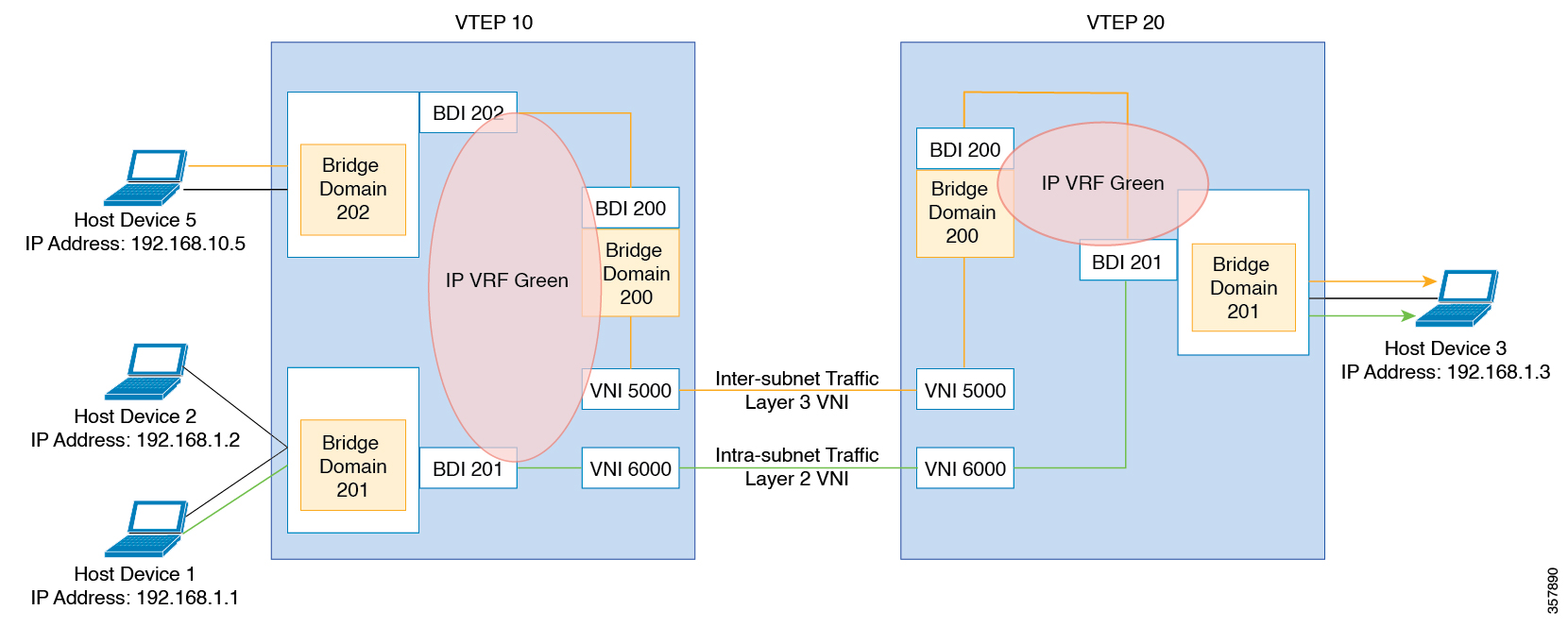
Depending on the subnets in which the hosts are configured, EVPN over VXLAN operates in two modes:

  • Bridged Mode:EVPN over VXLAN operates in Bridged mode when the hosts are in the same subnet. Intra-subnet trafffic moves seamlessly as it involves only a Layer 2 MAC lookup.

  • Routed Mode: EVPN over VXLAN operates in Routed mode when the hosts are in different subnets. Inter-subnet traffic involves Layer 2 MAC lookups and Layer 3 IP lookups.

This chapter provides a background for the evolution of the solution and covers conceptual information and basic terminology that is required to understand BGP EVPN VXLAN. Later chapters of this configuration guide include information about configuration, implementation, functionalities, and troubleshooting BGP EVPN VXLAN.


Note


This feature is supported only on Cisco ASR 1000 Series, Cisco Catalyst 8500 Edge Series platforms, and Cisco Catalyst 8000V Edge platform.


Benefits of Deploying Overlay-Underlay Architecture using BGP EVPN VXLAN

Deploying an overlay-underlay architecture using BGP EVPN VXLAN provides the following advantages:

  • Scalability: VXLAN provides Layer 2 connectivity that allows the infrastructure that can scale to 16 million tenant networks. It overcomes the 4094-segment limitation of VLANs. This is necessary to address today’s multitenant cloud requirements.

  • Flexibility: VXLAN allows workloads to be placed anywhere, along with the traffic separation required in a multitenant environment. Traffic separation is done using network segmentation (segment IDs or virtual network identifiers [VNIs]).Workloads for a tenant can be distributed across different physical devices (becouse workloads are added as the need arises, into the available server space), but the workloads are identified by the same Layer 2 or Layer 3 virtual network instance (VNI) as the case may be.

  • Mobility: VMs can be moved from one data center location to another without updating spine switch tables. This is because entities within the same tenant network in a EVPN VXLAN fabric setup retain the same segment ID, regardless of their location.

Limitations for BGP VXLAN EVPN

In Cisco IOS XE Release 17.11.1, the following limitations for BGP VXLAN EVPN are applicable only on Cisco ASR 1000 Series, Cisco Catalyst 8500 Edge Series platforms, and Cisco Catalyst 8000V Edge platform:

  • EVPN multihoming is not supported.

  • EVPN VXLAN IPV6 underlay is not supported.

  • Tenant Routed Multicast (TRM) features are not supported.

  • EVPN MAC address and IP learning from a static IPv4 ARP alias entry is supported. However, similar function for IPv6 ND is not supported.

Supported Features

Cisco IOS XE Release 17.11.1 supports the following features:

  • Distributed Anycast Gateway IP and MAC

  • EVI (MAC-VRF)

  • Local VLAN bridging

  • Cross Leaf VLAN over Layer 2 VNI

  • IRB (IP-VRF)

  • Local across BDI Layer 3 Routing

  • Cross-node Routing Over Layer 3 VNI

  • MAC Learing

    • Data Plane: Local MAC and IP learning

    • Control Plane: BGP EVPN route type 2

  • IP Mobility Detection for Host and Virtual Machine (VM) Move

  • MAC Mobility Detection for Host and VM Move

  • Address Resolution Protocol (ARP) and Neighbor Discovery Suppression

  • BGP EVPN IP Prefix Route Type 5

  • Ingress Replication

  • Underlay Multicast Replication

  • BD-VIF Support on Layer 2 EVPN

  • Layer 2 EVPN without EFP Interfaces and BDI Interface

  • MAC and IP Addressing learning from a static ARP alias entry

Fundamental Concepts of BGP EVPN VXLAN

This section provides information about the various fundamental concepts and terminologies that are involved in the working of BGP EVPN VXLAN.

EVPN VXLAN Distributed Anycast Gateway

Distributed Anycast Gateway (DAG) is a Default-gateway Addressing (DAC) mechanism in a BGP EVPN VXLAN fabric. This feature enables the use of the same gateway IP address and MAC address across all the VETPs in an EVPN VXLAN network. This ensures that every VTEP functions as the default gateway for the workloads directly connected to it. This feature facilitates flexible workload placement, host mobility, and optimal traffic forwarding across the BGP EVPN VXLAN fabric.

The scenario shown in the figure 1 depicts a distributed gateway. Subnet 1 contains two leaf nodes—leaf node 1 and leaf node 2, acting together as a distributed default gateway for VLAN 10. Host device 1 is connected to leaf node 1 and sends traffic to host device 3, which is in a different subnet. When host device 1 tries to send traffic outside of subnet 1, the traffic goes through the configured gateway in leaf node 1. Host device 1 registers the Address Resolution Protocol (ARP) entries of the gateway VLAN MAC and IP address in leaf node 1.

When multiple VETPs act together as a single distributed default gateway for the same VLAN, the VLAN IP address remains the same across all of them. This IP address becomes the gateway IP address for any host device in the VLAN that tries to reach an IP address outside its subnet. But, each VTEP retains its own MAC address.
Figure 1. An EVPN VXLAN Network with Distributed Gateway

In the preceding figure, consider a scenario where host device 1 moves from leaf node 1 to leaf node 2. The host device remains within the same network and maintains the same ARP entries for gateway MAC addresses and IP addresses. But the MAC addresses of the VLAN interfaces in leaf node 2 and leaf node 1 are different. This results in a MAC address mismatch between the ARP entry and the VLAN on leaf node 2. As a result, any traffic that Host device 1 tries to send outside of Subnet 1 is either lost or continuously flooded as unknown unicast. The EVPN VXLAN Distributed Anycast Gateway feature prevents this traffic loss by ensuring that all the VTEPs have the same gateway MAC addresses and IP addresses in BDI.

Manual MAC address configuration and MAC aliasing are the two methods used to maintain the same MAC address across all the VTEPs and configure distributed anycast gateway.

EVPN VXLAN Centralized Gateway

In Centralized Gateway (CGW), the network has a CGW VTEP that performs the Layer 3 gateway function for all the Layer 2 VNIs. All the other VTEPs in the network perform only bridging. The CGW VTEP acts as the Layer 3 gateway and performs routing for the intersubnet VXLAN traffic.

The CGW VTEP advertises the BDI MAC-IP route for a particular VXLAN-enabled VLAN to all other Layer 2 VTEPs that have the same Layer 2 VNI configured. This allows the VTEPs to import and install the remote BDI MAC-IP route as a VXLAN Layer 3 gateway address. A host device uses the address of a BDI in the same VLAN on the CGW VTEP as its gateway address. Configure the BDI for the Layer 2 VNI VLAN only on the CGW VTEP. Do not configure the BDI (for the respective Layer 2 VNI VLAN) on any other VTEP in the network that acts as a Layer 2 VTEP.

When a host device connected to a Layer 2 VTEP sends traffic to a different subnet, the traffic is bridged from the Layer 2 VTEP to the CGW VTEP. The CGW VTEP then routes the traffic to the destination subnet. The destination subnet can be another VXLAN-enabled VLAN or an external route.

If the CGW VTEP needs to route the traffic between 2 VXLAN-enabled VLANs, configure the CGW on the same VTEP for both VLANs. In other words, configure the BDI on the same VTEP for both VLANs.

We recommend that you configure a centralized default gateway in an EVPN VXLAN network if:

  • You require a boundary between the Layer 2 and Layer 3 segments at the border of the BGP EVPN VXLAN fabric.

  • The intersubnet traffic is subjected to a firewall inspection or any policy on a centralized plane.


Note


Toggling between DAG and CGW on a BDI in a VLAN disrupts the traffic for that VLAN.


The following image shows an EVPN VXLAN network with the centralized default gateway configured.

Figure 2. An EVPN VXLAN Network with Centralized Default Gateway

For configuration details, see Example: Configuring the EVPN VXLAN Centralized Gateway.

Information About EVPN VXLAN Integrated Routing and Bridging

EVPN VXLAN integrated routing and bridging (IRB) allows the VTEPs or leaf switches in an EVPN VXLAN network to perform both bridging and routing. IRB allows the VTEPs to forward both Layer 2 or bridged traffic and Layer 3 or routed traffic. A VTEP performs bridging when it forwards traffic to the same subnet. Similarly, a VTEP performs routing when it forwards traffic to a different subnet. The VTEPs in the network forward traffic to each other through the VXLAN gateways. BGP EVPN VXLAN implements IRB using symmetric IRB.

Symmetric IRB

In symmetric IRB, both the ingress and egress VTEPs perform both bridging and routing. A packet first moves through a MAC VRF, followed by an IP VRF on the NVE of the ingress VTEP. It then moves through an IP VRF followed by a MAC VRF on the NVE of the egress VTEP. The NVEs of ingress and egress VTEPs equally share all the packet processing associated with intersubnet forwarding semantics.

In symmetric IRB, you are required to define only the VNIs of locally attached endpoints in the ingress and egress VTEPs. Symmetric IRB offers better scalability in terms of the number of VNIs that a BGP EVPN VXLAN fabric supports.

The following figure shows the implementation of symmetric IRB and the movement of traffic in an EVPN VXLAN network:

Figure 3. EVPN VXLAN Integrated Routing and Bridging
Traffic flow in EVPN VXLAN network when Symmetric IRB is configured.

For configuration details, see Example: Configuring EVPN VXLAN Integrated Routing and Bridging.

Default Gateway MAC Address Assignment

When leaf switches import gateway addresses, it can result in a conflict if the BDI of a leaf switch has the same IP address and MAC address as the imported addresses. To avoid this conflict, the BDI MAC-IP routes are tagged with the Default Gateway Extended Community attribute. The attribute helps the receiving leaf switches to distinguish the MAC-IP routes of the BDIs from the MAC-IP routes of the host devices. When a leaf switch receives a route tagged with the Default Gateway Extended Community attribute, it results in one of the following scenarios:

  • If the leaf switch does not have a local BDI for the same MAC VRF, it installs the route only as a remote MAC route. The leaf switch implements the centralized gateway functionality in this scenario.

  • If the leaf switch has a local BDI with a matching IP address but different MAC address, it installs the MAC route as a route that points to the local BDI. The leaf switch implements MAC aliasing for distributed anycast gateway in this scenario.

  • If the leaf switch has an BDI with no matching IP address, it invalidates the MAC-IP route and issues an error. See RFC4732 for more details about the error.

Broadcast, Unknown Unicast, and Multicast Traffic

Multidestination Layer 2 traffic in a VXLAN network is typically referred to as broadcast, unknown unicast, and multicast (BUM) traffic. In a BGP EVPN VXLAN fabric, the underlay network forwards the BUM traffic to all the endpoints connected to a common Layer 2 broadcast domain in the VXLAN overlay.

The following image shows the flow of BUM traffic through a Layer 2 VNI. The network forwards BUM traffic from host device 1 to all the VTEPs which then send the traffic to all the host devices in the same subnet.

Figure 4. BUM Traffic through Layer 2 VNI

Ingress Replication

Ingress replication, or headend replication, is a unicast approach to handle multidestination Layer 2 overlay BUM traffic. Ingress replication involves an ingress device replicating every incoming BUM packet and sending them as a separate unicast to the remote egress devices. Ingress replication happens through EVPN route type 3, also called inclusive multicast ethernet tag (IMET) route. BGP EVPN ingress replication uses IMET route for auto discovery of remote peers in order to set up the BUM tunnels over VXLAN. Using ingress replication to handle BUM traffic can result in scaling issues because an ingress device needs to replicate the BUM traffic as many times as there are VTEPs associated with the Layer 2 VNI.

Ingress Replication Operation

IMET routes carry the remote or egress VNIs advertised from the remote peers, which can be different from the local VNI. The network creates a VXLAN tunnel adjacency when an ingress device receives IMET ingress replication routes from remote NVE peers. The tunnel adjacency is a midchain adjacency that contains IP or UDP encapsulation for the VXLAN tunnel. If there is more than one VNI along the tunnel, multiple VNIs share the tunnel. Ingress replication on EVPN can have multiple unicast tunnel adjacencies and different egress VNIs for each remote peer.

The network builds a flooded replication list with the routes advertised by each VTEP. The dynamic replication list stores all the remote destination peers discovered on a BGP IMET route in the same Layer 2 VNI. The replication list gets updated every time you configure the Layer 2 VNI at a remote peer. The network removes the tunnel adjacency and VXLAN encapsulation from the replication list every time a remote NVE peer withdraws the IMET ingress replication route. The network deletes the tunnel adjacency when no NVE peer is using it.

Any BUM traffic that reaches the ingress device gets replicated after the replication list is built. The ingress device forwards the replicated traffic throughout the network to all the remote peers in the same VNI.

Underlay Multicast

In underlay multicast, the underlay network replicates the traffic through a multicast group in PIM sparse mode. Forwarding BUM traffic using underlay multicast requires the configuration of IP multicast in the underlay network. A single copy of the BUM traffic moves from the ingress or source VTEP towards the underlay transport network. The network forwards this copy along the multicast tree so that it reaches all egress or destination VTEPs participating in the given multicast group. Various branch points in the network replicate the copy as it travels along the multicast tree. The branch points replicate the copy only if the receivers are part of the multicast group associated with the VNI.

BUM traffic forwarding through underlay multicast is achieved by mapping a Layer 2 VNI to the multicast group. This mapping must be configured on all the VTEPs associated with the Layer 2 VNI. When a VTEP joins the multicast group, it receives all the traffic that is forwarded on that group. If the VTEP receives traffic in a VNI that is not associated with it, it simply drops the traffic. This approach maintains a single link within the network, thus providing an efficient way to forward BUM traffic.

Flooding Suppression

EVPN allows the distribution of the binding between IPv4 or IPv6 addresses and MAC addresses among the VTEPs of the network. It distributes the MAC-IP binding among all the VTEPs that participate in the EVPN instance associated with the MAC-IP routes. The MAC address associated with the IPv4 or IPv6 addresses is locally known even though it is learned from a remote VTEP. Locally connected endpoints send an Address Resolution Protocol (ARP) or an IPv6 neighbor discovery request when they look for a remote endpoint. The MAC-IP binding distribution allows a VTEP to perform a lookup in the local cache when it receives an ARP or an IPv6 neighbor discovery request. If the MAC-IP address information for the remote end point is available, the VTEP uses this information to avoid flooding the ARP request or IPv6 neighbor discovery request. If the MAC or IP address information for the remote end point is not available, the request floods throughout the fabric.

Flooding suppression avoids the flooding of ARP and IPv6 neighbor discovery packets over the EVPN VXLAN network. It suppresses the flooding to both the local and remote host or access devices. The network suppresses flooding by implementing an ARP or neighbor discovery relay. This is achieved by using the known MAC address for the specified IPv4 or IPv6 address to convert broadcast and multicast requests to unicast requests. Flooding suppression is enabled by default on an EVPN-enabled VLAN. An EVPN VXLAN network suppresses the flooding for the following types of traffic.

ARP Flooding Suppression

VTEPs send ARP requests as broadcast packets. ARP requests represent a large percentage of Layer 2 broadcast traffic. Flooding suppression converts them to unicast packets and reduces the network flood.


Note


An ARP packet will not be generated from a BD-VIF interface or BDI interface if MAC and IP binding is found in EVPN database on the source (ingress) VTEP.


To avoid sending an ARP and neighbor discovery request, you must apply the ARP and neighbor discovery entries on the BDI or BD-VIF associated VRFs based on the remotely learned RT-2 routes or local learned MAC or IP bindings. It helps to reduce the overall traffic and system load caused by broadcast ARP packets.

When an ARP originates from a BD-VIF or BDI interface, an ARP entry is installed directly if a MAC or IP binding is available for the target IP address in the EVPN database, without even sending a unicast ARP packet.

This behavior only limit to L2-EVPN configured with BD-VIF interface.

IPv6 Neighbor Discovery Flooding Suppression

The IPv6 neighbor discovery process enables the discovery of a neighbor and helps the peers to determine each other's link-layer addresses. It also verifies the reachability of a neighbor and tracks the neighboring routers. IPv6 neighbor discovery uses Internet Control Message Protocol (ICMP) messages and solicited-node multicast addresses to achieve these functions.

Flooding suppression suppresses all multicast neighbor solicitation packets among Internet Control Message Protocol version 6 (ICMPv6) packets.

Bridge Domain VIF Support on Layer 2 EVPN

The Layer 2 EVPN only supports BDI interface that is attached to a EVPN Layer 2 network as an interface to a routing domain. The BDI servers as a centralized gateway or distributed anycast gateway in Symmetric IRB model.

Figure 5. EVPN VxLAN on Layer 2 VTEP

In some scenarios, one or more bridge domain-VIF (BD-VIF) interfaces are attached to a single EVPN Layer 2 network. Also, a BD-VIF interface is recognized by the Layer 2 EVPN network as a regular routing interface. This interface can be used as a Unicast Centralized Gateway for all, or a portion of routing-bound traffic. If you configure multiple BD-VIF interface, each bridge domain-VIF must belong to different routing domain (VRF), and should have a unique gateway IP address across the same Layer 2 EVPN network. In this scenario, hosts of the Layer 2 EVPN network can be configured to use different BD-VIF interface as a gateway.

Figure 6. EVPN VxLAN on Layer 2 VTEP-2

When a BDI interface and multiple BD-VIF interfaces co-exist within one Layer 2 EVPN network, the BDI interface must be configured as IRB interface. The other BD-VIF interfaces are treated as interfaces towards other routing domains, or gateways for VM-bound traffic.

The IP address and MAC-IP binding of a BD-VIF interface is learned and advertised as regular host RT2 route, without carrying Default-Gateway Extended Community attribute.

MAC and IP Addressing Learning from a Static ARP Alias Entry

With the new functionalities, EVPN VxLAN can learn a EVPN MAC/IP binding from a static ARP alias entries immediately after the ARP alias is configured. After learning the MAC/IP binding, a EVPN route type 2 is advertised across the EVPN network. For routing purpose, the route type 2 is imported to IP VRF in remote devices as a host IP route for the IP address. A packet bound to this IP address is forwarded over Layer 3 VNI to IP VRF in the destination device.The feature enables the use of the same gateway MAC address as the RT-2 route that is advertised for BD-VIF interface MAC/IP address across all the EVPN VXLAN network.

How to Configure EVPN VXLAN Layer 2 Overlay Network

The following figure shows a sample topology of an EVPN VXLAN Network. Host device 1 and host device 3 are part of the same subnet. The network forwards BUM traffic from host device 1 to host device 3 using a Layer 2 VNI through either underlay multicast or ingress replication methods.

EVPN VXLAN sample topology

Note


In a two-VTEP topology, a spine switch is not mandatory. For information about configuration of spine switches in an EVPN VXLAN network, see Configuring Spine Switches in a BGP EVPN VXLAN Fabric module.


Perform the following set of procedures to configure an EVPN VXLAN Layer 2 overlay network:

  1. Configure BGP with EVPN address family on the VTEPs.

  2. Configure Layer 2 VPN EVPN on the VTEPs.

  3. Configure an EVPN instance in the VLAN on the VTEPs.

  4. Configure the access-facing interface in the VLAN on the VTEPs.

  5. Configure the loopback interface on the VTEPs.

  6. Configure the network virtualization endpoint (NVE) interface on the VTEPs.

Configuring BGP with EVPN Address Family on a VTEP

To configure BGP with EVPN address family on the VTEPs and with a spine switch as the neighbor, perform the following steps:

SUMMARY STEPS

  1. enable
  2. configure terminal
  3. router bgp autonomous-system-number
  4. neighbor ip-address remote-as number
  5. neighbor { ip-address | group-name} update-source interface
  6. address-family l2vpn evpn
  7. neighbor ip-address activate
  8. neighbor ip-address send-community [ both | extended | standard]
  9. exit-address-family
  10. end

DETAILED STEPS

  Command or Action Purpose

Step 1

enable

Example:

Device> enable

Enables privileged EXEC mode.

Enter your password, if prompted.

Step 2

configure terminal

Example:

Device# configure terminal

Enters global configuration mode.

Step 3

router bgp autonomous-system-number

Example:

Device(config)# router bgp 1

Enables a BGP routing process, assigns it an autonomous system number, and enters router configuration mode.

Step 4

neighbor ip-address remote-as number

Example:

Device(config-router)# neighbor 11.11.11.11 remote-as 1

Defines multiprotocol BGP neighbors. Under each neighbor, define the Layer 2 Virtual Private Network (L2VPN) EVPN configuration.

Use the IP address of the spine switch as the neighbor IP address.

Step 5

neighbor { ip-address | group-name} update-source interface

Example:

Device(config-router)# neighbor 11.11.11.11 update-source Loopback0

Configures update source. Update source can be configured per neighbor or per peer group.

Use the IP address of the spine switch as the neighbor IP address.

Step 6

address-family l2vpn evpn

Example:

Device(config-router)# address-family l2vpn evpn

Specifies the L2VPN address family and enters address family configuration mode.

Step 7

neighbor ip-address activate

Example:

Device(config-router-af)# neighbor 11.11.11.11 activate

Enables the exchange information from a BGP neighbor.

Use the IP address of the spine switch as the neighbor IP address.

Step 8

neighbor ip-address send-community [ both | extended | standard]

Example:

Device(config-router-af)# neighbor 11.11.11.11 send-community both

Specifies the communities attribute sent to a BGP neighbor.

Use the IP address of the spine switch as the neighbor IP address.

Step 9

exit-address-family

Example:

Device(config-router-af)# exit-address-family

Exits address family configuration mode and returns to router configuration mode.

Step 10

end

Example:

Device(config-router)# end

Returns to privileged EXEC mode.

Configuring Layer 2 VPN EVPN on a VTEP

To configure the L2VPN EVPN parameters on a VTEP, perform the following steps:

SUMMARY STEPS

  1. enable
  2. configure terminal
  3. l2vpn evpn
  4. encapsulation vxlan
  5. replication-type { ingress| static}
  6. exit
  7. end

DETAILED STEPS

  Command or Action Purpose

Step 1

enable

Example:

Device> enable

Enables privileged EXEC mode.

Enter your password, if prompted.

Step 2

configure terminal

Example:

Device# configure terminal

Enters global configuration mode.

Step 3

l2vpn evpn

Example:

Device(config)# l2vpn evpn

Enters EVPN configuration mode.

Step 4

encapsulation vxlan

Example:

Device(config-evpn)# encapsulation vxlan

(Optional) Defines the encapsulation format as VXLAN. The encapsulation is VXLAN by default.

.

Step 5

replication-type { ingress| static}

Example:

Device(config-evpn)# replication-type ingress

Sets the replication type for the EVPN instance.

Note


Configure the L2VPN EVPN replication type as static, if multicast is enabled in the underlay network for EVPN BUM traffic.

When the L2VPN EVPN replication type is configured as static, the Inclusive Multicast Ethernet Tag (IMET) route is not advertised, and forwarding of BUM traffic relies on underlay multicast being configured on each VTEP.

Step 6

exit

Example:

Device(config-evpn)# exit

Exits EVPN configuration mode and enters global configuration mode.

Step 7

end

Example:

Device(config-evpn)# end

Returns to privileged EXEC mode.

Configuring an EVPN Instance in Bridge Domain on a VTEP

To configure an EVPN instance on a VTEP, perform the following steps:

SUMMARY STEPS

  1. enable
  2. configure terminal
  3. bridge-domain bridge-id
  4. member interface-name service-instance number
  5. member evpn-instance evpn-instance-id vni l2-vni-number
  6. exit
  7. end

DETAILED STEPS

  Command or Action Purpose

Step 1

enable

Example:

Device> enable

Enables privileged EXEC mode.

Enter your password, if prompted.

Step 2

configure terminal

Example:

Device# configure terminal

Enters global configuration mode.

Step 3

bridge-domain bridge-id

Example:

Device(config)# bridge-domain 123

Configures the bridge domain ID.

  • bridge-id: Bridge domain number. The bridge domain number varies depending on the platform. For Cisco ASR 1000 Series, the valid range is from 1 to 16000. For Cisco Catalyst 8000V Edge platform, the valid range is from 1 to 8192.

Step 4

member interface-name service-instance number

Example:

Device(config-bdomain)# member GigabitEthernet1/3/1 service-instance 1000

Configures the interface for the bridge domain.

Step 5

member evpn-instance evpn-instance-id vni l2-vni-number

Example:

Device(config-bdomain)# member evpn-instance 23 vni 20123

Adds EVPN instance as a member of the bridge domain configuration.

The VNI here is used as an L2VNI.

Step 6

exit

Example:

Device(config-evpn-evi)# exit

Exits EVPN configuration mode and enters global configuration mode.

Step 7

end

Example:

Device(config-evpn)# end

Returns to privileged EXEC mode.

Configuring the NVE Interface on a VTEP

To add a VNI member to the NVE interface of a VTEP, perform the following steps:

SUMMARY STEPS

  1. enable
  2. configure terminal
  3. interface nve nve-interface-id
  4. host-reachability protocol bgp
  5. source-interface loopback-interface-id
  6. member vni layer2-vni-id { ingress-replication| mcast-group}< multicast group-address> }
  7. end

DETAILED STEPS

  Command or Action Purpose

Step 1

enable

Example:

Device> enable

Enables privileged EXEC mode.

Enter your password, if prompted.

Step 2

configure terminal

Example:

Device# configure terminal

Enters global configuration mode.

Step 3

interface nve nve-interface-id

Example:

Device(config)# interface nve 1

Defines the interface to be configured as a trunk, and enters interface configuration mode.

Step 4

host-reachability protocol bgp

Example:

Device(config-if)# host-reachability protocol bgp

Configures BGP as the host-reachability protocol on the interface.

Note


You must configure the host-reachability protocol on the interface. If you do not execute this step, the VXLAN tunnel defaults to static VXLAN tunnel, which is currently not supported on the device.

Step 5

source-interface loopback-interface-id

Example:

Device(config-if)# source-interface loopback0

Sets the IP address of the specified loopback interface as the source IP address.

Step 6

member vni layer2-vni-id { ingress-replication| mcast-group}< multicast group-address> }

Example:

Device(config-if)# member vni 39000 ingress-replication

Associates the Layer 2 VNI member with the NVE.

The specified replication type must match the replication type that is configured globally, or for the specific EVPN instance. Use the ingress-replication keyword for ingress replication. Use mcast-group followed by a multicast group address keywords for static multicast replication.

Step 7

end

Example:

Device(config-if)# end

Returns to privileged EXEC mode.

How to Configure EVPN VXLAN Layer 2 and Layer 3 Overlay Network

The following sections provide detailed information about the various tasks that must be performed to configure an EVPN VXLAN Layer 2 and Layer 3 overlay network.

Configuring BGP on a VTEP with EVPN Address Family

To configure BGP on a VTEP with EVPN address family and with spine switch as the neighbor, perform the following steps:

SUMMARY STEPS

  1. enable
  2. configure terminal
  3. router bgp autonomous-system-number
  4. neighbor ip-address remote-as number
  5. neighbor { ip-address | group-name} update-source interface
  6. address-family l2vpn evpn
  7. neighbor ip-address activate
  8. neighbor ip-address send-community [ both | extended | standard]
  9. exit-address-family
  10. address-family ipv4[ mdt] { multicast | unicast} { vrf vrf name}
  11. advertise l2vpn evpn
  12. exit-address-family
  13. end

DETAILED STEPS

  Command or Action Purpose

Step 1

enable

Example:

Device> enable

Enables privileged EXEC mode.

Enter your password, if prompted.

Step 2

configure terminal

Example:

Device# configure terminal

Enters global configuration mode.

Step 3

router bgp autonomous-system-number

Example:

Device(config)# router bgp 1

Enables a BGP routing process, assigns it an autonomous system number, and enters router configuration mode.

Step 4

neighbor ip-address remote-as number

Example:

Device(config-router)# neighbor 11.11.11.11 remote-as 1

Defines multiprotocol BGP neighbors. Under each neighbor, define the Layer 2 Virtual Private Network (L2VPN) EVPN configuration.

Use the IP address of the spine switch as the neighbor IP address.

Step 5

neighbor { ip-address | group-name} update-source interface

Example:

Device(config-router)# neighbor 11.11.11.11 update-source Loopback0

Configures update source. Update source can be configured per neighbor or per peer group.

Use the IP address of the spine switch as the neighbor IP address.

Step 6

address-family l2vpn evpn

Example:

Device(config-router)# address-family l2vpn evpn

Specifies the L2VPN address family and enters address family configuration mode.

Step 7

neighbor ip-address activate

Example:

Device(config-router-af)# neighbor 11.11.11.11 activate

Enables the exchange information from a BGP neighbor.

Use the IP address of the spine switch as the neighbor IP address.

Step 8

neighbor ip-address send-community [ both | extended | standard]

Example:

Device(config-router-af)# neighbor 11.11.11.11 send-community both

Specifies the communities attribute sent to a BGP neighbor.

Use the IP address of the spine switch as the neighbor IP address.

Step 9

exit-address-family

Example:

Device(config-router-af)# exit-address-family

Exits address family configuration mode and returns to router configuration mode.

Step 10

address-family ipv4[ mdt] { multicast | unicast} { vrf vrf name}

Example:

Device(config-router)# address-family ipv4 vrf Customer1

Enters address family configuration mode to configure a routing session using standard IP Version 4 (IPv4) address prefixes.

Step 11

advertise l2vpn evpn

Example:

Device(config-router-af)# advertise l2vpn evpn

Advertises the L2VPN EVPN routes to the EVPN BGP neighbor.

Step 12

exit-address-family

Example:

Device(config-router-af)# exit-address-family

Exits address family configuration mode and returns to router configuration mode.

Step 13

end

Example:

Device(config-router)# end

Returns to privileged EXEC mode.

Configuring the IP VRF on a VTEP

To add a VNI member to the NVE interface of a VTEP, perform the following steps:

SUMMARY STEPS

  1. enable
  2. configure terminal
  3. vrf definition vrf name
  4. rd route-distinguisher
  5. address-family ipv4 { multicast | unicast} { vrfvrf name}
  6. route-target export route-target-id stitching
  7. route-target import route-target-id stitching
  8. exit-address-family
  9. end

DETAILED STEPS

  Command or Action Purpose

Step 1

enable

Example:

Device> enable

Enables privileged EXEC mode.

Enter your password, if prompted.

Step 2

configure terminal

Example:

Device# configure terminal

Enters global configuration mode.

Step 3

vrf definition vrf name

Example:

Device(config)# vrf definition red

Names the VRF and enters VRF configuration mode.

Step 4

rd route-distinguisher

Example:

Device(config-vrf)# rd 1.1.1.1:1

(Optional) Creates a VRF table by specifying a route distinguisher. Enter either an Autonomous System number and an arbitrary number (xxx:y) or an IP address and arbitrary number (A.B.C.D:y).

Step 5

address-family ipv4 { multicast | unicast} { vrfvrf name}

Example:

Device(config-router)# address-family ipv4 unicast

Enters address family configuration mode to configure a routing session using standard IP Version 4 (IPv4) address prefixes.

Step 6

route-target export route-target-id stitching

Example:

Device(config-if-afi)# route-target export 100:1 stitching

Configures exporting of routes from the VRF to the EVPN BGP NLRIs and assigns the specified route-target identifiers to the BGP EVPN nodes, links, or prefixes (NLRIs).

Step 7

route-target import route-target-id stitching

Example:

Device(config-if-afi)# route-target import 100:1 stitching

Configures importing of routes from the EVPN BGP NLRI that have the matching route-target value.

Step 8

exit-address-family

Example:

Device(config-router-afi)# exit-address-family

Exits address family configuration mode and returns to router configuration mode.

Step 9

end

Example:

Device(config-if)# end

Returns to privileged EXEC mode.

Configuring the Per-EVI Bridge Domain on a VTEP

To configure the Per-EVI bridge domain on a VTEP, perform the following steps:

SUMMARY STEPS

  1. enable
  2. configure terminal
  3. bridge-domain bridge-id
  4. member evpn-instance evpn-instance-id vni l2-vni-number
  5. member interface-name service-instance number
  6. exit
  7. interface interface-name
  8. service instance number ethernet
  9. encapsulation dot1q<first tag> [second dot1q <second tag>]
  10. exit

DETAILED STEPS

  Command or Action Purpose

Step 1

enable

Example:

Device> enable

Enables privileged EXEC mode.

Enter your password, if prompted.

Step 2

configure terminal

Example:

Device# configure terminal

Enters global configuration mode.

Step 3

bridge-domain bridge-id

Example:

Device(config)# bridge-domain 10

Configure the bridge domain ID. The range is from 1 to 4000.

  • bridge-id: Bridge domain number. The valid range is from 1 to 4094.

Step 4

member evpn-instance evpn-instance-id vni l2-vni-number

Example:

Device(config-bdomain)# member evpn-instance 1 vni 39000

Adds EVPN instance as a member of the bridge domain configuration.

The VNI here is used as a Layer 2 VNI.

Step 5

member interface-name service-instance number

Example:

Device(config-bdomain)# member GigabitEthernet0/1/0 service-instance 10

Configures the interface for the bridge domain.

Step 6

exit

Example:

Device(onfig-bdomain)# exit

Returns to privileged EXEC mode.

Step 7

interface interface-name

Example:

Device(config)# interface GigabitEthernet0/1/1

Enters interface configuration mode for the specified interface.

Step 8

service instance number ethernet

Example:

Device(config-if)# service-instance 10 ethernet

Configures an EFP (service instance) and enters service instance configuration mode.

  • number: EFP identifier; an integer from 1 to 4000.

Step 9

encapsulation dot1q<first tag> [second dot1q <second tag>]

Example:

Device(config-if-srv)# encapsulation dot1q 10

Configures encapsulation type for the service instance.

Step 10

exit

Example:

Device(onfig-if-srv)# exit

Returns to privileged EXEC mode.

Configuring a Bridge Domain Interface Using Anycast IP and MAC Address in All Leafs

To configure a bridge domain interface using the same IP address and Mac address in all the leafs, perform the following steps:

SUMMARY STEPS

  1. enable
  2. configure terminal
  3. interface BDI { interface number }
  4. mac address { mac-address }
  5. vrf forwarding vrf name
  6. ip address ip address mask
  7. exit

DETAILED STEPS

  Command or Action Purpose

Step 1

enable

Example:

Device> enable

Enables privileged EXEC mode.

Enter your password, if prompted.

Step 2

configure terminal

Example:

Device# configure terminal

Enters global configuration mode.

Step 3

interface BDI { interface number }

Example:

Device(config)# interface BDI 12

Specifies a bridge domain interface.

Step 4

mac address { mac-address }

Example:

Device(config-if)# mac-address 1.1.1

Specifies the MAC address for the bridge domain interface.

Step 5

vrf forwarding vrf name

Example:

Device(config-if)# vrf forwarding red

Associates the VRF with the Layer 3 interface.

Step 6

ip address ip address mask

Example:

Device(config-if)# ip address 2.2.2.254 255.255.255.0

Specifies either the IPv4 or IPv6 address for the bridge domain interface.

Step 7

exit

Example:

Device(config-if)# exit

Returns to privileged EXEC mode.

Configuring Bridge Domain for a Layer 3 VXLAN on a VRF

To configure a bridge domain on a vrf, perform the following steps:

SUMMARY STEPS

  1. enable
  2. configure terminal
  3. bridge-domain bridge-id
  4. member vni l3-vni-number
  5. exit
  6. interface BDI { interface number }
  7. vrf forwarding vrf name
  8. ip address ip address mask
  9. exit

DETAILED STEPS

  Command or Action Purpose

Step 1

enable

Example:

Device> enable

Enables privileged EXEC mode.

Enter your password, if prompted.

Step 2

configure terminal

Example:

Device# configure terminal

Enters global configuration mode.

Step 3

bridge-domain bridge-id

Example:

Device(config)# bridge-domain 3

Configure the bridge domain ID.

  • bridge-id: Bridge domain number. The bridge domain number depends on the platform. For Cisco ASR 1000 Series, the valid range is from 1 to 16000. For Cisco Catalyst 8000V Edge platform, the valid range is from 1 to 8192.

Step 4

member vni l3-vni-number

Example:

Device(config-bdomain)# member vni 49000

Associates the Layer 3 VNI member with the bridge domain configuration.

Step 5

exit

Example:

Device(onfig-bdomain)# exit

Returns to privileged EXEC mode.

Step 6

interface BDI { interface number }

Example:

Device(config)# interface BDI 3

Specifies a bridge domain interface.

Step 7

vrf forwarding vrf name

Example:

Device(config-if)# vrf forwarding red

Associates the VRF with the Layer 3 interface.

Step 8

ip address ip address mask

Example:

Device(config-if)# ip address 20.20.20.20 255.255.255.255

Specifies either the IPv4 or IPv6 address for the bridge domain interface.

Step 9

exit

Example:

Device(config-if)# exit

Returns to privileged EXEC mode.

Configuring the NVE Interface on a VTEP

To configure a VNI member to the NVE interface of a VTEP, perform the following steps:

SUMMARY STEPS

  1. enable
  2. configure terminal
  3. interface nve nve-interface-id
  4. host-reachability protocol bgp
  5. source-interface loopback-interface-id
  6. member vni layer2-vni-id { ingress-replication}
  7. member vni l3-vni-number vrf name
  8. exit

DETAILED STEPS

  Command or Action Purpose

Step 1

enable

Example:

Device> enable

Enables privileged EXEC mode.

Enter your password, if prompted.

Step 2

configure terminal

Example:

Device# configure terminal

Enters global configuration mode.

Step 3

interface nve nve-interface-id

Example:

Device(config)# interface nve 1

Defines the interface to be configured as a trunk, and enters interface configuration mode.

Step 4

host-reachability protocol bgp

Example:

Device(config-if)# host-reachability protocol bgp

Configures BGP as the host-reachability protocol on the interface.

Note


You must configure the host-reachability protocol on the interface. If you do not execute this step, the VXLAN tunnel defaults to static VXLAN tunnel, which is currently not supported on the device.

Step 5

source-interface loopback-interface-id

Example:

Device(config-if)# source-interface loopback0

Sets the IP address of the specified loopback interface as the source IP address.

Step 6

member vni layer2-vni-id { ingress-replication}

Example:

Device(config-if)# member vni 5011 ingress-replication

Associates the Layer 2 VNI member with the NVE.

The specified replication type must match the replication type that is configured globally, or for the specific EVPN instance. Use the mcast-group keyword for static replication and the ingress-replication keyword for ingress replication.

Step 7

member vni l3-vni-number vrf name

Example:

Device(config-if)# member vni 49000 vrf red

Adds EVPN instance for the interface.

The VNI here is used as a Layer 3 VNI.

Step 8

exit

Example:

Device(config-if)# exit

Returns to privileged EXEC mode.

Configuring Underlay Multicast Group

SUMMARY STEPS

  1. enable
  2. configure terminal
  3. interface nve nve-interface-id
  4. source-interface loopback-interface-id
  5. host-reachability protocol bgp
  6. member vni layer2-vni-id { ingress-replication | mcast-group <mcast-group-id> }
  7. exit
  8. l2vpn evpn instance evpn-instance-number vlan-based
  9. encapsulation vxlan
  10. replication-type { static}
  11. default-gateway advertise { enable | disable }
  12. end

DETAILED STEPS

  Command or Action Purpose

Step 1

enable

Example:

Device> enable

Enables privileged EXEC mode.

Enter your password, if prompted.

Step 2

configure terminal

Example:

Device# configure terminal

Enters global configuration mode.

Step 3

interface nve nve-interface-id

Example:

Device(config)# interface nve 1

Defines the interface and enters interface configuration mode.

Step 4

source-interface loopback-interface-id

Example:

Device(config-if)# source-interface loopback0

Sets the IP address of the specified loopback interface as the source IP address.

Step 5

host-reachability protocol bgp

Example:

Device(config-if)# host-reachability protocol bgp

Configures BGP as the host-reachability protocol on the interface.

Note


You must configure the host-reachability protocol on the interface. If you do not execute this step, the VXLAN tunnel defaults to static VXLAN tunnel, which is currently not supported on the device.

Step 6

member vni layer2-vni-id { ingress-replication | mcast-group <mcast-group-id> }

Example:

Device(config-if)# member vni 3017000 mcast-group 239.1.1.1

Associates the Layer 2 VNI member with the NVE.

The specified replication type must match the replication type that is configured globally or for the specific EVPN instance.

Use mcast-group keyword for static replication and ingress-replication keyword for ingress replication.

Step 7

exit

Example:

Device(config-if)# exit

Exits interface configuration mode and enters global configuration mode.

Step 8

l2vpn evpn instance evpn-instance-number vlan-based

Example:

Device(config)# l2vpn evpn instance 1700 vlan-based

Enters EVPN configuration mode and configures VLAN-based instance.

Step 9

encapsulation vxlan

Example:

Device(config-evpn)# encapsulation vxlan

(Optional) Defines the encapsulation format as VXLAN.The encapsulation format is VXLAN by default.

.

Step 10

replication-type { static}

Example:

Device(config-evpn)# replication-type static

Sets the replication type for the EVPN instance.

Note


Configure the L2VPN EVPN replication type as static, if multicast is enabled in the underlay network for EVPN BUM traffic.

When the L2VPN EVPN replication type is configured as static, the IMET route is not advertised and forwarding of BUM traffic relies on underlay multicast being configured on each VTEP.

Step 11

default-gateway advertise { enable | disable }

Example:

Device(config-evpn))# default-gateway advertise disable

(Optional) Enables or disables the default gateway advertisement for the EVPN instance. In case default gateway advertisement has already been globally configured, this overrides the global setting. This command is mandatory only if the same MAC address is not manually configured on all the access SVIs. To configure distributed anycast gateway in a VXLAN network using MAC aliasing, enable default gateway advertisement on all the leaf switches in the network

Step 12

end

Example:

Device(config-evpn)# end

Returns to privileged EXEC mode.

Configuring a NAT and ARP Alias

To configure the bridge domain VIF interfaces as NAT inside interface or outside interface, perform the following steps:

SUMMARY STEPS

  1. enable
  2. configure terminal
  3. interface BD-VIF unit number
  4. ip vrf forwarding vrf-name
  5. ip address ip address subnet mask
  6. ip nat inside
  7. exit
  8. interface BD-VIF unit number
  9. ip vrf forwarding vrf-name
  10. ip address ip address subnet mask
  11. ip nat outside
  12. ipv6 address { ipv6-address | prefix length }
  13. ip nat inside source static { local-ip | global-ip} no alias
  14. arp vrf [ vrf-name] ip address [ alias]
  15. exit

DETAILED STEPS

  Command or Action Purpose

Step 1

enable

Example:

Device> enable

Enables privileged EXEC mode.

Enter your password, if prompted.

Step 2

configure terminal

Example:

Device# configure terminal

Enters global configuration mode.

Step 3

interface BD-VIF unit number

Example:

Device(config)# interface BD-VIF1101

Enters interface configuration mode and specify the Layer 3 interface to be associated with the bridge domain VIF. The interface can be a routed port BDI.

Step 4

ip vrf forwarding vrf-name

Example:

Device(config-if)# vrf forwarding customer-vrf-a

Associates the VRF with the Layer 3 interface.

Step 5

ip address ip address subnet mask

Example:

Device(config-if-vrf)# ip address 192.168.101.14 255.255.255.240

Enters the IP address for the interface.

Step 6

ip nat inside

Example:

Device(config-if-vrf)# ip nat inside

Connects the interface to the inside network, which is subject to NAT.

Step 7

exit

Example:

Device(config-if-vrf)# exit

Exits interface configuration mode, and returns the device to global configuration mode.

Step 8

interface BD-VIF unit number

Example:

Device(config)# interface BD-VIF2101

Enters interface configuration mode and specify the Layer 3 interface to be associated with the bridge domain VIF. The interface can be a routed port BDI.

Step 9

ip vrf forwarding vrf-name

Example:

Device(config-if)# vrf forwarding customer-vrf-a

Associates the VRF with the Layer 3 interface.

Step 10

ip address ip address subnet mask

Example:

Device(config-if-vrf)# ip address 200.168.101.14 255.255.0.0

Enters the IP address for the interface.

Step 11

ip nat outside

Example:

Device(config-if-vrf)# ip nat outside

Connects the interface to the outside network, which is subject to NAT.

Step 12

ipv6 address { ipv6-address | prefix length }

Example:

Device(config-if-vrf)# ipv6 address 3001::101:14/96

Specifies an IPv6 address assigned to the interface and enables IPv6 processing on the interface.

Step 13

ip nat inside source static { local-ip | global-ip} no alias

Example:

Device(config-if-vrf)# ip nat inside source static 192.168.101.11 200.168.101.11 vrf customer-vrf-a no alias

Establishes static translation between an inside local address and an inside global address.

Note


Use no-alias form of the command for all Static NAT.

Step 14

arp vrf [ vrf-name] ip address [ alias]

Example:

Device(config-if-vrf)# arp vrf customer-vrf-a 200.168.101.11 aabb.cc02.d0fe ARPA alias

Specifies an IPv6 address assigned to the interface and enables IPv6 processing on the interface.

Step 15

exit

Example:

Device(config-if-vrf)# exit

Exits interface configuration mode, and returns the device to global configuration mode.

Configuration Examples of VXLAN BGP EVPN

This section provides examples for configuring an EVPN VXLAN Layer 2 overlay network.

Example: Configuring BGP with EVPN Address Family

Device (config)# router bgp 1
Device (config-router)# neighbor 11.11.11.11 remote-as 1
Device (config-router)# neighbor 11.11.11.11 update-source Loopback0
Device (config-router)# address-family l2vpn evpn
Device (config-router-af)# neighbor 11.11.11.11 activate
Device (config-router-af)# neighbor 11.11.11.11 send-community both
Device (config-router-af)# exit-address-family
Device (config-router)# exit

Example:Configuring Layer 2 VPN EVPN on a VTEP

Device(config)# l2vpn evpn
Device(config-evpn)# encapsulation vxlan
device(config-evpn)# replication-type ingress
Device(config-evpn)# exit

Example: Configuring an EVPN Instance in the Bridge Domain on a VTEP

Device(config)# bridge-domain 123
Device(config-bdomain)# member GigabitEthernet1/3/1 service-instance 1000
Device(config-bdomain)# member evpn-instance 23 vni 20123
Device(config-evpn-evi)# exit

Example: Configuring the NVE Interface on a VTEP

Deviceconfig)# interface nve 1
Device(config-if)# host-reachability protocol bgp
Device(config-if)# source-interface loopback0
Device(config-if)# member vni 39000 ingress-replication 
Device(config-if)# exit

Example:Layer 2 and Layer 3 BGP Configuration

Device(config)# router bgp 1
Device(config-router)# neighbor 11.11.11.11 remote-as 1
Device(config-router)# neighbor 11.11.11.11 update-source Loopback0
Device(config-router)# address-family l2vpn evpn
Device(config-router-af)# neighbor 11.11.11.11 activate
Device(config-router-af)# neighbor 11.11.11.11 send-community both
Device(config-router-af)# exit-address-family
Device(config-router)# address-family ipv4 vrf Customer1
Device(config-router-af)# advertise l2vpn evpn
Device(config-router-af)# exit-address-family

Example: Configuring IP VRF

Device(config)# vrf definition red
Device(config-vrf)# rd 1.1.1.1:1
Device(config-vrf)# address-family ipv4 unicast
Device(config-vrf-afi)# route-target export 100:1 stitching
Device(config-vrf-afi)# route-target import 100:1 stitching 

Example: Configuring a Bridge-domain Interface using same IP and MAC address in all leafs

Device(config)# interface BDI 12
Device(config-if)# mac-address 0001.0001.0001
Device(config-if)# vrf forwarding red
Device(config-if)# ip address  2.2.2.254 255.255.255.0
Device(config-if)# exit

Example: Configuring Bridge Domain on a VRF

Device(config)# bridge-domain 3
Device(config-bdomain)# member vni 49000
Device(config-bdomain)# exit 
Device(config)# interface BDI 3
Device(config-if)# vrf forwarding red
Device(config-if)# ip address 20.20.20.20 255.255.255.255
Device(config-if)# exit

Example: Configuring the Layer 2 and Layer 3 NVE Interface on a VTEP

Device(config)# interface nve 1
Device(config-if)# host-reachability protocol bgp
Device(config-if)# source-interface loopback0
Device(config-if)# member vni 39000 multicast-group 225.1.1.1
Device(config-if)# member vni 49000 vrf red
Device(config-if)# exit

Example: Configuring the EVPN VXLAN Centralized Gateway

This section provides an example that shows how EVPN VXLAN is configured using centralized default gateway.

Figure 7. An EVPN VXLAN Network with Centralized Default Gateway

VTEP1 Configuration
!
Device(config)# l2vpn evpn instance 20 vlan-based
Device (config-evpn-evi)# encapsulation vxlan 
Device config-evpn-evi)# replication-type ingress
Device config-evpn-evi)# default-gateway advertise enable
!
Device(config)# l2vpn evpn instance 30 vlan-based
Device (config-evpn-evi)# encapsulation vxlan 
Device config-evpn-evi)# replication-type ingress
Device config-evpn-evi)# default-gateway advertise enabl
!
Device(config)# l2vpn evpn instance 40 vlan-based
Device (config-evpn-evi)# encapsulation vxlan 
Device config-evpn-evi)# replication-type ingress
Device config-evpn-evi)# default-gateway advertise enable
!
Deviceconfig)# interface nve1
Device(config-if)# member vni 400020 ingress-replication
Device(config-if)# member vni 400030 ingress-replication
Device(config-if)# member vni 400040 ingress-replication
!
Device(config)# bridge-domain 20 
Device(config-bdomain)# member GigabitEthernet0/0/1 service-instance 20
Device(config-bdomain)# member evpn-instance 20 vni 400020
!
Device(config)# bridge-domain 30 
Device(config-bdomain)# member GigabitEthernet0/0/1 service-instance 30
Device(config-bdomain)# member evpn-instance 30 vni 400030
!
Device(config)# bridge-domain 40 
Device(config-bdomain)# member GigabitEthernet0/0/1 service-instance 40
Device(config-bdomain)# member evpn-instance 40 vni 400040
!
VTEP2 Configuration 
!
Device(config)# l2vpn evpn instance 20 vlan-based
Device (config-evpn-evi)# encapsulation vxlan 
Device config-evpn-evi)# replication-type ingress
Device config-evpn-evi)# default-gateway advertise enable
!
Device(config)# l2vpn evpn instance 30 vlan-based
Device (config-evpn-evi)# encapsulation vxlan 
Device config-evpn-evi)# replication-type ingress
Device config-evpn-evi)# default-gateway advertise enabl
!
Device(config)# l2vpn evpn instance 40 vlan-based
Device (config-evpn-evi)# encapsulation vxlan 
Device config-evpn-evi)# replication-type ingress
Device config-evpn-evi)# default-gateway advertise enabl
!
Deviceconfig)# interface nve1
Device(config-if)# member vni 500020 ingress-replication
Device(config-if)# member vni 500030 ingress-replication
Device(config-if)# member vni 500040 ingress-replication
!
Device(config)# bridge-domain 20 
Device(config-bdomain)# member GigabitEthernet0/0/1 service-instance 20
Device(config-bdomain)# member evpn-instance 20 vni 500020
!
Device(config)# bridge-domain 30 
Device(config-bdomain)# member GigabitEthernet0/0/1 service-instance 30
Device(config-bdomain)# member evpn-instance 30 vni 500030
!
Device(config)# bridge-domain 40 
Device(config-bdomain)# member GigabitEthernet0/0/1 service-instance 40
Device(config-bdomain)# member evpn-instance 40 vni 500040
!

VTEP3 Configuration

Device(config)# l2vpn evpn instance 20 vlan-based
Device (config-evpn-evi)# encapsulation vxlan 
Device config-evpn-evi)# replication-type ingress
Device config-evpn-evi)# default-gateway advertise enable
!
Device(config)# l2vpn evpn instance 30 vlan-based
Device (config-evpn-evi)# encapsulation vxlan 
Device config-evpn-evi)# replication-type ingress
Device config-evpn-evi)# default-gateway advertise enabl
!
Device(config)# l2vpn evpn instance 40 vlan-based
Device (config-evpn-evi)# encapsulation vxlan 
Device config-evpn-evi)# replication-type ingress
Device config-evpn-evi)# default-gateway advertise enabl
!
Deviceconfig)# interface nve1
Device(config-if)# member vni 600020 ingress-replication
Device(config-if)# member vni 600030 ingress-replication
Device(config-if)# member vni 600040 ingress-replication
!
Device(config)# bridge-domain 20 
Device(config-bdomain)# member GigabitEthernet0/0/1 service-instance 20
Device(config-bdomain)# member evpn-instance 20 vni 600020
!
Device(config)# bridge-domain 30 
Device(config-bdomain)# member GigabitEthernet0/0/1 service-instance 30
Device(config-bdomain)# member evpn-instance 30 vni 600030
!
Device(config)# bridge-domain 40 
Device(config-bdomain)# member GigabitEthernet0/0/1 service-instance 40
Device(config-bdomain)# member evpn-instance 40 vni 600040
!
VTEP Configuration
!
Device(config)# l2vpn evpn instance 20 vlan-based
Device (config-evpn-evi)# encapsulation vxlan 
Device config-evpn-evi)# replication-type ingress
Device config-evpn-evi)# default-gateway advertise enable
!
Device(config)# l2vpn evpn instance 30 vlan-based
Device (config-evpn-evi)# encapsulation vxlan 
Device config-evpn-evi)# replication-type ingress
Device config-evpn-evi)# default-gateway advertise enabl
!
Device(config)# l2vpn evpn instance 40 vlan-based
Device (config-evpn-evi)# encapsulation vxlan 
Device config-evpn-evi)# replication-type ingress
Device config-evpn-evi)# default-gateway advertise enabl
!
Deviceconfig)# interface nve1
Device(config-if)# member vni 300020 ingress-replication
Device(config-if)# member vni 300030 ingress-replication
Device(config-if)# member vni 300040 ingress-replication
!
Device(config)# bridge-domain 20 
Device(config-bdomain)# member evpn-instance 20 vni 300020
!
Device(config)# bridge-domain 30 
Device(config-bdomain)# member evpn-instance 30 vni 300030
!
Device(config)# bridge-domain 40 
Device(config-bdomain)# member evpn-instance 40 vni 300040
!
Device(config)# interface BDI20
Device(config-if)# vrf forwarding Green
Device(config-if)# mac-address  0020.0020.0020
Device(config-if)# ip address 192.168.20.100 255.255.255.0
Device(config-if)# ipv6 address 2000::1/96
!
Device(config)# interface BDI30
Device(config-if)# vrf forwarding Green
Device(config-if)# mac-address 0030.0030.0030
Device(config-if)# ip address 192.168.30.100 255.255.255.0
Device(config-if)# ipv6 address 3000::1/96
!
Device(config)# interface BDI40
Device(config-if)# vrf forwarding Green
Device(config-if)# mac-address 0040.0040.0040
Device(config-if)# ip address 192.168.40.100 255.255.255.0
Device(config-if)# ipv6 address 4000::1/96
!

Example: Configuring EVPN VXLAN Integrated Routing and Bridging

This section provides an example that shows how EVPN VXLAN IRB is configured.
Figure 8. EVPN VXLAN Symmetric IRB Topology
Traffic flow in EVPN VXLAN network when Symmetric IRB is configured.

Device(config)# l2vpn evpn instance 201 vlan-based
Device (config-evpn-evi)# encapsulation vxlan 
Device config-evpn-evi)# replication-type ingress
Device config-evpn-evi)# default-gateway advertise enable
!
Deviceconfig)# interface nve 1
Device(config-if)# member vni 6000 ingress-replication
Device(config-if)# member vni 5000   vrf Green
!
Device(config)# bridge-domain 200
Device(config-bdomain)# member vni 5000
!
Device(config)# bridge-domain 201 
Device(config-bdomain)# member GigabitEthernet0/0/1 service-instance 201
Device(config-bdomain)# member evpn-instance 201 vni 6000
!
Device(config)# bridge-domain 202 
Device(config-bdomain)# member GigabitEthernet0/0/1 service-instance 201
!

Device(config)# interface BDI200
Device(config-if)# mac-address 0033.bdf8.0100
Device(config-if)# vrf forwarding Green
Device(config-if)# ip address 10.246.103.100 255.255.255.0
!
Device(config)# interface BDI202
Device(config-if)# mac-address 0022.bdf8.0202
Device(config-if)# vrf forwarding ZoneB
Device(config-if)# ip address 192.168.10.1 255.255.255.0
Device(config-if)# ipv6 address 202::1/120
!
Device(config)# interface BDI201
Device(config-if)# mac-address 0022.bdf8.0200
Device(config-if)# vrf forwarding ZoneB
Device(config-if)# ip address 192.168.1.1 255.255.255.0
Device(config-if)# ipv6 address 200::1/120

!

Example: Configuring Uderlay Multicast Group

Device# configure terminal
Device(config)# interface nve 1
Device(config-if)# source-interface loopback0
Device(config-if)# host-reachability protocol bgp
Device(config-if)# member vni 3017000 mcast-group 239.1.1.1
Device(config-if)# exit
Device(config)# l2vpn evpn instance 1700 vlan-based
Device(config-evpn)# encapsulation vxlan
Device(config-evpn)# replication-type static
Device(config-evpn))# default-gateway advertise disable
Device(config-evpn)# end

Example: Configuring a Bridge Domain VIF Interface as a Pseudo-port

Device# configure terminal
Device(config)# bridge-domain 102
Device(config-bdomain)# member evpn-instance 2 vni 20102
Device(config-evpn)# member BD-VIF1102
Device(config-evpn)# member BD-VIF1103
Device(config-evpn)# exit

Example: Configuring a NAT and ARP Alias

Device(config)# interface BD-VIF1101
Device(config-if)# vrf forwarding customer-vrf-a
Device(config-vrf)# ip address 192.168.101.14 255.255.255.240
Device(config-vrf)# ip nat inside
Device(config-router-vrf)# ipv6 address 2001:101::14/124
Device(config-router-af)# exit

NAT Outside BD-VIF

Device(config)# interface BD-VIF2101
Device(config-if)# vrf forwarding customer-vrf-a
Device(config-vrf)# ip address 200.168.101.14 255.255.0.
Device(config-vrf)# ip nat outside
Device(config-router-vrf)# ipv6 address 3001::101:14/96
Device(config-router-vrf)# ip nat inside source static 192.168.101.11 200.168.101.11 vrf customer-vrf-a
Device(config-router-vrf)# arp vrf customer-vrf-a 200.168.101.11 aabb.cc02.d0fe ARPA alias
Device(config-router-af)# exit

Additional References for EVPN VXLAN Layer 2

MIBs

MIB

MIBs Link

  • CISCO-MIB

To locate and download MIBs for selected platforms, Cisco IOS releases, and feature sets, use Cisco MIB Locator found at the following URL:

http://www.cisco.com/go/mibs

Technical Assistance

Description

Link

The Cisco Support website provides extensive online resources, including documentation and tools for troubleshooting and resolving technical issues with Cisco products and technologies.

To receive security and technical information about your products, you can subscribe to various services, such as the Product Alert Tool (accessed from Field Notices), the Cisco Technical Services Newsletter, and Really Simple Syndication (RSS) Feeds.

Access to most tools on the Cisco Support website requires a Cisco.com user ID and password.

http://www.cisco.com/cisco/web/support/index.html

Feature Information for Layer 2 EVPN VXLAN

The following table provides release information about the feature or features described in this module. This table lists only the software release that introduced support for a given feature in a given software release train. Unless noted otherwise, subsequent releases of that software release train also support that feature.

Use Cisco Feature Navigator to find information about platform support and Cisco software image support. To access Cisco Feature Navigator, go to www.cisco.com/go/cfn. An account on Cisco.com is not required.
Table 1. Feature Information for EVPN VxLAN L2

Feature Name

Releases

Feature Information

EVPN VXLAN L2

Cisco IOS XE Cupertino 17.10.1

BGP EVPN VXLAN is a campus network solution for Cisco routers running Cisco IOS XE software. This solution is a result of proposed IETF standards and Internet drafts submitted by the BGP Enabled ServicesS (bess) workgroup. It is designed to provide a unified overlay network solution and also address the challenges and drawbacks of existing technologies.

BGP VXLAN EVPN are applicable only on Cisco ASR 1000 Series, Cisco Catalyst 8500 Edge Series platforms, and Cisco Catalyst 8000V Edge platform.

EVPN VXLAN L2

Cisco IOS XE Dublin 17.11.1a

Multi-destination Layer 2 broadcast, unknown unicast, and multicast (BUM) traffic in an EVPN VXLAN network is replicated through a multicast group in the underlay network and forwarded to all the endpoints of the network.

With the new functionalities, EVPN VxLAN can learn a EVPN MAC/IP binding from a static ARP alias entries immediately after the ARP alias is configured. After learning the MAC/IP binding, a EVPN route type 2 is advertised across the EVPN network.