AP Mode Configuration

Configuring Indoor Deployment for -E Domain

IW9167EH supports indoor deployment for -E domain.

By default, indoor deployment is disabled, and the 5G radio supports channels 100, 104, 108, 112, 116, 120, 124, 128, 132, 136, 140. After factory reset, indoor deployment configuration is reset to default, which is disabled.

You can check AP mode by using the show ap name <ap-name> config general | section Indoor command. In the command output, "Enabled" means AP is in indoor mode, and "Disabled" means AP is in outdoor mode, as shown in the following example.

#show ap name APFC58.9A15.C9A4 config general | inc Indoor
    AP Indoor Mode                                  : Disabled

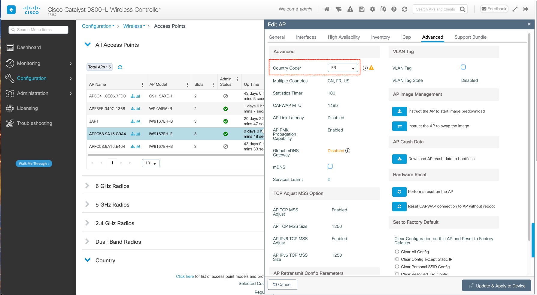
To configure the AP to indoor mode, use the ap name <ap-name > indoor command from wireless LAN controller. This command triggers an AP rebooting. After AP registers to the wireless LAN controller after rebooting, you need to assign corresponding country code to the AP. When indoor deployment is enabled, 5G radio supports channels 36, 40, 44, 48, 52, 56, 60, 64, 100, 104, 108, 112, 116, 120, 124, 128, 132, 136, 140.


Note


To disable indoor deployment, use the ap name <ap-name > no indoor command.


Note


Channel list extends from U-NII-2c to U-NII-1, U-NII-2a, U-NII-2c (channel 144 is excluded).


802.11ax 1600ns and 3200ns Guard Interval Support

802.11ac has two Guard Interval (GI) options – long GI (800ns) and short GI (400ns). 802.11ax introduces new guard interval options. It has three types of GI – 800ns, 1600ns, and 3200ns. Longer guard intervals provide improved performance in environments with multi-path and delay spread. It improves link reliability for longer-range outdoor deployments and helps to prevent inter-symbol interference in outdoor environments and therefore improve coverage and performance.

The following table compares 802.11ax to the previous two standards.

Table 1. 802.11ax Guard Interval Comparing With Previous Standards

Capabilities

802.11n

802.11ac

802.11ax

Physical Layer (PHY)

High Throughput (HT)

Very High Throughput (VHT)

High-Efficiency (HE)

Guard Interval

800/400 ns

800/400 ns

800/1600/3200 ns

Configuring 802.11ax Long Guard Interval

HE mode guard intervals should be configured in RF profiles.

Procedure


Step 1

Enters global configuration mode.

Device#configure terminal

Example:


Device#conf t
Enter configuration commands, one per line.  End with CNTL/Z.

Step 2

Configures RF profile and enters RF profile configuration mode

ap dot11  {24ghz |5ghz } rf-profile  <profile-name >

Example:

Device(config)#ap dot11 24ghz rf-profile 24G-RF-profile

Step 3

Configures guard interval for the RF profile.

guard-interval  {GUARD_INTERVAL_1600NS  | GUARD_INTERVAL_3200NS  | GUARD_INTERVAL_400NS  | GUARD_INTERVAL_800NS }

Example:

Device(config-rf-profile)#guard-interval GUARD_INTERVAL_1600NS
  • GUARD_INTERVAL_1600NS: Set 1600 ns guard interval (only in HE mode)

  • GUARD_INTERVAL_3200NS: Set 3200 ns guard interval (only in HE mode)

  • GUARD_INTERVAL_400NS: Set 400 ns guard interval (HT VHT mode)

  • GUARD_INTERVAL_800NS: Set 800 ns guard interval

Note


Valid guard interval values are 800, 1600, and 3200 ns for HE mode. By default, GI is 800 ns.

Step 4

Exit global configuration mode.

end

Example:

Device(config)#end

Use the following command to verify the configuration on wireless controller:

#show ap rf-profile name Demo-24G-RF-profile detail | inc Guard
Guard Interval        : 1600ns
#show ap rf-profile name Demo-5G-RF-profile detail | inc Guard
Guard Interval        : 3200ns

Example

1. Define GI in RF profile

ap dot11 24ghz rf-profile Demo-24G-RF-profile
shutdown
guard-interval GUARD_INTERVAL_1600NS
no shutdown
ap dot11 5ghz rf-profile Demo-5G-RF-profile
shutdown
guard-interval GUARD_INTERVAL_3200NS
no shutdown

2. Associate RF profile to RF tag

wireless tag rf Demo-Guard-Interval-RF-tag
24ghz-rf-policy Demo-24G-RF-profile
5ghz-rf-policy Demo-5G-RF-profile

3. Associate RF tag to AP

ap fc58.9a15.c83c
rf-tag Demo-Guard-Interval-RF-tag

GNSS Support

From Cisco IOS XE Dublin 17.11.1, GNSS is supported on IW9167EH. The AP tracks GPS information for devices deployed in the outdoor environment and sends the GNSS information to the wireless controller.

Use the following command to display the GNSS information on the AP:

ap# show gnss info.

Use the following commands to display the GPS location of the AP:

controller# show ap geolocation summary

controller# show ap name <Cisco AP> geolocation detail

RAP Ethernet Daisy Chain

The RAP Ethernet Daisy Chain feature enhances the existing Ethernet bridging functionality. It forces the bridge AP to stick to the Ethernet link, and block the selecting of wireless link for uplink backhaul. Even the Ethernet link failure happens, the access point will never select a parent over wireless backhaul.

The following figure shows an example of RAP Ethernet Daisy Chain topology. Standalone DC power source is provided to each RAP.

Figure 1. RAP Ethernet Daisy Chain Topology
Table 2. Port Mapping

Panel Label

SW Interface

mGig POE-IN port

wired 0

SFP

wired 1


Note


The supported SFP module for this feature is the 1000BASE-T rugged SFP (Cisco PID: GLC-T-RGD).


Follow these guidelines when you configure this feature:

  • All APs in daisy chain is operating in mesh bridge mode or Flex+Bridge mode with Root AP role. The PoE-IN (wired0) and SFP (wired1) port can be used as uplink port and the PoE-IN (wired0) port has the higher priority than SFP (wired1).

  • VLAN transparency should be disabled on all daisy-chained RAPs.

  • To enable VLAN support on each root AP:

    • For bridge mode APs, use the ap name name-of-rap mesh vlan-trunking [native] vlan-id command to configure a trunk VLAN on the corresponding RAP.

    • For Flex+Bridge APs, you must configure the native VLAN ID under the corresponding flex profile.

The RAP Ethernet Daisy Chain feature is already supported on Cisco IOS XE Cupertino 17.9.3, while it has the following limitations:

  • Primary ethernet port (mGig port) must be used as uplink. In this case, SFP port to SFP port connection is not supported, which impacts network throughput (no 2.5Gbps or 5Gbps copper SFP available when SFP connect to mGig port).

  • Reuse an existing command persistant-ssid to enable the RAP Ethernet Daisy Chain feature, which is misleading.

In Cisco IOS XE Dublin 17.11.1, the RAP Ethernet Daisy Chain feature is enhanced to support the following functions:

  • Wireless Spanning Tree Protocol (WSTP) hello is enabled to support auto root port detection, so that RAP can use any port as its uplink. See the following topology.

    Figure 2. RAP Ethernet Daisy Chain With WSTP Topology
  • A separate and dedicated command rap-eth-daisychain is introduced to enable the feature.

WSTP Overview

Wireless LAN spanning tree protocol (WSTP) organizes a Cisco mesh network into a loop-free spanning tree topology. It quickly configure a mesh network into a stable, loop-free, optimal spanning tree topology, where an optimal topology provides least-cost paths to the primary Ethernet LAN. WSTP Hello messages are used to build the WSTP topology.

The WSTP super root is a single RAP that is elected as the highest level “super” root for the entire WSTP spanning tree. The super root is directly attached to the primary LAN. The super root transmits zero-cost WSTP SR Hello messages on its Ethernet root port to advertise the primary LAN to RAPs.

Comparison with Previous Release

The following table compares the daisy chain features in current release and prior to 17.11:

Prior to Release 17.11.1

Release 17.11.1

Topology

Fixed topology

RAP must use its mGig port as uplink in daisy chain topology

Flexible topology

RAP can use either mGig port or SFP port as uplink in daisy chain topology by enabling WSTP on AP

Feature enablement

Persistant-ssid in AP profile

1

rap-eth-daisychain in Mesh profile

Ring Topology

Not supported 2

Not supported

1 Persistant-ssid is still supported in 17.11, so that daisy chain function will not be impacted after upgrading from previous release to 17.11 with old configuration. But Persistant-ssid is not recommended in 17.11, and the new rap-eth-daisychain command is recommended.
2 Supported only on IW6300 access point, by enabling daisychain-stp-redundancy. For more information, see the RAP Ethernet Daisy Chain Redundancy for STP Ring Topology section in Cisco Catalyst IW6300 Heavy Duty Series and 6300 Series Embedded Services Access Point Software Configuration Guide.

RAP Ethernet Daisy Chain Configuration

This section provides procedures for the RAP Ethernet daisy chain configuration.

Preconfiguring RAP Ethernet Daisy Chain Before Field Deployment

This section provides the preconfiguration that you should complete in lab before you set up in field deployment.

Procedure

Step 1

Unpack, connect, and power on the AP.

Step 2

Join each AP to controller with mGig port. See the following figure for details.

Step 3

Configure AP to bridge mode and configure AP role to Root AP.

For detailed configuration procedures, see https://www.cisco.com/c/en/us/td/docs/wireless/controller/9800/17-11/config-guide/b_wl_17_eleven_cg/m_mesh_ewlc.html#task_pnb_bwy_mlb.

Step 4

Configuring RAP Ethernet Daisy Chain.

  1. Create mesh profile and enable the Rap Ethernet Daisy chain feature.

    See Enabling RAP Ethernet Daisy Chain.

  2. Attach the profile to all the RAP.

  3. Configure one AP as Super Root which should be the first hop to the wireless controller.

    See Configuring Super Root.

  4. Configure primary Ethernet port on the Super Root AP if you use SFP port as uplink.

    See Configuring Primary Ethernet Port.

Step 5

Enable Ethernet Bridging and Configure Ethernet port.

See Configuring Ethernet Bridging and Ethernet Port.

  1. Enable Ethernet Bridging.

  2. Ethernet port configuration on both Port 0 and Port 1, including port mode and vlan. It is recommended to configure port to trunk mode.

Step 6

Verify the behavior in daisy chain topology.

  1. Connecting the RAP via wired port one by one.

    Note


    The RAP which is the first hop from wireless controller should be configured as Super Root, as shown in the above figure.

  2. Make sure that RAP of each hop can join the controller.

Note


In field deployment, just repeat Step 6 of this procedure. Make sure you configure the first hop as Super Root.


Enabling RAP Ethernet Daisy Chain

To enable RAP Ethernet Daisy Chain feature, use the rap-eth-daisychain command, or configure from GUI.

The following example shows enabling the feature from CLI:

#configure terminal
(config)#wireless profile mesh default-mesh-profile
(config-wireless-mesh-profile)#ethernet-bridging
(config-wireless-mesh-profile)#rap-ethernet-daisychain

The following figure shows enabling the feature from GUI:

To verify the configuration, use the show wireless profile mesh detailed command or show wireless mesh ethernet daisy-chain summary command from wireless controller, as shown in the following examples:

#show wireless profile mesh detailed <profile name>
…
RAP ethernet daisychain       : ENABLED
#show wireless mesh ethernet daisy-chain summary
AP Name      BVI MAC        BGN        Backhaul          Ethernet      STP Red        Super Root
----------------------------------------------------------------------------------------------------
APxxxxxx     xxxxxxx       xxxxx       Ethernet0          Up Up          NA            Enabled

Or use the show mesh config command on AP, as shown in the following example:

#show mesh config
…
RAP Ethernet Daisy Chain: Enabled
  Daisy Chain Root: Disabled

Configuring Super Root

The first RAP which connects to the upstream switch should be configured as super root, which means it’s the source of all WSTP hello. Other RAPs only start hello after receiving a hello.

You can configure the super root from wireless controller or from AP.

  • From wireless controller, use the ap name <name> [no] mesh rap-eth-daisychain super-root command to configure a super root.

    To verify the configuration, use the following command:

    #show ap name <name> config general
    …
    RAP ethernet daisychain                 : Enabled
    Super Root                              : Enabled
    
  • On AP, use the capwap ap mesh wstp super-root command to configure a super root.

    To verify the configuration, use the following command:

    #show mesh config
    …
    RAP Ethernet Daisy Chain: Enabled
      Daisy Chain Root: Enabled
    

Configuring Primary Ethernet Port

Super root must use its primary Ethernet port to connect to upstream switch. For IW9167EH, the default primary Ethernet port is Ethernet port 0. To manually configure the primary Ethernet port, use the ap name <name> mesh backhaul ethernet <0/1> command from wireless controller.

To verify the configuration, use the following command from wireless controller:

#show ap name <name> config general
…
AP Primary Ethernet port                        : 1
RAP ethernet daisychain                         : Enabled
Super Root                                      : Disabled

Or use the following commands on AP:

#show mesh config
…
RAP Ethernet Daisy Chain: Enabled
  Daisy Chain Root: Enabled
AP Primary ethernet backhaul interface: 1

#show mesh adjacency parent
AdjInfo: Wired Backhaul: 1 [xx:xx:xx:xx:xx:xx]

Configuring Ethernet Bridging and Ethernet Port

Configuring Ethernet Bridging (CLI)

The Ethernet port on the MAPs are disabled by default. It can be enabled only by configuring Ethernet bridging on the Root AP and the other respective MAPs. Follow these steps to enable Ethernet bridging on the AP.

Procedure

Step 1

Enters global configuration mode.

Device#configure terminal

Step 2

Creates a mesh profile.

wireless profile mesh  profile-name 
Example:
(config)#wireless profile mesh rap-eth-daisy

Step 3

ethernet-bridging

Example:
(config-wireless-mesh-profile)#ethernet-bridging

Connects remote wired networks to each other.

Step 4

Disables VLAN transparency to ensure that the bridge is VLAN aware.

no ethernet-vlan-transparent 
Example:
(config-wireless-mesh-profile)#no ethernet-vlan-transparent

Step 5

Exit global configuration mode.

end

Example:

(config-wireless-mesh-profile)#end

Example

Use the following command to verify the configuration:

#show wireless profile mesh detailed rap-eth-daisy

Mesh Profile Name           : rap-eth-daisy
--------------------------------------
Description                 :
Bridge Group Name           : unconfigured
Strict match BGN            : DISABLED
Amsdu                       : ENABLED
Background Scan             : DISABLED
Channel Change Notification : DISABLED
Backhaul client access      : DISABLED
Ethernet Bridging           : ENABLED
Ethernet Vlan Transparent   : DISABLED
Daisy Chain SP Redundancy   : DISABLED
Full Sector DFS             : ENABLED
Configuring Ethernet Bridging (GUI)

Follow these steps to configure Ethernet Bridging from wireless controller GUI:

Procedure

Step 1

Choose Configuration > Wireless > Mesh > Profiles

Step 2

Click Add.

Step 3

In General tab, enter the Name of the mesh profile.

Step 4

In Advanced tab, uncheck the VLAN Transparent check box to disable VLAN transparency.

Step 5

In Advanced tab, check the Ethernet Bridging check box.

Step 6

Click Apply to Device.


Configuring Ethernet Port (CLI)

RAP Ethernet secondary port supports Access mode and Trunk mode. Follow these steps to configure Ethernet port mode.

  • Use the following command to configure access mode.

    #ap name ap-name mesh ethernet 1 mode access Vlan-ID

  • Use the following commands to configure trunk mode. VLAN support must be enabled in advance, and VLAN transparent should be disabled in your mesh profile.

    • Configure a trunk VLAN on the corresponding RAP.

      #ap name ap-name mesh vlan-trunking native Vlan-ID

    • Configure the native VLAN for the trunk port.

      #ap name ap-name mesh ethernet 1 mode trunk vlan native Vlan-ID

    • Configure the allowed VLANs for the trunk port. Permits VLAN filtering on an ethernet port of any Mesh or Root Access Point. Active only when VLAN transparency is disabled in the mesh profile.

      #ap name ap-name mesh ethernet 1 mode trunk allowed Vlan-ID

Configuring Ethernet Port (GUI)

Follow these steps to configure Ethernet port from wireless controller GUI:

Procedure

Step 1

Choose Configuration > Wireless > Access Points.

The All Access Points section, which lists all the configured APs in the network, is displayed with their corresponding details.

Step 2

Click the configured mesh AP.

The Edit AP window is displayed.

Step 3

Choose the Mesh tab.

Step 4

In the Ethernet Port Configuration section, from the Port drop-down list, choose the port to configure.

Step 5

From the Mode drop-down list, choose access mode or trunk mode.

Step 6

In the Native VLAN ID field, enter the native VLAN for the trunk port.

Step 7

Click Update and Apply to Device.


Show and Debug Command

  • Use the following command to debug WTP:

    AP#debug mesh wstp
      error    Mesh wstp error debugs
      events   Mesh wstp events debugs
      packets  Mesh wstp packet debugs
  • Use the following command to display the WSTP statistics:

    AP#show mesh stats
    WSTP stats:
    Attach-Cnt Hello-TX Hello-Rx TCN-TX TCN-RX SR-Chg-Cnt ST-Roam-Cnt
             0       58       58      0      0          0           0