- DNP3 Serial (Southbound) to DNP3 IP (Northbound) Translation Use Case
- DNP3 IP (Southbound) to Modbus TCP (Northbound) Translation Use Case
- Southbound DNP3 IP TMW Configuration
- Northbound Modbus TCP TMW Configuration
- Virtual RTU ES200
- Modbus TCP (Control Center) to DNP3 IP (IED) Register Mapping
- Reading DNP3 Southbound Data from Northbound Modbus Control Center
- Unsolicited Reporting
- Control Command
- Present Analog Output Block Register 2 Value at Southbound
- Present HoldingRegister 2 Value at Northbound
- Changing Holding Register 2 Value
- DNP3 IP (Southbound) to T104 (Northbound) Translation Use Case
- Reading DNP3 Southbound Data from Northbound T104 Control Center
- Northbound Control Center Single Point Information 3 and 4
- Unsolicited Reporting
- Dynamically Updated Northbound Values
- Control Command
- Present Analog Output Block Register 2 Value at Southbound
- Present Normalized Commands Register 2 Value at Northbound
- Changing Normalized Commands Register 2 Value
- Changes Reflecting in Southbound Binary Output Statuses Register 2
- Unsolicited Reporting in T104 Control Center
- IEC 61850-MMS (Southbound) to DNP3 IP (Northbound) Translation Use Case
- IEC 61850-MMS (Southbound) to T104 (Northbound) Translation Use Case
Connected Utilities Virtual RTU Implementation Guide
This implementation guide includes the following major sections:
|
|
|
|---|---|
|
|
|
|
|
|
|
|
|
|
|
|
|
|
|
|
|
|
|
|
|
Introduction
This chapter includes the following topics
Overview
This document captures implementation details of the Virtual Remote Terminal Unit (Virtual RTU) application on the Cisco IR8x9 Integrated Services Router and Cisco IR1101 Integrated Services Router Rugged, which can be deployed as a secondary substation or as a distribution automation gateway. The Virtual RTU application's lifecycle is managed using the Cisco Internet of Things (IoT) Field Network Director (FND). Eximprod, which provides our Supervisory Control and Data Acquisition (SCADA), is a Cisco Solution partner. The ES200 is Eximprod's Virtual RTU application. When we use Virtual RTU terminology in this document, we are referring to the only software we have validated—the ES200.
Use cases that have been addressed in this guide are SCADA visibility and monitoring of secondary substation intelligent end devices (IEDs), SCADA protocol translations, and life cycle management of Virtual RTU. Later, this document will be expanded to include distribution automation use cases such as Fault Location Identification and Service Restoration (FLISR) and Volt/VAR. Finally, this information will be integrated into the Secondary Substation CVD planned efforts that are under the umbrella of the Cisco Field Area Network (FAN) Solution.
Protocol translation supported matrix support by Virtual RTU is shown in Table 1.
Virtual RTU ES200 will work as the Modbus/DNP3/IEC 61850-MMS master to Southbound SCADA clients in the secondary substation (or distribution feeder controller) and, in turn, can act as the Modbus/DNP3 Slave/T104 to Northbound Distribution System Operator (DSO) SCADA systems. Southbound of Virtual RTU can be Ethernet or RS232 and Northbound is Ethernet TCP/IP communication.
For more details about Virtual RTU, please refer to the following:
■![]() http://www.epg.ro/wp-content/uploads/2017/09/ES200-Datasheet-public.pdf
http://www.epg.ro/wp-content/uploads/2017/09/ES200-Datasheet-public.pdf
Audience and Scope
The audience of this guide comprises, but is not limited to, system architects, network/compute/system engineers, field consultants, Cisco Advanced Services specialists, and customers.
This guide describes how to deploy edge compute applications. Readers should be familiar with networking protocols, Network Address Translation (NAT), and SCADA protocols, and have exposure to Edge computing and Field Area Network Solution Architecture.
Implementation Workflow
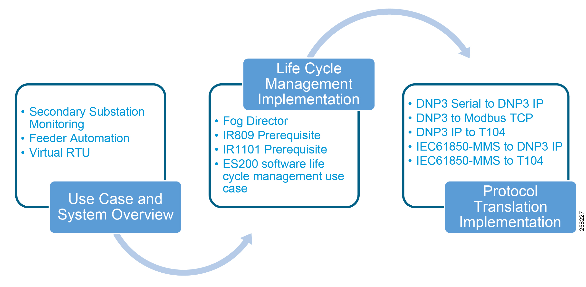
Figure 1 provides the high-level implementation flow for deploying Virtual RTU use cases.
Figure 1 Virtual RTU Implementation Workflow
System Use Cases
This chapter, which describes secondary substation monitoring, distribution automation, and SCADA Protocol translation use cases and how the use of Virtual RTU will benefit DSOs, includes the following major topics:
■![]() Secondary Substation Monitoring
Secondary Substation Monitoring
■![]() Distribution (Feeder) Automation
Distribution (Feeder) Automation
■![]() Virtual RTU and Protocol Translation
Virtual RTU and Protocol Translation
Secondary Substation Monitoring
Secondary substations are used to step down the power voltage from medium (1kv - 40 kV) to low voltage (110/220 V). A secondary substation hosts a transformer and a number of devices called intelligent end devices (IEDs) such as circuit breakers, voltage sensors, reclosers, and surge protectors. IEDs are currently managed by a centralized application located at the DSO's Control Center called the SCADA. IEDs are connected to RTUs in the secondary substation. DSO SCADA software will be communicated to Remote RTUs to poll for the current register value associated with IEDs or to issue control command.
A secondary substation may also host a smart meter concentrator that collects data from the meters and performs local processing to report information back to the Control Center. Information and Communication Technology networks play a key role in connecting secondary substation RTUs to centralized SCADA systems.

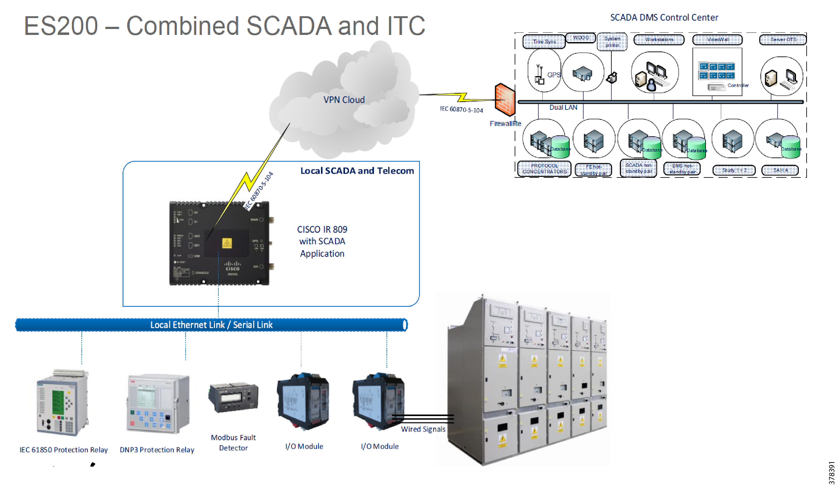
In Figure 2, two different physical components are depicted: RTUs and the substation router. In the Virtual RTU use case, we are combining two different functionalities into one physical component: the Virtual RTU Eximprod ES200 application, which will be hosted on the Cisco IR809/IR1101 secondary substation router as an edge compute application container.
Distribution (Feeder) Automation
Distribution Automation (DA) refers to the monitoring and control of devices located out on the feeders themselves such as line reclosers, load break switches, sectionalizers, capacitor banks, and line regulators.
Distribution Automation is the overlay network deployed in parallel to the Distribution Feeder to enable the two-way communication between controllers used in the Distribution Feeder and Intelligence Application that is residing in the Utility Control Center or Substation for improving grid reliability, availability, and control.
Figure 3 depicts a typical DA system.
Figure 3 Distribution Automation

Two important use cases for Distribution Automation are:
DA Volt/VAR Regulation and FLISR use cases will be deployed globally around the world. Cisco DA gateways such as Cisco IR807, IR807, and IR1101 will be deployed 1:1 with DA controllers, including the recloser controller and capacitor bank controllers.
FLISR Use Case
Fault Location Isolation and Service Restoration (FLISR) is the process for dealing with fault conditions on the electrical grid. The following occurs as part of this process:
1.![]() Detects (and locates) faults
Detects (and locates) faults
2.![]() Isolates the faults to the smallest segment of the grid possible
Isolates the faults to the smallest segment of the grid possible
3.![]() Restores as much service as possible while the fault is isolated
Restores as much service as possible while the fault is isolated
FLISR includes automatic sectionalizing and restoration and automatic circuit reconfiguration. These applications accomplish DA operations by coordinating operation of field devices, software, and dedicated communication networks to automatically determine the location of a fault, and then rapidly reconfigure the flow of electricity so that some or all of the customers can avoid experiencing outages.
Because FLISR operations rely on rerouting power, they typically require feeder configurations that contain multiple paths to single or multiple other substations. This creates redundancies in power supply for customers located downstream or upstream of a downed power line, fault, or other grid disturbance.
■![]() Consumers experience minimal outage.
Consumers experience minimal outage.
■![]() Utilities improve their System Average Interruption Duration Index (SAIDI) and System Average Interruption Frequency Index (SAIFI) numbers and avoid financial penalties that could be levied by the regulator.
Utilities improve their System Average Interruption Duration Index (SAIDI) and System Average Interruption Frequency Index (SAIFI) numbers and avoid financial penalties that could be levied by the regulator.
Volt/VAR Use Case
This use case address automating dynamic and efficient delivery of power. Utilities look at achieving large savings by enhancing the efficiency of their power distribution infrastructure; in other words, improving the effectiveness of the flow of electricity. In order to evaluate the process, it is important to review the differences between what is called real power and reactive power.
Real power is what we use to run all lights, devices, and production lines. It is the power that does the work. Reactive power does not contribute anything to doing work, but it does cause conductors to heat up and takes up a certain amount of space in the wires. The more reactive power flowing on a line, the less room exists for real power and the less efficient is the distribution system.
Today, in order to eliminate or at least minimize reactive power flows, utilities have deployed on their local distribution systems devices such as capacitor banks or special transformers that are typically located at substations or on a feeder. These devices work to keep reactive power flows down, making the full capacity of the conductor available for the real power. This process is known as Volt/VAR regulation or control.
■![]() VAR Compensation—Improves efficiency of energy supply by ensuring voltage and current are in phase when supplied to the customer.
VAR Compensation—Improves efficiency of energy supply by ensuring voltage and current are in phase when supplied to the customer.
■![]() Conservation Voltage Regulation—During peak load, ensures the minimum required voltage level is supplied to the customer.
Conservation Voltage Regulation—During peak load, ensures the minimum required voltage level is supplied to the customer.
Most existing deployments have a centralized approach of controlling DA controllers from the DSO Control Center using SCADA applications. Utilities are moving towards distributed control approach where decisions can be made more quickly at the distribution feeder level by running customer business logic at the DA Gateway level. Cisco IR809 plays a perfect role for these deployment scenarios since we can host Virtual RTU software that allows utilities to implement customer business logic according to their requirements and needs.
Virtual RTU and Protocol Translation
Virtual RTU
Eximprod ES200 over the Cisco IR8x9 and IR1101 series, as shown in Figure 4, is a fourth-generation (Internet of Things or IoT) SCADA RTU gateway for control, measurement, and supervision in power distribution systems. ES200 is designed to efficiently operate secondary distribution substations, feeders, and electrical substations using modern and secure communication and automation standards.
Virtual RTU can integrate existing multi-vendor equipment and runs SCADA software without dedicated hardware. Since it is software based, RTU time to deploy and add new features can be done more quickly than with legacy hardware RTU. Security features and customer business logic can be implemented based on customer requirements.
SCADA Protocol Translation
SCADA protocol translations are needed when DSO is running different (or advance) SCADA protocols as compared to field devices in secondary substation IEDs or distribution feeder controllers. Another scenario for protocol translations is when the last mile (such as between DA gateway and field devices) is connected via a legacy RS232 connection, but the DSO connections are migrated to Ethernet TCP/IP.
Figure 5 depicts a SCADA protocol translation scenario where the DSO SCADA uses the Modbus TCP Protocol, but sensors and actuators in the secondary substation are using Distributed Network Protocol 3 (DNP3).
Figure 5 SCADA Protocol Translation using Virtual RTU

The SCADA protocol translation matrix supported by Virtual RTU is explained in Introduction. The various SCADA protocol translation implementations are explained in SCADA Protocol Translation Use Case using Virtual RTU.
Note: The protocol translations are not related to the implementation of Cisco IOS.
IEC 61850 SCADA Protocol Translation
This translation from IEC 61850 MMS to T104 or DNP3 and vice versa is achieved by using Virtual RTU running on the edge gateway.
Figure 6 IEC 61850 SCADA Protocol of IEC 61850 MMS

1.![]() The Control Relay Output Blocks (CROB) Control command on the DNP3 Binary Output register is initiated from the SCADA Control Center to the ES200 application
The Control Relay Output Blocks (CROB) Control command on the DNP3 Binary Output register is initiated from the SCADA Control Center to the ES200 application
2.![]() The ES200 application translates the DNP3 Binary Output point to the IEC 61850 Binary point and forwards it to the IED Oper.OperVal register where actual control is required.
The ES200 application translates the DNP3 Binary Output point to the IEC 61850 Binary point and forwards it to the IED Oper.OperVal register where actual control is required.
3.![]() The Oper.OperVal updates the status to the Pos.Oper.ctVal register.
The Oper.OperVal updates the status to the Pos.Oper.ctVal register.
4.![]() IEC 61850 then updates the ES200 IEC 61850 client about this updated value. The ES200 internally translates the Analog Input to the DNP3 Double Input point.
IEC 61850 then updates the ES200 IEC 61850 client about this updated value. The ES200 internally translates the Analog Input to the DNP3 Double Input point.
5.![]() The unsolicited reporting feature of DNP3 would immediately report the updated value to the SCADA Control Center.
The unsolicited reporting feature of DNP3 would immediately report the updated value to the SCADA Control Center.
System Overview and Components
The solution is comprised of the Utilities Distributed System Operator Control Center block (the green cloud in the solution topology in Figure 7), the Wide Area Network (WAN) block, and the Secondary Substation block.
The Cisco IoT FND and SCADA software are installed on the DSO. The Cisco ASR 1000 series router is acting as the Headend Router (HER/Control Center router), which terminates the encrypted tunnels from different secondary substation routers. Encrypted tunnels carry SCADA traffic. HER decrypts and routes SCADA traffic to DSO SCADA systems. The Cisco IoT FND is used for lifecycle management of the Virtual RTU application. For more information about Cisco ASR 1000, please refer to Cisco ASR 1000 Series Aggregation Services Routers at the following URL:
■![]() https://www.cisco.com/c/en/us/products/routers/asr-1000-series-aggregation-services-routers/index.html
https://www.cisco.com/c/en/us/products/routers/asr-1000-series-aggregation-services-routers/index.html
Backhaul to the DSO Control Center can be Ethernet or cellular. Backhaul can be fully secured through Cisco's VPN technologies such as Cisco Dynamic Multipoint Virtual Private Network (DMVPN) and Cisco FlexVPN.
Figure 7 Virtual RTU Solution Topology

In the topology in Figure 7, the Virtual RTU ES200 software is installed on the Cisco IR809, which is acting as a secondary substation router. Sensors and actuators are simulated using a PC running the Triangle MicroWorks (TMW) Protocol Test Harness application and Distributed Test Manager (DTM). A PC running TMW is connected to the Cisco IR809/IR1101 using Ethernet and serial (RS232) interfaces. This guide will be later enhanced to include Distribution Automation use cases. Table 3 lists the hardware and software combination used in solution validation.
| ■ |
|
| ■ |
|
■ ■ |
|
Distributed Test Manager (DSO Center SCADA and IED simulators) |
|
Note: Contact Eximprod's team at https://www.epg.ro/en/contact/, to download Eximprod's Virtual RTU software and to generated to license for Eximprod's license for edge devices.
Lifecycle Management Implementation
This chapter includes the following major topics:
Cisco IR809 Prerequisites
Image and Upgrade Details
Note: Cisco IR809 should be running with a minimum 15.6 version to support the Docker container application. For details, please refer to the release notes at the following URL:
■![]() https://www.cisco.com/c/en/us/td/docs/routers/access/800/829/15-6-3M2-Release-Notes.html
https://www.cisco.com/c/en/us/td/docs/routers/access/800/829/15-6-3M2-Release-Notes.html
It is recommended to install the latest image version from the https://software.cisco.com/download/home website.
1.![]() Download and copy the Cisco IR809 bundle image to the Cisco IR809 flash drive.
Download and copy the Cisco IR809 bundle image to the Cisco IR809 flash drive.
3.![]() Upgrade guest OS using the following command. After upgrading, restart the router.
Upgrade guest OS using the following command. After upgrading, restart the router.
4.![]() Verify the upgrade using the following command:
Verify the upgrade using the following command:
5.![]() Make sure you have the correct licenses:
Make sure you have the correct licenses:
6.![]() WAN interface configuration for Northbound communication towards DSO Control Center:
WAN interface configuration for Northbound communication towards DSO Control Center:
Note: If Cellular is used as an underlay WAN interface, ignore the GigabitEthernet interface configuration and configure the Cellular interface. For details on the Cellular configuration, refer to the Distribution Automation - Secondary Substation (Design Guide) at the following URL:
–![]() https://www.cisco.com/c/en/us/td/docs/solutions/Verticals/Distributed-Automation/Secondary-Substation/DG/DA-SS-DG.html
https://www.cisco.com/c/en/us/td/docs/solutions/Verticals/Distributed-Automation/Secondary-Substation/DG/DA-SS-DG.html
9.![]() Serial Interface connecting to serial devices in the substation (Southbound):
Serial Interface connecting to serial devices in the substation (Southbound):
The command encapsulation relay-line is used to relay the serial traffic to IOx application.
Note: Validation was done using RS232 based on the configuration above. Async0 can work in RS232 DCE mode and RS485 DCE Mode. Async1 can only work in RS232 DTE mode.
10.![]() Serial relay configuration:
Serial relay configuration:
Note: Async0 and Async1 reserve line 1/5 and 1/6, respectively, to relay serial data to the corresponding GuestOS /dev/ttyS1 and /dev/ttyS2.
Serial Relay Line allows Serial ports to pass traffic directly to the Guest OS:
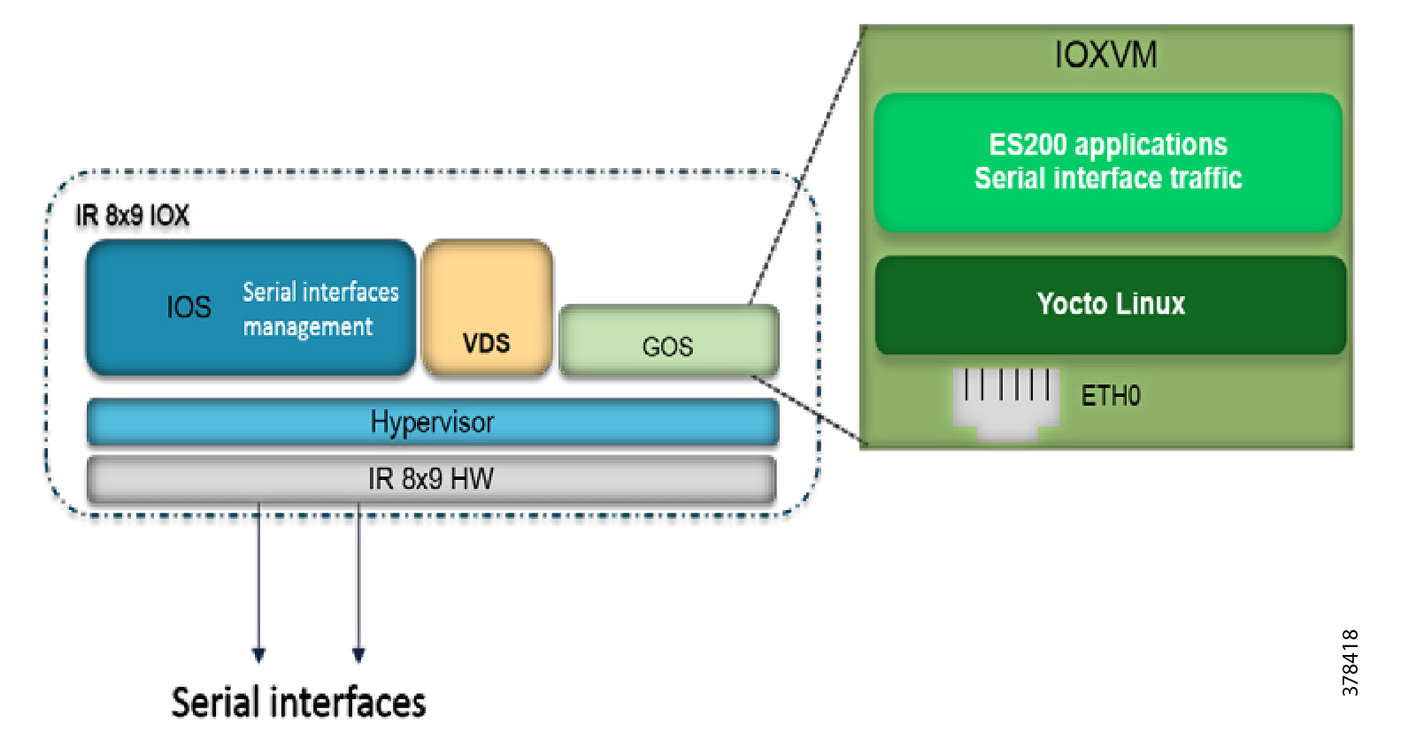
Note: Propagation options allow the baudrate, databits, stopbits, and parity propagation from Guest OS. If propagation is present, the control parameters will be passed from the Guest OS to the IOS physical port.
Figure 8 Serial Interface: IR8x9 IOx—IOxVM
Static NAT or Interface overload needs to be configured:
In this example, 192.168.1.250 is the Guest OS IP address. We are doing Static NAT to convert into a public routable IP address. Fog Director uses this public IP address to identify the device.
To preserve the public IP address interface, overload can be used.
A sample configuration is shown below:
Figure 9 NAT: IOxVM Network Interfaces
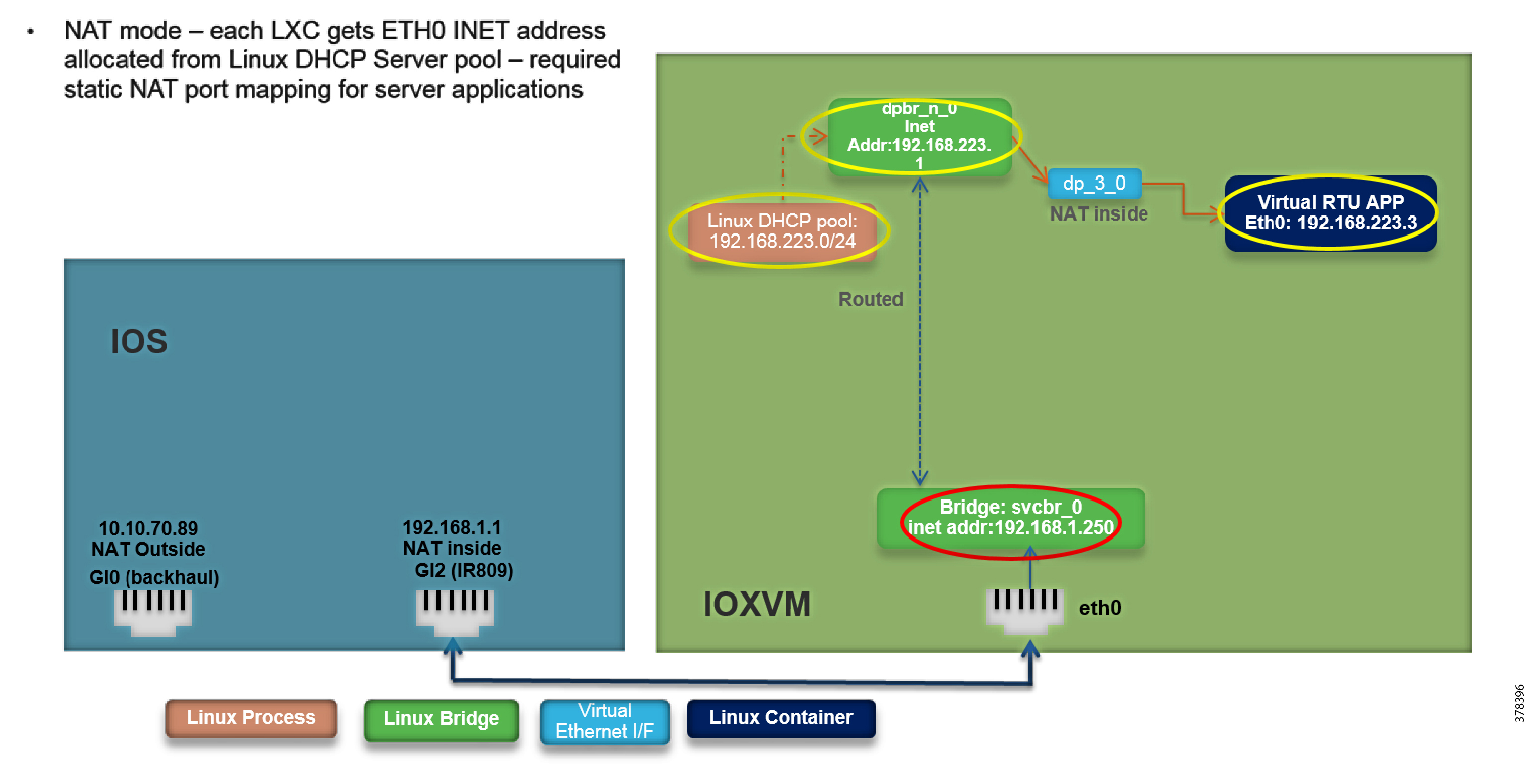
The app obtains the IP address from a DHCP server within iOx. iOx then assigns the outside port numbers if the application is deployed in NAT mode.
iOx should be configured in NAT mode for docker container applications.
The port required by application should be specified in the YAML file. For the ES200 Virtual RTU application, the Port 1731 needs to opened up.
13.![]() LTE Backhaul and Network Layer Encryption:
LTE Backhaul and Network Layer Encryption:
Please refer to the Cisco IR800 Integrated Services Router Software Configuration Guide at the following URL:
–![]() https://www.cisco.com/c/en/us/td/docs/routers/access/800/829/software/configuration/guide/IR800config.pdf
https://www.cisco.com/c/en/us/td/docs/routers/access/800/829/software/configuration/guide/IR800config.pdf
Cisco IR1101 Prerequisites
IR1101 Virtual Port Group Mapping for IOx
The VirtualPortGroup interface connects the application hosting network to the IOS routing domain. The Layer 3 interface of the application receives routed traffic from IOS. The VirtualPortGroup interface connects through the SVC Bridge to the container/application interface.
Figure 10 helps to understand the relationship between the VirtualPortGroup and other interfaces, since it is different from IR8x9 routers.
Note: IR1101 uses VirtualPortGroup to communicate with Edge Compute application, instead of Gi2 interface as in IR8x9 routers.
Figure 10 VirtualPortGroup Mapping

Image and Upgrade Details
Note: Cisco IR1101 should be running with a minimum 16.12.01 version to support the IOx application. For details, please refer to the Release Notes for Cisco IR1101 Industrial Integrated Services Router, Cisco IOS XE Gibraltar 16.12.x at the following URL:
■![]() https://www.cisco.com/c/en/us/td/docs/routers/access/1101/release/IR1101-release-notes-16-12-1.html
https://www.cisco.com/c/en/us/td/docs/routers/access/1101/release/IR1101-release-notes-16-12-1.html
1.![]() Download and copy the Cisco IR1101 IOS-XE image to the Cisco IR1101 flash drive.
Download and copy the Cisco IR1101 IOS-XE image to the Cisco IR1101 flash drive.
2.![]() Enter global configuration:
Enter global configuration:
3.![]() Delete all entries in the bootable image list:
Delete all entries in the bootable image list:
4.![]() Configure boot system variable:
Configure boot system variable:
7.![]() After the device restarted with the latest image, verify the IOx service status using the following command:
After the device restarted with the latest image, verify the IOx service status using the following command:
Verify that CAF and IOxman services are in running state.
8.![]() Make sure you have the correct licenses:
Make sure you have the correct licenses:
9.![]() WAN interface configuration for Northbound communication towards the DSO Control Center:
WAN interface configuration for Northbound communication towards the DSO Control Center:
11.![]() Serial Interface connecting to serial devices in the substation (Southbound):
Serial Interface connecting to serial devices in the substation (Southbound):
12.![]() Serial relay configuration:
Serial relay configuration:
Note: Validation was done using RS232 based on the configuration above on interface Async0. On IR1101, line 0/2/0 is the same as line 50.
Cisco Fog Director
Note: Fog Director features are integrated into the latest Cisco IOT FND. For the purpose of validation, we have used Fog Director for IR8x9 and IOx Local Manager WebUI for IR1101. The Cisco IOT FND version was not available during the implementation phase of this document.
For more details on Cisco IOT FND, refer to the following URL:
■![]() https://www.cisco.com/c/en/us/products/cloud-systems-management/iot-field-network-director/index.html?dtid=osscdc000283
https://www.cisco.com/c/en/us/products/cloud-systems-management/iot-field-network-director/index.html?dtid=osscdc000283
How to Install Cisco Fog Director
To install the Cisco Fog Director, please refer to the Cisco Fog Director Reference Guide, Release 1.8 at the following URL:
■![]() https://www.cisco.com/c/en/us/td/docs/routers/access/800/software/guides/iox/fog-director/reference-guide/1-8/fog_director_ref_guide.html
https://www.cisco.com/c/en/us/td/docs/routers/access/800/software/guides/iox/fog-director/reference-guide/1-8/fog_director_ref_guide.html
The recommended version is 1.3 and above.
Figure 11 Cisco Fog Director Version

Adding Cisco IR809 Secondary Substation Router into Fog Director
1.![]() From Devices, click Add, as shown in Figure 12, and then enter the relevant details for devices such as IP address and port:
From Devices, click Add, as shown in Figure 12, and then enter the relevant details for devices such as IP address and port:
Figure 12 Adding Cisco IR809 in Fog Director

2.![]() Once the device is added successfully, you can verify the last heard status using the option shown in Figure 13.
Once the device is added successfully, you can verify the last heard status using the option shown in Figure 13.

IOx Application Types
For this document’s purpose, two types of IOx application are used for the two different platform architectures:
■![]() For IR8x9 platform (x86 architecture), Docker style container application is used for validation, and
For IR8x9 platform (x86 architecture), Docker style container application is used for validation, and
■![]() For IR1101 platform (ARM64v8 architecture), LXC/Platform as a service (PaaS) style container application is used for validation. IR1101 is a bit different in comparison with most other IOx platforms as these are mainly x86 based. The IR1101 is based on the ARM64v8 architecture so you cannot deploy containers or IOx packages built for x86 on the platform directly.
For IR1101 platform (ARM64v8 architecture), LXC/Platform as a service (PaaS) style container application is used for validation. IR1101 is a bit different in comparison with most other IOx platforms as these are mainly x86 based. The IR1101 is based on the ARM64v8 architecture so you cannot deploy containers or IOx packages built for x86 on the platform directly.
For information on different styles of container applications, refer to the following URL:
■![]() https://developer.cisco.com/docs/iox/#!application-types/application-types
https://developer.cisco.com/docs/iox/#!application-types/application-types
Adding Docker Container ES200 Application
The Virtual RTU Docker package.yaml will be provided by Eximprod. Refer to the following configuration for a sample file. This file needs to be loaded on your laptop/client machine running the Cisco Fog Director client application.
Edit necessary network ports. For example, specify the Northbound ports needed by the Fog Director and device parameters (such as serial interface parameters). Port 1731 will be used by the Virtual RTU. Port 2401 is be used for Northbound communication from the Virtual RTU to Control Center communication.
Adding a New Application
1.![]() Click Add New App under the App tab in the Fog Director, as shown in Figure 14:
Click Add New App under the App tab in the Fog Director, as shown in Figure 14:

2.![]() Click the Create from Docker image checkbox listed, as shown in Figure 15.
Click the Create from Docker image checkbox listed, as shown in Figure 15.
Note: For applications other than Docker type, click the Upload from my computer checkbox from Figure 14 and jump to Publishing a Newly Added Application. For the purpose of this document:
■![]() Docker style container application is used for IR809 validation
Docker style container application is used for IR809 validation
■![]() Linux Container (LXC) style container application is used for IR1101 validation
Linux Container (LXC) style container application is used for IR1101 validation
For information on different styles of container applications, refer to the following URL:
■![]() https://developer.cisco.com/docs/iox/#!application-types/application-types
https://developer.cisco.com/docs/iox/#!application-types/application-types

Fill in the required credentials in order to download the image from the repository and then choose the application's corresponding valid configuration file (package. yaml).
Click Submit and wait for a successful application download.
Figure 16 Docker Image Details

Publishing a Newly Added Application
After successful application download, the application is ready to be published, as shown in Figure 17:

After successful publication, the application is ready for installation, as shown in Figure 18:
Figure 18 App Ready to Install

Installing a Newly Published App
The application can be installed on devices of interest. As part of the installation process, those devices are chosen and the networking parameters and interfaces of the device are configured, as shown in Figure 19 and Figure 20:

Figure 20 Add Selected Devices

After clicking Add Selected Devices, click Next. Modify the Resource Profile if needed, as shown in Figure 21:

Networking should be set to nat-0, as shown in Figure 22:

By default, Serial Device would point to async1, but you should change it to async0 since the Southbound IED is connected to the async0 serial port, as shown in Figure 23.
Figure 23 Serial Device Details

A successful installation of the application will be reflected on the Cisco Fog Director portal. More details of the application will also be shown on the Cisco Fog Directory portal, as shown in Figure 24:
Figure 24 App Installation Success

ES200 Lifecycle Management
Stopping ES200 Docker Container Application from Fog Director
Click Devices to see the App running status and then click the square Stop App button to stop the application, as shown in Figure 25:

Restarting the ES200 Docker Container Application from the Fog Director
Click Start App to restart the stopped application from the Fog Director, as shown in Figure 26:

Editing Parameters from the Fog Director
Stop the App. Edit App Settings (Network and Serial parameters) and then click Reconfigure Settings, as shown in Figure 27. Then, re-start the App.
Figure 27 Editing App Parameters

Uninstalling ES200 Docker Container Application from the Fog Director
Stop the App. Then click Remove App to remove the App, as shown in Figure 28:

Cisco IOx Local Manager
The application management, IOx administration, and troubleshooting can also be done using the Cisco IOx Local Manager GUI when Fog Director is not available.
Cisco IOx Local Manager is a platform-specific application that is installed on a host system as part of the installation of the Cisco IOx framework on that device. It provides a web-based user interface that you can use to manage, administer, monitor, and troubleshoot apps on the host system, and to perform a variety of related activities.
For more details on IOx Local Manager, on how to configure, access the web GUI, refer to the Cisco IOx Local Manager Reference Guide, Release 1.8 at the following URL:
■![]() https://www.cisco.com/c/en/us/td/docs/routers/access/800/software/guides/iox/lm/reference-guide/1-8/b_iox_lm_ref_guide_1_8/b_iox_lm_ref_guide_1_8_chapter_01.html
https://www.cisco.com/c/en/us/td/docs/routers/access/800/software/guides/iox/lm/reference-guide/1-8/b_iox_lm_ref_guide_1_8/b_iox_lm_ref_guide_1_8_chapter_01.html
On the IR110, the IOx Local Manager is embedded in the IR1101 Web Management. For more details on how to use Local Manager WebUI for application hosting, refer to the IR1101 Software Configuration Guide at the following URL:
■![]() https://www.cisco.com/c/en/us/td/docs/routers/access/1101/software/configuration/guide/b_IR1101config/b_IR1101config_chapter_010001.html
https://www.cisco.com/c/en/us/td/docs/routers/access/1101/software/configuration/guide/b_IR1101config/b_IR1101config_chapter_010001.html
SCADA Protocol Translation Use Case using Virtual RTU
This chapter provides details implementation details for the following SCADA protocol translation scenarios:
■![]() DNP3 Serial (Southbound) to DNP3 IP (Northbound) Translation Use Case
DNP3 Serial (Southbound) to DNP3 IP (Northbound) Translation Use Case
■![]() DNP3 IP (Southbound) to Modbus TCP (Northbound) Translation Use Case
DNP3 IP (Southbound) to Modbus TCP (Northbound) Translation Use Case
■![]() DNP3 IP (Southbound) to T104 (Northbound) Translation Use Case
DNP3 IP (Southbound) to T104 (Northbound) Translation Use Case
■![]() Reading DNP3 Southbound Data from Northbound T104 Control Center
Reading DNP3 Southbound Data from Northbound T104 Control Center
■![]() IEC 61850-MMS (Southbound) to DNP3 IP (Northbound) Translation Use Case
IEC 61850-MMS (Southbound) to DNP3 IP (Northbound) Translation Use Case
■![]() IEC 61850-MMS (Southbound) to T104 (Northbound) Translation Use Case
IEC 61850-MMS (Southbound) to T104 (Northbound) Translation Use Case
For more details on SCADA, please refer to the Cisco 1000 Series Connected Grid Routers SCADA Software Configuration Guide at the following URL:
■![]() https://www.cisco.com/c/en/us/td/docs/routers/connectedgrid/cgr1000/1_0/software/configuration/guide/scada/scada1.pdf
https://www.cisco.com/c/en/us/td/docs/routers/connectedgrid/cgr1000/1_0/software/configuration/guide/scada/scada1.pdf
Virtual RTU acts as a master to Southbound IEDs and, in turn, acts as a slave to the DSO SCADA Master.
DNP3 Serial (Southbound) to DNP3 IP (Northbound) Translation Use Case
DNP3
DNP, which was specifically developed for use in electrical utility SCADA applications, is now the dominant protocol in those systems. It is also gaining popularity in other industries, including oil & gas, water, and waste water. The DNP specification defines a large number of data types. Within each type, multiple variations may be supported. These variations may describe whether the data are sent as 16-bit or 32-bit integral values; 32-bit or 64-bit floating point values; with or without timestamps; and with or without quality indicators (flags).
Reading Data (Inputs)
The DNP3 specification supports multiple methods of reading inputs individually or as a group. For example, multiple types of data can be encapsulated in a single message to improve efficiency. Time stamps and data quality information can also be included.
DNP3 also supports change events. By polling for change events, the master station can reduce overall traffic on the line, as only values that have changed are reported. This is commonly called Report by Exception (RBE). To further improve efficiency, DNP3 also supports unsolicited reporting. With unsolicited reporting, slave devices can send updates as values change, without having to wait for a poll from the Master.
The master station can easily process change event data (polled or unsolicited) because the report includes the data type and variation, point number, value, and (optionally) time stamp and quality indicators.
Control Operations (Output)
DNP3 supports control operations via output object groups (Control Relay Output Blocks or CROBs and Analog Output Blocks). DNP3 output objects are also read/write; reading the output object returns the output stats (that is, the last command that was written). The actual value of the control point can be monitored via a binary or analog input.
DNP3 also supports a variety functions commonly used on control applications, such as pulsed and paired outputs.
Implementation Details
The Cisco IR809 router is connected to an actuator or sensor in the Southbound via Ethernet and uses DNP3 as the SCADA communication protocol. Virtual RTU software does the Northbound translation to DNP3 IP since the Control Center software is running the DNP3 IP SCADA application. The Southbound DNP3 actuator is simulated using the TMW Test Harness application. The Northbound DNP3 IP SCADA software is simulated using the TMW Distributed Test Manager (DTM) application.
Southbound DNP3 TMW Configuration
Channel Configuration
The Southbound serial IED is simulated using TMW software. In this example, as shown in Figure 29 and Figure 30, the serial port COM62 with Baud Rate 19200 is connected to Async0 of Cisco IR809:
Figure 29 DNP3 Channel Configuration

Async0 (line 1) has the same baud rate as the serial RTU simulator and 1/5 serial relay connecting to the Guest OS /dev/ttyS1 where the Eximprod Southbound DNP3 master application is running.
Figure 30 DNP3 Advance Channel Configuration

Make sure Parity is set to None, Port is configured in DTR mode, StopBits is 1, and DataBits is 8.
Session-related Configuration
The DNP3 Southbound serial RTU simulator is configured as slave and the source and destination layers are configured as 1 and 1. The DNP3 Master will be running on ES200. Link layer addresses needs to be communicated to the Eximprod team accordingly; they will configure the Virtual RTU database. See Figure 31:
Figure 31 DNP3 Session Configuration

Northbound DNP3 IP TMW Configuration
DNP3 IP Channel Configuration
The TMW DTM software is configured in the DNP3 IP. Master mode is used to simulate Control Center SCADA software. Port 2401 is used to communicate between the DNP3 master and slave running in ES200. This port needs to be opened in IOx NAT mode, which will be defined in the package.yaml file. See Figure 32:
Figure 32 DNP3 IP Channel Configuration

DNP3 IP Session-related Configuration
Configure the DNP3 IP Link layer address based on Virtual RTU ES200 database settings. See Figure 33:
Figure 33 DNP3 IP Session Configuration

DNP3 IP Advanced Settings
AutoTimeSyncIIN and AutoEnabledUsnol are advanced DNP3 IP settings, which need to be enabled; AutoIntegrityOline and AutoIntegrityRestart settings need to be disabled. Please refer to Figure 34 for details:
Figure 34 DNP3 Advance IP Session Configuration

Integrity Poll Use Case
The DNP3 specification supports multiple methods of reading inputs individually or as a group. An integrity poll returns data from Class 0 (known as static data), along with data from Classes 1, 2, and 3 (which will be event data). This may or may not be everything, depending on how the slave is configured.
The integrity poll retrieves all events (Class 1, 2, and 3) and static (Class 0) data from the device. It is typically sent after device restart, loss of communication, or on a periodic basis to ensure all data is accurate. This integrity poll is executed in our case from the Northbound DTM application depicted in Figure 35 and Figure 36.

Figure 36 Integrity Data Poll Class0123

Click Apply and then click OK to initiate a poll.
Poll results for the Northbound DTM application are shown in Figure 37. Click the Show Point List option under the DNP3 IP Session.

In the poll results on the Northbound simulator that are shown above, we received four register values (0, 1, 2, and 3) of binary inputs. In the Southbound IED simulator, these are mapped to register values (6, 7, 8, and 9).
Virtual RTU does the mapping of these registers, which matches the Southbound TMW application register values. Therefore, we conclude that the integrity poll is successful. See Figure 38:
Figure 38 DNP3 IP Input Registers

For the purposes of this document, we just discussed Binary Input register values for the Integrity poll.
Unsolicited Reporting
DNP3 supports unsolicited reporting, which means slave devices can send updates as values change without having to wait for a poll from the master.
In our earlier Integrity polling case, we observed that Southbound Input Register # 7 is off. Southbound Register #1 is mapped as Register #7 in the Northbound. If we change the state of the Southbound register, the Northbound register state will change automatically.
After checking the state check of Input Register #1 value @ Northbound DTM application; in this case, it is OFF. See Figure 39:
Figure 39 DNP3 IP Input Registers Current Value

Now change the register # 7 value to ON (right click and toggle) on the Southbound application, as shown in Figure 40:
Figure 40 DNP3 Southbound Binary Input Register Toggle

Unsolicited reporting is observed on the Northbound application for Input register value #1.The current value is ON, as shown in Figure 41:
Figure 41 DNP3 Northbound Binary Inputs Register Changed Value

Control Command
In DNP3, binary output statues registers will be used for control write operations. We will try to issue a CROB command from the Northbound DTM application to Register value #1, which will then write on Register # 7 in our case. Register Value #1 on the Northbound application is mapped to Register Value #7 in the Southbound application. If we make changes on Register value #1 on the Northbound application, which is depicted in Figure 42, we will see changes reflected in the Southbound application Register value #7.
The status check on the Southbound TMW application binary output statuses Register #7 before issuing a control command from the Northbound. We can see the binary output register #7 status is OFF in Figure 42:
Figure 42 DNP3 Southbound Binary Output Statues Register #7

Now we will issue a command from the Northbound simulator to change the state of the register to ON.
Figure 43 DNP3 IP Northbound Control Command

Figure 44 DNP3 IP Northbound CROB Control Command

Command LatchOn is executed on Point Number 1 in Figure 44 above. Mode is direct. Control Code is LatchOn.
Click Apply and then click OK to execute the command from the Northbound DTM application.
Binary Output Statuses Register # 7 value on the Southbound TMW application are changed from OFF to ON; this is depicted in Figure 45:
Figure 45 DNP3 Southbound Register Value Changed to ON

DNP3 IP (Southbound) to Modbus TCP (Northbound) Translation Use Case
The Cisco IR809 router is connected to an actuator or sensor in the Southbound via Ethernet and DNP3 IP is the SCADA communication protocol. Virtual RTU software does the Northbound translation to Modbus IP since the Control Center software is running the Modbus IP SCADA application.
■![]() The Southbound DNP3 IP actuator is simulated using the TMW Test Harness application.
The Southbound DNP3 IP actuator is simulated using the TMW Test Harness application.
■![]() The Northbound Modbus IP SCADA software is simulated using the TMW DTM application.
The Northbound Modbus IP SCADA software is simulated using the TMW DTM application.
Southbound DNP3 IP TMW Configuration
Channel Configuration
The Southbound Ethernet IED is simulated using the TMW Test Harness software. In this example, Port 20000 is used for communication between the Southbound IED and the Virtual RTU ES200. See Figure 46:
Figure 46 DNP3 Southbound DNP3 IP Configuration 1

Session Configuration
The DNP3 Southbound Ethernet simulator is configured as the slave and source and destination layers are configured as 1 and 1. The DNP3 Master will be running on ES200. The Link Layer addresses needs to be communicated to the Eximprod team and the Virtual RTU database will be configured accordingly. See Figure 47:
Figure 47 DNP3 Southbound DNP3 IP Configuration 2

Northbound Modbus TCP TMW Configuration
Channel Configuration
The Northbound Ethernet SCADA Control Center is simulated using DTM software. In this example, Port 2401 is used for communication between the Northbound Control Center and Virtual RTU ES200. See Figure 48:
Figure 48 Northbound Modbus TCP Configuration

Virtual RTU ES200
Use the following command to ensure that the corresponding applications are running:
Modbus TCP (Control Center) to DNP3 IP (IED) Register Mapping
ES200 Virtual RTU software maps and translates different registers in the DNP3 IP-aware Southbound device to the Modbus TCP protocol-aware Northbound Control Center. The sample register mappings in use by the current version of ES200 application evaluated in the Connected Utilities Solutions lab are shown in Figure 49:
Figure 49 Northbound Modbus TCP Configuration

Reading DNP3 Southbound Data from Northbound Modbus Control Center
As the register mapping depicts the InputRegister in the Northbound, the Modbus Control Center is mapped to the AnalogInput Registers in the DNP3 Southbound device. The InputRegister in the Control Center should read the corresponding AnalogInputRegister values set in the DNP3 Southbound device. See Figure 50 and Figure 51:
Northbound Control Center InputRegister 3 and 4
Figure 50 Reading Input Registers

Figure 51 Southbound InputRegisters

The Southbound DNP3 IP IED AnalogInput 1 and 2 register values are translated to Modbus TCP. We could observe that register values are matching in the Northbound Control Center application.
Unsolicited Reporting
The DNP3 protocol supports unsolicited reporting. Slave devices send updates as values change, without having to wait for a poll from the master.
In Figure 52 and Figure 53, we are changing the BinaryInput Register 1 and 2 in the Southbound application and checking that the state of DiscreteInputRegister 3 and 4 values at Northbound DTM application are dynamically updated.
Figure 52 Present Value at Southbound

Figure 53 Present Value at Northbound

Changing Southbound Values
Choose BinaryInputRegister 1, right-click, and then toggle the value to ON, as shown in Figure 54. The earlier value was set to OFF.
Figure 54 Change Value at Southbound

Dynamically Updated Northbound Values
See Figure 55:
Figure 55 Register Value Changes at Northbound

Control Command
A status check on the Southbound TMW application Binary Output Statuses Register 1 and 2 before issuing control command from the Northbound shows that the values are set to OFF.
Binary Output Register 1 and 2 status is OFF, as shown in Figure 56:
Figure 56 Register Value Changes Status at Southbound

In the example shown in Figure 57, we tried to toggle the Southbound DNP3 values from the Northbound Control Center using Modbus. As per the register mapping, we toggled Coil Register 3 and checked the corresponding register value in the Southbound device. Present Coil Register 3 value is OFF.
Figure 57 Present Coil Register 3 Value

Changing Coil Register 3 value to ON, as shown in Figure 58. The Modbus TCP Command is issued on the Control Center.
Figure 58 Command to Toggle Coil Register 3 Value

Check Southbound BinaryOutputStatuses Register 1 value. As stated earlier, the Southbound has a different SCADA Protocol DNP3 IP and different register Binary Output Statuses Register 1. See Figure 59:
Figure 59 Command to Toggle Coil Register 1 Value

Since DNP3 supports unsolicited reporting, the Modbus command center also reflects updated data for the Coils Register 3. See Figure 60:
Figure 60 Unsolicited Reporting at Control Center

Present Analog Output Block Register 2 Value at Southbound
On a similar exercise to the previous one, you can try changing the DNP3 Southbound 16 bit Analog Output Block Register 1 and 2 statuses by changing the Modbus Northbound Holding Register 1 and 2. See Figure 61:
Figure 61 Analog Output Register Present Value

Present HoldingRegister 2 Value at Northbound
See Figure 62:
Figure 62 Holding Register Present Value

Changing Holding Register 2 Value
See Figure 63:
Figure 63 Command to Change Holding Register Value

Changes reflected in the Southbound Binary Output Statuses Register 2 are shown in Figure 64:
Figure 64 Changes Reflected at Southbound Output Register

Unsolicited reporting in the Modbus Control Center is shown in Figure 65:
Figure 65 Unsolicited Reporting at Modbus Control Center

DNP3 IP (Southbound) to T104 (Northbound) Translation Use Case
The Cisco IR809 router is connected to the actuator or sensor in the Southbound via Ethernet and DNP3 IP is the SCADA communication protocol. Virtual RTU software does the Northbound translation to T104 since the Control Center software is running T104 SCADA application.
■![]() Southbound DNP3 IP Actuator is simulated using TMW Test Harness application.
Southbound DNP3 IP Actuator is simulated using TMW Test Harness application.
■![]() Northbound T104 SCADA Software is simulated using TMW DTM Application.
Northbound T104 SCADA Software is simulated using TMW DTM Application.
Southbound DNP3 IP TMW Configuration
Channel Configuration
Southbound Ethernet IED is simulated using the TMW Test Harness software. In this example, Port 20000 is used for communication between the Southbound IED and Virtual RTU ES200.
Session Configuration
The DNP3 Southbound Ethernet simulator is configured as slave and the source and destination layer is configured as 1 and 1, as shown in Figure 66. The DNP3 Master will be running on ES200. Link layer addresses needs to be communicated to the Eximprod Team and the Virtual RTU database will be configured accordingly.
Figure 66 DNP3 Southbound DNP3 IP Configuration

Figure 67 DNP3 Southbound DNP3 Session Configuration

Northbound T104 TMW Configuration
Channel Configuration
The Northbound Ethernet SCADA Control Center is simulated using DTM software. In this example, Port 2404 is used for communication between the Northbound Control Center and the Virtual RTU ES200. See Figure 68:
Figure 68 Northbound T104 Configuration

T104 (Control Center) to DNP3 IP (IED) Register Mapping
The ES200 Virtual RTU software maps and translates different registers in the DNP3 IP-aware Southbound device to the T104 protocol-aware Northbound Control Center. The sample register mappings in use by the current version of the ES200 application evaluated in Connected Utilities Solutions lab are shown in Figure 69:
Figure 69 Northbound Modbus TCP Configuration

Reading DNP3 Southbound Data from Northbound T104 Control Center
As the register mapping depicts Single Point Information in the Northbound T104 Control Center is mapped to the BinaryInput registers in the DNP3 Southbound device. Single Point Information in the Control Center should show the corresponding BinaryInput values set in the DNP3 Southbound device.
Northbound Control Center Single Point Information 3 and 4
Figure 70 Reading Single Point Information

Figure 71 Southbound Binary InputRegisters

The Southbound DNP3 IP IED BinaryInput 1 and 2 register values are translated to T104 and we could observe register values are matching in the Northbound Control Center application.
Unsolicited Reporting
DNP3 supports unsolicited reporting. Slave devices send updates as values change without having to wait for a poll from the master.
In the example shown in Figure 72 and Figure 73, we are changing the AnalogInput Register 1 and 2 in the Southbound application and checking that the state of normalized 3 and 4 values in the Northbound DTM application are dynamically updated.
Figure 72 Present Value at Southbound

Figure 73 Present Value at Northbound

Changing Southbound Values
Choose AnalogInput Register 1, right-click, and then change the value of the register, as shown in Figure 74. The earlier value was set to 0.
Figure 74 Change Value at Southbound

Dynamically Updated Northbound Values
See Figure 75:
Figure 75 Register Value Changes at Northbound

Control Command
The status check on the Southbound TMW application Binary Output Statuses Register 1 and 2 before issuing a control command from the Northbound shows that the values are set to OFF. Binary output register 1 and 2 status is OFF, as shown in Figure 76:
Figure 76 Register Value Changes Status at Southbound

Figure 77 shows that we tried to toggle Southbound DNP3 values from the Northbound Control Center using T104. As per the register mapping, we would toggle Single Point Commands Register 3 and check the corresponding register value in the Southbound device. The present Single Point Command Register 3 value is OFF.
Figure 77 Present Single Point Command Register 3 Value

Changing Single Point Command Register 3 value to ON, as shown in Figure 78. T104 Command is issued on the Control Center.
Figure 78 Command to Toggle Single Point Command Register 3 Value

Figure 78 captures the control command from the Northbound application, which is configured to work in the T104 SCADA protocol. The Southbound application is configured to work in the DNP3 IP SCADA protocol. The intermediate Virtual RTU converts the T104 command into the DNP3 IP command. In this example, the Northbound Register Value 3 is mapped to the Southbound Register Value 1. We are issuing a control command to toggle the value of register from OFF to ON, which is depicted in Figure 79:
Figure 79 Command to Toggle Single Point Command Register 1

Since DNP3 supports unsolicited reporting, the T104 command center also reflects updated data for the Single Point Command Register 3. See Figure 80:
Figure 80 Unsolicited Reporting at Control Center

Present Analog Output Block Register 2 Value at Southbound
On a similar exercise, one can try changing the DNP3 Southbound 16 bit Analog Output Block Register 1 and 2 statuses by changing the T104 Northbound Normalized Commands Register 1 and 2. See Figure 81:
Figure 81 Analog Output Register Present Value

Present Normalized Commands Register 2 Value at Northbound
See Figure 82:
Figure 82 Normalized Commands Register Present Value

Changing Normalized Commands Register 2 Value
See Figure 83:
Figure 83 Command to Change Normalized Commands Register Value

Changes Reflecting in Southbound Binary Output Statuses Register 2
See Figure 84:
Figure 84 Changes Reflected at Southbound Output Register

Unsolicited Reporting in T104 Control Center
See Figure 85:
Figure 85 Unsolicited Reporting at Control Center

IEC 61850-MMS (Southbound) to DNP3 IP (Northbound) Translation Use Case
Implementation Details
The Cisco IoT Gateway is connected to an actuator or sensor in the Southbound via Ethernet and uses IEC 61850-MMS as the SCADA communication protocol. Virtual RTU software does the Northbound translation to DNP3 IP since the Control Center software is running the DNP3 IP SCADA application. The Southbound IEC 61850-MMS actuator is simulated using the TMW Test Harness application. The Northbound DNP3 IP SCADA software is simulated using the TMW DTM application.
Figure 86 Implementation Details of DNP3 to IEC 61850 Translation

Southbound IEC 61850-MMS TMW Configuration
Channel Configuration
The Southbound IED is simulated using TMW software. In this example, the TMW-simulated IEC 61850-MMS IED is connected to GigabitEthernet1 of IR809 or FastEthernet0/0/1 of IR1101.
Figure 87 IEC 61850-MMS Channel Configuration
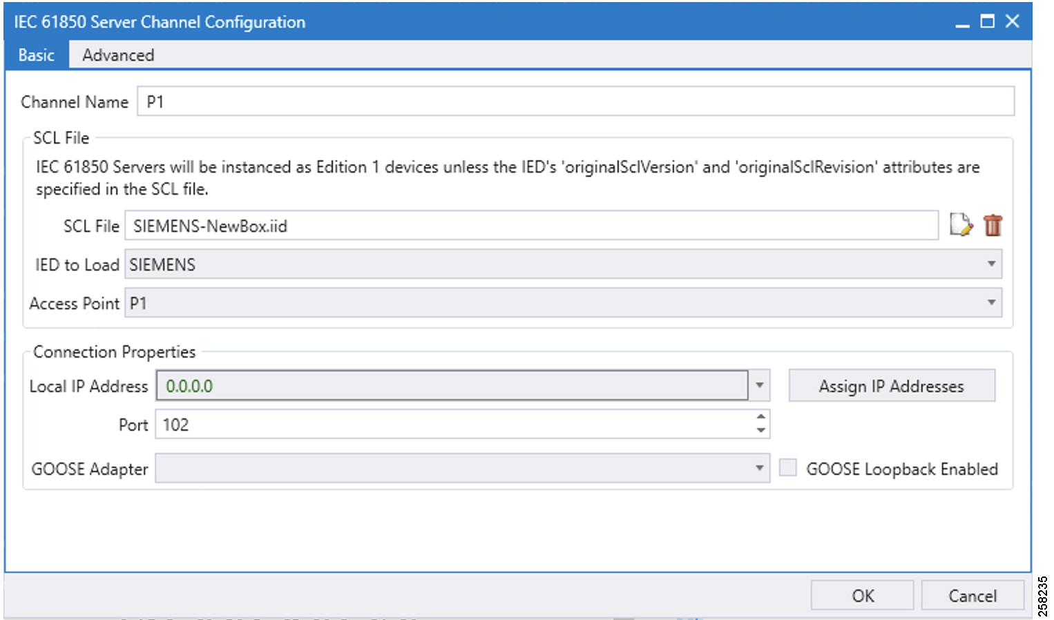
1.![]() Choose the appropriate deployment-specific SCL file. Then select the IED.
Choose the appropriate deployment-specific SCL file. Then select the IED.
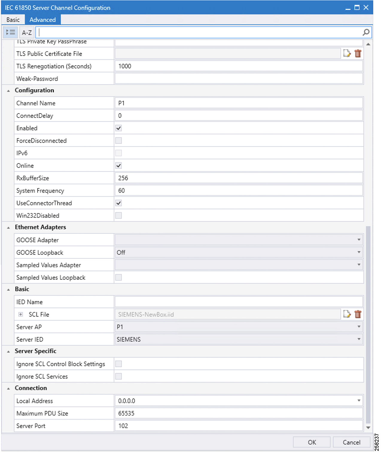
2.![]() In the Advanced Configuration tab, no changes are required. Figure 88 and Figure 89 are for reference.
In the Advanced Configuration tab, no changes are required. Figure 88 and Figure 89 are for reference.
Figure 88 IEC 61850 Advance Channel Configuration
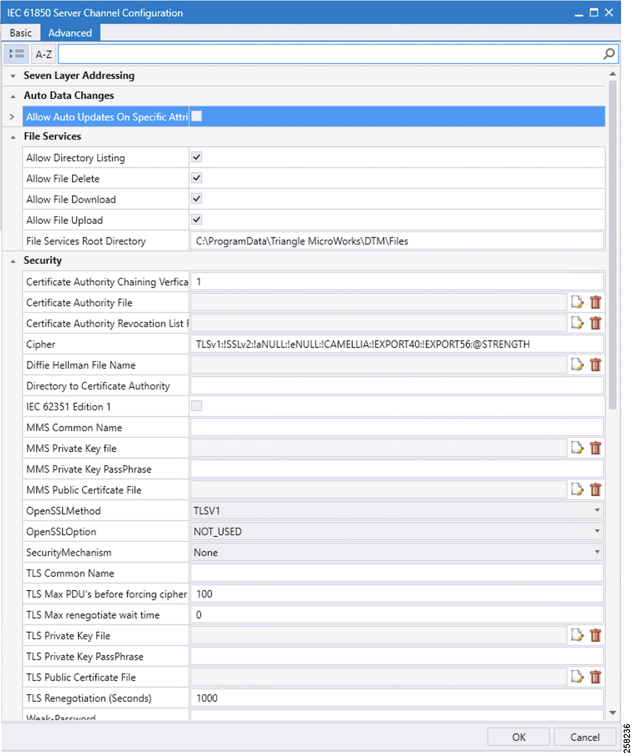
Figure 89 IEC 61850 Channel Configuration
Northbound DNP3 IP TMW Configuration
DNP3 IP Channel Configuration
The TMW DTM software is configured in the DNP3 IP. Master mode is used to simulate Control Center SCADA software. Port 2401 is used to communicate between the DNP3 master and slave running in ES 200. This port needs to be opened in IOX NAT mode, which will be defined in the package.yaml file. See Figure 90:
Figure 90 DNP3 IP Channel Configuration

DNP3 IP Session-related Configuration
Configure the DNP3 IP Link Layer address based on Virtual RTU ES200 database settings. See Figure 91:
Figure 91 DNP3 IP Session Configuration

DNP3 IP Advanced Settings
AutoTimeSyncIIN and AutoEnabledUnsol are advanced DNP3 IP settings, which need to be enabled; AutoIntegrityOnline and AutoIntegrityRestart settings need to be disabled. Please refer to Figure 92 for details:
Figure 92 DNP3 Advance IP Session Configuration

DNP3 IP (Control Center) to IEC 61850-MMS (IED) Register Mapping
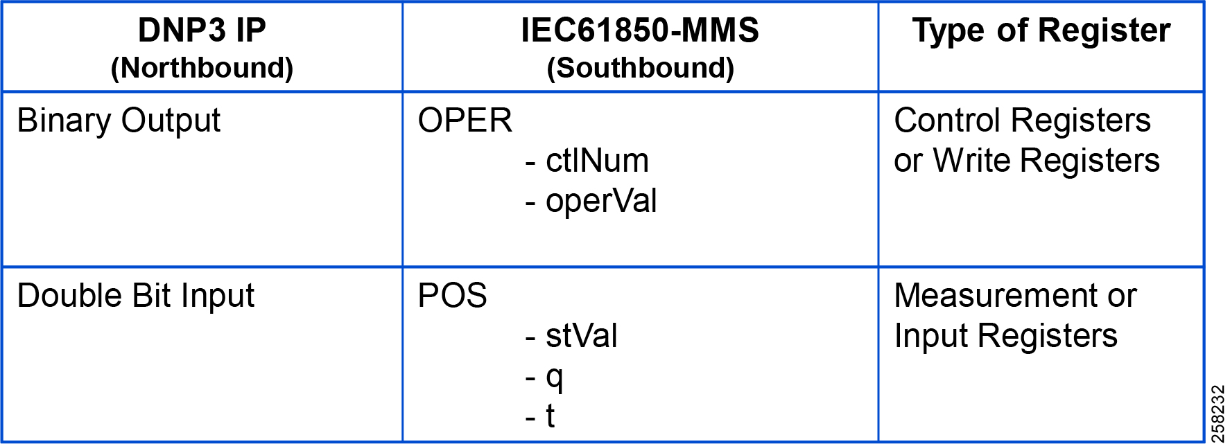
The ES200 Virtual RTU software maps and translates different registers in the IEC 61850-aware Southbound device to the DNP3 protocol-aware Northbound Control Center. The sample register mappings in use by the current version of the ES200 application evaluated in the Connected Utilities Solutions lab are shown in Figure 93:
Figure 93 DNP3 to IEC 61850 Point List Mapping
Note: Contact Eximprod's team for creating/modifying the point list mapping database, at the following URL:
Integrity Poll Use Case
The DNP3 specification supports multiple methods of reading inputs individually or as a group. An integrity poll returns data from Class 0 (known as static data), along with data from Classes 1, 2, and 3 (which will be event data). This may or may not be everything, depending on how the slave is configured.
The integrity poll retrieves all events (Class 1, 2, and 3) and static (Class 0) data from the device. It is typically sent after device restart, loss of communication, or on a periodic basis to ensure all data is accurate. This integrity poll is executed in our case from the Northbound DTM application depicted in Figure 94 and Figure 95:

Figure 95 Integrity Data Poll Class0123

1.![]() Click Apply and then click OK to initiate a poll. Poll results for the Northbound DTM application are shown in Figure 96.
Click Apply and then click OK to initiate a poll. Poll results for the Northbound DTM application are shown in Figure 96.
2.![]() Click the Show Point List option under the DNP3 IP Session.
Click the Show Point List option under the DNP3 IP Session.
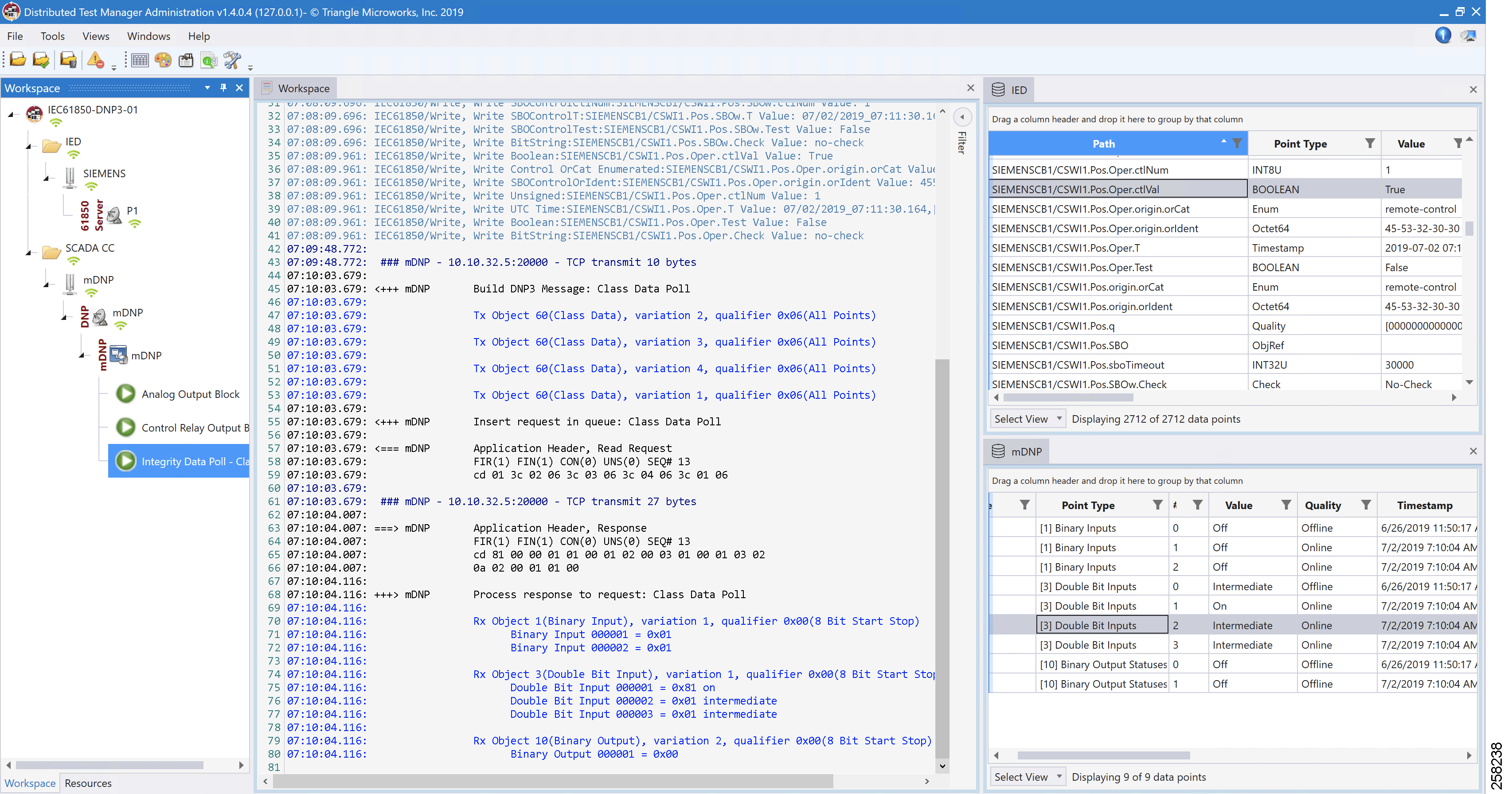
In the poll results on the Northbound simulator that are shown above, we received Double Bit input register values of DNP3. In the Southbound IED simulator, these are mapped to register Pos.Oper.stVal values.
Virtual RTU reconstruct the SCADA protocol, which matches the Southbound TMW application register values. Therefore, we conclude that the integrity poll is successful.
For the purposes of this document, we just discussed Double Bit Input register values for the Integrity poll.
Control Command
In DNP3, binary output statues registers will be used for control write operations. We will try to issue a CROB command from the Northbound DTM application to Boolean register on IED. IF send a control command to this Boolean register Pos.Oper.ctVal it will execute the command and also update the Double Point register Pos.Oper.stVal value of IED.
The status check on the Southbound TMW before issuing a control command from the Northbound. We can see the Boolean register Pos.Oper.ctVal status is False in Figure 97:
Figure 97 IEC 61850 Southbound Point List Status
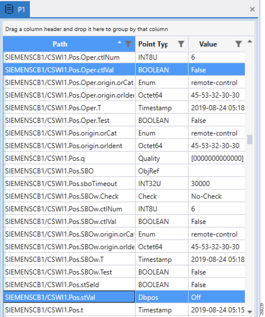
Now the control command is issued from the Northbound TMW simulator to change the state of the register to True/On.
Figure 98 DNP3 IP Northbound CROB Control Command
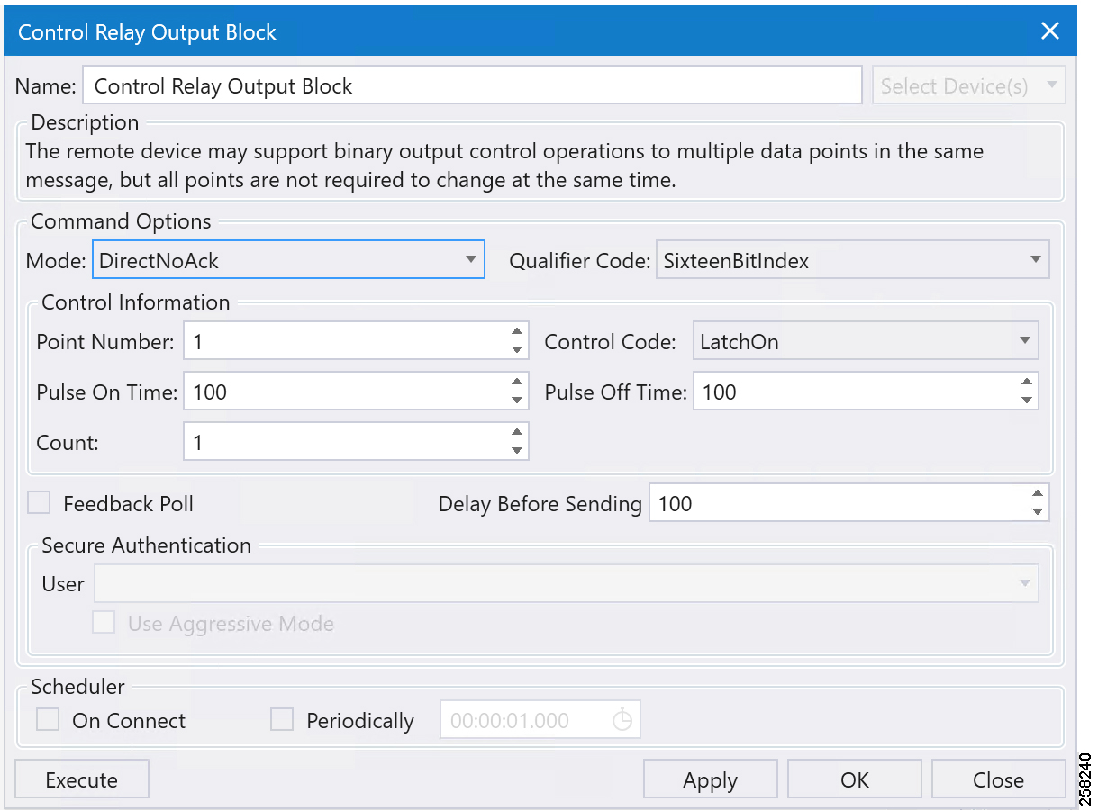
Command LatchOn is executed on Point Number 1 in Figure 98 above. Mode is DirectNoAck. Control Code is LatchOn. Click Apply and then click Execute to execute the command from the Northbound DTM application.
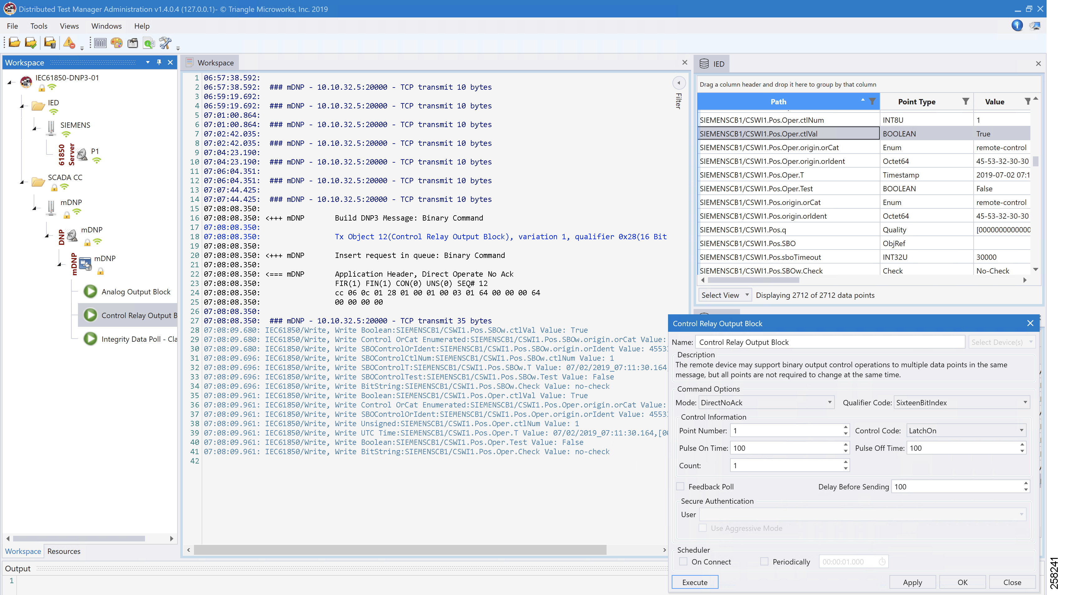
Binary Output Statuses Pos.Oper.ctVal register value on the Southbound TMW application is changed from False to True; this is depicted in Figure 99.
Figure 99 IEC 61850 Southbound Register Value Changed to True
IEC 61850-MMS (Southbound) to T104 (Northbound) Translation Use Case
Implementation Details
The Cisco IR809/IR1101 router is connected to an actuator or sensor in the Southbound via Ethernet and uses IEC 61850-MMS as the SCADA communication protocol. Virtual RTU software does the Northbound translation to T104 IP since the Control Center software is running the T104 IP SCADA application.
■![]() Southbound IEC 61850-MMS Actuator is simulated using TMW Test Harness application.
Southbound IEC 61850-MMS Actuator is simulated using TMW Test Harness application.
■![]() Northbound T104 SCADA Software is simulated using TMW DTM Application.
Northbound T104 SCADA Software is simulated using TMW DTM Application.
Figure 100 Implementation Details of T104 to IEC 61850 Translation - 1007

Southbound IEC 61850-MMS TMW Configuration
Channel Configuration
The Southbound IED is simulated using TMW software. In this example, the TMW simulated IEC 61850-MMS IED is connected to GigabitEthernet1 of IR809 or FastEthernet0/0/1 of IR1101.
Figure 101 IEC 61850-MMS Channel Configuration

Figure 102 IEC 61850 Advanced Channel Configuration

Figure 103 IEC 61850 Channel Configuration Advanced Continued

Northbound T104 TMW Configuration
Channel Configuration
The Northbound Ethernet SCADA Control Center is simulated using DTM software. In this example, Port 2404 is used for communication between the Northbound Control Center and the Virtual RTU ES200. See Figure 104:
Figure 104 Northbound T104 Configuration

T104 (Control Center) to IEC 61850-MMS (IED) Register Mapping
The ES200 Virtual RTU software maps and translates different registers in the IEC 61850-aware Southbound device to the T104 protocol-aware Northbound Control Center. The sample register mappings in use by the current version of the ES200 application evaluated in the Connected Utilities Solutions lab are shown in Figure 105:
Figure 105 T104 to IEC 61850 Point List mapping - 1008
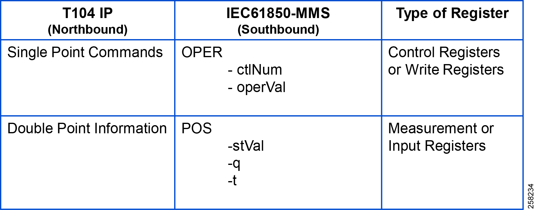
Reading IEC 61850 Southbound Data from Northbound T104 Control Center
As the register mapping depicts Double Bit Information in the Northbound T104, the Control Center is mapped to the Double Point register Pos.Oper.st in IEC 61850 Southbound device. Double Point Information in the Control Center should show the corresponding Double Point Binary values set in the IEC 61850 Southbound device.
Northbound Control Center General Interrogation
See Figure 106:
Figure 106 Reading Double Point Information
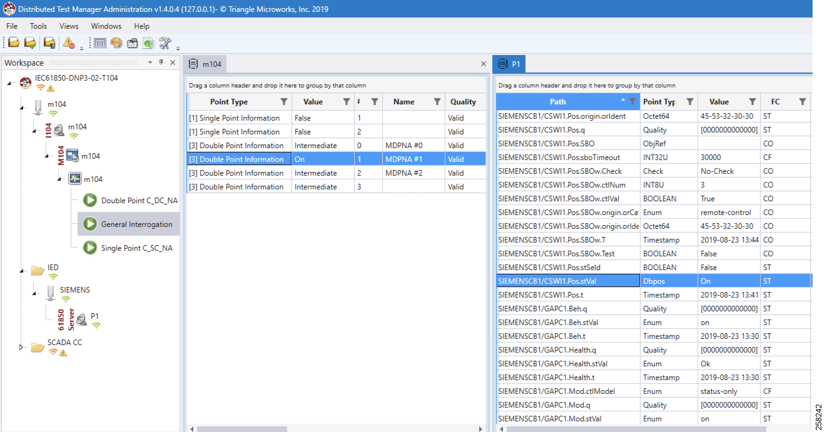
The Double Point register Pos.Oper.stVal on IED is read by the T104 General Interrogation command and the results are updated in Double Point Information register of T104 in Control Center.
Control Command
For the Control command example, a Single Point Control Command is sent from Control Center using the T104 protocol. The ES200 application translates T104 command to the IEC 61850 command, the southbound IEC 61850 IED Boolean register Pos.Oper.ctVal is updated with the control command, and also internally IEC 61850 updates the Double Point register Pos.Oper.stVal value of IED. This Double Point register Pos.Oper.stVal is read by T104 General Interrogation command and the results are updated in Double Point Information register of T104.
Initial status of Pos.Oper.ctVal and Pos.Oper.stVal registers of IED are shown in Figure 107:
Figure 107 IEC 61850 IED Initial Register Status
■![]() The register value of Pos.Oper.ctVal is False
The register value of Pos.Oper.ctVal is False
■![]() The register value of Pos.Oper.stVal is Off
The register value of Pos.Oper.stVal is Off
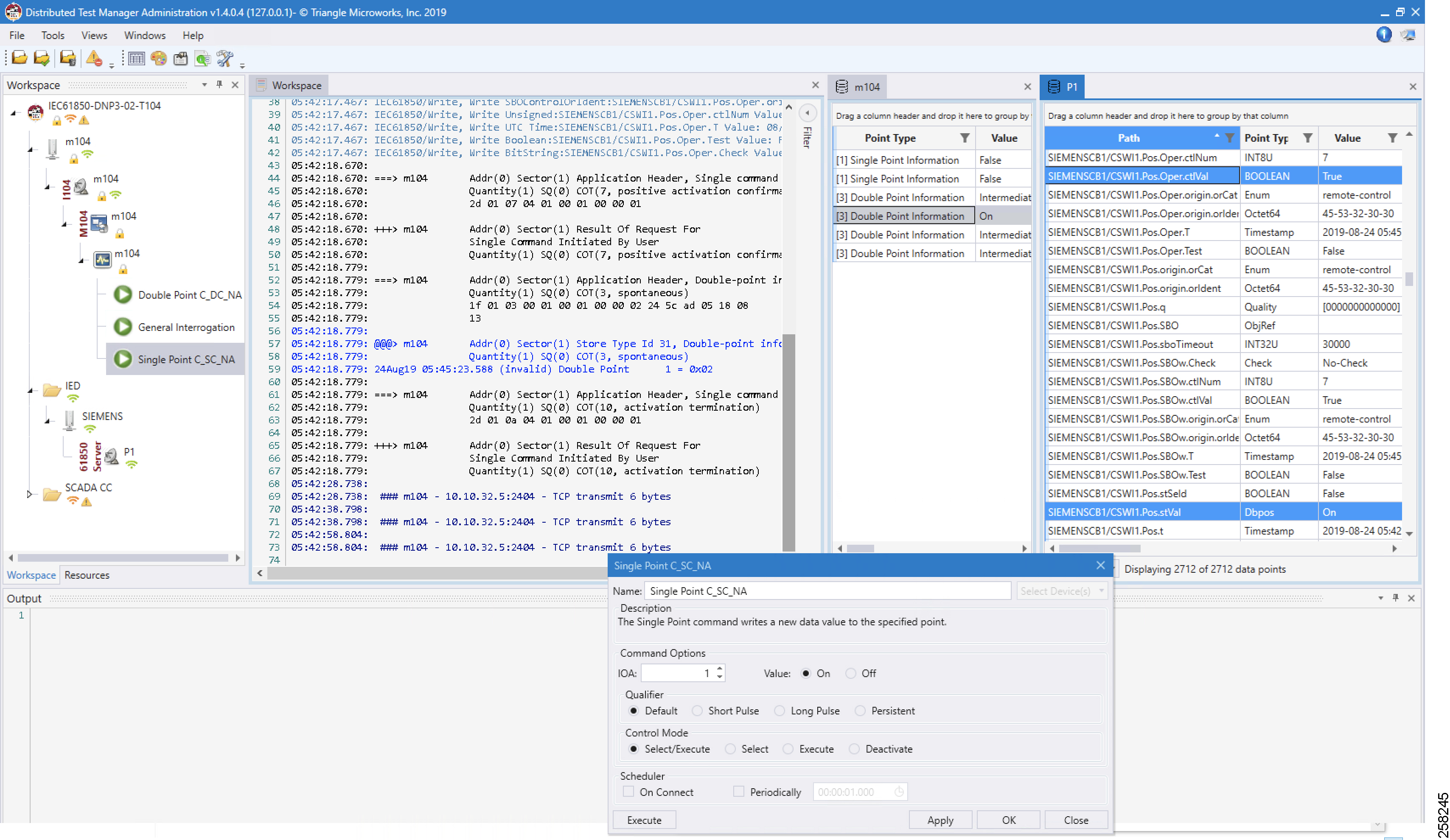
Figure 107 captures the Control Command from the Northbound application, which is configured to work in the T104 SCADA protocol. The Southbound application is configured to work in the IEC 61850 SCADA protocol. The intermediate Virtual RTU converts the T104 command into the IEC 61850 command. We are issuing a control command to toggle the value of register from False to True, which is depicted in Figure 108:
Figure 108 Single Point Control Command
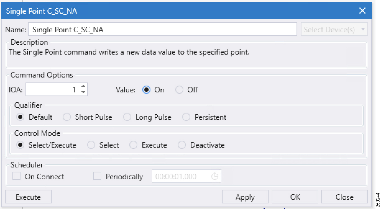
Single Point command is executed on IOA address 1 in Figure 108, with Qualified as Default and Control Mode as Select/Execute. Click Apply and then click Execute to execute the command from the Northbound DTM application.
Figure 109 IEC 61850 Double Point Status

■![]() The Double Point register value of Pos.Oper.stVal is On
The Double Point register value of Pos.Oper.stVal is On
■![]() The Boolean register value of Pos.Oper.ctVal is True
The Boolean register value of Pos.Oper.ctVal is True
The Southbound IEC 61850 IED Boolean register Pos.Oper.ctVal is updated in Double Point register Pos.Oper.stVal value of IED. This Double Point register Pos.Oper.stVal is read by T104 General Interrogation command and the results are reflected in the Double Point Information register of T104.
Limitations
This section covers the list of open limitations in the system.
The Virtual RTU ES200 database changes based on different protocol translations that need to be done manually by using the Windows-based ES200 desktop application. Then the database is exported to the Cisco IoT Gateway devices. Eximprod is working with the Cisco Fog Director Team to bring in support for editing the ES200 database from the Fog Director.
References
Cisco Documentation
Cisco IR809: Cisco 809 Industrial Integrated Services Routers Data Sheet at the following URL:
■![]() https://www.cisco.com/c/en/us/products/collateral/routers/809-industrial-router/datasheet-c78-734980.html
https://www.cisco.com/c/en/us/products/collateral/routers/809-industrial-router/datasheet-c78-734980.html
Cisco IR1101: Cisco IR1101 Industrial Integrated Services Routers Data Sheet at the following URL:
■![]() https://www.cisco.com/c/en/us/products/collateral/routers/1101-industrial-integrated-services-router/datasheet-c78-741709.html
https://www.cisco.com/c/en/us/products/collateral/routers/1101-industrial-integrated-services-router/datasheet-c78-741709.html
Cisco ASR 1000: Cisco ASR 1000 Series Aggregation Services Routers at the following URL:
■![]() https://www.cisco.com/c/en/us/products/routers/asr-1000-series-aggregation-services-routers/index.html
https://www.cisco.com/c/en/us/products/routers/asr-1000-series-aggregation-services-routers/index.html
Cisco Fog Director at the following URL:
■![]() https://www.cisco.com/c/en_in/products/cloud-systems-management/fog-director/index.html
https://www.cisco.com/c/en_in/products/cloud-systems-management/fog-director/index.html
Cisco IOx Data Sheet at the following URL:
■![]() https://www.cisco.com/c/en/us/products/collateral/cloud-systems-management/iox/datasheet-c78-736767.html
https://www.cisco.com/c/en/us/products/collateral/cloud-systems-management/iox/datasheet-c78-736767.html
Eximprod Documentation
ES200 Data Sheet (ES200 Supervision, Control and Communication RTU Gateway) at the following URL:
■![]() http://www.epg.ro/wp-content/uploads/2017/09/ES200-Datasheet-public.pdf
http://www.epg.ro/wp-content/uploads/2017/09/ES200-Datasheet-public.pdf
General Documentation
EuroElectric Power Distribution in Europe Facts & Figures at the following URL:
■![]() https://www3.eurelectric.org/media/113155/dso_report-web_final-2013-030-0764-01-e.pdf
https://www3.eurelectric.org/media/113155/dso_report-web_final-2013-030-0764-01-e.pdf
Glossary
The following table lists and expands the acronyms and initialisms used in this document.
 Feedback