- Solution Overview
- Chapter 1 Introduction
Grid Security Design Guide
Solution Overview
The physical and cyber security of the utility grid with associated operational monitoring and control networks has been an increasing source of global concern and regulatory mandates. Electric utility operators are changing their operational model and adopting new technologies. These changes are being driven by flat-to-declining revenues, grid stability issues because of renewables, the increasing dynamic load of electric vehicles, and a declining work force. Legacy control systems are no longer cost effective to operate and are virtually impossible to secure.
These changes have also brought about significant legislative and government mandates to ensure a stable and operational grid. These compliance mandates often create additional concerns and expense. Unsecured devices are now both a cyber security risk as well as a compliance threat. The adage “You cannot secure what you cannot see” has never been more applicable. The utility industry is rapidly migrating to a digital world. This transformation from proprietary siloed systems to a single digital standards-based system offers the opportunity to improve and secure the grid operational network.
A pervasive, highly available, and well-designed communications network will help enable increased reliability and availability while also reducing operational expenses. Cisco Systems is addressing the security requirements of the utility industry with a suite of integrated and validated security solutions. These integrated solutions will also help ease compliance concerns, complexity, and costs.
The Cisco Grid Security solution, part of the Cisco portfolio of solutions for substation automation, utility WAN, and Field Area Network Advanced Meter Infrastructure (FAN AMI) provides the following with unique capabilities for electric grid operators:
■![]() Cisco Cyber Vision is capable of non-intrusively monitoring OT protocols and identifying devices on the grid. Cisco Cyber Vision provides device-level visibility and status and operational personas of grid assets, such as device make, model, and firmware level.
Cisco Cyber Vision is capable of non-intrusively monitoring OT protocols and identifying devices on the grid. Cisco Cyber Vision provides device-level visibility and status and operational personas of grid assets, such as device make, model, and firmware level.
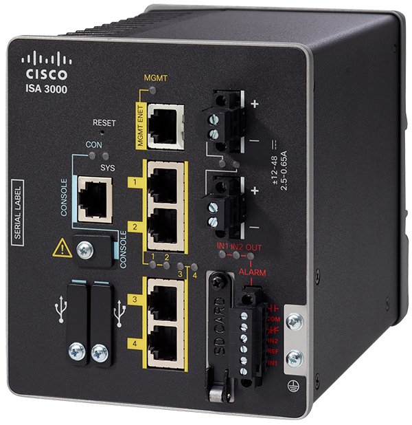
■![]() Cisco ISA 3000 industrial security firewall is a purpose built, fully ruggedized firewall leveraging the Cisco Firepower Next Generation Firewall (NGFW) with the added IoT-specific signature base to identify industrial protocols and perform deep packet inspection, segmentation, and enforcement.
Cisco ISA 3000 industrial security firewall is a purpose built, fully ruggedized firewall leveraging the Cisco Firepower Next Generation Firewall (NGFW) with the added IoT-specific signature base to identify industrial protocols and perform deep packet inspection, segmentation, and enforcement.
■![]() Integration of CyberVision and the ISA-3000 to a 3rd party SIEM.
Integration of CyberVision and the ISA-3000 to a 3rd party SIEM.
■![]() Cybervision deployed as a network sensor on both the IE3400 switch as well as on the IR1101 secure gateway.
Cybervision deployed as a network sensor on both the IE3400 switch as well as on the IR1101 secure gateway.
■![]() Compliance mapping for NERC CIP mandates addressed by this Grid Security CVD.
Compliance mapping for NERC CIP mandates addressed by this Grid Security CVD.
This guide describes the Cisco Grid Security solution, which is based on industry-leading innovations in device discovery, anomaly detection, segmentation, isolation, profiling, and enforcement. Cisco networking technologies and the security features integrated into them allow the utility operator to turn every Cisco edge switch port and every routing hop on every Cisco switch and router into a security device, from deep in the substation network to the control and operations centers, forming an integrated and validated security system.
Navigator
Table 1 describes the sections in this document.
|
|
|
An overview of the existing security models and best practices to address the digital migration for the utility grid. |
|
This chapter discusses places in the network, system architecture, and solution components. |
|
This section discusses security architecture for Substation Automation Systems. |
|
This section discusses security architecture for Distribution Automation. |
|
Chapter 5 Design OT Visibility, Anomaly Detection and Mitigation |
This chapter discusses design aspects for OT visibility, anomaly detection and mitigation. |
This section discusses design aspects with respect to scale, performance, and final summary. |
|
Audience
The audience for this guide includes customers that are chief information security officers, system architects, security architects, OT network, compute, and systems engineers, field consultants, Cisco Advanced Services specialists, and others.
Readers may be familiar with networking protocols, SCADA protocols, compliance requirements, and basic security best practices associated with an OT network and associated grid topologies.
Document Objective and Scope
This document provides a comprehensive explanation of Cisco Grid Security system design. It includes information about the system architecture, possible deployment models, and guidelines for implementation. Recommended best practices and deployment issues are included.
Chapter 1 Introduction
Security Concerns in the Changing Utility Landscape
The utility industry is undergoing a number of significant changes. Grid design at the distribution layer is moving to a more dynamic model incorporating intelligent devices at or near the edge. The inclusion of residential and commercial solar, the islanding and re-connection of micro-grids, and even the dynamics of electric vehicle charging are increasing challenges on grid operators to maintain a stable and reliable electrical distribution network. Grid operators cannot maintain the necessary stability without load demand information and in some cases predictive analysis based on historical data.
Grid Digitalization
A secure and highly reliable data network to the edge of the grid is required to deliver the data on which the operators rely so heavily. The ability to adjust the grid remotely in real time or use remote compute and analytics to automatically make changes in the grid is being referred to as the digitalization of the utility grid. This digitalization of the grid and the migration to a more dynamic grid is a necessary progression, and it exponentially increases the attack surface.
Design of the utility grid has not changed significantly in the last 100 years. The current shift to a more connected and data-driven operation of the grid is necessary to maintain stability due to the dynamics at the consumer edge. The increasing number of devices connecting to the grid demand a properly architected grid that can be safer, more reliable, and more secure. When establishing device logging, encryption, and threat analytics throughout the data network to the edge, the data network actually becomes a security tool. This secure network delivers trusted real time visibility to the device behavior operating the grid from the control center to the operational status of each device in the substation and eventually to the edge.
Substation Digitalization
Digitalization also occurs in the substations. Transformers, RTUs, relays, and PLC designs are all moving away from legacy and proprietary interfaces—and typically slower serial interfaces—to a more common and standards-based Ethernet communications interface. It may be difficult or financially challenging for a utility operator to migrate an entire substation at one time from a serial-based control network to an Ethernet network, so this migration is often done piecemeal or as assets age out. This makes developing a migration strategy critical.
Migration Strategies
Migration security strategy starts with device visibility and a clear understanding of the existing asset posture in the substation. Once the devices are known, a vulnerability assessment is critical and a remediation plan for devices with known vulnerabilities is necessary. If some devices cannot be patched at this time, an external scheme must be designed to protect them from remote or unauthorized access. Numerous tools are available including port security features, MAC ACLs and application layer profiling, and micro-segmentation, to name a few. The concept is to lock the device down at the point it accesses the network and only allow it to communicate with the specific devices necessary to complete its operation.
Terminal servers are often deployed for devices requiring serial connections; these should be eliminated or at least secured in a similar way. Most serial-based SCADA protocols can be transported over a packet (Layer 3) network using tunneling technologies (TCP-RAW-SOCKET) to a secure control center. This provides a single security point for assessment and helps to further reduce the vulnerabilities at the edge.
Ongoing Substation Monitoring
Once an assessment is completed, the migration or upgrade/replacement of end devices is in progress or even complete in the substation, ongoing monitoring of low level traffic flows is necessary. Details about communication peers on the process bus or between the process bus and station bus, for instance, are necessary to ensure stable operations.
Continued monitoring of peer-to-peer and client-to-server (SCADA) protocols and communication flows is also necessary to maintain a secure posture. Security can not be maintained with a “set-and-forget” approach. Continuous monitoring, especially for anomalous behavior and the secure alerting of any status changes, unplanned device additions, or deletions is necessary and often required by compliance mandates.
Physical Security
Cyber security is not the only security concern. Physical security and the monitoring capabilities that come with it have also seen significant improvements in the last few years. Monitoring the physical security of remote assets, such as a substation or a recloser cabinet on a pole, is part of the effort to improve reliability and prevent unwanted access, malicious attacks, and theft to address worker safety and security concerns. Video cameras, badge readers, and other sensors are being integrated to identify users authorized at a physical location.
Acoustical sensing and laser technologies are able to help eliminate false positives by identifying approaching vehicles that are continuing or stopping, and identifying and discriminating between animals and humans. A solid physical security system may be an early warning system for cyber security. These layered sensing technologies tied in with video provides a security team with much more detailed information about a possible threat, intruder, employee in a facility, or simply the status of a remote asset under both normal and adverse conditions. Consider the savings if storm damage can be assessed before dispatching a crew.
Data from these physical security devices and monitoring systems have the potential to oversubscribe a network, particularly a bandwidth-constrained wide area network. These monitoring systems are often lightly monitored and have little output unless triggered; they then tend to generate high traffic or bursts that must be accommodated. These bursts and any event alerts, either physical security or cyber security alerts, can be dealt with in a number of ways including a structured QoS scheme, alternate paths via a secondary WAN connection such as a low cost cellular or DSL connection utilizing either SD-WAN, or other least-cost routing mechanisms.
Use Cases
Generic use cases for Grid Security are discussed below. Deeper-dive use cases for Substation Automation Systems and Distribution Automation are discussed in subsequent chapters.
Network segmentation
Industrial security best practices suggest migrating networks towards architectures compliant with IEC62443 zones and conduits. In other words, you want to place assets that do not need to talk to each other into isolated network segments to help prevent an attack from spreading to your entire industrial infrastructure. NERC CIP compliance dictates multiple segmentation “zones” based on criticality of assets in a substation and between substations.
Authentication, authorization, and accounting
Access control is identification and authentication control in the utility environment, means to verify the identity of users (humans, software processes, devices) requesting access before activating communication. The aim is to prevent illegitimate (unauthenticated) access of selected devices or data. It is important to define what devices are connected to a network, at what location, and who is operating that device. Allow only known users. Limit number of devices connected to Substation Bus or Distribution Automation Gateways. Prevent rouge devices/users accessing the network. Control and limit access to the resources. Maintain logs of users OT transactions and events.
Secure Data Transport
Data integrity is critical to the operations of the grid. Grid operators depend on secure data transport for real time and near time monitoring data as well as remote operational modifications and results of those changes to determine if further actions are necessary. Compliance mandates separation of critical data and encryption of data exiting a physical perimeter. Logging information must also be maintained with proof of secure delivery to the logging collector and storage facilities.
Operational visibility and insights
Know what to protect. Insights into assets and OT flows. Keep track of process, data, asset modification and variable changes which in-turn helps to maintain system integrity and operation continuity.
Threat Detection and mitigation
360° threat detection—Detect threats before it is too late. Abnormal traffic detection and mitigation post thread detection. Protect critical assets against cyber-attacks and insider threats. The anomaly detection is the process to determine which observed events are to be identified as abnormal because it has significant deviation from normal behavior which is called baseline.
Chapter 2 System Architecture
Grid Security Architecture is a holistic security architecture built on top of existing Cisco Substation Automation and Field Area Network Solution. It is important to understand actors involved and messages exchanged between them. We will start by understanding different Places in the Network (PIN) for Grid Security Architecture and various Cisco security features applicable to each tier. The discussion is followed by Grid Security Solution topology and Solution components.
Grid Security Places in the Network
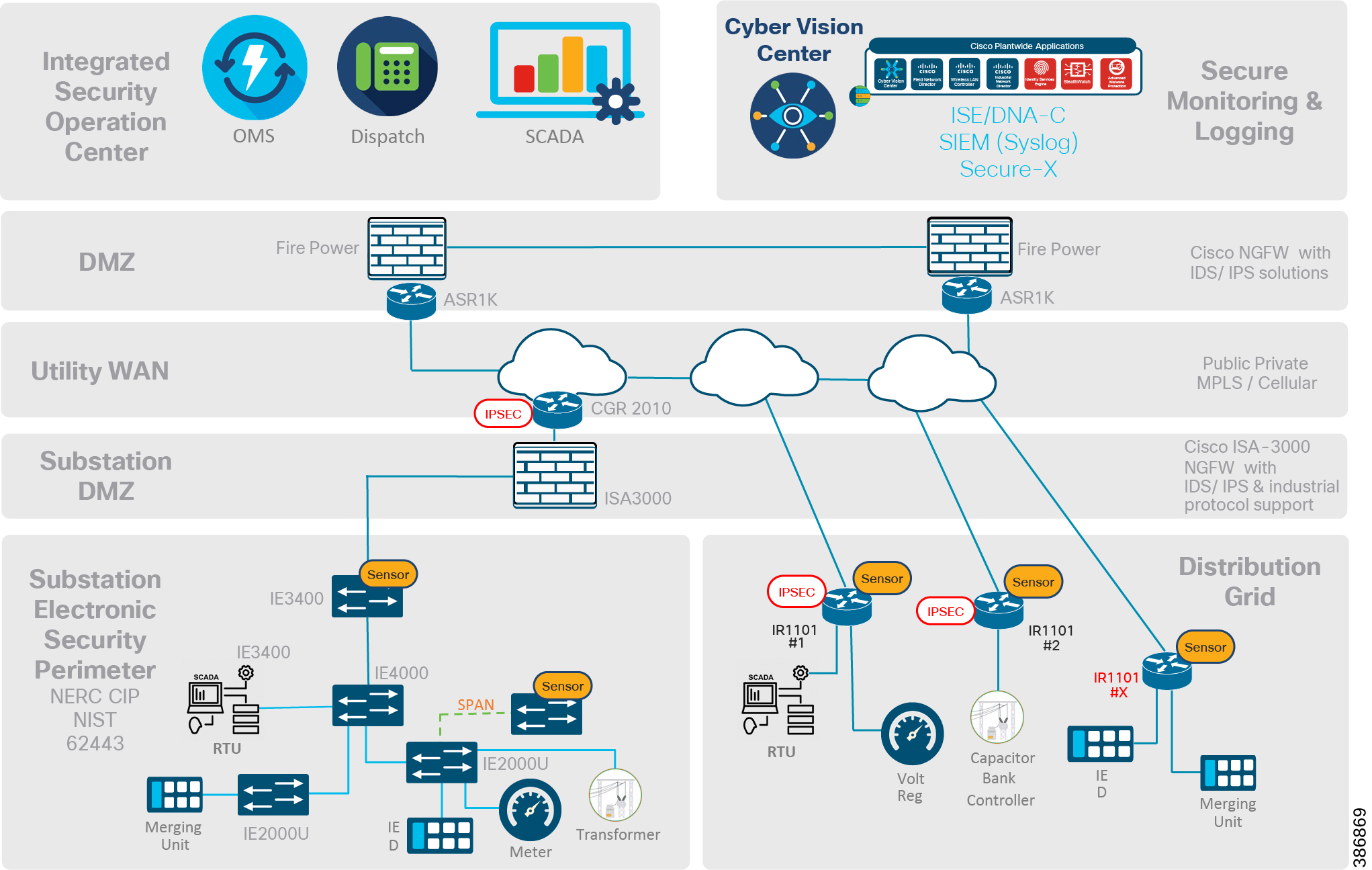
Grid Security Solution can be divided into five tiers as depicted in below figure
■![]() Integrated Security Operation Center (ISOC)
Integrated Security Operation Center (ISOC)
■![]() Substation Electronic Security Perimeter in case of Substation Automation Systems and Distribution Automation in case of Distribution Grid.
Substation Electronic Security Perimeter in case of Substation Automation Systems and Distribution Automation in case of Distribution Grid.
Figure 1 Grid Security Places in the Network
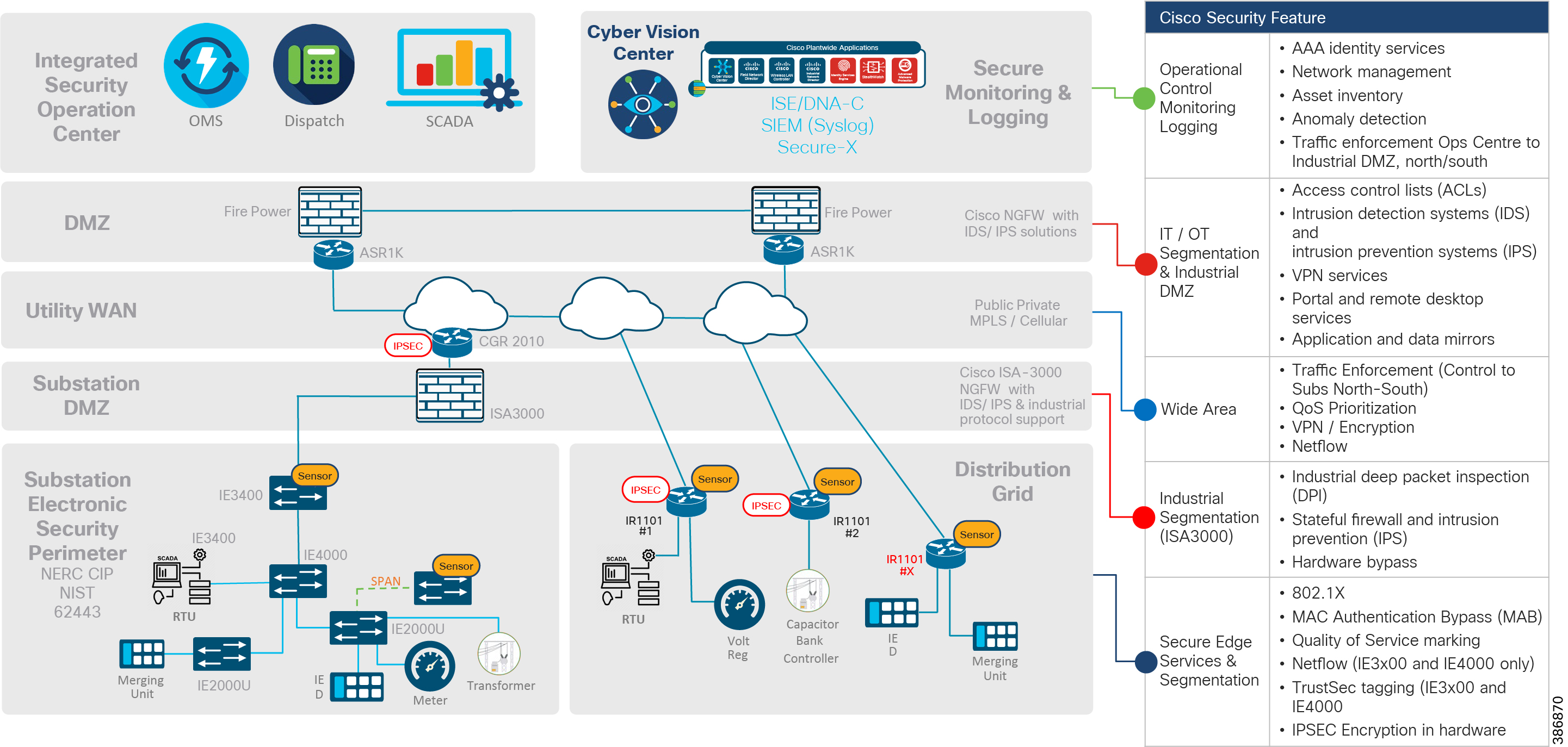
Cisco Defense in Depth Security Features mapped to different tiers
Figure 2 Grid Security feature mapping
ISOC Tier
The Cisco defense-in-depth security features and appliances are positioned in the ISOC layer for AAA Identity and policy management, network management, inventory management, OT Visibility, security monitoring, logging and interface to external cloud threat feed systems, information sharing, and access to analysis centers/external law enforcement systems.
Headend DMZ Tier
The Cisco Next Generation Firewall (NGF) along with Headend router (HER) in the DMZ layer provides intrusion detection and prevention, deep packet inspection, firewall and VPN termination capabilities.
Utility WAN Tier
The Cisco Substation Router for Substation Automation Systems and Distribution Automation Gateway for Distribution Automation provides data encryption and QoS prioritization SCADA traffic, VPN services for remote work force and device access, and zone-based firewall for traffic enforcement between substations and controller center or between substations.
Substation DMZ Tier
The Cisco Substation firewall provides the segmentation capabilities for subdividing substation into multiple zones and defining policies for intra- and inter-zones traffic flows. Stateful firewall and intrusion protection features of substation firewall provides strong threat detection capabilities.
Substation and Distribution Feeder Tier
Authentication and authorization using the Cisco 802.1x or MAC Authentication Bypass features prevents illegal or unauthorized access to utility devices. Cisco flows monitoring features like NetFlow and Flexible NetFlow (FNF) provide solid monitoring and logging capabilities. QoS features act as first level defense for throttling over-subscription traffic and provide differentiated services for high priority traffic.
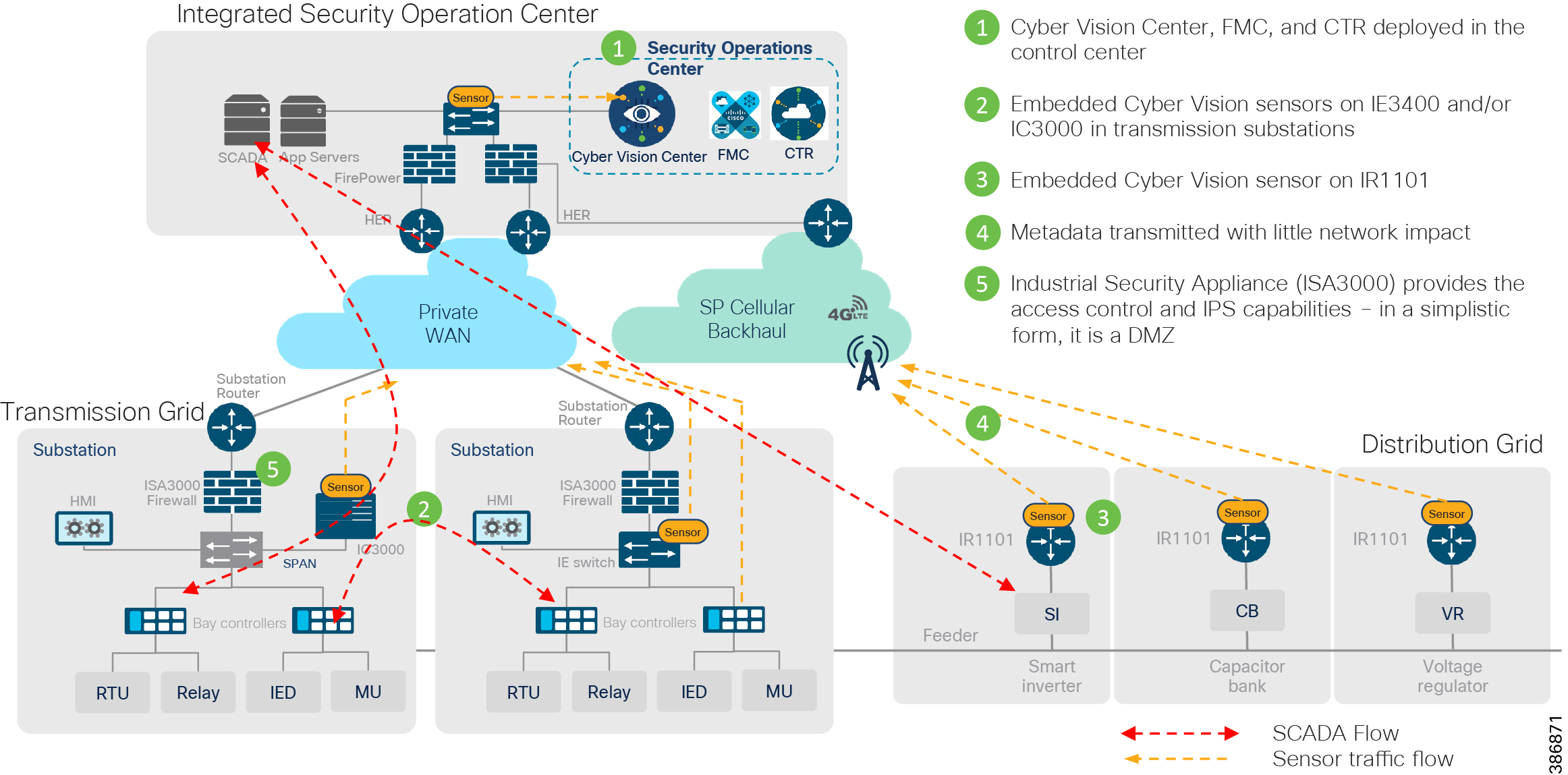
Grid Security Architecture
Figure 3 Grid Security High Level Architecture
Grid Security Solution proposes steps like identifying various assets in the network, define policies for segmentation, detect intrusions, anomalies and remediate as shown in the following figure to help achieve a secure Grid Network. The various components, considerations and mechanisms to achieve the same are listed and discussed in various chapters of this design guide.
Figure 4 Grid Security Four Step Journey
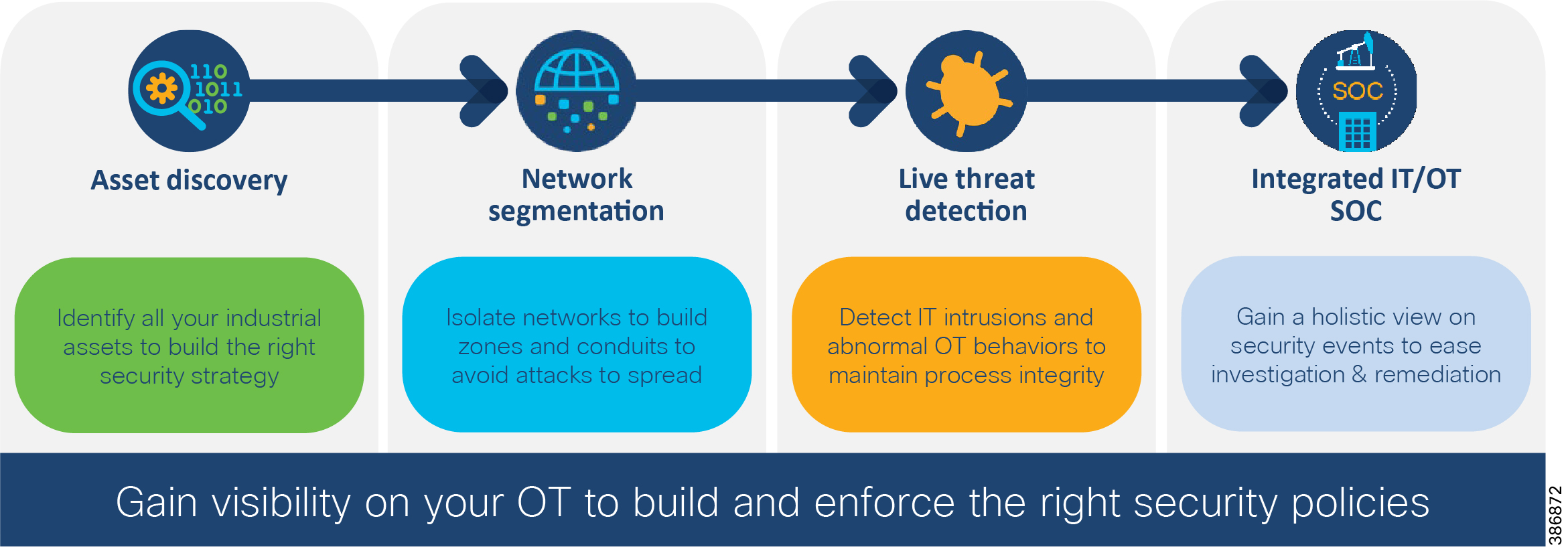
Grid Security solution design incorporates steps as listed above using various components, NERC-CIP compliance requirements on a centralized architecture. For NERC-CIP compliance requirements and various product mappings refer Appendix B and C. The following table maps various requirements of NERC-CIP and Cisco Grid Security Solution.
Table 2 NERC-CIP Compliance and Solution Mapping


The Integrated Security Operation Center tier and DMZ tier are (mostly) co-located and act as a brain for the solution. These combined layers form the Head End. Headend facility hosts various functions like Network, Network Management, Security Management, Application, among others.
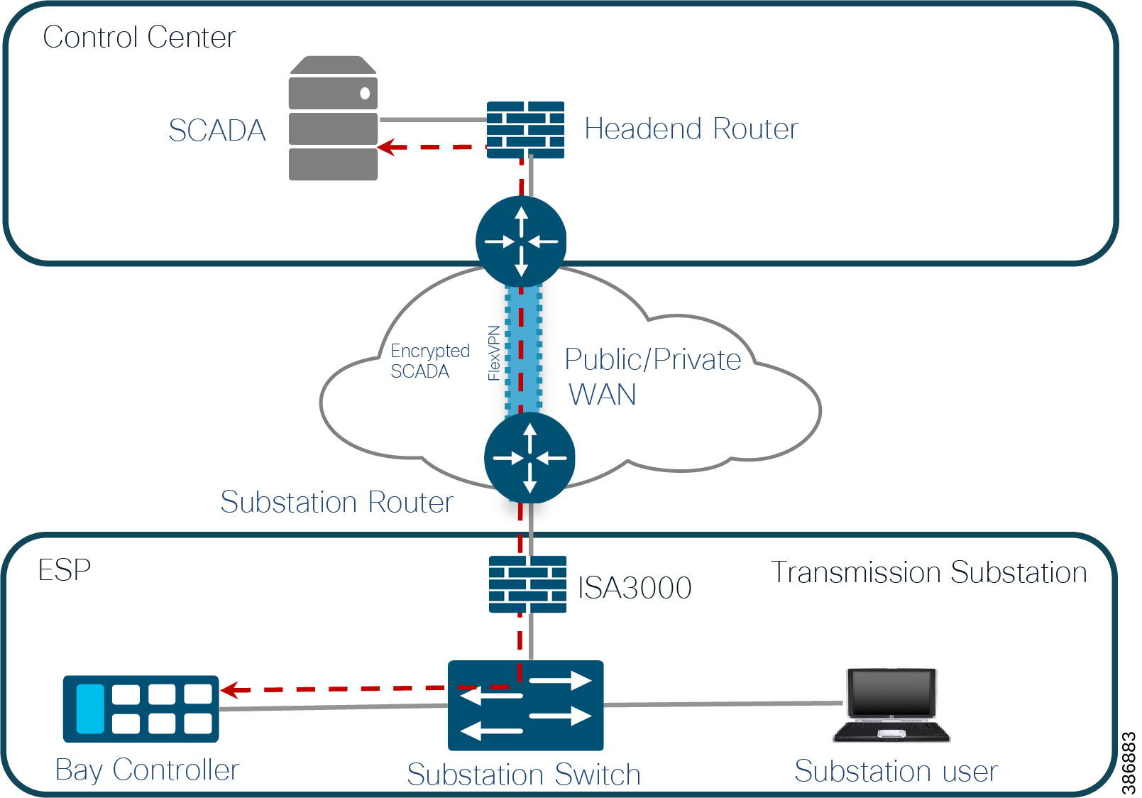
The majority of grid operation flows are centralized between SCADA applications in headend to outstation Intelligent Electronic Devices (IED) in transmission substation/secondary substation/distribution grid based on use cases. Some flows will be peer-to-peer between IEDs like protection use case in substation automation systems. Centralized application flows from substation to control center and vice versa, and substation to other substations flows over public or private network (WAN TIER) need to be encrypted.
Apart from OT flows, there are network management and other IT application flows between Headend and devices in the substation. An example of network management is centralized management of the substation switch, router, and firewall. Similarly, IP camera is used in Substation for physical safety and security operations. IP cameras will generate CCTV video feeds which might have to be managed from Headend application. Grid Security requires segmentation between various traffic types. Segmentation design is discussed in Chapter 3 and Chapter 4 of this guide.
The Cisco Headend Router (HER) provides encryption and decryption functionality and aggregation of different tunnels coming from different substation routers for both transmission and distribution. It is recommended to use Cisco FlexVPN for network layer encryption. The Cisco Substation Router and Distribution Automation Gateway perform encryption/decryption functionality on the other end.
The HER can be deployed in clustering mode for high availability. Post-HER traffic is routed to the headend firewall for IPS and DPI functionality. After successful firewall inspection based on traffic type is switched to various applications as discussed above.
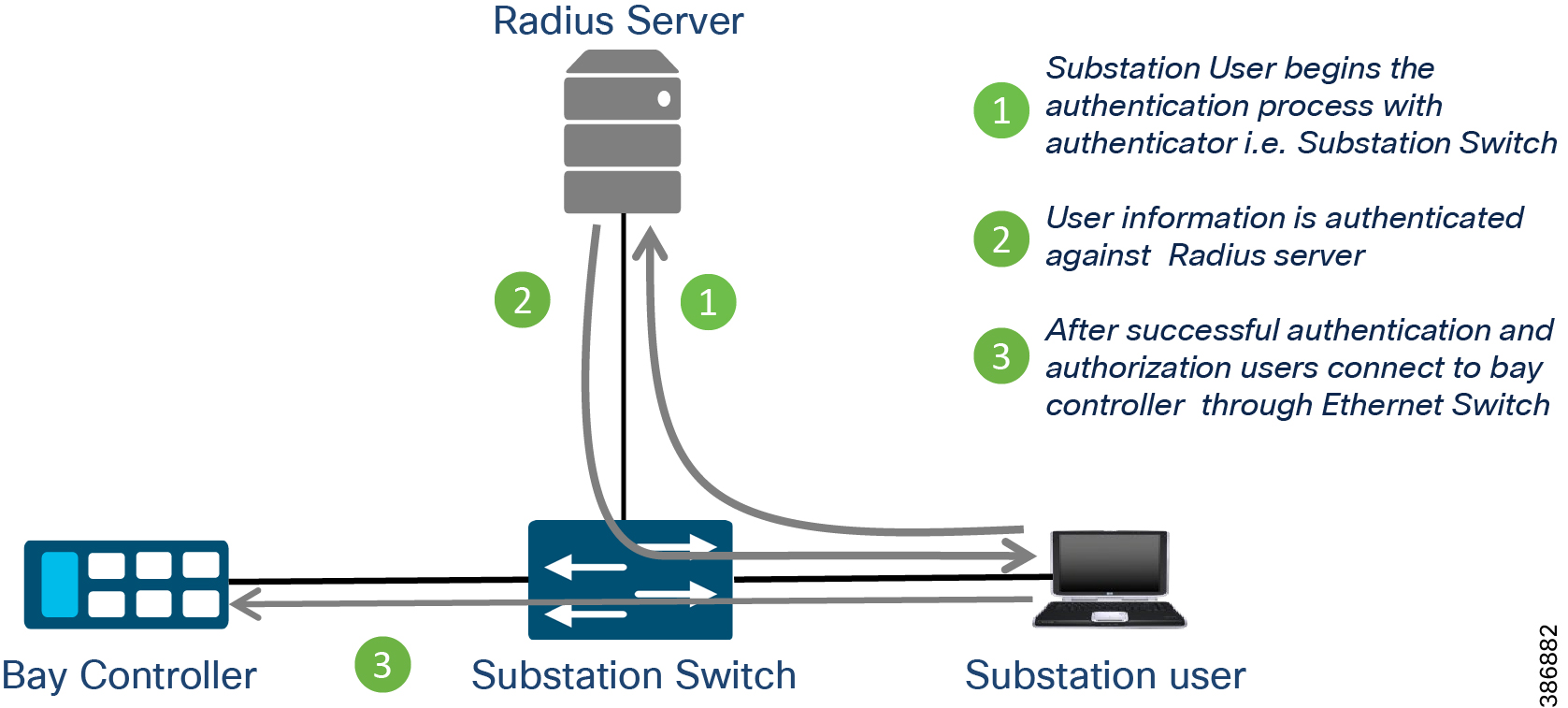
Now we understand the kind of traffic that can originate from the substation to headend and vice versa. It is important to have access control of end devices like IEDs and user access to IEDs for various remote management and troubleshooting purposes. Grid security architecture recommends end device authentication using IEEE 802.1X or MAC Authentication Bypass techniques to gain network access. The substation switch or Distribution Automation Gateway acts as authenticator initiating RADIUS sessions with Cisco centralized policy server Identity Service Engine (ISE). The ISE in turn can check with the utility owned Active Directory for authorization access. The ISE can push associated network configuration on the access port of the switches or router. Access port configuration can include VLAN for segmentation and QOS for in-bound policing and marking for preferential treatment for certain traffic types. Upcoming sections include more on design aspects for access control and segmentation: how Cisco Industrial Security Appliance ISA3000 can help to create and operate separate zones for critical grid operation and on the Electronic Security Perimeter zone requirement defined in NERC CIP standards.
Day-0 security design like access control, segmentation, and network encryption aspects have been discussed. A brief discussion follows about day-n security design aspects like visibility of operation traffic, anomaly detection and mitigation. Chapter 5 of this design guide explains in detail about design aspects of day-n security requirements.
Cisco Cyber Vision center brings visibility to aspects of various SCADA protocols like DNP3 IP, IEC 60870-5-104, IEC 61850 MMS, Modbus TCP and Legacy SCADA protocols like IEC 60870-5-101 and DNP3 used in the utility industry. Cisco Cyber Center will be deployed in the headend, and Cyber Vision sensors will be deployed in substations and distribution feeders. These sensors passively monitor and analyze the various SCADA flows and send the metadata to the Cyber Vision Center to enable device and flow visibility. A baseline of SCADA flows can be defined to detect the changes in OT end point and flows.
Two types of sensors are supported: network sensors and hardware sensors. For deployment where monitoring traffic needs to be maintained separately, we recommend a hardware sensor like Industrial Compute Gateway (IC3000) running the sensor application. For other deployments, network sensors like Cisco IE3400 and IR1101 are recommended. the Cisco IE3400 acts as substation switch and hosts Cyber Vision Network sensor software in the IOX core as an Edge Compute application. Similarly, the Cisco IR1101 acts a Distribution Automation Gateway for hosting sensor software in IOX.
The Cisco Industrial Security Appliance has defense-in-depth security features like SCADA pre-processors with intrusion rules and application identifier for visibility and control of individual protocol commands and values. Along with Cisco Cyber Vision, it helps in threat identification and mitigation.
Grid Security Components
The table below indicates the role of components used in the Grid Security solution.
Table 3 Solution Components and Roles
Cisco ISA3000 Industrial Security Appliance
The Cisco ISA3000 Ruggedized Security Appliance includes services for Firewall, VPN and IPS, DHCP, NAT, and OT deep packet inspection features. It provides first level of security connectivity using zone segmentation and next level visibility and control for OT protocols.
The ISA3000 runs Firepower Thread Defense software (FTD), a unified software image which includes the ASA features and Firepower services. This unified software offers the functionality of ASA and Firepower in one platform, for both hardware and software. This enables a unified security policy that is managed either with Firepower Device Manager (FDM) or using the central management with Firepower Management Center (FMC). FDM is suggested for single substation management/local management to simplify management and operations. FTD also provides REST APIs for automation or to integrate with the customer existing system.
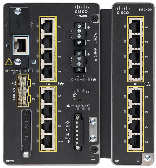
Cisco IE3400 Industrial Series Ethernet Switch
Industrial Series Ethernet Switches provides following security features:
■![]() MAC Authentication Bypass (MAB)
MAC Authentication Bypass (MAB)
For network resiliency Parallel Redundancy (PRP), HSR and Reliance Ethernet Protocol (REP) protocols are supported. The Industrial Serial Ethernet Switch IE3400 has Edge Compute capability to host Cyber Vision Network Sensor application. The IE3400 can be deployed in dual roles, both substation switch and inline network sensor.
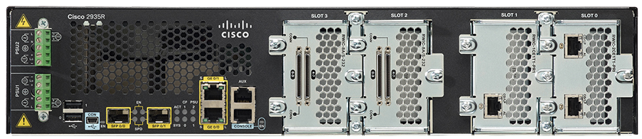
Cisco IR1101 Industrial Series Router and CGR2010 Substation Router
The Cisco IR1101 Industrial Series Router offers multi-layer security features for mission-critical OT deployments. Hardware-accelerated Next Generation Encryption enables security connectivity of OT traffic. Multiple OT traffic can be segmented using VRF and VLAN features. Zone-based firewall feature can be enabled for threat control. IEEE 802.1X and MAB features are supported for access control of OT end points.

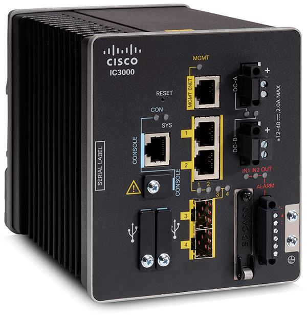
Cisco IC3000 Industrial Compute Gateway
The Cisco IC3000 Industrial Compute Gateway combines hardware and software security features to address these OT Security requirements:
■![]() Tamper-proof hardware: The Anti-Counterfeit Technology2 chip guarantees that you are using genuine Cisco hardware.
Tamper-proof hardware: The Anti-Counterfeit Technology2 chip guarantees that you are using genuine Cisco hardware.
■![]() Secure application hosting environment: The Cisco IC3000 uses a secure boot mechanism to load only the genuine Cisco Linux Kernel.
Secure application hosting environment: The Cisco IC3000 uses a secure boot mechanism to load only the genuine Cisco Linux Kernel.
■![]() Application integrity: Application signing and verification occur before deployment to the IC3000, plus the IC3000 uses application container isolation.
Application integrity: Application signing and verification occur before deployment to the IC3000, plus the IC3000 uses application container isolation.
■![]() Authentication, Authorization, and Accounting (AAA): Role-based access control, authentication using RADIUS and Lightweight Directory Access Protocol (LDAP), and audit trails.
Authentication, Authorization, and Accounting (AAA): Role-based access control, authentication using RADIUS and Lightweight Directory Access Protocol (LDAP), and audit trails.
Detailed Grid Security Architecture for Substation Automation and Distribution Automation solutions are discussed in Chapter 3 and Chapter 4.
Chapter 3 Grid Security Design for Transmission Substation
Substation Automation Architecture
Substation Automation is an intelligent electrical delivery system integrated with communications and information technology to enhance grid operations, improve customer service, lower costs, and help enable new environmental benefits. Cisco’s advanced substation automation solution in combination with Grid Security solution describes how to use the utility network to monitor and manage electrical systems in transmission substations
There are many advantages in migrating Substation Automation networks to Ethernet based connectivity. Some of them are as following and is not limited to
■![]() Reduced Copper wiring for protection and control
Reduced Copper wiring for protection and control
■![]() High Speed Ethernet Technology
High Speed Ethernet Technology
■![]() Supports multiple primary capability
Supports multiple primary capability
■![]() Less Cost of installation and maintenance when compared to Hardwired protection schemes
Less Cost of installation and maintenance when compared to Hardwired protection schemes
■![]() Easy expansion to accommodate future system growth
Easy expansion to accommodate future system growth
A modern electrical utility network overall is a distributed environment wherein the grid operators and controllers are NOT located physically within a substation. Utility operators in fact typically work from a remote operations and control center connecting across a wide area network (WAN) infrastructure. Refer to the Cisco Substation reference topology shown in the following figure.
Figure 10 Substation Automation reference topology
As the Operational Technology (OT) world merges with traditional Information Technology (IT), security becomes increasingly important for utility customers. This entire chapter explains the Cisco’s defense in depth security architecture with respective to power utilities known as Grid Security. How Cisco’s Grid Security solution addresses the various cyber security and compliance requirements of substation automation systems. Grid Security solution provides design guidance for restricting access, protecting data, logging events and changes, and monitoring activity in the substation.
Substation Automation Flows
In this section various actors and flows involved in the modern substation are described. A brief summary of OT protocols used for protection, control, and monitoring is included. The Cisco architecture for transmission substations and security design aspects of authentication and authorization IEDs, segmentation, encryption, logging capabilities, how visibility can be achieved with respect to actors and OT flows, detect and mitigate anomalies are discussed.
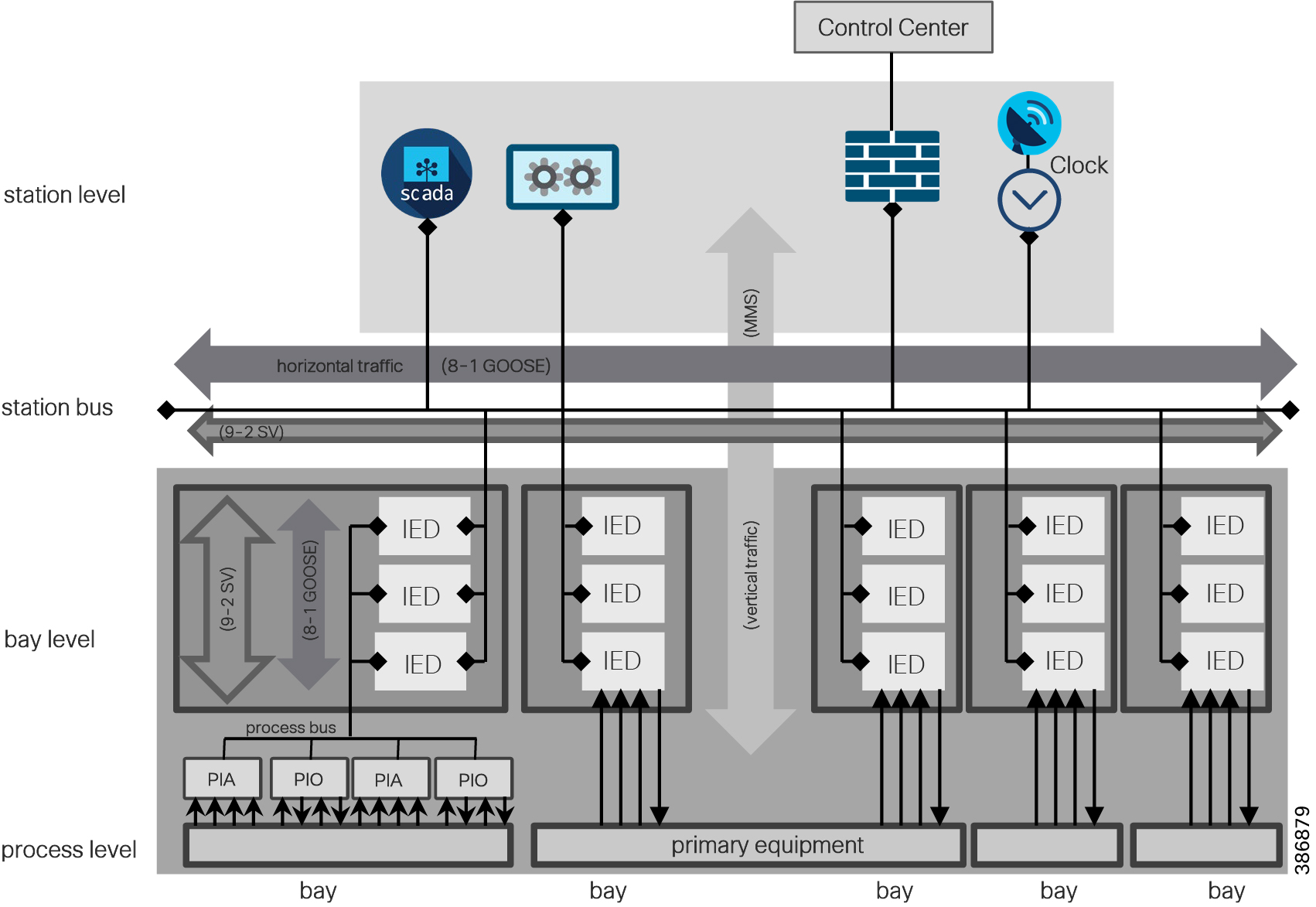
The IEC 61850 modern substation is organized into process level, bay level, and station level. Station buses separate station and bay level. Process bus separates bay and process level are as depicted below.
■![]() The Bus is the ethernet broadcast domain like LAN. Process level is lowest level which hosts transformers, switch equipment, and Merger Unit IEDs.
The Bus is the ethernet broadcast domain like LAN. Process level is lowest level which hosts transformers, switch equipment, and Merger Unit IEDs.
■![]() The Bay is middle level which hosts the bay controller and IEDs for metering, disturbance recorder, and protection.
The Bay is middle level which hosts the bay controller and IEDs for metering, disturbance recorder, and protection.
■![]() The Station level is highest level for local SCADA, engineering computer, clock source, and gateway routers/firewall to connect to centralized control center.
The Station level is highest level for local SCADA, engineering computer, clock source, and gateway routers/firewall to connect to centralized control center.
Figure 11 Ethernet in Substation Automation
The flows and protocols involved in a modern substation is depicted in Figure 12. Traffic flows can be segregated as within the substation (intra-substation) and outside the substation to the control center and to other substations.
Figure 12 Substation Automation Flows
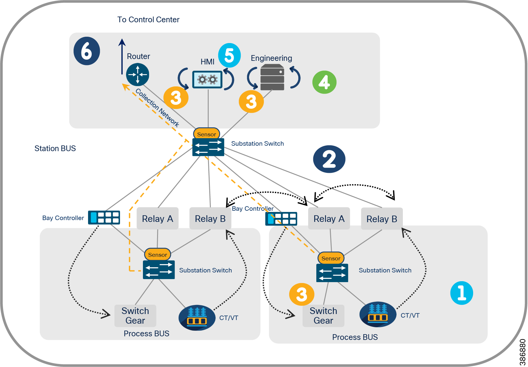
Traffic flows indicated in Figure 12 are described below.
Flow # 1 Instantaneous data and control exchange between primary equipment i.e. Merger unit IED an bay level protection and control IEDs. These flows happen over process bus. Protocol involved are IEC 61850 MMS, GOOSE and Sampled Values.
Flow # 2 Protection and control data exchange between bays over Station bus. GOOSE protocol will normally be used protection message exchanges.
Flow # 3 exchange of protection data and control data between the bay and station Levels IEC 61850 MMS and GOOSE
Flow # 4 Engineering and configuration data exchange between station level and remote engineering PC.
Flow # 5 Monitoring and Supervision exchanges between HMI and Gateway Router
Flow # 6 External to substation data sent to control center via Gateways
Substation Automation Security Requirements
Cybersecurity Requirements of Substation automation system can be grouped as follows
■![]() Group 1. Basic Security Requirements
Group 1. Basic Security Requirements
–![]() Network Segmentation / Electronic Security Perimeter
Network Segmentation / Electronic Security Perimeter
–![]() Data Privacy and Secure connectivity
Data Privacy and Secure connectivity
■![]() Group 2. Enhanced Security Requirements
Group 2. Enhanced Security Requirements
–![]() Intrusion/Threat detection and prevention
Intrusion/Threat detection and prevention
The security requirement group 1 needs to be addressed at first to increase the overall security of the substation automation system. Requirement group 2 can provides additional security measures for those devices which are connected to a network outside the substation.
Cisco Grid Security Architecture for Group 1 requirements are discussed first.
Network Segmentation / Electronic Security Perimeter (ESP)
Requirement: A key aspect of CIP-005-5 is that an ESP must be established for all high-impact and medium-impact Bulk Electrical System (BES) Cyber Systems. These BES Cyber Systems are connected to a network via a routable protocol, regardless of whether the segment containing the BES Cyber System(s) has external connectivity to any other network segment. T
here may be BES Cyber Systems of various impact classifications within a single ESP, but then, all BES Cyber Systems require the highest level of protection corresponding to the BES Cyber System with the highest impact classification within the ESP.
All External Routable Connectivity must be through an identified Electronic Access Point (EAP). Require inbound and outbound access permissions, including the reason for granting access, and deny all other access by default. Have one or more methods for detecting known or suspected malicious communications for both inbound and outbound communications.
Solution: An ESP can be defined by segmentation.
Mechanism to implement segmentation include L2 VLANs, L3 VRFs, Firewall interfaces and/or security contexts, and Security Group Tags (which can provide segmentation regardless of VLAN or IP address assignment). VLANs provide a logical separation of networks and can be done on different layers, most common on layer 2. Firewalls to control inbound and outbound traffic into/from different zones.
The DMZ provides distinct access control to information between two zones. The DMZ is located behind a firewall and spans a semi-trusted zone between the internal and external network. The DMZ contains applications that are accessible from the inside and the outside. All external communication should be routed through a dedicated proxy application in the DMZ.
By creating logical zones within the substation, each can have their own unique security requirements by utilizing the capabilities of the Cisco ISA-3000 industrial firewall In band mode and the Cisco Identity Services Engine for key cybersecurity segment requirements.
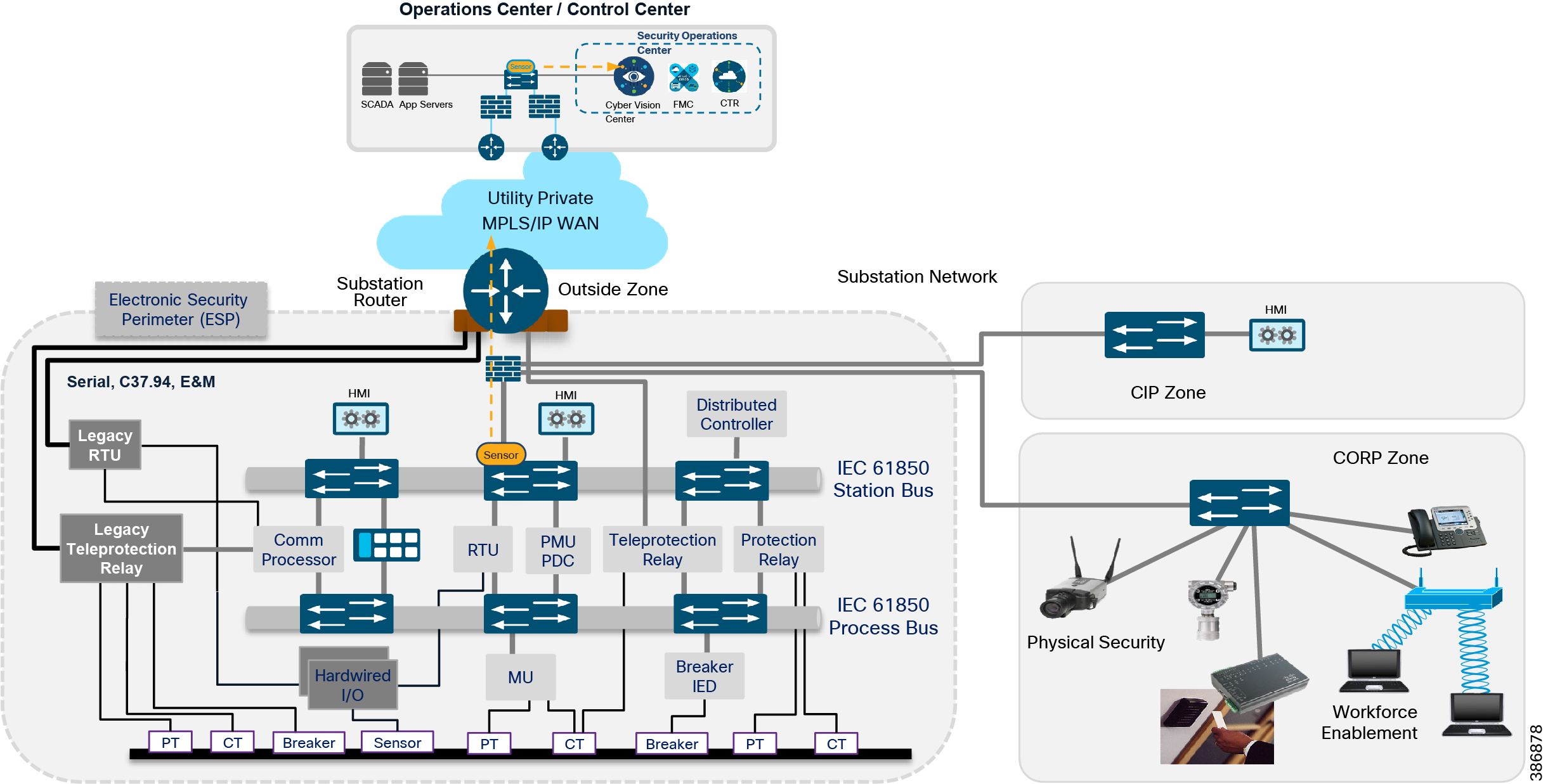
There are four key components of a Substation design: a Corporate Substation (CORPSS) zone, a Critical infrastructure Perimeter (CIP) zone, the Electronic Security Perimeter (ESP) zone, and the Outside zone. Relative firewall security levels are provided to illustrate trust levels between zones.
Figure 13 Segmentation in Substation Automation
For more details about ISA 3K please refer to https://www.cisco.com/c/en/us/td/docs/security/firepower/quick_start/isa3000/isa-3000-gsg/ftd-fmc.html
Electronic Security Perimeter (ESP) zone
This zone contains the active components necessary for proper functioning of the Critical Infrastructure/Smart Grid. The components in this zone are the most valued and trusted resources on the Substation network.
With few exceptions, outbound communications from this portion of the network are significantly restricted. Any communication from this zone to a lower-security zone should leverage a “Pull” model – initiating the connection from the ESP zone. Inbound connections into the ESP zone are discouraged except for business-critical applications.
This zone provides limited network connectivity to industrial components such as IEDs and Protection Relays with direct user-level access for a restricted set of users. These users are typically vetted, full-time employees that require direct substation access for machine maintenance. Depending on the security model used, access to the IEDs and Protection Relays can be restricted to specific, well vetted, and highly audited hosts, not allowing access from personal/corporate laptops, for instance. Outbound connections are highly restricted from this zone.
For more details of ESP zone design refer to the Substation Automation Design and Implementation Guide https://www.cisco.com/c/en/us/td/docs/solutions/Verticals/Utilities/SA/2-3-2/CU-2-3-2-DIG.html
Within the ESP zone further segmentation can be done based on VLAN. These VLANS are listed below.
■![]() OT SCADA VLAN - This VLAN is for SCADA traffic such as Modbus, DNP3, IEC61850 GOOSE.
OT SCADA VLAN - This VLAN is for SCADA traffic such as Modbus, DNP3, IEC61850 GOOSE.
■![]() Network Management VLAN - For all network management traffic. A designated management port is enabled within a VLAN that is used by the management system to communicate with the devices. On the remote Workforce VLAN (Intranet) the remote workforce accesses the substation network using on-site ruggedized PC or wire-connected PC.
Network Management VLAN - For all network management traffic. A designated management port is enabled within a VLAN that is used by the management system to communicate with the devices. On the remote Workforce VLAN (Intranet) the remote workforce accesses the substation network using on-site ruggedized PC or wire-connected PC.
■![]() Remote Workforce VLAN (Internet) - Partner/third party crew is allowed on this VLAN to gain access of the Internet; only outbound traffic is permitted.
Remote Workforce VLAN (Internet) - Partner/third party crew is allowed on this VLAN to gain access of the Internet; only outbound traffic is permitted.
■![]() Physical Security VLAN - Video surveillance traffic, physical access traffic.
Physical Security VLAN - Video surveillance traffic, physical access traffic.
■![]() Black Hole VLAN - As a security best practice, all unused ports are assigned to this VLAN.
Black Hole VLAN - As a security best practice, all unused ports are assigned to this VLAN.
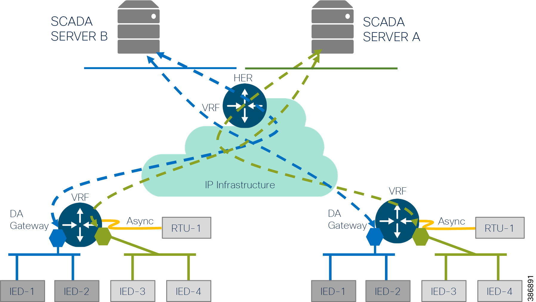
Legacy RTUs are directly connected to the Substation Router via serial RS232/RS485 connections. SCADA traffic from the RTU is sent to the control center and vice versa. Two methods are described below.
■![]() SCADA Gateway or Protocol Translation - For SCADA Gateway/Protocol Translation the serial traffic is converted into IP using the SCADA protocol translation feature on the Substation Router. This traffic is segmented into separate VRFs. Using Cisco FlexVPN, the SCADA traffic is encrypted and sent securely to the control center.
SCADA Gateway or Protocol Translation - For SCADA Gateway/Protocol Translation the serial traffic is converted into IP using the SCADA protocol translation feature on the Substation Router. This traffic is segmented into separate VRFs. Using Cisco FlexVPN, the SCADA traffic is encrypted and sent securely to the control center.
For more details on protocol translation refer to:
https://www.cisco.com/c/en/us/td/docs/routers/connectedgrid/cgr2010/software/15_3_2_t/sca_pro_cgr2010.html
■![]() Raw Sockets - Raw Socket is a method for transporting serial data through an IP network. The feature can be used to transport Supervisory Control and Data Acquisition (SCADA) data from Remote Terminal Units (RTUs). This feature is enabled on the substation router. Configure existing pinholes on the firewall on the transit to allow the raw socket UDP/TCP traffic. The VRF-aware Raw Socket Transport feature enables you to isolate Raw Socket traffic using a VRF for efficient management and control of serial data.
Raw Sockets - Raw Socket is a method for transporting serial data through an IP network. The feature can be used to transport Supervisory Control and Data Acquisition (SCADA) data from Remote Terminal Units (RTUs). This feature is enabled on the substation router. Configure existing pinholes on the firewall on the transit to allow the raw socket UDP/TCP traffic. The VRF-aware Raw Socket Transport feature enables you to isolate Raw Socket traffic using a VRF for efficient management and control of serial data.
For more details on raw socket refer to:
https://www.cisco.com/c/en/us/td/docs/routers/connectedgrid/cgr2010/software/15_2_4_m/raw_socket.html#48381
For more details on Asynchronous serial interfaces on IOT routers refer to:
https://www.cisco.com/c/en/us/products/collateral/routers/829-industrial-router/white-paper-c11-743674.html#2Usecases
Corporate Substation (CORPSS) zone
This zone is a natural extension to the corporate/enterprise “General Purpose” network. Traffic from this zone can only access other corporate assets directly leaving through the Outside zone. Access to the other zones (CIP and ESP) requires additional credentials and is subject to access restrictions. All employees can leverage this zone for basic connectivity to business resources including email, file shares, and general access to the Internet via the Outside zone.
Critical Infrastructure Perimeter (CIP) zone
This zone is a “DMZ” for the substation. It is “semi-trusted” and has a Firewall security level between the Corporate Substation zone and the ESP zone. This zone allows proxied user-level access between both the Corporate Substation and ESP zones, leveraging an information security (InfoSec) hardened Bastion host. Other support infrastructure may also exist in this zone -- such as a Secure Policy Server such as Cisco ISE or ACS, Network Services, and/or a user management server such as LDAP or Active Directory (AD).
Inbound connectivity to this zone is provided via a Remote Access VPN client or via a Courtesy port within the CIP zone switch network. The Courtesy Port will be discussed in a later section of this document. As a user connects into the CIP zone, the user level of access is restricted to allow connectivity to ONLY the Bastion host. This Bastion host will have predefined levels of access inbound to the ESP zone and outbound towards the corporate network. All user-level connectivity between the ESP and Corporate Substation networks is proxied via this Bastion host. Access to and from other resources within the CIP zone are significantly restricted to ensure the integrity of these resources and their interactions with the ESP zone.
Any employee or contractor that has the proper credentials can operate the network and security resources within this zone. Membership in the appropriate Active Directory (AD) group can be leveraged to restrict Courtesy Port or Remote Access authentication and authorization.
The Outside zone connects the Substation topology to the rest of the infrastructure - whether the infrastructure is owned by the Utility/Corporation or provided by a 3rd party Service Provider.
This zone is untrusted. Most of the asset security postures within this outside zone are not in the control of the Utility/Corporation.
The traffic that is allowed to traverse this interface should be encrypted, authenticated, and/or originally initiated from the inside zones (ESP, CIP, and CORPSS) of the ISA3000 firewall. The AnyConnect Remote Access endpoints can authenticate to the Outside interface to gain access to the CIP and ESP zones.
This zone is considered outside the Substation architecture; protection of this zone is varied and relies solely on the protections provided by the WAN infrastructure.
Between the substation and utility facility, WAN traffic is also segmented by one-to-one mapping with VLAN inbound/outbound traffic. Multiprotocol Label Switching (MPLS) VPN is recommended for the communication between the substations and utility facility, and the following VRFs are required for MPLS VPN:
Access Control
The requirement to establish identity is to ensure that only authorized personnel are accessing the network and valid devices are part of the grid network.
Authenticating and authorizing field technicians or operations center staff must be complete before they can view or configure devices. Role-based Access Control is used to track any changes made by technicians. For engineer/technician devices that need to access the substation, only 802.1x authenticated users should be permitted access.
For authenticating users and endpoints connected to the substation / control center networks, use various methods such as AAA and/or endpoint certificates. MAC Authentication Bypass (MAB) is used for endpoints that do not have 802.1x supplicant.
For more details on 802.1x port-based authentication refer to: https://www.cisco.com/c/en/us/td/docs/switches/lan/cisco_ie4010/software/release/15-2_4_EC/configuration/guide/scg-ie4010_5000/sw8021x.html
For more details on using Cisco ISE as a Radius server refer to: https://www.cisco.com/c/en/us/support/docs/security/identity-services-engine/215525-use-radius-for-device-administration-wit.html
For limiting the number of devices that can be connected to the port, and to prevent rogue/unknown devices to connect to the network. To protect the substation LAN from being exploited, unused ports of all LAN switches at the substation must be shut down by default as defined in NERC-CIP. In-use ports must be explicitly enabled. For those ports that are enabled, port security should be configured to protect the network from LAN-based attacks. This feature limits the number of MAC addresses that can connect to a switch and ensures that only approved MAC addresses are able to access the switch. Port security prevents MAC address flooding and ensures that only approved users can log onto the network.
The following security policy applies to port security configuration:
■![]() The maximum number of secure MAC addresses for a port is one (1).
The maximum number of secure MAC addresses for a port is one (1).
■![]() For IED or other IP-enabled control devices, specify a static MAC address.
For IED or other IP-enabled control devices, specify a static MAC address.
■![]() If IED MAC is unknown, specify sticky port security.
If IED MAC is unknown, specify sticky port security.
■![]() For onsite engineer/technician device access in the substation, only authenticated users are permitted access via the designated user access port (802.1x).
For onsite engineer/technician device access in the substation, only authenticated users are permitted access via the designated user access port (802.1x).
To prevent DoS attacks such as MAC attacks or Layer-2 Protocol Data Unit (PDU) attacks, the following key Cisco solution differentiators Layer-2 security mechanisms should be enabled:
■![]() DHCP Snooping — With this feature enabled, a switchport forwards DHCP requests only on untrusted access ports and drops all other types of DHCP traffic. DHCP snooping eliminates rogue devices from behaving as the DHCP server. For substation LAN switches, the uplink port should be the trusted port as the DHCP server is deployed at the datacenter, whereas the client access ports are untrusted.
DHCP Snooping — With this feature enabled, a switchport forwards DHCP requests only on untrusted access ports and drops all other types of DHCP traffic. DHCP snooping eliminates rogue devices from behaving as the DHCP server. For substation LAN switches, the uplink port should be the trusted port as the DHCP server is deployed at the datacenter, whereas the client access ports are untrusted.
■![]() Dynamic Address Resolution Protocol (ARP) Inspection (DAI) — This feature maintains a binding table containing IP and MAC address associations dynamically populated using DHCP snooping. This feature ensures the integrity of user and default gateway information such that traffic cannot be captured. ARP spoofing or ARP poisoning attacks are mitigated through this feature.
Dynamic Address Resolution Protocol (ARP) Inspection (DAI) — This feature maintains a binding table containing IP and MAC address associations dynamically populated using DHCP snooping. This feature ensures the integrity of user and default gateway information such that traffic cannot be captured. ARP spoofing or ARP poisoning attacks are mitigated through this feature.
■![]() IP Source Guard — This feature automatically configures a port ACL for an IP address and adds a MAC address to the port security list for the port. DHCP snooping uses the port ACL defined by IP Source Guard to assist in building the DHCP binding table. When the ACL or MAC entry lease expires, DHCP Snooping removes these entries from the table. These two features working together snooping of data or anonymous launching of attacks.
IP Source Guard — This feature automatically configures a port ACL for an IP address and adds a MAC address to the port security list for the port. DHCP snooping uses the port ACL defined by IP Source Guard to assist in building the DHCP binding table. When the ACL or MAC entry lease expires, DHCP Snooping removes these entries from the table. These two features working together snooping of data or anonymous launching of attacks.
To prevent a malicious user taking up the bandwidth and starving critical application traffic, or to prevent data traffic from the contractor occupying the network and affecting the control traffic, use the following techniques.
Rate limiters can limit traffic per VLAN, port, or user to mitigate the impact of packet-blasting worms and limit the amount of traffic a user can send onto the network employ rate-limiting using either traffic policing or shaping functions.
Modbus protocol operates in a well-defined port number 502. Quality of service (QoS) can be configured on the substation switches to rate-limit for MODBUS TCP traffic.
Data Privacy and Secure Connectivity
Interactions between the substation automation system, corporate networks and the outside world are usually handled on the station level. This means that ensuring a high level of security on the station level is vital to the security of the SA system itself. Firewalls and VPN technology should protect the substation automation system. All communication from the outside world to a substation should be protected by using a firewall and/or VPN-enabled communication.
Data security will be applied for both transmitted and stored information. Data encryption of stored information like engineering and control data or backup data. This may be done by using hard disc encryption tools at the lower layer or database encryption tools providing in combination with access control to the stored information.
Deploy traffic encryption using:
■![]() Security protocol options of the communication protocols used. For example, IEC 62351, secure DNP3, and so on.
Security protocol options of the communication protocols used. For example, IEC 62351, secure DNP3, and so on.
■![]() Security protocols to protect individual connections (TLS, DTLS, IPSec).
Security protocols to protect individual connections (TLS, DTLS, IPSec).
■![]() Separate (additional) security appliances like VPN gateways. This approach is typically transparent to the other components. For example, it can be applied between a substation router and the control center firewall. It only protects the traffic between the VPN gateways, not on the entire communication path.
Separate (additional) security appliances like VPN gateways. This approach is typically transparent to the other components. For example, it can be applied between a substation router and the control center firewall. It only protects the traffic between the VPN gateways, not on the entire communication path.
Traffic exiting out of the substation to the Control Center or other control stations over public infrastructure must be encrypted. Grid Security solution architecture recommends Cisco FlexVPN technology for network encryption. A FlexVPN Tunnel is formed between substation router and control center headend router. Interesting traffic like SCADA and Substation IEDs must be encrypted. Multiple substation routers from the spoke and Headend router will act as FlexVPN spokes.
Network Availability
Network Availability is one of key requirement of Substation Automation Systems. Redundancy in the network protects against failures caused by network components failures and important design for cater to network availability. Network redundancy is a basic requirement for automation systems since it ensures a high degree of network reliability. In redundant network topologies, a backup path is established for use when part of the network becomes unavailable.
Redundancy in substation can be categorized into IED Level, bus level, Substation firewall and Substation Router level.
IEDs, such as protective relays, with two network interfaces support redundancy by sending the same traffic simultaneously through both interfaces. This type of redundancy is also known as parallel redundancy and it offers zero-time recovery, essentially not interrupting the traffic at all.
The two parallel redundancy protocols are Parallel Redundancy Protocol (PRP) and High-availability Seamless Redundancy (HSR) Both PRP and HSR provide redundancy at the Ethernet layer of the TCP/IP stack. Redundancy and zero-time recovery are beneficial for protocols, such as GOOSE, which requires real-time delivery.
For more details of Station Bus and Process Bus redundancy design aspects refer to following Substation Automation DIG:
https://www.cisco.com/c/en/us/td/docs/solutions/Verticals/Utilities/SA/2-3-2/CU-2-3-2-DIG.html
Auditability and Logging
Group 1 basic security requirements and solution for authorization, authentication, encryption, and access control mechanisms lays the strong security foundation for substation automation. The only thing left is the visibility and ability to monitor what happens in the system, known as auditability. To be able to monitor the system we need the discrete actions in the system to be generated as events. These events are called security events and are not be confused with what we typically call process events.
The NERC CIP requirements for security event monitoring are to:
■![]() Detect successful login attempts
Detect successful login attempts
■![]() Detect failed access attempts and failed login attempt
Detect failed access attempts and failed login attempt
■![]() Generate alerts for about mentioned security events and changes in configurations, firmware changes, password changes
Generate alerts for about mentioned security events and changes in configurations, firmware changes, password changes
■![]() Retain event logs for 90 consecutive calendar days
Retain event logs for 90 consecutive calendar days
Cisco encourages the use of centralized management for logging and events. For Substation Switches and Routes syslog feature can be turned on to send the logs to syslog server. Another advanced feature is Flexibility NetFlow. Flexible NetFlow (FNF) is an integral part of Cisco IOS Software that collects and measures data, allowing all routers or switches in the network to become a source of telemetry and a monitoring device. FNF can be used to monitor:
■![]() Application and network usage
Application and network usage
■![]() Network productivity and utilization of network resources
Network productivity and utilization of network resources
■![]() The impact of changes to the network
The impact of changes to the network
■![]() Network anomaly and security vulnerabilities
Network anomaly and security vulnerabilities
■![]() Long term compliance producing business process and audit trails
Long term compliance producing business process and audit trails
■![]() Understand who, what, when, where, and how network traffic is flowing
Understand who, what, when, where, and how network traffic is flowing
Enabling NetFlow on switches and routers involves three elements: a flow record, a flow exporter, and a flow monitor. After you have configured all three components, apply the flow monitor to the interface connected to the IED.
A flow record defines the information that will be gathered by the NetFlow process, such as packets in the flow and the types of counters gathered per flow. Custom flow records specify a series of match and collect commands that tell the Cisco device which fields to include in the outgoing NetFlow record.
The match fields are the key fields, meaning that they are used to determine the uniqueness of the flow. The collect fields are extra information that is included in the record to provide more detail to the collector for reporting and analysis. When you create a flow record, you are telling the device to show all of the flow data traffic that enters (ingress) or leaves (egress) the device.
The flow exporter defines where and how to send the NetFlow (flow records). A flow exporter defines a flow collector IP address and port as the destination.
A flow monitor describes the NetFlow cache or the information stored in the cache. Additionally, the flow monitor links together the flow record and the flow exporter. The flow monitor includes various cache characteristics such as the timers for exporting, the size of the cache, and, if required, the packet sampling rate (Sampled NetFlow / sFlow). As network traffic traverses the Cisco device, flows are continuously created and tracked. As the flows expire, they are exported from the NetFlow cache to the flow collector. A flow is ready for export when it is inactive for a certain time (for example, no new packets received for the flow); or if the flow is long lived (active) and lasts greater than the active timer (for example, a long FTP download). There are timers to determine whether a flow is inactive, or a flow is long lived. Once the flow monitors have been created, they can be applied to the various device interfaces. Depending on the topology of the network and the flow information desired to track, the input, output, or both monitors can be applied.
For more details of Syslog and FNF refer to the following links.
https://www.cisco.com/c/en/us/td/docs/switches/lan/cisco_ie4010/software/release/15-2_4_EC/configuration/guide/scg-ie4010_5000/swlog.html
https://www.cisco.com/c/en/us/td/docs/switches/connectedgrid/cg-switch-sw-master/software/release/notes/rn-15-2-6e1.html
Audit and logging capabilities for substation firewall (ISA 3K) will be performed using Firepower Management Center (FMC). FMC System dashboards provide you with at-a-glance views of current system status, including data about the events collected and generated by the system. The System Log (syslog) page provides you with system log information for the appliance.
You can audit activity on your system in the following two ways:
■![]() The appliances that are part of the Firepower System generate an audit record for each user interaction with the web interface, and record system status messages in the system log. For more details about FMC refer to the link below.
The appliances that are part of the Firepower System generate an audit record for each user interaction with the web interface, and record system status messages in the system log. For more details about FMC refer to the link below.
https://www.cisco.com/c/en/us/td/docs/security/firepower/660/configuration/guide/fpmc-config-guide-v66/working_with_intrusion_events.html
■![]() Other Cyber assets (non-Cisco infra) require logging enabled on each asset, and perhaps SNMP traps sent to a SIEM for centralized collection.
Other Cyber assets (non-Cisco infra) require logging enabled on each asset, and perhaps SNMP traps sent to a SIEM for centralized collection.
Intrusion detection and prevention
Deep packet inspection of SCADA traffic in the substation automation system can significantly improve the security and reliability of the system. A deep packet inspection device such as a substation firewall should have options to inspect header, payload to filter based on functions, commands, and data.
Cisco ISA 3000 Substation Firewalls have the capability to perform IDS and IPS functionality for Modbus and DNP3 SCADA protocols.
The Intrusion detection capabilities of the ISA 3000 is in the feature called the SCADA preprocessor. By enabling this feature, the ISA3000 can perform application identification beyond traditional port numbers and by inspecting entire frame to recognize the protocol/application. Post detection of the ISA 3000 can generate an event to the Firepower Management Center or can drop the packets if it is inline deployed.
Modbus preprocessor feature has capabilities to perform the following IDS operations:
■![]() Generates an event when the length in the Modbus header does not match the length required by the Modbus function code. Each Modbus function has an expected format for requests and responses. If the length of the message does not match the expected format, this event is generated.
Generates an event when the length in the Modbus header does not match the length required by the Modbus function code. Each Modbus function has an expected format for requests and responses. If the length of the message does not match the expected format, this event is generated.
■![]() Generates an event when the preprocessor detects a reserved Modbus function code.
Generates an event when the preprocessor detects a reserved Modbus function code.
■![]() Generates an event when the Modbus protocol ID is non-zero. The protocol ID field is used for multiplexing other protocols with Modbus. Because the preprocessor does not process these other protocols, this event is generated instead.
Generates an event when the Modbus protocol ID is non-zero. The protocol ID field is used for multiplexing other protocols with Modbus. Because the preprocessor does not process these other protocols, this event is generated instead.
The DNP3 preprocessor feature has capabilities to perform following IDS operations:
■![]() When Log bad CRC is enabled, it generates an event when the preprocessor detects a link layer frame with an invalid checksum.
When Log bad CRC is enabled, it generates an event when the preprocessor detects a link layer frame with an invalid checksum.
■![]() Generates an event and blocks the packet when the preprocessor detects a DNP3 link layer frame with an invalid length.
Generates an event and blocks the packet when the preprocessor detects a DNP3 link layer frame with an invalid length.
■![]() Generates an event and blocks the packet during reassembly when the preprocessor detects a transport layer segment with an invalid sequence number.
Generates an event and blocks the packet during reassembly when the preprocessor detects a transport layer segment with an invalid sequence number.
■![]() Generates an event when the DNP3 reassembly buffer is cleared before a complete fragment can be reassembled. This happens when a segment carrying the FIR flag appears after other segments have been queued.
Generates an event when the DNP3 reassembly buffer is cleared before a complete fragment can be reassembled. This happens when a segment carrying the FIR flag appears after other segments have been queued.
■![]() Generates an event when the preprocessor detects a DNP3 link layer frame that uses a reserved address.
Generates an event when the preprocessor detects a DNP3 link layer frame that uses a reserved address.
■![]() Generates an event when the preprocessor detects a DNP3 request or response that uses a reserved function code.
Generates an event when the preprocessor detects a DNP3 request or response that uses a reserved function code.
The Intrusion Protection function on the ISA 3000 is used to detect individual SCADA commands like Modbus Read Coil register or Write Holding register using the protocol-specific application identifier feature. This feature provides a granular control of SCADA commands. Intrusion policies are defined sets of intrusion detection and prevention configurations that inspect traffic for security violations and, in inline deployments, can block or alter malicious traffic. Intrusion policies are invoked by your access control policy and are the system’s last line of defense before traffic is allowed to its destination.
At the heart of each intrusion policy are the intrusion rules. An enabled rule causes the system to generate intrusion events for (and optionally block) traffic matching the rule. Disabling a rule stops processing of the rule.
The Modbus IPS rule options cover the entire Modbus packet.
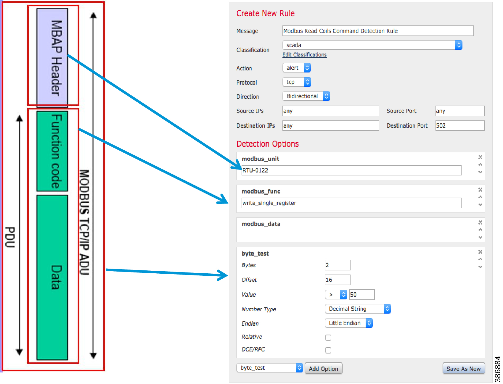
Modbus unit ranges from 0 to 255.
Modbus and DNP3 Functional codes are provided in Appendix B. IPS rules can be framed based on deployment scenarios using supported function codes. Application Identifiers are also supported for IEC 60870-5-104 and IEC 61850 MMS Utility protocols.
OT visibility for assets and SCADA flows are covered are discussed in Chapter 5 of this guide.
Chapter 4 Grid Security Design for Distribution Automation
Distribution Automation
Distribution Automation (DA) refers to the monitoring and control of devices located on the distribution feeders, such as line reclosers, load break switches, sectionalizers, capacitor banks and line regulators, and devices located in the distribution substation. DA is an overlay network deployed in parallel to the distribution feeder. It enables two-way communication between controllers used in the distribution feeder and the intelligence application that resides in the Utility Control Center or Secondary Substation for improving grid reliability, availability, and control.
Distribution Automation Use cases
Distribution Automation (DA) use cases can be classified as vertical and horizontal as shown in Figure 17. Horizontal use cases lay the foundation for transporting the vertical use cases.
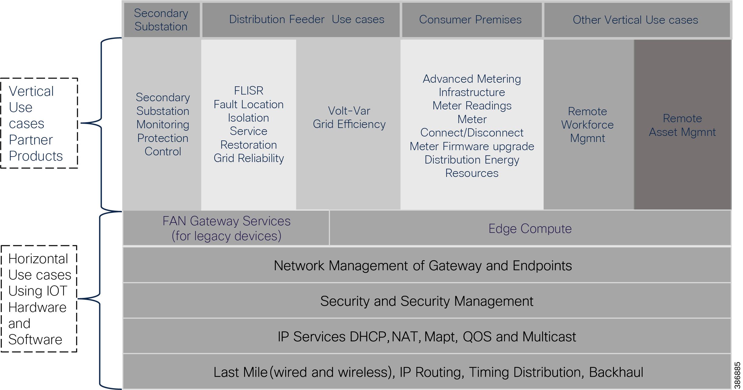
Vertical use cases can be sub-classified as:
■![]() Secondary Substation use cases
Secondary Substation use cases
■![]() Other use cases, such as Remote workforce and Asset Management
Other use cases, such as Remote workforce and Asset Management
DA Solution Architecture
Cisco has two variations of a solution offering for DA. The solution is known as Field Area Network Solution. The first solution is based on Cellular technology called FAN Distribution Automation Secondary Substation, and the second solution is based on Cisco Resilient Mesh based solution called Feeder Automation.
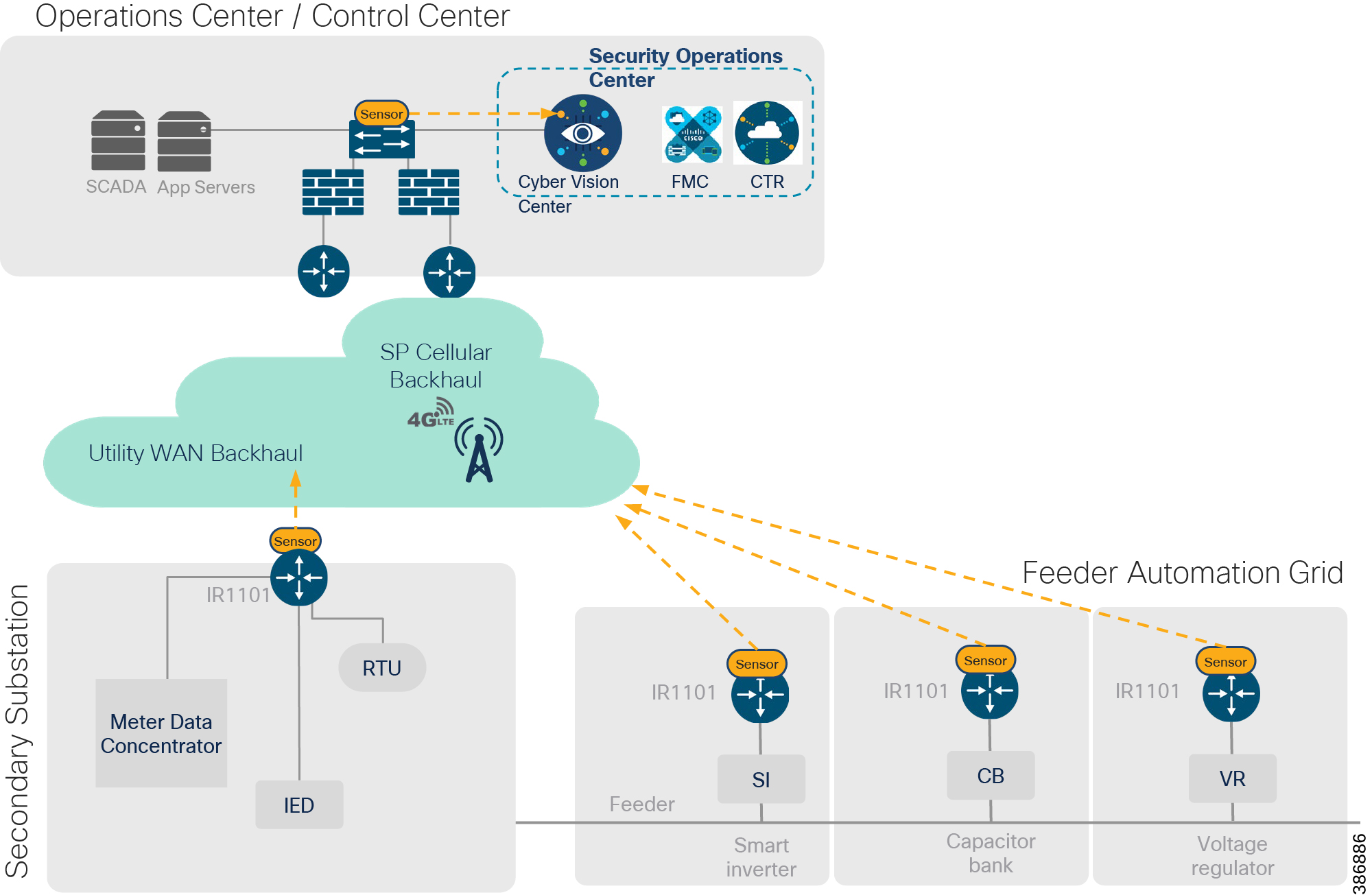
Secondary Substation Solution Architecture
DA Secondary Substation Architecture is a two-tier centralized Architecture depicted in Figure 18. The WAN tier is where the cellular backhaul connects distribution substation/grid to the centralized control center. The Cisco IR1101 can be positioned as secondary substation router (SSR) or Distribution Automation (DA) Gateway for feeder use cases. The SSR and DA Gateways in turn connect to various OT devices like RTU, IED, Meter Data concentrators, Capacitor Bank controllers and Voltage Regulator controller.
Figure 18 Distribution Substation
Feeder Automation Solution Architecture
The Cisco Distribution Automation - Feeder Automation Design Guide provides a comprehensive explanation of the entire end-to-end Cisco Smart Grid Field Area Network (FAN) solution design, which was developed for the Utility Industry in the Americas region and leverages the license free spectrum: ISM band 902 - 928 MHz for last mile connectivity of the Distribution Network Grid devices. This design targets implementations that will use the customer's Substation Private WAN as backhaul for the Resilient Mesh Network to transport data from grid devices in the field to the Control and Operation Centers.
For more details on DA Secondary Substation and Feeder Automation design, use case and architecture refer to the CVD links below.
htps://www.cisco.com/c/en/us/td/docs/solutions/Verticals/Distributed-Automation/Secondary-Substation/DG/DA-SS-DG.html
https://www.cisco.com/c/en/us/td/docs/solutions/Verticals/Distributed-Automation/Feeder-Automation/DG/DA-FA-DG.html
DA use case application flow is bidirectional. The DA Use case classification is shown below.
The Grid Security Solution Architecture provides design consideration for first two application flows.
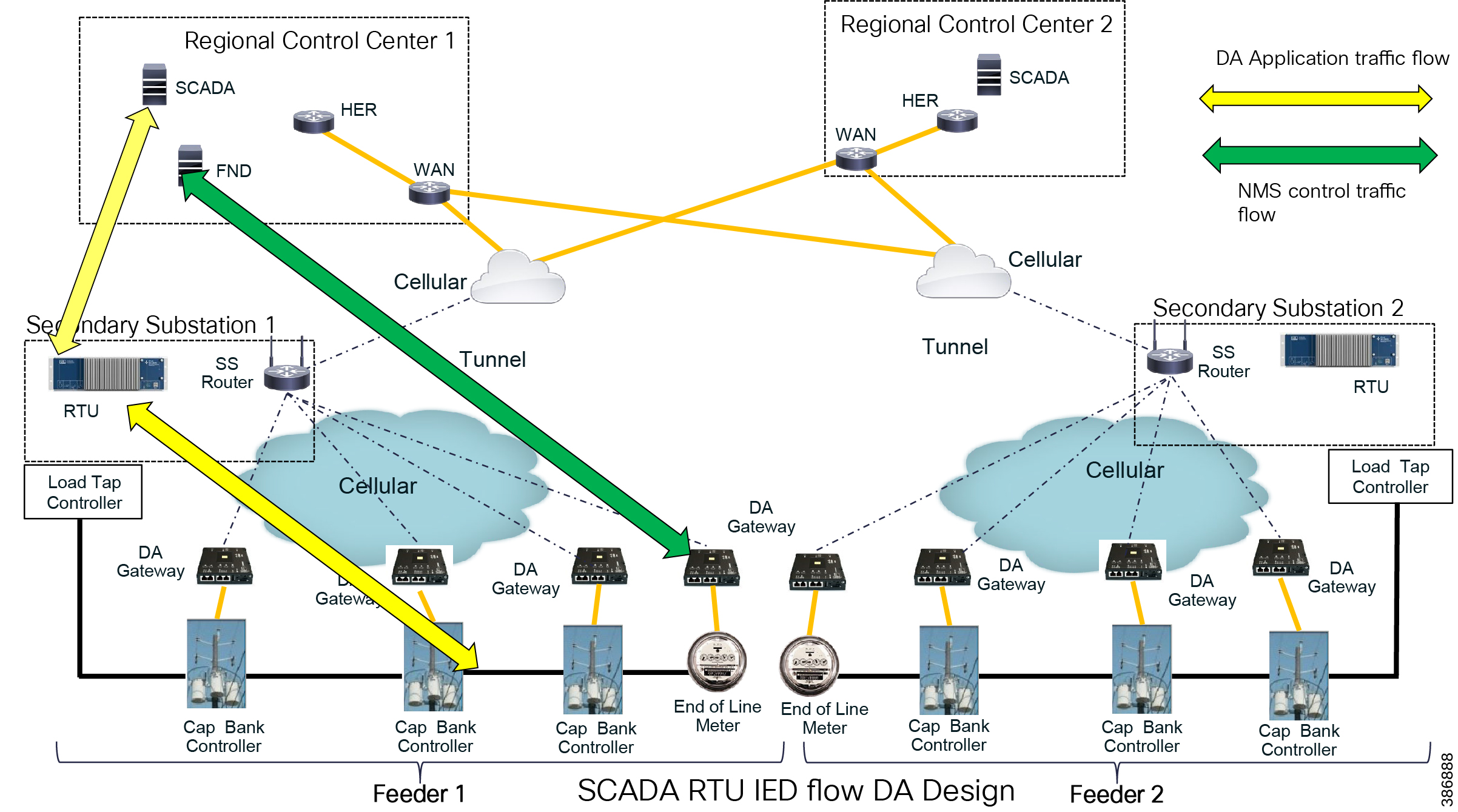
The SCADA bidirectional traffic flow from field IEDs to SCADA in the control center is via RTU, which is in the Secondary Substation. Application traffic is depicted by the yellow arrow in Figure 20. The solution design for this application flow is as follows:
■![]() DA Gateways, which are installed 1:1 with the controllers and last mile connectivity, have Ethernet or serial connectivity.
DA Gateways, which are installed 1:1 with the controllers and last mile connectivity, have Ethernet or serial connectivity.
■![]() DA Gateways have public WAN connectivity; in most deployment cases, it is cellular backhaul.
DA Gateways have public WAN connectivity; in most deployment cases, it is cellular backhaul.
■![]() Application traffic is encrypted using FlexVPN. In this architecture, tunnels from the DA Gateways are terminated on the SSR.
Application traffic is encrypted using FlexVPN. In this architecture, tunnels from the DA Gateways are terminated on the SSR.
■![]() The WAN IP address of the Secondary Substation is a static (fixed IP) address.
The WAN IP address of the Secondary Substation is a static (fixed IP) address.
■![]() The SSRs route traffic from the IEDs to the RTU, which is co-located.
The SSRs route traffic from the IEDs to the RTU, which is co-located.
■![]() The RTU processes this application traffic as unsolicited reporting or response to poll/control command.
The RTU processes this application traffic as unsolicited reporting or response to poll/control command.
■![]() The RTU sends the DA application traffic to the SCADA application in the control center.
The RTU sends the DA application traffic to the SCADA application in the control center.
■![]() To transport this application, the SSR uses a secure encrypted FlexVPN tunnel to the HER which resides in the control center.
To transport this application, the SSR uses a secure encrypted FlexVPN tunnel to the HER which resides in the control center.
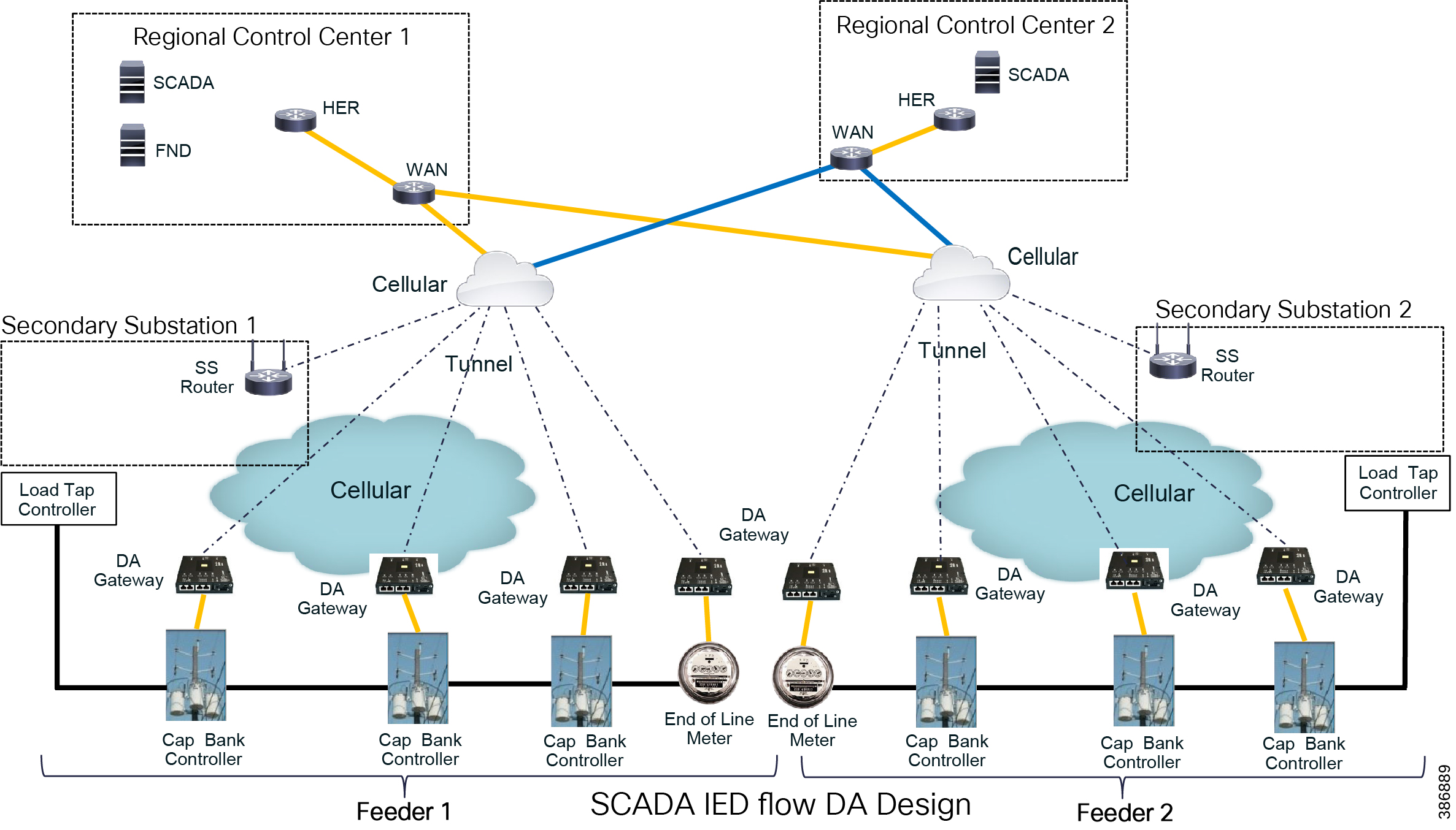
IEDs can directly communicate with the centralized SCADA. DA Gateways and SSRs connect directly to HER in the regional control center via public WAN connectivity. For redundancy design, DA Gateways can have two active/active tunnels to two different regional control centers. DA application traffic and NMS control traffic can flow in the same FlexVPN tunnel.
Distribution Automation Security Requirements
–![]() Authentication, Authorization & Accounting
Authentication, Authorization & Accounting
■![]() Data Confidentiality and Data Privacy
Data Confidentiality and Data Privacy
–![]() Security Connectivity and Encryption (VPN)
Security Connectivity and Encryption (VPN)
■![]() Threat Detection and Mitigation
Threat Detection and Mitigation
–![]() Intrusion Prevention with SCADA signatures
Intrusion Prevention with SCADA signatures
Access Control
To ensure that only authorized personnel are accessing the network and valid devices are part of the grid network: Use Role-Based Access Control with username and password, X.509 certificate-based identities; RADIUS and TACACS+ protocols for Authentication, Authorization and Accounting (AAA) for users and devices; Network Admission Control (NAC). Include these techniques:
■![]() Authenticating and authorizing field technicians or operations center staff before they can view or configure devices, track changes made (RBAC).
Authenticating and authorizing field technicians or operations center staff before they can view or configure devices, track changes made (RBAC).
■![]() Authenticating every device and application connected to the DA network – routers, switches, servers, workstations, IEDs, reclosers.
Authenticating every device and application connected to the DA network – routers, switches, servers, workstations, IEDs, reclosers.
■![]() DA Gateways or SSR are authenticated using PKI process. The detail process is explained in the FAN Headend CVD.
DA Gateways or SSR are authenticated using PKI process. The detail process is explained in the FAN Headend CVD.
For details refer to https://salesconnect.cisco.com/open.html?c=da249429-ec79-49fc-9471-0ec859e83872
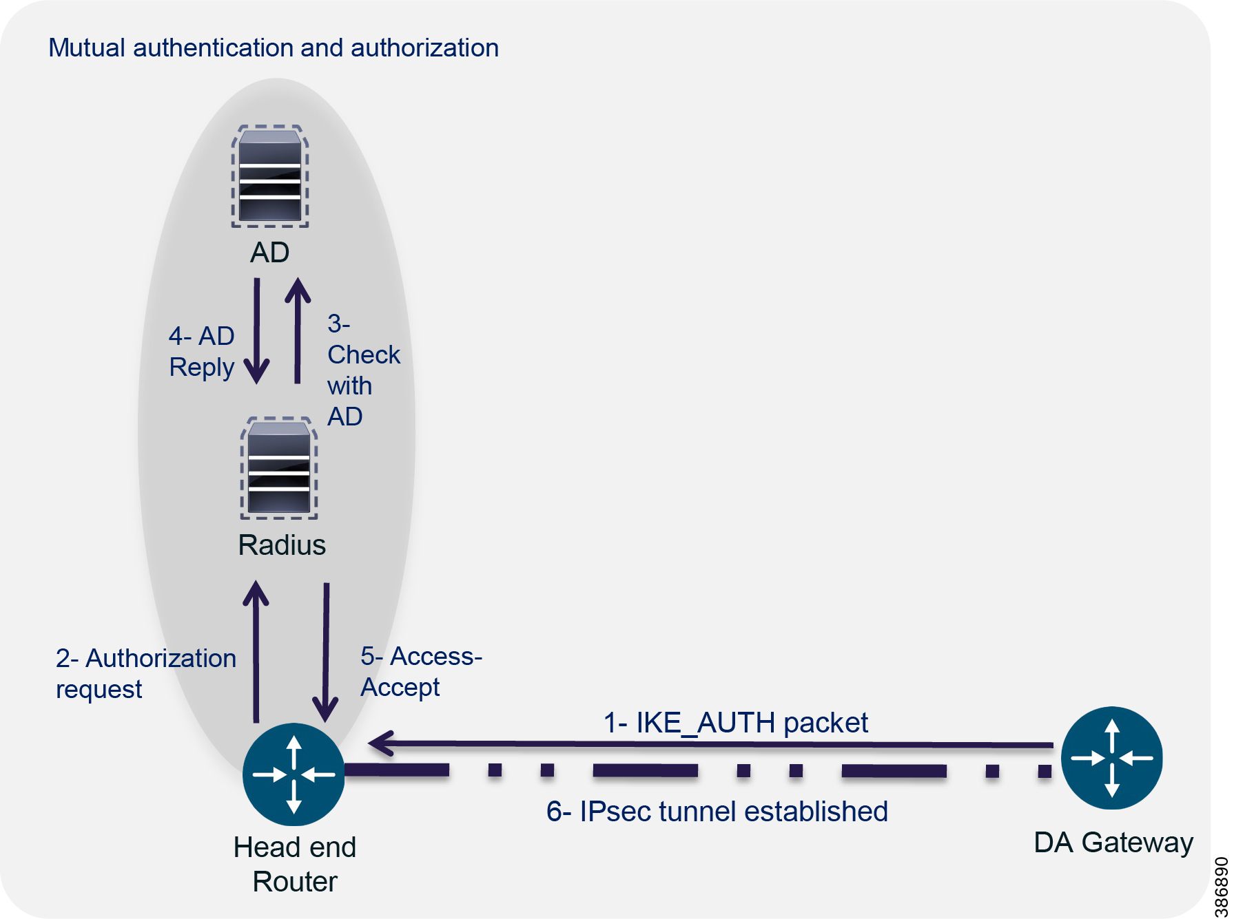
■![]() Mutually authenticating DA Routers and Headend Router – relying on strong certificate-based identities as explained in Figure 22 where authenticity of DA Gateway router is verified before encryption IPSEC tunnel formation.
Mutually authenticating DA Routers and Headend Router – relying on strong certificate-based identities as explained in Figure 22 where authenticity of DA Gateway router is verified before encryption IPSEC tunnel formation.
Figure 22 IPSEC Tunnel formation
Data Confidentiality and Data Privacy
To ensure data privacy and data integrity for both customer data and technical data belonging to the utility use X.509 Certificates, IPSec with flexible VPN architectures, link-layer and application layer encryption mechanisms, scalable crypto key management. Include these techniques:
■![]() Secure generation and storage of encryption keys on all devices – meters, routers, application servers such as SCADA, AMI Head End, NMS.
Secure generation and storage of encryption keys on all devices – meters, routers, application servers such as SCADA, AMI Head End, NMS.
■![]() Encrypting all data traversing using IPSEC (FlexVPN) over public networks between distribution substations/DA Gateways and control centers.
Encrypting all data traversing using IPSEC (FlexVPN) over public networks between distribution substations/DA Gateways and control centers.
■![]() Link-layer (mesh) encryption of data from meters to the field area routers and network layer encryption from FAR to AMI Head End (IPSEC) for AMI deployment.
Link-layer (mesh) encryption of data from meters to the field area routers and network layer encryption from FAR to AMI Head End (IPSEC) for AMI deployment.
■![]() (Optional) Application layer encryption of SCADA protocols like DNP over SSL/TLS.
(Optional) Application layer encryption of SCADA protocols like DNP over SSL/TLS.
For details about FlexVPN design refer to https://www.cisco.com/c/en/us/td/docs/solutions/Verticals/Distributed-Automation/Secondary-Substation/DG/DA-SS-DG.html
Threat Detection and Mitigation
To protect critical assets against cyber-attacks and insider threats use VRF and VLAN, access lists, Firewall and Intrusion Prevention (on routers and appliances), device logs, and SIEM. Employ the following techniques:
■![]() Logically segment and separate traffic – AMI as opposed to DA
Logically segment and separate traffic – AMI as opposed to DA
■![]() Use access lists to filter traffic between segments/zones
Use access lists to filter traffic between segments/zones
■![]() Deploy firewalls to protect critical assets and create a layered network based on stricter restrictions with increasing security levels
Deploy firewalls to protect critical assets and create a layered network based on stricter restrictions with increasing security levels
■![]() Detect network intrusions through use of IPS at critical points in the network. (Optional) customize with SCADA IPS signatures
Detect network intrusions through use of IPS at critical points in the network. (Optional) customize with SCADA IPS signatures
■![]() Collect logs across devices, meters, application and correlate with IPS events to identify security incidents with SIEM, take mitigation steps
Collect logs across devices, meters, application and correlate with IPS events to identify security incidents with SIEM, take mitigation steps
Segmentation of DA Services using VRF Lite
A simple but powerful network security technique is to logically separate different functional elements that should never be communicating with each other. For example, in the distribution grid, smart meters should not be communicating to DA devices and vice versa. Similarly, traffic originating from field technicians should be logically separated from AMI and DA traffic. The Cisco DA Gateways and Secondary Substation Router architecture supports tools such as Virtual Routing & Forwarding (VRFs), VLANs or Generic Routing Encapsulation (GRE) to achieve network segmentation.
VRF Lite provides traffic isolation by using input interfaces to distinguish routes for different VLANs and forms virtual packet-forwarding tables by associating one or more Layer 3 interfaces with each VRF. Interfaces in a VRF can be either physical, such as Ethernet ports, or logical, such as VLAN SVIs and loopback interfaces, but a Layer 3 interface cannot belong to more than one VRF at any time.
For design and implementation details about segmenting regular SCADA vs Legacy SCADA Services using VRF Lite feature, refer to:
https://www.cisco.com/c/en/us/td/docs/routers/connectedgrid/cgr1000/ios/software/15_4_1_cg/vrf_cgr1000.html
Cisco DA Gateway and Secondary Substation Router has the capability to perform NAT as well as Port Address Translation. Using NAT/PAT in combination with zone-based firewall only desired application ports can be opened. This enhances the security of IEDs connected and edge compute applications hosted on DA Gateways. All IEDs connected to various DA Gateways can be configured with the same IP address by using NAT feature. This reduces deployment overload.
Detail design of NAT is available in DA Secondary Substation Design Guide here: https://www.cisco.com/c/en/us/td/docs/solutions/Verticals/Distributed-Automation/Secondary-Substation/DG/DA-SS-DG.html
All traffic originating or passing through from the SSRs and DA Gateways can be protected by enabling IOS zone-based firewall. Zone Based Firewall (ZBFW) IOS feature can be enabled to detect and block unwanted flows. The ZBFW mainly deals with the security zones, where we can assign the router interfaces to various security zones and control the traffic between the zones, also the traffic will be dynamically inspected as it passes through the zones. Zone based firewall will support Application inspection and control for HTTP, POP3, Sun RPC, IM Applications and P2P File sharing. WAN facing interface like Cellular is placed in outside zone and interfaces connected to DA IEDs and Edge Compute Application (internal logical interface) are placed on inside zone. Inter zone communication is denied, traffic will be denied among the interfaces that are in the different zones unless we specify a firewall policy.
The following firewall policy is defined between outside and inside zones:
■![]() Allow following IPSEC FlexVPN ports
Allow following IPSEC FlexVPN ports
ISAKMP NAT-Traversal - UDP 4500 (NAT-T)
■![]() In Grid Security Design SCADA traffic is interesting traffic and is encrypted by IPSEC FlexVPN. So there is no requirement to open up SCADA protocol ports. If needed the following SCADA ports can be opened: Modbus Port 502, DNP3 port 20000, IEC 60870-5-104 port 2404 and IEC 61850 MMS port 102.
In Grid Security Design SCADA traffic is interesting traffic and is encrypted by IPSEC FlexVPN. So there is no requirement to open up SCADA protocol ports. If needed the following SCADA ports can be opened: Modbus Port 502, DNP3 port 20000, IEC 60870-5-104 port 2404 and IEC 61850 MMS port 102.
■![]() Open up the number of ports required for management applications like FND, Cyber Vision Center, and any other needed applications.
Open up the number of ports required for management applications like FND, Cyber Vision Center, and any other needed applications.
Intra-zone communication is allowed, traffic will flow implicitly among the interfaces that are in the same zone.
Device and Platform Integrity
To ensure that devices and meters cannot be compromised easily and are resistant to cyber attacks employ tamper-resistant design, digitally signed firmware images, NIST-approved or equivalent cryptographic algorithms, secure storage of cryptography credentials, and secure code development practices. Include the following techniques:
■![]() Tamper-resistant design for meters and devices, trigger alerts on physical tampering, maintain local audit trail for all sensitive events
Tamper-resistant design for meters and devices, trigger alerts on physical tampering, maintain local audit trail for all sensitive events
■![]() Validate the authenticity and integrity of firmware upgraded on meters, routers and devices and software patches on grid applications
Validate the authenticity and integrity of firmware upgraded on meters, routers and devices and software patches on grid applications
■![]() Ensure the critical commands are not altered or corrupted
Ensure the critical commands are not altered or corrupted
■![]() Use of rate-limiting and other throttling mechanisms against DoS attacks
Use of rate-limiting and other throttling mechanisms against DoS attacks
■![]() Secure code development lifecycle including strong practices around publishing security vulnerabilities, releasing workarounds
Secure code development lifecycle including strong practices around publishing security vulnerabilities, releasing workarounds
Chapter 5 Design OT Visibility, Anomaly Detection and Mitigation
The goal of any Electrical Utility Network Security Operation Center is to anticipate threats (Visibility), identify the possible threat (Anomaly Detection) and mitigate the threat (Mitigation).
The term visibility means “the state of being able to see or be seen”. Visibility in an Electrical Utility network can be enhanced by including the following:
■![]() Creating an up-to-date inventory of Bulk Electrical System assets.
Creating an up-to-date inventory of Bulk Electrical System assets.
■![]() Identify vulnerabilities of the network devices and Industrial Control Systems regularly.
Identify vulnerabilities of the network devices and Industrial Control Systems regularly.
■![]() Identifying the various flows, protocols, and ports in use by the Industrial Control Systems.
Identifying the various flows, protocols, and ports in use by the Industrial Control Systems.
The term anomaly means “something that deviates from what is standard, normal, or expected”. Detecting such a deviation in a Grid network could be possible with the analysis of the data gained with Visibility into the network as discussed above, create a baseline and any differences detected on the baseline could be treated as an Anomaly for further investigation.
The term mitigation means “the action of reducing the severity, seriousness, or painfulness of something”. With the information collected as described above, it could be possible for the Electrical Utility Network Security Operation Center to take necessary steps and mitigate the possible threat. This section proposes various considerations for the some of the building blocks that forms the solution design to achieve various goals of OT Visibility, Anomaly Detection and Mitigation as described above and in previous chapters in this guide.
OT Visibility enabled by Cisco Cyber Vision
Cisco Cyber Vision gives OT teams and network managers full visibility into their assets and application flows so they can implement security best practices, drive network segmentation projects, and improve operational resilience. Cisco Cyber Vision along with Cisco ISA3000, Cisco Identity Services Engine, Cisco Threat Response could help address many of the design requirements for Visibility, Anomaly Detection and Mitigation.
Figure 24 Cisco Cyber Vision Two Tier Architecture
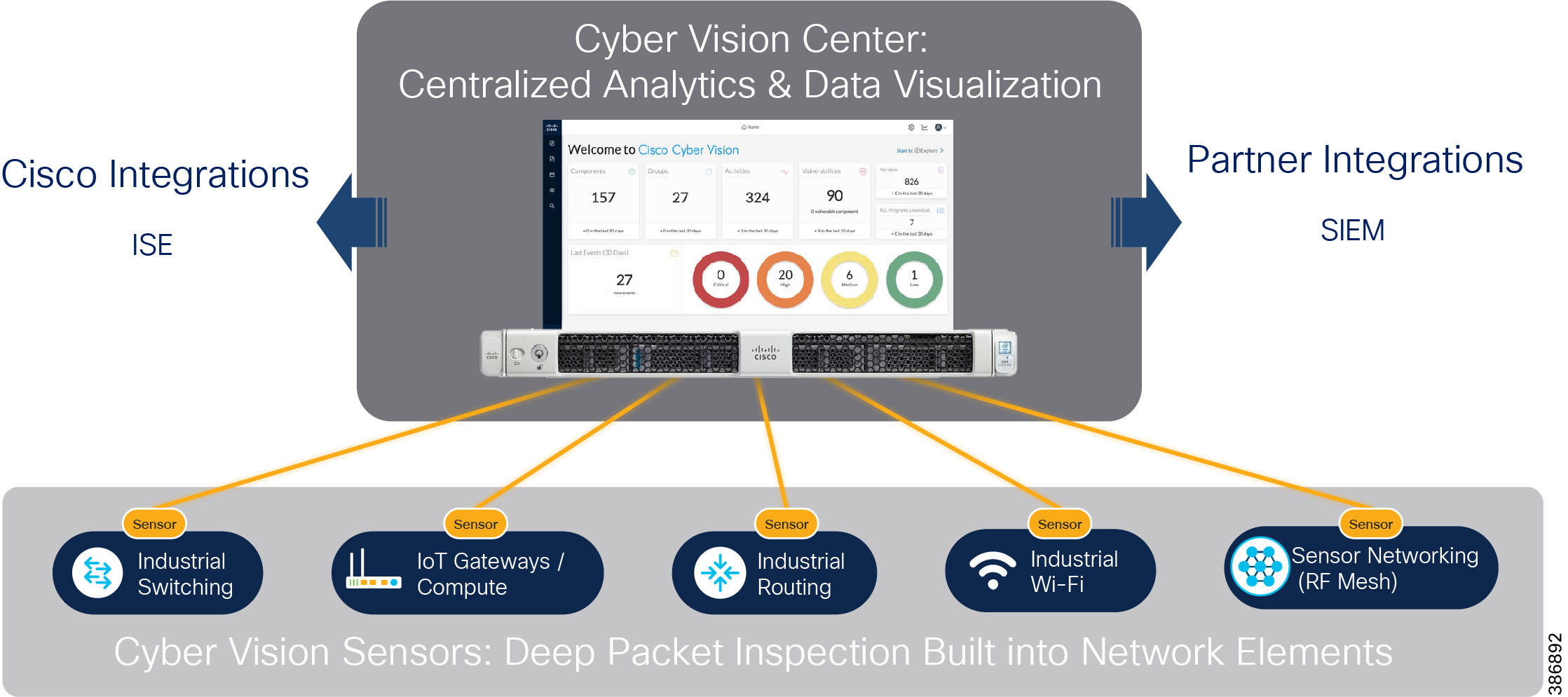
The Cisco Cyber Vision solution is based on a 2-tier architecture made of inline network sensors namely Cisco IE3400 and Cisco IR1101, as well dedicated hardware sensor like Cisco IC3000. These sensors are dedicated to capture network traffic using various SPAN features, decode SCADA protocols as listed in the following table along with other supported IT protocols using the Cisco Deep Packet Inspection engine and send meaningful information to the Cisco Cyber Vision Center for passive monitoring. Support for visibility of legacy protocols is restricted to Cisco IR1101 as Cyber Vision Network sensor.
Table 4 SCADA Protocols supported by Cisco Cyber Vision
| T101 to T104 (Enabled by SCADA Protocol Translation on Cisco IR1101) |
|
Cisco Cyber Vision also enables visibility to the type of devices or components that are part of the network and the flows they generate. For example, the flow could be that of between a SCADA front end processor and its client like control commands, poll, and so on. The device could be a type like PLC or SCADA station or PC as appropriate, and the properties of the device like IP Address, Operating System, Manufacturer, and so on. These details can be derived from the flows or communication generated by the devices in the network. The figure below highlights some of the details that could be deduced with the use of Cisco Cyber Vision. The Cisco Cyber Vision Center, a central platform gathers data from all the Edge Sensors across the network and acts as the monitoring, detection and management platform for the solution.
Figure 25 Gaining visibility using Cisco Cyber Vision Solution
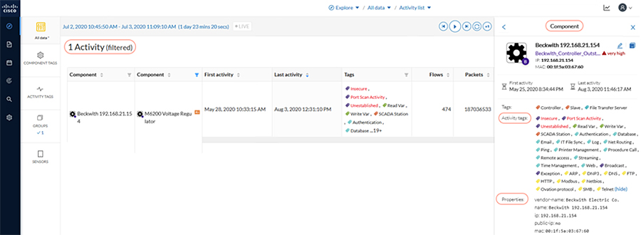
The Cisco Cyber Vision Center can be installed in any of the following ways.
■![]() As a Virtual Machine on VMWare vSphere 6.x or later.
As a Virtual Machine on VMWare vSphere 6.x or later.
■![]() As a Virtual Machine on Microsoft Hyper-V Server 2016 or later.
As a Virtual Machine on Microsoft Hyper-V Server 2016 or later.
This guide proposes installation of the Cisco Cyber Vision Center as a Virtual Machine on VMWare vSphere hosted on Cisco UCS platforms. The user of this guide can choose appropriate installation type based on the requirements.
To operate, the Cisco Cyber Vision Center relies on two separate networks, respectively connected to the following interfaces:
■![]() The Administration network interface, which gives access to the user interface.
The Administration network interface, which gives access to the user interface.
■![]() The Collection network interface, which connects the Cisco Cyber Vision Center to the sensors.
The Collection network interface, which connects the Cisco Cyber Vision Center to the sensors.
Cisco Cyber Vision Center supports various sensors based on the deployment requirement. This guide lists various sensors along with the considerations for different kinds of Electrical Utility network deployments. The different sensors are listed in the following table. The user of this guide can choose appropriate sensor based on the requirements.
Table 5 Cisco Cyber Vision Sensors for Electrical Utility Network
Cisco IC3000 as a Hardware Sensor
The Cisco IC3000 Industrial Compute Gateway is an edge computing platform that supports hosting of different compatible applications. The Cisco Cyber Vision Sensor application can be installed on the IC3000 industrial gateway and deployed as sensor and can be integrated with Cisco Cyber Vision.
The sensor application on IC3000 can be configured to capture traffic from the utility substation LAN network using SPAN. The sensor can be deployed either in offline mode or in online mode. It is recommended to deploy the sensor in online mode as offline mode may require more data storage capability and is not practical for long term deployments.
The IC3000 Sensor supports four ports and all four ports can be connected to different onsite switches in a network as required for further processing and integration with Cyber Vision Center. This setup is described in the following sections. The Cisco IC3000 does not support any networking functionality. It is suitable to be deployed as a Cyber Vision Sensor in places where networking capabilities related to the electrical utility networks are not required on the sensor.
Cisco IR1101 as a Network Sensor
The Cisco Cyber Vision Sensor application can be hosted on a Cisco IR1101 router. The sensor application hosted on IR1101 needs two interfaces, one to connect the sensor to the collection network interface of the Cyber Vision Center and one to monitor the traffic on local IOS interfaces. The Cisco IR1101 IOx uses VirtualPortGroup as means to communicate between IOS and IOx application. A logical mapping of VirtualPortGroup and IOx application is shown in Figure 26.
The Encapsulated Remote Switched Port Analyzer (ERSPAN) can be used to monitor traffic on one or more routed ports or routed Switch Virtual Interfaces (SVI). The ERSPAN source sessions copy traffic from the source-routed ports, or SVIs, and forwards the traffic using routable GRE-encapsulated packets to the ERSPAN destination session, the Cisco Cyber Vision Sensor application in this solution.
Similarly, the application uses a separate interface to send the processed traffic to the collection network interface. To enable reachability of the collection network interface of the Center for the sensor, it is recommended to enable NAT on the VirtualPortGroup and overload using the IR1101 WAN facing interface. The Cisco IR1101 supports serial interfaces that could be used to enable connection of various legacy devices with serial only connectivity options.
Legacy SCADA devices that have support for DNP3, MODBUS, or T101 protocols can be connected to Ethernet-based networks using the Cisco IR1101 as a gateway. The Cisco IR1101 supports SCADA protocol translation capability that can be used to translate T101, T104, or DNP3 Serial to DNP3 IP. The Cisco IR1101 also supports a method to transfer serial data through an IP Network using Raw Socket.
The Cisco Cyber Vision Sensor application on Cisco IR1101 used as a network sensor can enable visibility to some of the serial data. This guide proposes to use the egress IP interface as an ERSPAN source to capture serial data. The egress interface could also be a Flex VPN IPsec tunnel that carries the traffic of interest. Refer to Chapter 4 of this guide for details of IR1101 deployment considerations and various traffic flows.
Figure 26 Cisco IR1101 IOx Application Interface Mapping
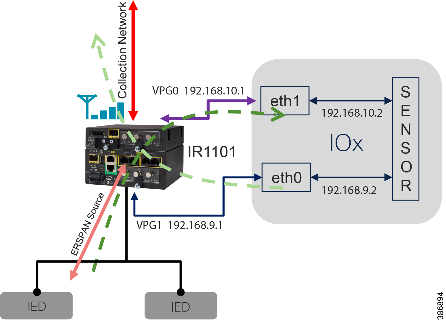
Cisco IE3400 Network Sensor
The Cisco Cyber Vision Sensor application can be hosted on IE3400 Substation Switch. The IOx architecture of the IE3400 provides an internal interface named AppGigabitEthernet1/1 which can be configured in various modes. Configuration can be access or trunk as required and enables connectivity for the hosted application.
Currently, an IOx application interface must have VLAN ID configured even if the AppGigiabitEthernet1/1 interface is configured in access mode. For the hosting of the Cisco Cyber Vision Sensor application, it is recommended to configure the AppGigabitEthernet1/1 as a trunk interface. The sensor application uses two interfaces, one for capturing traffic from the IE3400 switch physical interfaces and one for the Cisco Cyber Vision Center collection network.
The Cisco IE3400 can be used as a Cisco Cyber Vision Network Sensor suitable for substation automation LAN deployments. As explained in Chapter 3, the IE3400 may have multiple VLANs provisioned as part of a substation automation LAN segmentation. Different VLANs can also be provisioned to forward the traffic monitored on physical interfaces or VLANs of IE3400, forward the same traffic to the hosted Sensor application for further processing, or enable connectivity from the sensor to the Cisco Cyber Vision Center collection network interface.
The sensor application expects the source packets to be GRE encapsulated. With the AppGigabitEthernet1/1 interface being a non-routed interface, you can enable ERSPAN on the provisioned AppGigabitEthernet1/1 VLAN for monitoring and forward the packets in the format of ERSPAN to the sensor application. The IE3400 does not support NAT. The collection network-facing interface on the application should be in the same subnet as that of the interface or VLAN on the IE3400 switch that has reachability to the collection network interface of the Cisco Cyber Vision Center. Figure 27 depicts the logical mapping of physical interfaces and the hosted IOx application on the IE3400. Refer to Chapter 3 for details of the IE3400 deployment.
Figure 27 Cisco IE3400 IOx Application Interface Mapping
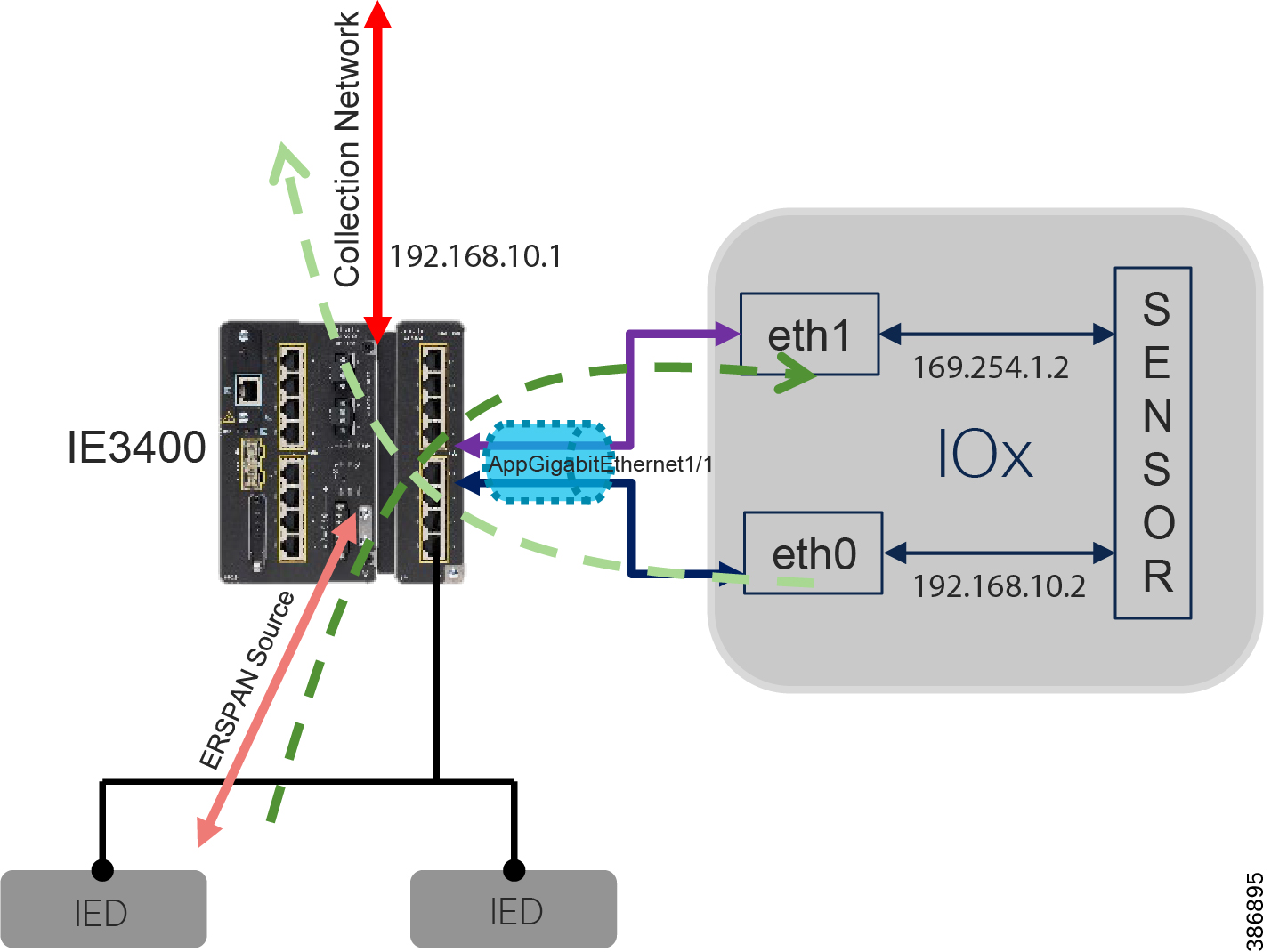
Cisco Cyber Vision Sensor Positioning and Deployment Guidelines
The Cisco Cyber Vision solution success depends on effectively capturing the traffic. Where to capture the traffic in a network is critical. The following figure depicts positioning of various Cisco Cyber Vision Sensors and ISA3000 in few Electrical Utility Network deployments that are being discussed in various sections of this guide.
Figure 28 Grid Security Components and positioning
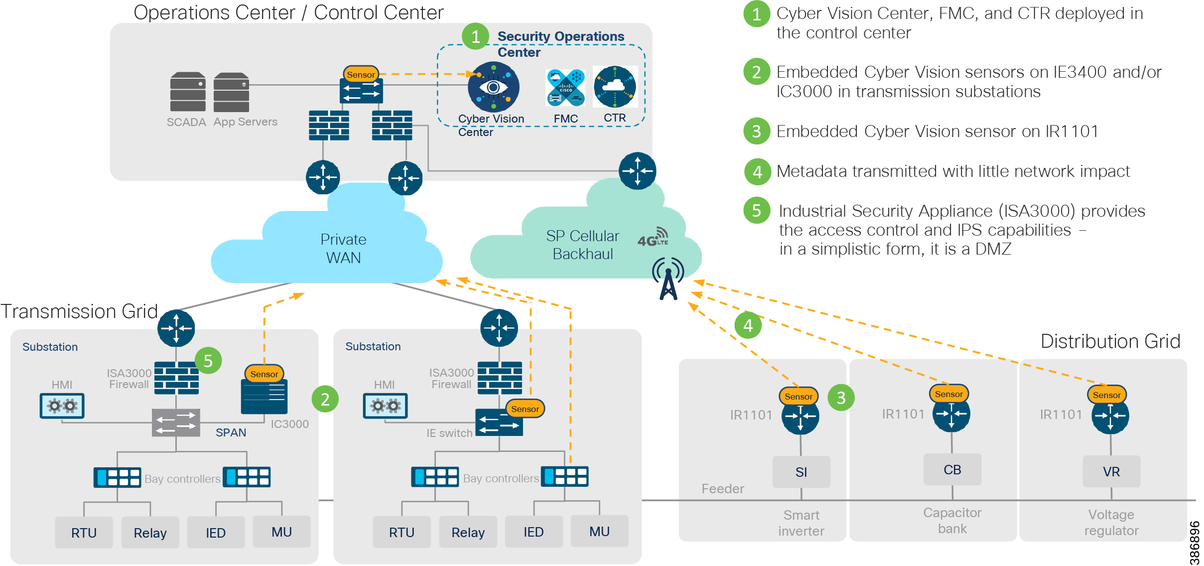
Now consider an example to help understand how different sensors can be positioned for the sample traffic flow as depicted in the following sample Electrical Utility Substation LAN Network. See Figure 29.
Figure 29 Substation LAN Sample Flows
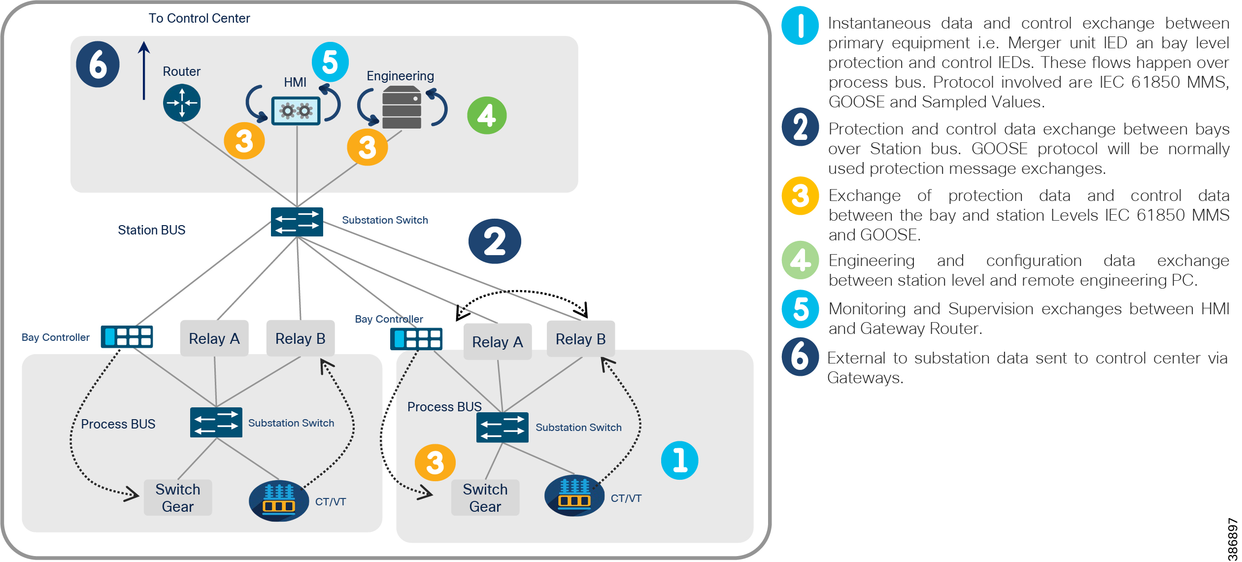
As depicted in Figure 29, there are flows both across and within buses. In such a scenario, it is not feasible to have a single point of capture for all the flows by a single sensor. It is recommended to have a capture point at each of the intersection points or sensors at the intersection points, so that the flows across and within buses can be captured for further processing.
Figure 30 shows how a Cisco IE3400 hosting a Cisco Cyber Vision Sensor application can be positioned in different places across the network for efficient capture of different flows. In this scenario, Cisco IE3400 acts as both a sensor and also a network switch -- a network sensor that does both the functions. It would be suitable to position IE3400 in Green Field network deployments as it does act as both a Substation Switch and Cisco Cyber Vision Sensor.
Figure 30 Substation LAN flows and IE3400 as Cyber Vision Sensor
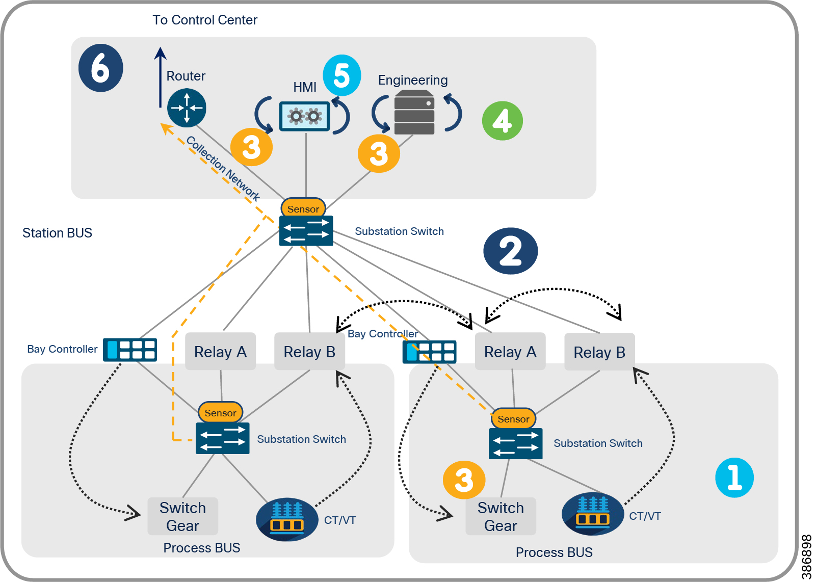
An IC3000 used as a Cisco Cyber Vision Sensor can also be used for the deployment shown in Figure 31. At least three ports of IC3000 are connected to the three substation switches for capturing the different flows within and across the network. In this scenario the Cisco IC3000 does not actively take part in the networking functions of the Substation LAN. It only performs the function of a hardware sensor.
It would also be suitable to position IC3000 if it is in an existing network deployment where in the chances of replacing the substation switch may be less. Laying new cable connections for SPAN traffic, the fact that the traffic will be SPAN-ed to the sensor externally, and the limitation of 4 ports on the sensor for tap points are some of the disadvantages of using Cisco IC3000 as sensor in some deployments. Alternatively, if more than four tap points are required using the IC3000 as sensor, an appropriate switch can be used to aggregate SPAN traffic from various tap points in the network and then connect the IC3000 SPAN interface to the SPAN aggregator switch as shown in Figure 31.
Figure 31 Substation LAN flows and IC3000 as Cyber Vision Sensor
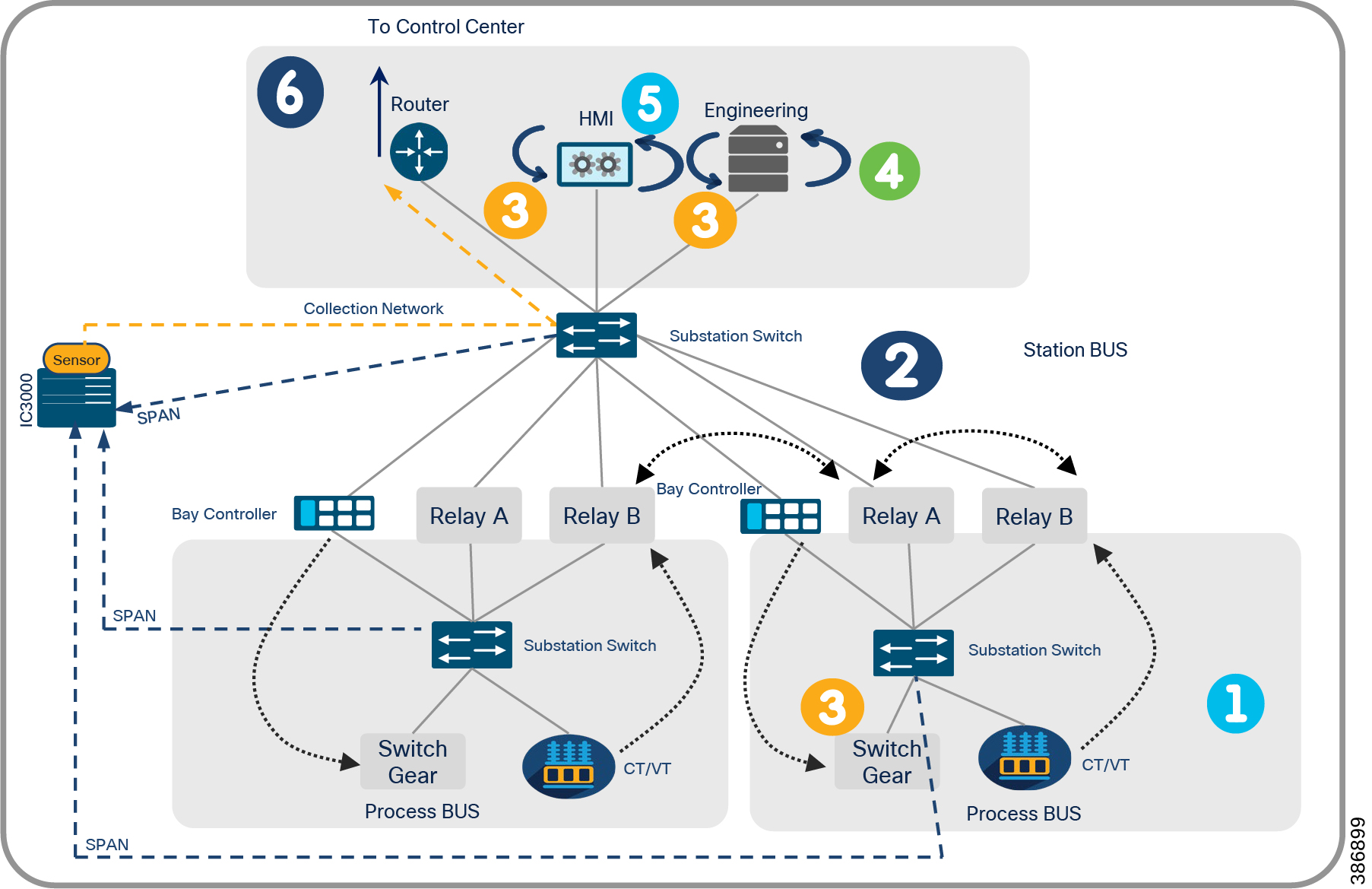
Figure 32 IC3000 Cyber Vision Sensor
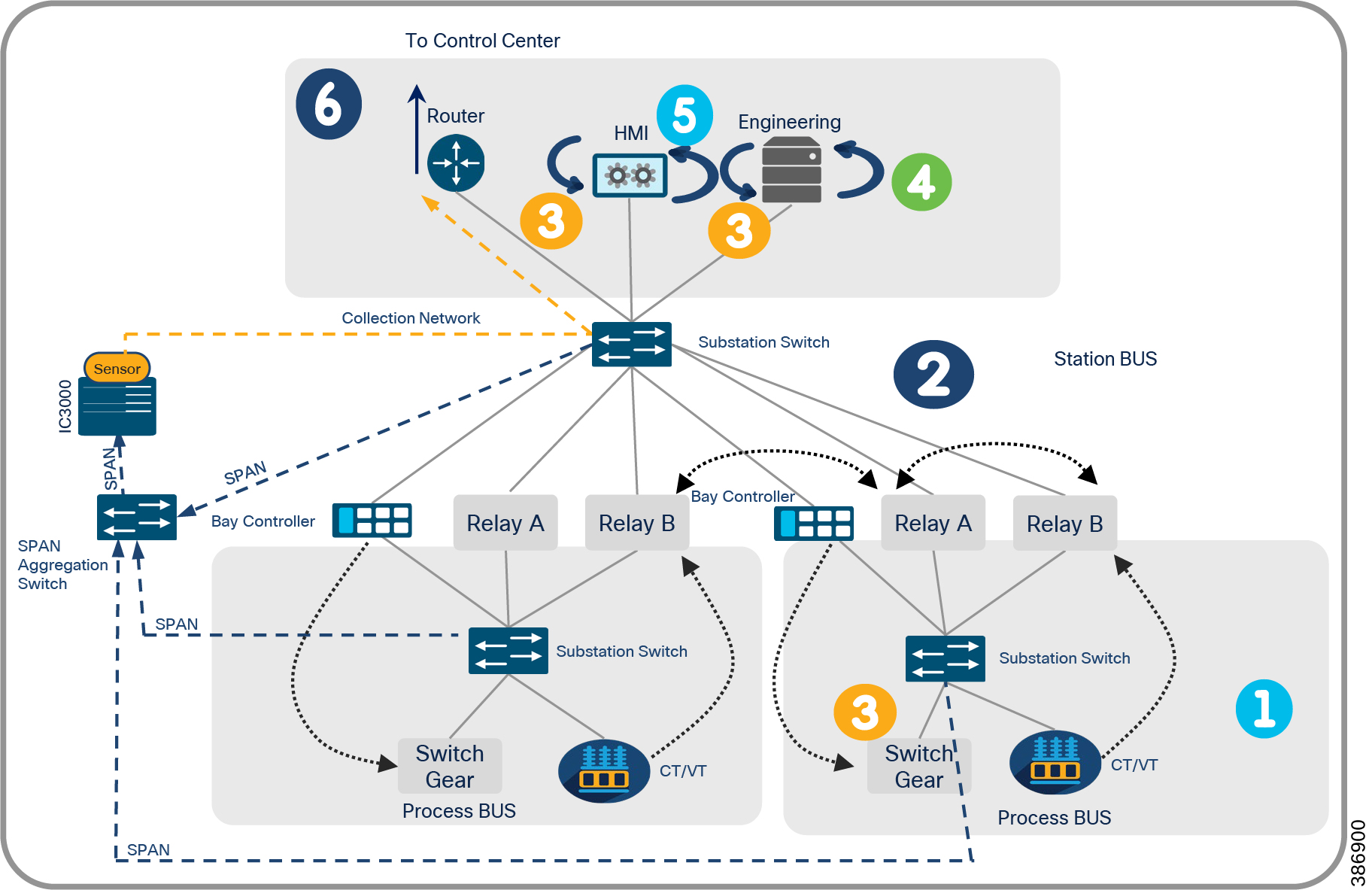
NERC-CIP requirements mandates that the data in Electrical Utility network should be protected. Hence data collected by the network sensors from the industrial network and transported to the CyberVision Center through collection network over WAN, is encrypted. In case of Cisco IR1101 deployed as Network Sensor the encryption of the collection network can be ensured using IPsec via FlexVPN or DMVPN tunnels. In case of Cisco IE3400 the encryption of the collection network can start from the device that can support encryption. The device could be a Cisco substation router like CGR2010 based on the substation network design.
To ensure reliability of the collection network, it can be over carried over Ethernet interfaces with appropriate redundancy mechanisms in case of Cisco IE3400 network sensors deployed as Substation LAN switch or Cellular interfaces in case of IR1101 network sensor deployed as Distribution Automation Gateway with appropriate redundancy mechanisms in place. Refer Chapter 3 and Chapter 4 in this guide for more details.
This design guide proposes to integrate Cisco Cyber Vision Sensor’s Collection network traffic inline along with the existing network traffic of the Electrical Utility Substation LAN instead of creating a separate physical connection to connect the Cisco Cyber Vision Sensor to the Cyber Vision Center’s collection network. It is also recommended to have segmentation of traffic in the Electrical Utility Substation LAN network as mandated by NERC-CIP requirements. Refer to the corresponding section in this guide for more details.
Life Cycle Management of Cyber Vision Sensor
There are various methods available to effectively manage applications on the sensors namely Command Line Interface (CLI), Local Manager Graphical User Interface (LMGUI) and Cyber Vision Center Extension. Each of the different methods have their pros and cons. CLI demands knowledge of various platform commands to successfully deploy, LMGUI and Extension avoids usage of CLIs and tries to simplify the deployment. LMGUI can be used to manage one device at a time whereas Cyber Vision Center Extension helps in upgrading all the sensors managed by it in a single shot. They are not interchangeable.
Cisco Cyber Vision Capabilities
Cisco Cyber Vision Center along with its sensors on successful integration with Electrical Utility network, automatically discovers various details of the production infrastructure: vendor references, firmware and hardware versions, serial numbers, PLC rack slot configuration. It identifies asset relationships, communication patterns, changes to variables, and more. For e.g., in case of DNP3 protocol commands like READ, WRITE, etc. from the SCADA Controller to the SCADA Client and UNSOLICITED REPORTING from the SCADA Client to the SCADA Controller will be sensed by the Cisco Cyber Vision Sensor and reported by Cisco Cyber Vision Center. On the similar lines, with appropriate platform and feature support DNP3 Serial to DNP3 TCP/IP translated packets also can be sensed by Cisco Cyber Vision Sensor. This wealth of information is shown in various types of maps, tables, and reports that maintain a complete inventory of industrial assets, their relationships, their vulnerabilities, and the programs they run.
Cisco Cyber Vision Center can be integrated with Cisco ISE using pxGrid to exchange some of its discoveries like Asset details. Cisco ISE can be configured to use these details to define required access control policies and ensure that the devices seeking access to the network are authenticated and authorized as NERC-CIP requirement mandates. Cisco Rapid Threat Containment simplifies and automates network mitigation and investigation actions in response to security events. It integrates Cisco ISE and Cisco security technology partner solutions in a broad variety of technology areas. With Threat-Centric Network Access Control (TC-NAC), it can change user access based on CVSS vulnerability and STIX threat scores. With the Cisco pxGrid Adaptive Network Control (ANC), it gives one the ability to reset the network access status of an endpoint to quarantine, unquarantine, bounce, or shut down a port.
Threat Detection and Mitigation
Cisco Cyber Vision provides a monitoring tool called the Monitor mode to detect changes inside industrial networks. Because a network architecture (IED, switch, SCADA) is constant and its behaviors tend to be stable over time, an established and configured network is predictable. However, some behaviors are unpredictable and can even compromise a network's operation and security. The Monitor mode aims to show the evolution of a network's behaviors, predicted or not, based on presets. Changes, either normal or abnormal, are noted as differences in the Monitor mode when a behavior happens. Using the Monitor mode one can detect the flows that could possibly be an Anomaly. Such events are reported by Cyber Vision and can also be forwarded in the form of Syslog to SIEMs for further processing. The following figure logically explains how the baseline and monitor functions in Cisco Cyber Vision works to detect anomalies in the network.
Figure 33 Baseline and Anomaly Detection by Cyber Vision
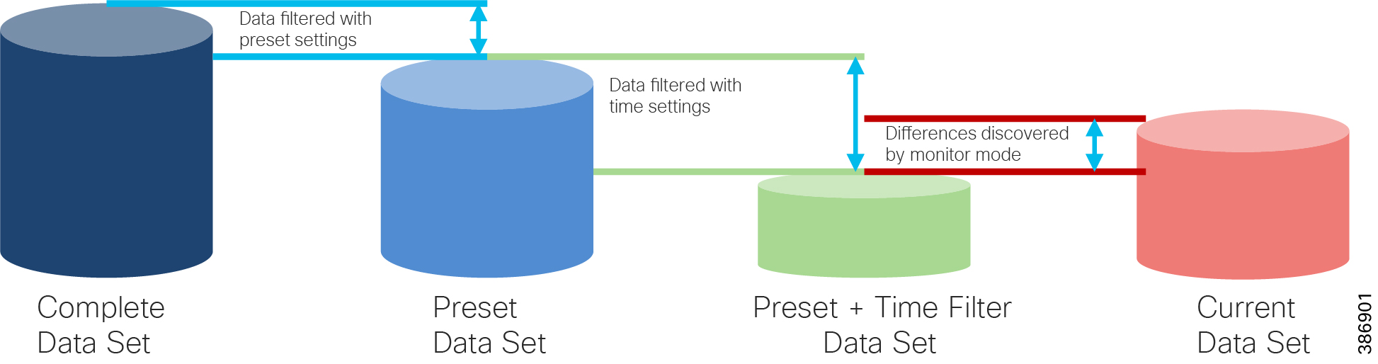
The Cisco ISA 3000 Series is purpose built for industrial Ethernet applications where hardened products are required. With Cisco Firepower Threat Defense supported on ISA3000, deployment of the Cisco ISA 3000 industrial firewall can fulfill security requirements associated with a variety of industrial standards, regulations, and guidelines such as NERC-CIP, ISA 99, ISA 62443, CFATS, ANSI/AWWA G430, and others.
This guide proposes Cisco ISA3000 with FTD as a firewall appliance for the Electrical Utility Substation Automation LAN networks. This section lists some of the considerations for Visibility, Anomaly Detection and Mitigation using ISA3000. Configure appropriate license and firewall policies. These are Access Control policy, Identity policy, Intrusion policy, Malware Policy, and others on the ISA3000 FTD device. The policies aid the user to gain insight into the Electrical Utility Substation LAN network IT traffic and detect vulnerabilities, malware that may exist in such flows.
Use the Cisco ISA3000 preprocessor for SCADA protocols like MODBUS, DNP3. The preprocessor helps in detecting protocol anomalies like bad CRC, detects reserved functions of the protocols being used, invalid length, and so on. As an anomaly or vulnerability or malware is detected, the FTD can be configured to take appropriate action like dropping the flows or mitigate the threat with ISE integrated. It is recommended to use Cisco Firepower Management Center to effectively manage ISA3000.
The following figure illustrates a sample threat mitigation scenario in a Substation LAN environment using Cisco Cyber Vision, ISA3000 and FTD. Cisco Cyber Vision detects an Anomaly, notifies ISA3000 FTD to take action for the notified anomaly.
Figure 34 Sample Threat Mitigation using Cyber Vision
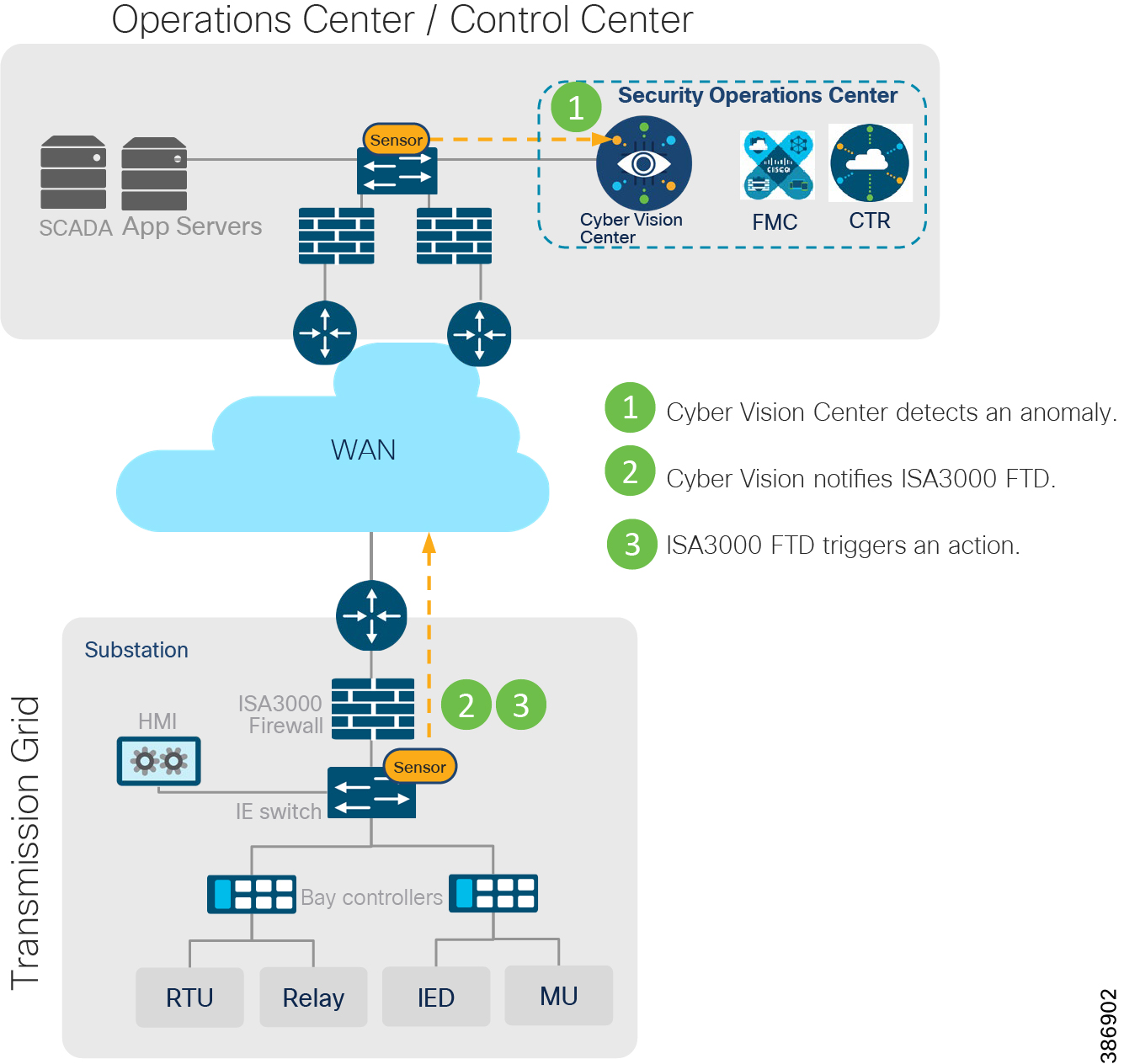
The following illustration summarizes the various components and the functions the components carry in the solution that this guide proposes for the security of an Electrical Utility network.
Figure 35 Electrical Utility Network Components and Functions
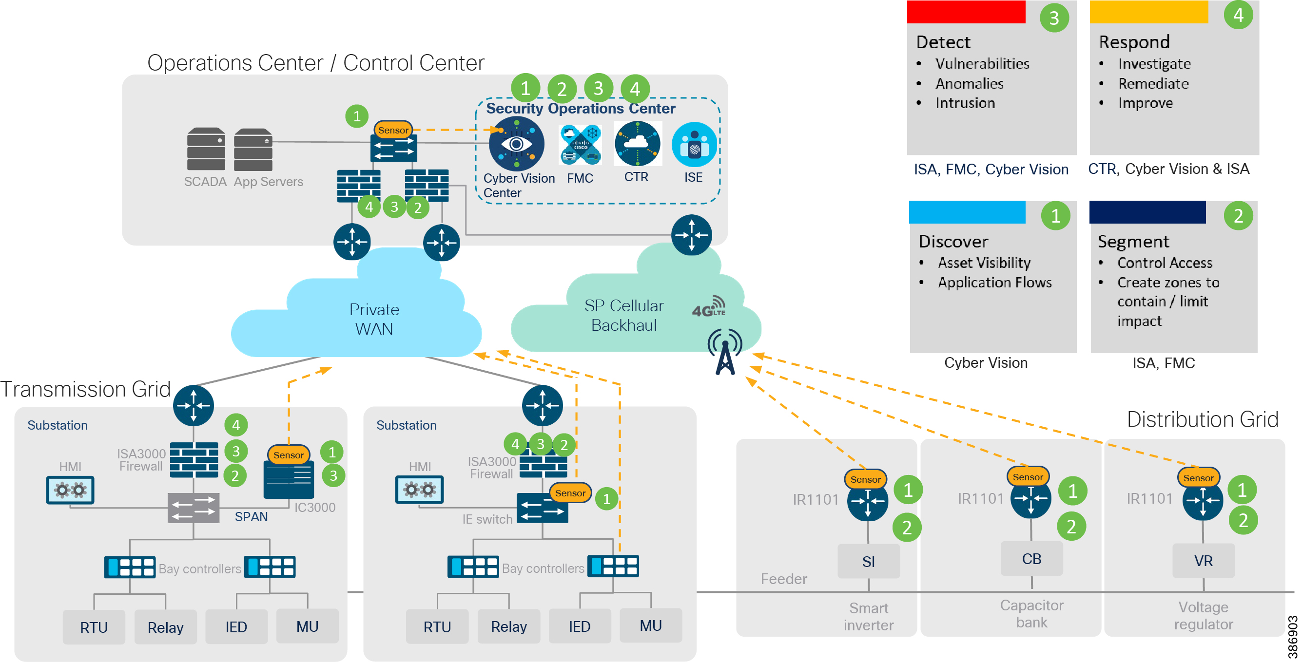
Summary
This design guide has described the integration of multiple security platforms to establish a comprehensive defense-in-depth approach to grid security. The design considerations and the detailed validation and configuration information will be in the accompanying implementation guide.
These integrated systems improve operational capabilities and protection for the systems; the integration and centralized management significantly reduce operational costs, time, and threat exposure. This is the benefit of one system versus integrating numerous questionable compatibility points from multiple vendors.
This design guide leverages previous validation efforts and now shows the integration of these as a holistic architecture adding the capabilities of Cisco Cyber Vision.
Cisco Cyber Vision is an asset inventory, network monitoring, and threat intelligence platform specifically designed to secure Industrial Control Systems (ICS). It is embedded into the Cisco range of industrial network equipment to gather real-time information on industrial assets and processes to give visibility into the production infrastructure and enrich security events with industrial context. Cisco Cyber Vision lets IT and OT teams share a common understanding of their industrial networks and operational events. They can work together on network segmentation, threat detection, and remediation to ensure continuity, resilience, and safety of their industrial operations. Fully integrated with the Cisco security portfolio, Cisco Cyber Vision extends the SOC to the OT domain, so that organizations can build and apply security policies to their industrial networks based on operational insights.
Appendix A: Glossary
The following table lists the acronyms and initialisms that may be used in this document.
|
|
|
Appendix B: Compliance and Solution Mapping


Appendix C: Product Mapping and Alignment to NERC-CIP
Appendix D: Modbus and DNP3 Function codes
Table 6 Table Modbus function code
The following DNP3 functions and internal indicators are available to perform IPS functionality.
Table 8 DNP3 Internal Indicators flags present in a DNP3 Application
Appendix E: Reference and related documentation
Cisco Substation Automation CVD
https://www.cisco.com/c/en/us/td/docs/solutions/Verticals/Utilities/SA/2-3-2/CU-2-3-2-DIG.html
Cisco Distribution Automation Design Guide
https://www.cisco.com/c/en/us/td/docs/solutions/Verticals/Distributed-Automation/Secondary-Substation/DG/DA-SS-DG.html
https://www.cisco.com/c/en/us/products/security/industrial-security-appliance-isa/index.html
https://www.cisco.com/c/en/us/products/security/cyber-vision/index.html
https://www.cisco.com/c/en/us/products/security/firepower-management-center/index.html
https://www.cisco.com/c/en/us/td/docs/security/firepower/quick_start/fp4100/firepower-4100-gsg/ftd_fdm_deploy.html
https://www.cisco.com/c/en/us/products/routers/1100-series-industrial-integrated-services-routers/index.html
https://www.cisco.com/c/en/us/products/switches/catalyst-ie3400-rugged-series/index.html
https://www.cisco.com/c/en/us/products/switches/industrial-ethernet-4000-series-switches/index.html
https://www.cisco.com/c/en/us/products/collateral/switches/industrial-ethernet-5000-series-switches/datasheet-c78-734967.html
https://www.cisco.com/c/en_in/products/security/identity-services-engine/index.html
https://www.cisco.com/c/en/us/products/collateral/routers/3000-series-industrial-compute-gateways/datasheet-c78-741204.html
 Feedback