- Executive Summary
- Navigator
- Audience
- Document Objective and Scope
- Use Cases/Services/Deployment Models
- Solution Overview
- SEL FLISR Use case Validation Call Flow Sequence
- Cisco SEL FLISR Use case – Urban Topology
- Urban FLISR Topology - SEL device to Cisco device mapping
- FLISR Fault scenario - Fault with Lock Out
- FLISR Fault scenario – Open Phase
- FLISR Fault scenario – Loss of Source
- Cisco SEL FLISR Use case – Rural Topology
- SEL FLISR Rural Topology - FLISR Fault scenario - Fault with LockOut
- SEL FLISR Rural Topology - FLISR Fault scenario – Open Phase
- SEL FLISR Rural Topology - FLISR Fault scenario – Loss of Source:
Distribution Automation - Feeder Automation Design Guide
The Cisco Distribution Automation - Feeder Automation Design Guide provides a comprehensive explanation of the entire end-to-end Cisco Smart Grid Field Area Network (FAN) solution design, which was developed for the Utility Industry in the Americas region and leverages the license free spectrum: ISM band 902 - 928 MHz for last mile connectivity of the Distribution Network Grid devices. The document describes the two most common Distribution Automation use cases for monitoring and control of Distribution electrical lines equipment: Volt/VAR and Fault Location, Isolation, and Service Restoration (FLISR). It also includes information about the system's architecture, solution components, product choices, design models, and design considerations. This design targets implementations that will use the customer's Substation Private WAN as backhaul for the Resilient Mesh Network to transport data from grid devices in the field to the Control and Operation Centers. The document concludes with a high-level overview of a Feeder Automation Design based on Public Cellular Service that leverages Cisco's Cellular Industrial Routers (IR) Series products.
Executive Summary
Several key business drivers underlie the optimization of the distribution grid enabled by this solution. A pervasive, highly available, and well designed communications network will help enable increased reliability and availability while also reducing OpEx.
Cisco Systems is addressing the networking needs of the utility industry. Specifically, in this Distribution Automation - Feeder Automation Design Guide, the communications solutions that address the utility distribution grid with use cases such as SCADA transport, FLISR, and line voltage-monitoring enabling applications such as Volt/VAR Control are being highlighted. Field devices like transformers can offer predictive maintenance opportunities that will help eliminate customer outages and expensive unscheduled repairs and truck rolls.
The Cisco Distribution Automation validated solution, which is part of the Cisco portfolio of industry-leading, validated, and secure networking solutions for substation automation, Utility WAN, and Field Area Network Advanced Meter Infrastructure (FAN AMI), provides the following unique capabilities for distributed control and protection operations:
■![]() Cisco Resilient Mesh and cellular networking with FlexVPN technologies that are cost-effectively built to scale for the large number of Distribution Automation devices being enabled in the distribution grid
Cisco Resilient Mesh and cellular networking with FlexVPN technologies that are cost-effectively built to scale for the large number of Distribution Automation devices being enabled in the distribution grid
■![]() An IT-preferred security architecture, including hardware and software certification management, firewall, and malware protection with robust encryption to help ensure secure network communications and edge applications
An IT-preferred security architecture, including hardware and software certification management, firewall, and malware protection with robust encryption to help ensure secure network communications and edge applications
■![]() Enhanced management and serviceability by Cisco Field Network Director (FND) with Zero Touch Deployment (ZTD) and plug-and-play (PnP) functionality to help enable deployment and enhance operations
Enhanced management and serviceability by Cisco Field Network Director (FND) with Zero Touch Deployment (ZTD) and plug-and-play (PnP) functionality to help enable deployment and enhance operations
■![]() High availability that is designed in the headend and Wide Area Network (WAN), with redundant control center support
High availability that is designed in the headend and Wide Area Network (WAN), with redundant control center support
■![]() Edge application capabilities within FND lifecycle-managed Cisco equipment that include deployment, monitoring, upgrading, and troubleshooting
Edge application capabilities within FND lifecycle-managed Cisco equipment that include deployment, monitoring, upgrading, and troubleshooting
■![]() End-to-end testing and validation, which are completed and documented with various Distribution Automation device vendors and use cases
End-to-end testing and validation, which are completed and documented with various Distribution Automation device vendors and use cases
The recent enhancements to Cisco Resilient Mesh have increased by nearly tenfold the available bandwidth on the 900mhz field area network over the first generation, thus also reducing the latency between hops, helping enable peer-to-peer communication, and equipping the network with enhanced security features. Cisco has transformed a previously low performance wireless mesh network that was designed for smart metering into a network that is suitable for Distribution Automation use cases.
Cellular can be applied to areas or use cases where extremely high performance is needed. Since they are managed under a single highly usable Field Network Director (FND) system, the customer will receive a consistently intuitive management experience.
As a foundational element to any Cisco network, this DA architecture leverages enhanced security from the control center to the edge of the distribution network. The result is a reliable, scalable, and highly available DA network via wired and wireless, and a cellular WAN that supports large-scale DA deployments and secures communications to redundant control centers.
Deployment, ongoing operation, and management is simplified via standards-based protocols and ZTD tools for proven large scale DA network provisioning. This is all addressed in detail as part of this design guide.
This document covers this DA communications solution, which is based on industry-leading innovations in Cisco Resilient Mesh and cellular networking technologies that are built into the Cisco CGR 1240 and CGR 1120 Connected Grid Routers; the Cisco IR510 and IR530 Wi-Sun Mesh Industrial Routers product family; the IR807, IR809, and IR1101 Industrial Router cellular gateways; and the Cisco FND management system.
Navigator
The table describes the chapters in this document:
|
|
|
Review of the Utility Industry Distribution Use Cases: Volt/VAR and FLISR. It is intended for readers who are unfamiliar with the industry DA applications. |
|
Introduction to Cisco solution's product portfolio, product characteristics, and usage guidance for product selection based on utility footprint with reference links to documentation across the three main tiers: NAM, WAN, and Energy Operations Center or DC. |
|
Describes at a high level the different industry DA architectures (centralized versus distributed) and the three Cisco FAN design options available to support these DA architectures. |
|
Design Considerations for DA Feeder Automation Deployments Based on 900MHz ISM Band Solution |
Explains in detail the Cisco FAN Distribution Automation design based on 900Mhz ISM band Spectrum. It also contains the design specifications and functional description of aspects such as RF communication, network infrastructure, routing, security, and QoS across the FAN tiers. |
DA Feeder Automation using Cellular Service (3G/4G) Solution |
Overview of the Cisco FAN DA design based on Public Cellular Service solution. |
Audience
The intended audience for this guide is comprised of, but is not limited to, system architects, network/compute/systems engineers, field consultants, Cisco Customer Experience (CX) specialists, partners, and customers.
The solution encompasses multiple technology domains from infrastructure to switching and routing to security and network management. Readers should be familiar with the following transport technologies: Radio: IEEE802.15.4 based on 900MHz ISM band, IEEE 802.11 Wi-Fi and Cellular 3G/4G, IEEE 802.3 Ethernet, and overlay Virtual Private Networks: FlexVPN. The solution uses the following industry standard protocols: IPv4 and IPv6, 6LoWPAN, RPL, BGP, NAT (MAP-T), IKEv2, 802.1x, 802.11i, SNMP, and CoAP, including others.
Document Objective and Scope
This design guide provides a comprehensive explanation of the Cisco FAN system design based on standard unlicensed ISM 900MHz radio band frequency for Utilities Distribution Automation applications. It includes information about the system's architecture, possible deployment models, and guidelines for implementation and configuration. The guide also recommends best practices and potential issues when deploying the reference architecture.
Use Cases/Services/Deployment Models
This guide addresses the following technology use cases:
■![]() DA grid devices connectivity using unlicensed frequency radio: ISM 902-928MHz band available in certain countries in the Americas market, standard IEEE 802.15.4g/e based on Option 2 - OFDM modulation with higher physical data rates of up to 1.2Mbps.
DA grid devices connectivity using unlicensed frequency radio: ISM 902-928MHz band available in certain countries in the Americas market, standard IEEE 802.15.4g/e based on Option 2 - OFDM modulation with higher physical data rates of up to 1.2Mbps.
■![]() Radio Optimization features: Adaptive Modulation, Adaptive Data Rates, and High Availability for mesh coordinator.
Radio Optimization features: Adaptive Modulation, Adaptive Data Rates, and High Availability for mesh coordinator.
■![]() Edge Software Optimization features: for customer application edge deployment with dedicated resources.
Edge Software Optimization features: for customer application edge deployment with dedicated resources.
■![]() Advanced mesh IPv6 routing with peer-to-peer communication.
Advanced mesh IPv6 routing with peer-to-peer communication.
■![]() New products release CGR 1000 Wireless Module (WPAN), IR510 DA Gateway, and IR530 DA Range Extender.
New products release CGR 1000 Wireless Module (WPAN), IR510 DA Gateway, and IR530 DA Range Extender.
Distribution Automation Architecture for Utilities
This chapter includes the following major topic:
■![]() Distribution Automation Use Cases
Distribution Automation Use Cases
Cisco Systems has taken a holistic approach to Distribution Automation, and, in this release, the focus will be the Utility Distribution system. The goal of Distribution Automation in the Utility grid is real-time adjustment to changing loads, distributed generation, and failure conditions within the Distribution grid, usually without operator intervention. The IT infrastructure includes real-time data acquisition and communication with utility databases and other automated systems. Accurate modeling of distribution operations supports optimal decision making at the control center and in the field. This heavily depends on a highly reliable and high performing communications infrastructure. This document address these communications requirements as an architecture and addresses the key use cases below.
Distribution Automation technologies are commercially available for wide scale utility deployments. The key for the utility is to identify and unlock the value that these solutions provide. Applications that may have the greatest potential are those that directly affect operations and efficiency such as management of peak load via demand response, predictive technologies for advanced maintenance or equipment replacement and secure communications for equipment, and system restoration technologies.
Automated control of devices in distribution systems is the closed-loop control of switching devices, voltage controllers, and capacitors based on recommendations of the distribution optimization algorithms. These closed loop systems often have rigorous communications systems requirements that vary from manufacturer to manufacturer and by application. The communications system must meet the most rigorous standards and do so at scale. Volt/VAR control is one of the key applications to optimize the distribution grid for the utility.
A utilities fault may occur when a short circuit between two-phase lines occurs or for other reasons. The fault in any one of the lines can affect a large number of customers. Before the fault on the line can be corrected, it has to be identified and isolated from the large utility network. This identification and isolation is done by placing reclosers in the network. The reclosers are in turn connected to the recloser controller. The recloser controller is a connected gateway, which establishes a connection to the control center.
When a fault is identified, the reclosers perform the trip operation and the fault is isolated from the larger network. This trip operation can be automated or can be sent from the control center. Once the fault is corrected, the close operation on the circuit, which is done from the control center, can be executed. This is commonly referred to as FLISR, and is also one of the key use cases for a utility in a grid optimization effort.
This Distribution Automation architecture address the utility requirements for Volt/VAR and FLISR via a robust communications infrastructure that addresses the two predominant distribution automation schemes:
In Europe, portions of South America, and Asia, the distribution scheme is based on a more centralized transformer design and is commonly referred to as the Secondary Substation.
In North America, portions of South America, and along the Pacific Rim, the distribution scheme is based on a decentralized transformer model and this scheme will be referred to throughout this document as a Feeder Network.
The architecture in Figure 1 leverages the latest technologies and recent enhancements to best address use cases and these topologies with a variety of cell-based gateways for the Secondary Substation as well as a combination of 900 Mhz mesh and cell gateways at the edge. The architecture addresses the requirements for these edge services and communications, including the edge as NAN, the backhaul as WAN, and the Operations and Control Centers commonly referred to as the Headend.
Figure 1 Reference Architecture for Distribution Automation
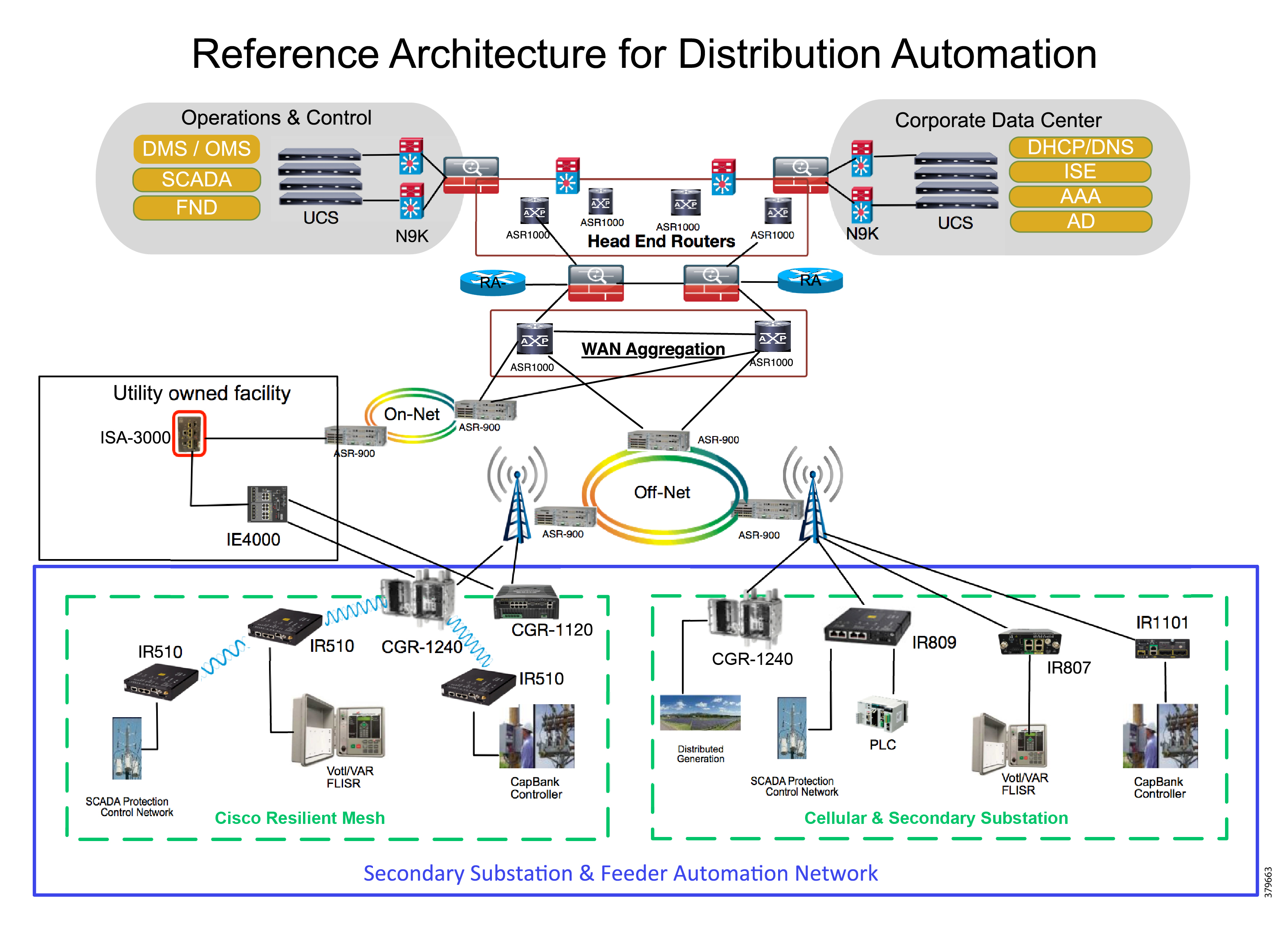
The Headend provides aggregation and security for and between the distribution automation applications typically at the Utility control center. This architecture leverages a secure WAN aggregation for scalability since feeder sections may scale to hundreds or more devices with the DA network scaling to thousands of feeder segments and Secondary Substation networks with over 100,000 nodes.
As part of this architecture, the WAN segment is referred to in two modes: On-Net and Off-Net:
■![]() On-Net is a high speed communications network owned and operated by the utility; examples include SDH/SONET, Carrier Ethernet, or MPLS as the most common.
On-Net is a high speed communications network owned and operated by the utility; examples include SDH/SONET, Carrier Ethernet, or MPLS as the most common.
■![]() On the other hand, the Off-Net network is a service provider-leveraged network that can be based on the same technologies but as a shared service that often includes pre-negotiated service level agreements.
On the other hand, the Off-Net network is a service provider-leveraged network that can be based on the same technologies but as a shared service that often includes pre-negotiated service level agreements.
The WAN segment for DA networks is often a cellular backhaul connection because building out a private network in numerous and remote locations, especially in the Secondary Substation model, is frequently cost prohibitive. The NAN Mesh offers opportunities to leverage the On-Net network as backhaul when the radio network gateway can be co-located at a utility-owned facility such as a substation or depot.
The edge or the NAN is built on a small form factor gateway or NAN router connected to the edge device such as a Capacitor Bank Controller (CBC) or voltage line monitor based on application or service. The connection to the edge device is often serial, but is rapidly moving to Ethernet. The NAN router can be configured to deliver edge services such as adaptation for serial connections via raw socket encapsulation or translation from serial protocols like IEC-101 to the packet-based IEC-104 protocol. The NAN router also provides security services such as 802.1x port-based authentication, encryption, and routing with possible alternate backhaul options, thus providing a secure connection for the edge device to the control center. The backhaul in the case of Secondary Substations is most often cellular with some satellite or DSL options.
Cisco Resilient Mesh is the latest version of the 900 Mhz Connected Grid Mesh radio with significant performance improvements now applicable for many Distribution Automation applications and use cases. However, it is recognized that Resilient Mesh may not be applicable for all use cases. The Distribution Feeder network will likely be a combination of mesh where the 900 Mhz radio network is feasible and hop count and latency meet application requirements with cellular to augment based on hop count, application performance, or latency requirements.
Distribution Automation Use Cases
Distribution Automation (DA) refers to the monitoring and control of devices located on the distribution feeders, such as line reclosers, load break switches, sectionalizers, capacitor banks and line regulators, and devices located in the distribution substation. DA is an overlay network deployed in parallel to the distribution feeder. It enables two-way communication between controllers used in the distribution feeder and the intelligence application that resides in the Utility control center or Secondary Substation for improving grid reliability, availability, and control. Figure 2 depicts a radial distribution feeder:
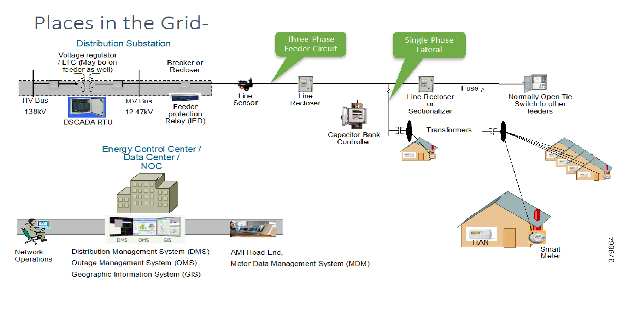
In Figure 2, the distribution feeder can be observed coming out of the Secondary Substation; various distribution automation controllers (IEDs) in the feeder, such as the recloser controller, voltage regular controller, and capacitor bank controller, are positioned along the distribution feeder. Key functions and operations of Distribution Automation include protecting the distribution system, managing the fault, measuring the energy usage, managing the assets, and controlling and managing system performance. European feeders are largely three-phase and most European countries have a standard secondary voltage of 220, 230, or 240 V.
Use Cases
The following use cases of Distribution Automation will be discussed in this design guide:
■![]() Fault Location Isolation and Service Restoration (FLISR)
Fault Location Isolation and Service Restoration (FLISR)
The radial feeder distribution system design is considered for Volt/VAR regulation use cases and the parallel feeder distribution system is considered for FLISR use cases. Cisco DA Gateways are very well suited for other feeder deployments such as mesh and loop distributed feeder designs.
Volt/VAR Control Use Cases and Benefits
This use case address automating dynamic and efficient delivery of power. Utilities look at achieving large saving by enhancing the efficiency of their power distribution infrastructure-in other words, improving the effectiveness of the flow of electricity. In order to evaluate the process, it is important to review the differences between what is called real power and reactive power.
■![]() Real power is used to run all lights, devices and production lines. It is the power that "does the work."
Real power is used to run all lights, devices and production lines. It is the power that "does the work."
■![]() Reactive power does not contribute anything to doing work, but it does cause conductors to heat up and it takes up a certain amount of "space" in the wires.
Reactive power does not contribute anything to doing work, but it does cause conductors to heat up and it takes up a certain amount of "space" in the wires.
The more reactive power flowing on a line, the less "room" there is for real power, and the less efficient is the distribution system.
Today, in order to eliminate or at least minimize reactive power flows, utilities have deployed on their local distribution systems devices, such as capacitor banks or special transformers that are typically located at substations or on the feeder. These devices work to keep reactive power flows down, making the full capacity of the conductor available for the real power. This process is known as Volt/VAR regulation or control:
■![]() Power Factor Regulation/VAR Compensation—Improves efficiency of energy supply by ensuring voltage and current are in phase when supplied to the customer.
Power Factor Regulation/VAR Compensation—Improves efficiency of energy supply by ensuring voltage and current are in phase when supplied to the customer.
■![]() Conservation Voltage Regulation—At times of peak load, ensure the minimum required voltage level is supplied to the customer.
Conservation Voltage Regulation—At times of peak load, ensure the minimum required voltage level is supplied to the customer.
■![]() Volt/VAR Control—Power factor regulation + Conservation voltage regulation.
Volt/VAR Control—Power factor regulation + Conservation voltage regulation.
Volt/VAR Actors
Figure 3 depicts various actors used in the Volt/VAR use case. The actors used in the Volt/VAR use case are Load Tap Changers, Voltage Regulators, and Capacitor Bank Controllers (CBCs).
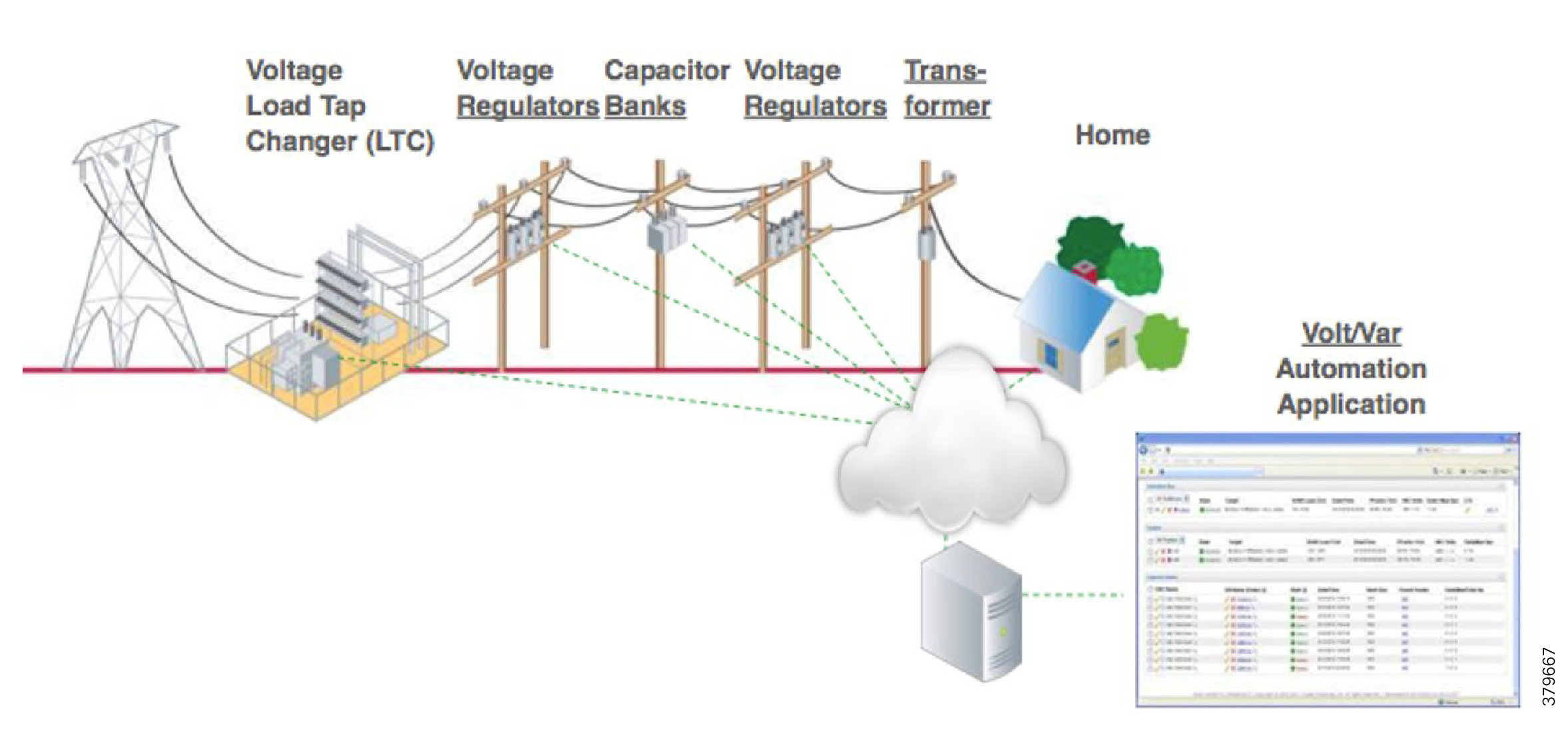
Voltage Regulator and Load Tap Controllers
Voltage regulation functions are performed using the Voltage Regulator/Load Tap Controller actors. Voltage can be raised or lowered based on load conditions. Voltage Regulators are types of transformers that make small adjustments to voltage levels in response to changes in load. They are installed in substations (where they are called load tap changers) and along distribution feeders to regulate downstream voltage. Voltage Regulators have multiple "raise" and "lower" positions and can automatically adjust according to feeder configurations, loads, and device settings.
Capacitor Bank Controllers
CBCs are used to supply reactive power. Utilities use capacitors to compensate for reactive power requirements caused by inductive loads from customer equipment, transformers, or overhead lines. Compensating for reactive power reduces the total amount of power that needs to be provided by power plants, resulting in a flatter voltage profile along the feeder and less energy wasted from electrical losses in the feeder. A distribution capacitor bank consists of a group of capacitors connected together. Capacitor banks are mounted on substation structures, distribution poles, or are "pad-mounted" in enclosures.
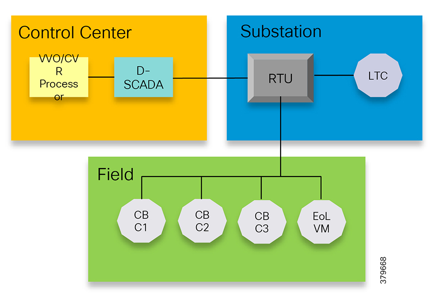
Volt/VAR Application Communication Flow
In Figure 4, Volt/VAR and Supervisory Control and Data Acquisition (SCADA) applications are hosted in the DSO control center and RTU and load tap controllers are located in the Secondary Substation. The remote terminal unit (RTU) acts as an outstation device that proxies the poll and/or control command to various field devices like the CBC and end-of-line voltage monitor. This guide covers the use case scenario where the Volt/VAR application flow between the Intelligent Electronic Device (IED) and SCADA happens via RTU and the distribution feeder type considered is radial. A direct application flow from field devices to the control center for the Volt/VAR use case will be covered in future guides.
Figure 4 Volt/VAR Block Diagram
The detailed application flow between different actors for power factor regulation is depicted in Figure 5:
Figure 5 Power Factor Regulation Flows
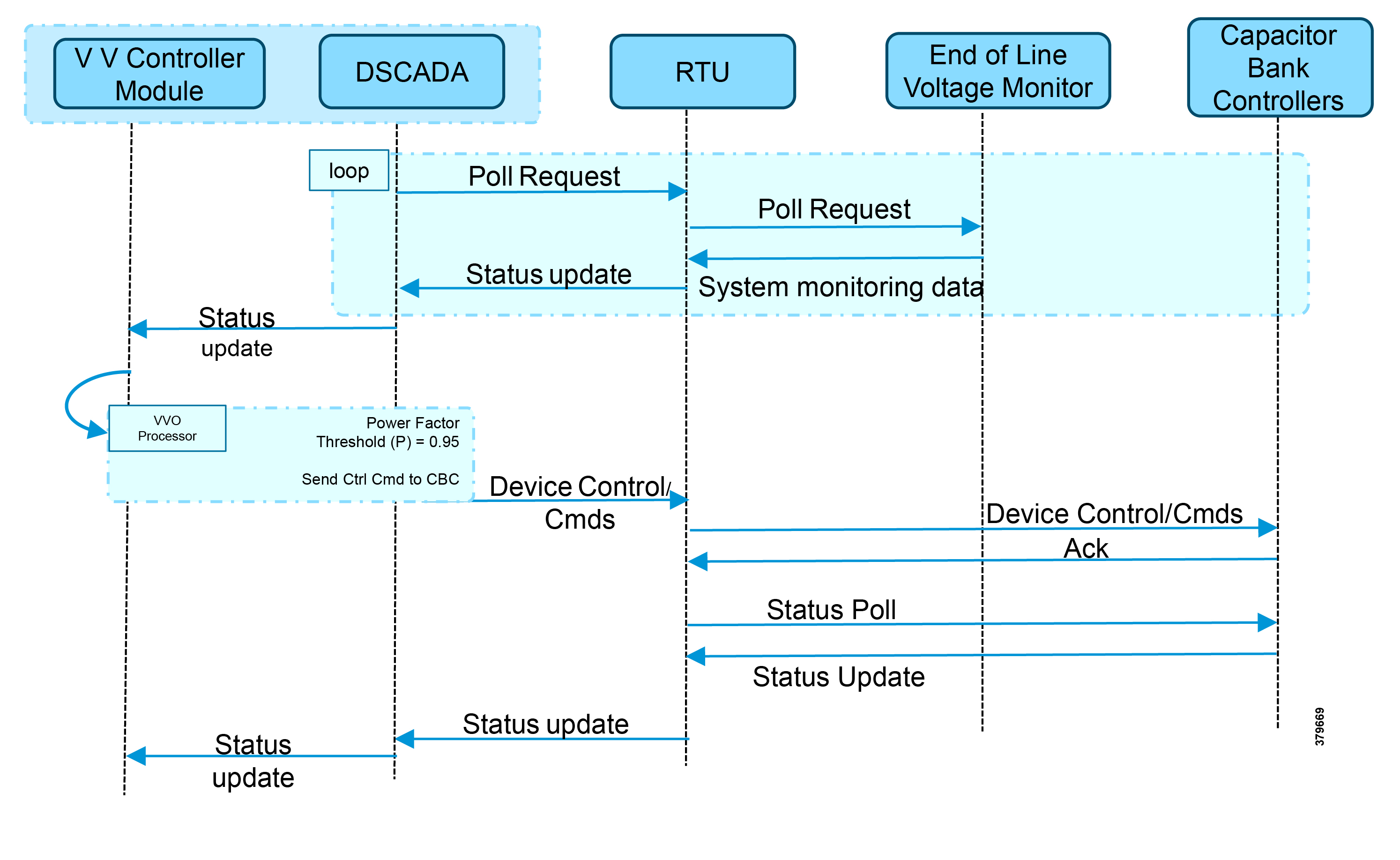
1.![]() Event class data poll to the following devices from RTU:
Event class data poll to the following devices from RTU:
–![]() Substation meter, poll measured Value (Short Floating Point) registers (0 to 4)
Substation meter, poll measured Value (Short Floating Point) registers (0 to 4)
–![]() All CBC(s), poll measured Value (Short Floating Point) (0) and double point command(0)
All CBC(s), poll measured Value (Short Floating Point) (0) and double point command(0)
–![]() End-of-line voltage monitor, poll measured Value (Short Floating Point) register (0)
End-of-line voltage monitor, poll measured Value (Short Floating Point) register (0)
2.![]() The Volt/VAR Optimization processor processes the data received from the devices and makes a control command decision based on the power factor calculation.
The Volt/VAR Optimization processor processes the data received from the devices and makes a control command decision based on the power factor calculation.
3.![]() The control command is sent to RTU via SCADA to CBCs to close the Capacitor Bank Controller N by writing in a Control Relay Output Block (CROB) command register in T104.
The control command is sent to RTU via SCADA to CBCs to close the Capacitor Bank Controller N by writing in a Control Relay Output Block (CROB) command register in T104.
4.![]() Event class data poll to the following devices from the RTU:
Event class data poll to the following devices from the RTU:
–![]() Substation meter, poll measured Value (Short Floating Point) registers (0 to 4)
Substation meter, poll measured Value (Short Floating Point) registers (0 to 4)
–![]() All CBC(s), poll measured Value (Short Floating Point) (0) and double point command(0)
All CBC(s), poll measured Value (Short Floating Point) (0) and double point command(0)
–![]() End-of-line voltage monitor, poll measured Value (Short Floating Point) register(0)
End-of-line voltage monitor, poll measured Value (Short Floating Point) register(0)
5.![]() All the above steps are repeated to all the CBCs on the feeder line to maintain a Power Factor value close to 1.
All the above steps are repeated to all the CBCs on the feeder line to maintain a Power Factor value close to 1.
Figure 6 Conservation Voltage Regulation (CVR)
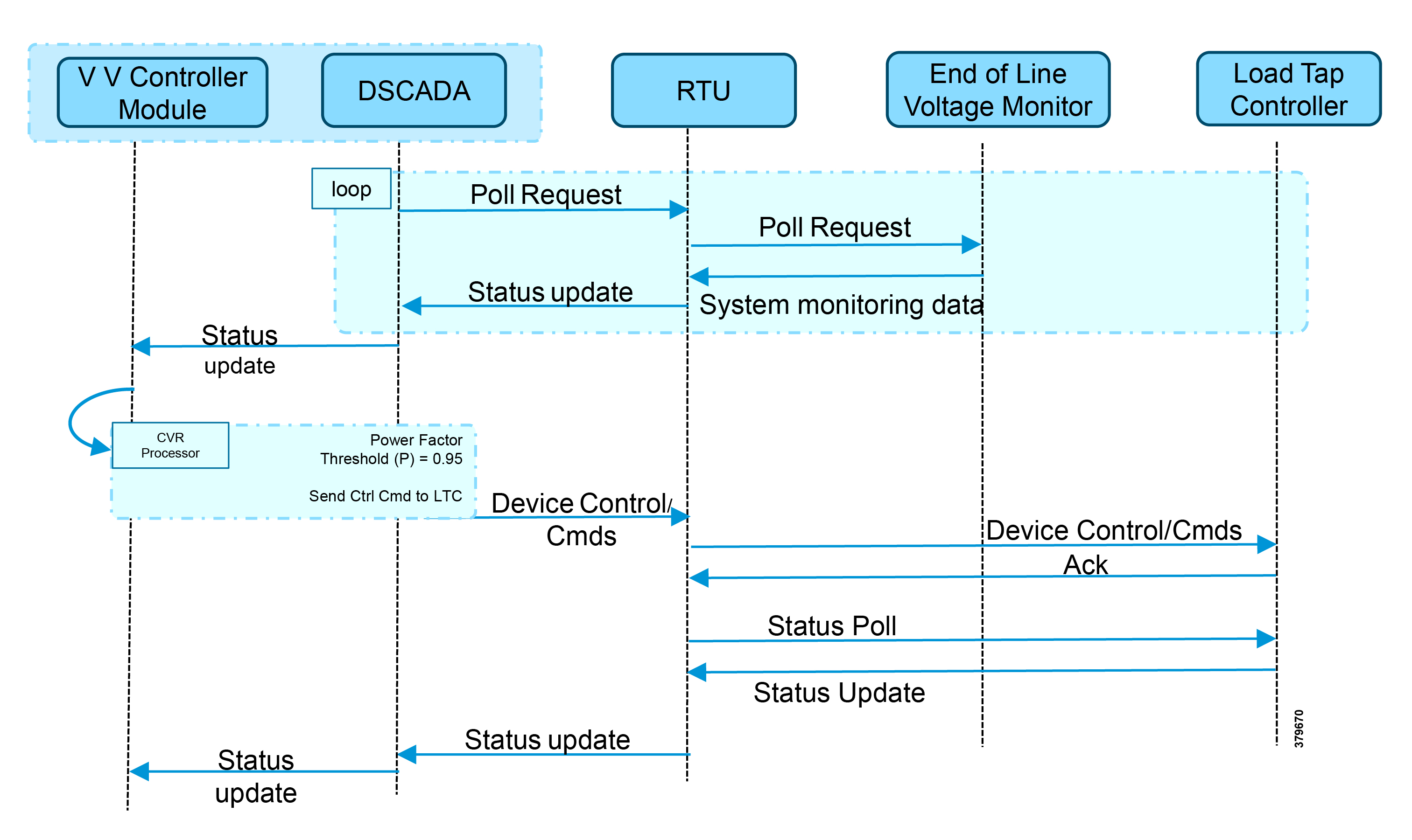
Figure 6 depicts the detail call flow involved in conservation voltage regulation.
1.![]() Event class data poll to the below devices from RTU:
Event class data poll to the below devices from RTU:
–![]() Substation meter, poll measured Value (Short Floating Point) registers (0 to 4)
Substation meter, poll measured Value (Short Floating Point) registers (0 to 4)
–![]() All CBC(s), poll measured Value (Short Floating Point) (0) and double point command (0)
All CBC(s), poll measured Value (Short Floating Point) (0) and double point command (0)
–![]() End-of-Line voltage monitor, poll measured Value (Short Floating Point) register (0)
End-of-Line voltage monitor, poll measured Value (Short Floating Point) register (0)
2.![]() The Volt/VAR Optimization processor processes the data received from the devices and makes a control command decision based on the power factor calculation.
The Volt/VAR Optimization processor processes the data received from the devices and makes a control command decision based on the power factor calculation.
3.![]() Control command is sent to RTU via SCADA to the load tap controller to lower/raise LTC by writing in a Control Relay Output Block (CROB) command register in T104.
Control command is sent to RTU via SCADA to the load tap controller to lower/raise LTC by writing in a Control Relay Output Block (CROB) command register in T104.
4.![]() Event class data polls to the following devices from RTU:
Event class data polls to the following devices from RTU:
–![]() Substation meter, poll measured Value (Short Floating Point) registers (0 to 4)
Substation meter, poll measured Value (Short Floating Point) registers (0 to 4)
–![]() All CBC(s), poll measured Value (Short Floating Point) (0) and double point command(0)
All CBC(s), poll measured Value (Short Floating Point) (0) and double point command(0)
–![]() End-of-Line voltage monitor, poll measured Value (Short Floating Point) register (0)
End-of-Line voltage monitor, poll measured Value (Short Floating Point) register (0)
5.![]() The above steps are repeated to maintain a Power Factor value close to 1 along the feeder line.
The above steps are repeated to maintain a Power Factor value close to 1 along the feeder line.
Fault, Location, Isolation, Service Restoration (FLISR)
FLISR Use Case and Benefits
FLISR is the process for dealing with fault conditions on the electrical grid. The following occurs as part of this process:
1.![]() Detects (and locates) faults
Detects (and locates) faults
2.![]() Isolates the faults to the smallest segment of the grid possible
Isolates the faults to the smallest segment of the grid possible
3.![]() Restores as much service as possible while the fault is isolated
Restores as much service as possible while the fault is isolated
FLISR includes automatic sectionalizing and restoration and automatic circuit reconfiguration. These applications accomplish DA operations by coordinating operation of field devices, software, and dedicated communication networks in order to automatically determine the location of a fault and rapidly reconfigure the flow of electricity so that some or all of the customers can avoid experiencing outages. Because FLISR operations rely on rerouting power, they typically require feeder configurations that contain multiple paths to single or multiple other substations. This creates redundancies in the power supply for customers located downstream or upstream of a downed power line, fault, or other grid disturbance.
The benefits of FLISR include:
■![]() Consumers experience minimal outage.
Consumers experience minimal outage.
■![]() Utilities improve the System Average Interruption Duration Index (SAIDI) and the System Average Interruption Frequency Index (SAIFI) numbers and avoid financial penalties being levied by the regulator.
Utilities improve the System Average Interruption Duration Index (SAIDI) and the System Average Interruption Frequency Index (SAIFI) numbers and avoid financial penalties being levied by the regulator.
FLISR application control can be implemented in the following modes:
■![]() Supervised Mode-In supervised mode of operation, no automatic control, system delivers information to operator. Operator initiates manual control actions. Restoration time will be longer in this approach. Please refer to the Distribution Automation - Secondary Substation 1.0 Implementation Guide, which addresses this use case, at the following URL:
Supervised Mode-In supervised mode of operation, no automatic control, system delivers information to operator. Operator initiates manual control actions. Restoration time will be longer in this approach. Please refer to the Distribution Automation - Secondary Substation 1.0 Implementation Guide, which addresses this use case, at the following URL:
–![]() https://salesconnect.cisco.com/#/search/Secondary%2520Substation%2520Implementation%2520Guide/conten t
https://salesconnect.cisco.com/#/search/Secondary%2520Substation%2520Implementation%2520Guide/conten t
■![]() Semi Automatic Mode-A mix of automatic and supervised control is followed. The DA system automatically isolates the fault and performs the restoration part of upstream restoration. The upstream section is between the substation and the faulted section. Manual restoration operation is performed on the downstream section, which is between the fault section and the end of feeder. This guide will address this mode of operation. In this mode, communication happens between IEDs in field to the Distribution Management System (DMS) application residing in control center.
Semi Automatic Mode-A mix of automatic and supervised control is followed. The DA system automatically isolates the fault and performs the restoration part of upstream restoration. The upstream section is between the substation and the faulted section. Manual restoration operation is performed on the downstream section, which is between the fault section and the end of feeder. This guide will address this mode of operation. In this mode, communication happens between IEDs in field to the Distribution Management System (DMS) application residing in control center.
■![]() Fully Automatic Mode-Isolation and restoration happens automatically without any dispatcher intervention. Communication happens directly between a group of associated IEDs. Restoration is very fast (<1 second), but this mode is a complex approach to deploy.
Fully Automatic Mode-Isolation and restoration happens automatically without any dispatcher intervention. Communication happens directly between a group of associated IEDs. Restoration is very fast (<1 second), but this mode is a complex approach to deploy.
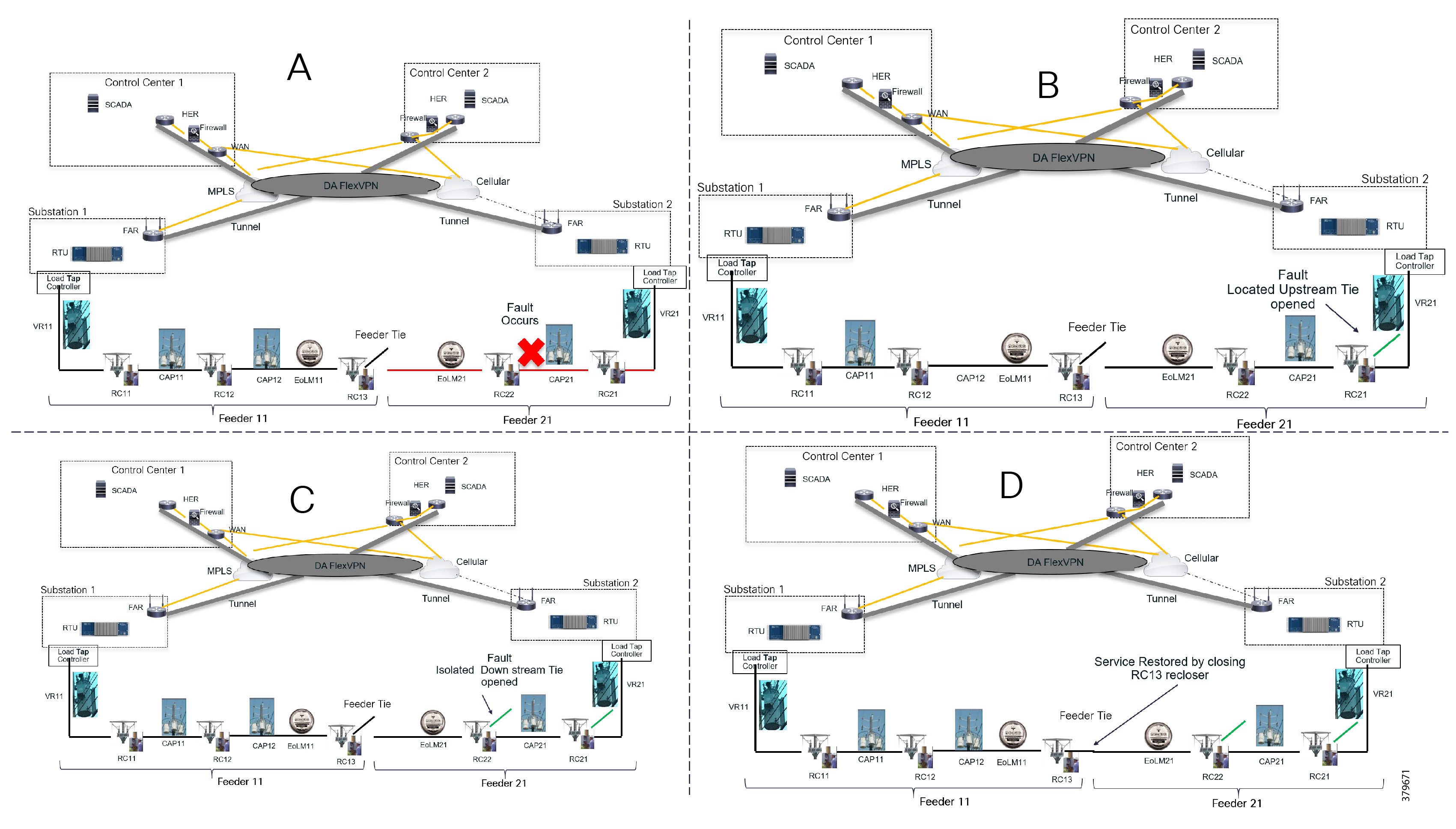
How FLISR Works
Figure 7 is divided into four parts (A,B,C, and D) to show how FLISR operations typically work.
■![]() In Example A of Figure 7, the FLISR system locates the fault, typically using line sensors that monitor the flow of electricity, measures the magnitudes of fault currents, and communicates conditions to other devices and grid operators.
In Example A of Figure 7, the FLISR system locates the fault, typically using line sensors that monitor the flow of electricity, measures the magnitudes of fault currents, and communicates conditions to other devices and grid operators.
■![]() Once located, FLISR opens switches on both sides of the fault: one immediately upstream and closer to the source of power supply (Example B of Figure 7), and one downstream and further away (Example C of Figure 7).
Once located, FLISR opens switches on both sides of the fault: one immediately upstream and closer to the source of power supply (Example B of Figure 7), and one downstream and further away (Example C of Figure 7).
■![]() The fault is now successfully isolated from the rest of the feeder. With the faulted portion of the feeder isolated, FLISR next closes the normally open tie switches to neighboring feeders. This re-energizes the unfaulted portion(s) of the feeder and restores services to all customers served by these unfaulted feeder sections from another substation/feeder (Example D of Figure 7).
The fault is now successfully isolated from the rest of the feeder. With the faulted portion of the feeder isolated, FLISR next closes the normally open tie switches to neighboring feeders. This re-energizes the unfaulted portion(s) of the feeder and restores services to all customers served by these unfaulted feeder sections from another substation/feeder (Example D of Figure 7).
FLISR Actors
■![]() Recloser-The circuit recloser is a self-contained device with a necessary monitoring circuit to detect and interrupt over-current conditions and automatically reclose the line.
Recloser-The circuit recloser is a self-contained device with a necessary monitoring circuit to detect and interrupt over-current conditions and automatically reclose the line.
■![]() Sectionalizing Switch or Remote Control Switch-Remote Controller Switches can be load break or fault interrupting devices.
Sectionalizing Switch or Remote Control Switch-Remote Controller Switches can be load break or fault interrupting devices.
■![]() Remote Fault Indicator-Used to detect faults.
Remote Fault Indicator-Used to detect faults.
■![]() Distribution Management System (DMS)-The DMS application residing in the DSO control center is an intelligent application, which is the brain of FLISR systems and which performs application circuit reconfiguration logic.
Distribution Management System (DMS)-The DMS application residing in the DSO control center is an intelligent application, which is the brain of FLISR systems and which performs application circuit reconfiguration logic.
Figure 8 depicts a parallel feeder distribution system. Two distribution feeders are common out of two different Secondary Substations and each feeder has a recloser associated with it. Remote Fault Indicators and remote control switches are distributed across both feeders. RCS3 3 is, by default, an open switch.
Figure 8 FLISR Parallel Feeders
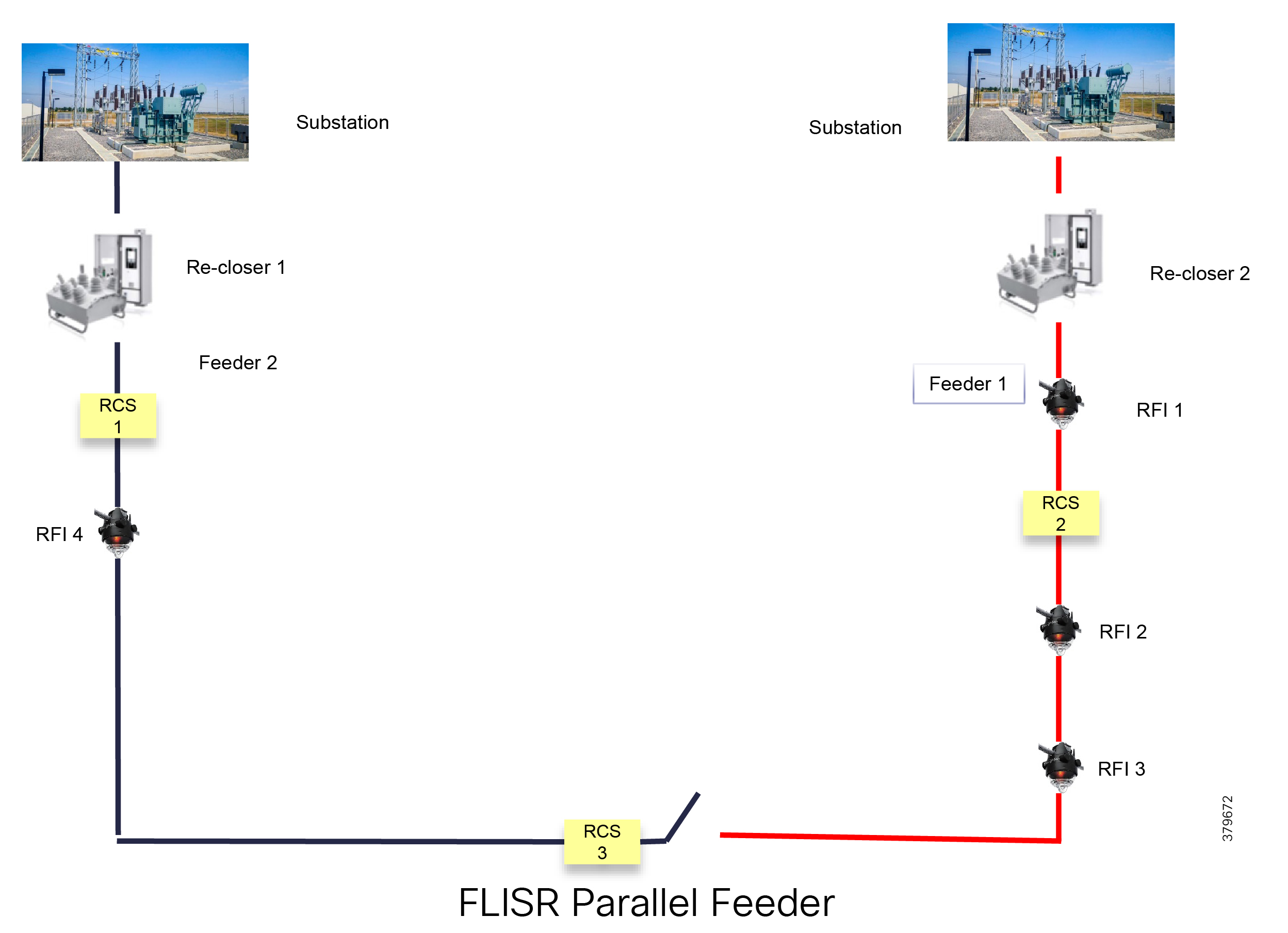
Figure 9 FLISR Application Communication Flow
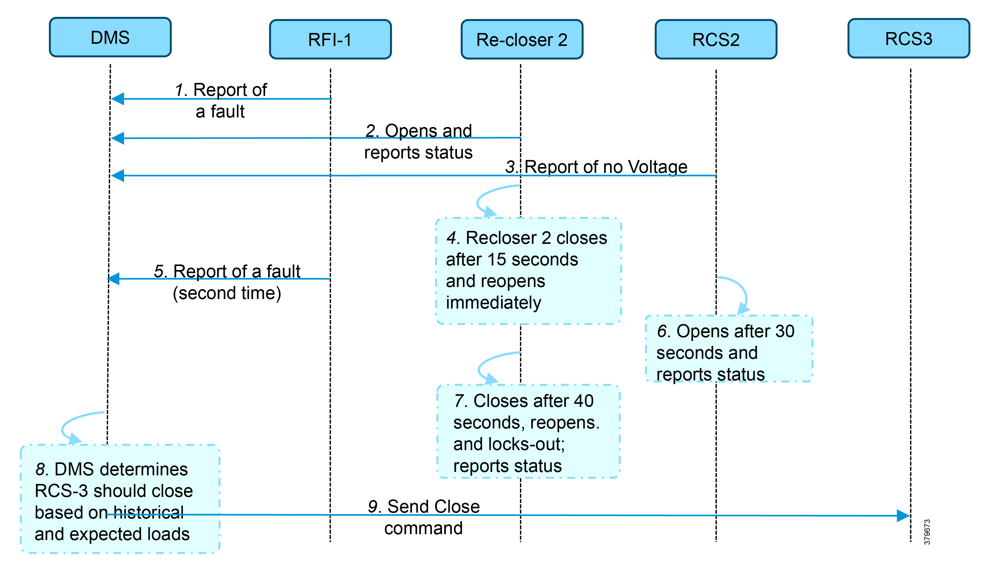
In Figure 9, the application flow can be observed happening directly from feeder devices to the DMS application in the DSO control center. The flow is summarized below:
■![]() Remote Fault Indicator (RFI) 1 reports to the Distribution Management System (DMS) whenever it encounters a fault.
Remote Fault Indicator (RFI) 1 reports to the Distribution Management System (DMS) whenever it encounters a fault.
■![]() Recloser2 opens and send a report to DMS when it encounters a temporary fault.
Recloser2 opens and send a report to DMS when it encounters a temporary fault.
■![]() Recloser2 opens and send a report to DMS when it encounters a permanent fault.
Recloser2 opens and send a report to DMS when it encounters a permanent fault.
■![]() Remote Control Switch (RCS) 2 reports no voltage status to DMS.
Remote Control Switch (RCS) 2 reports no voltage status to DMS.
■![]() RCS 2 opens when it encounters faults for second time and send a report to DMS.
RCS 2 opens when it encounters faults for second time and send a report to DMS.
■![]() DMS issues a close command to the RCS 3.
DMS issues a close command to the RCS 3.
■![]() DMS initiates a periodic poll (every minute) for the all feeder devices.
DMS initiates a periodic poll (every minute) for the all feeder devices.
■![]() DMS initiates a solicit periodic poll (every 5 minutes once) for all feeder devices.
DMS initiates a solicit periodic poll (every 5 minutes once) for all feeder devices.
DA Solution FLISR Use Case using SEL devices over CR mesh
Cisco Resilient (CR) mesh solution provides a reliable communication infrastructure, with bandwidth capacity and low latency that meets the DA use case performance requirements.
Schweitzer Electric Engineering Laboratories (SEL) is one of the major utility grid equipment and DA solution vendor in North America. Cisco and Schweitzer Engineering Laboratories (SEL) have collaborated on joint validation of FLISR use case over Cisco CR mesh. This joint validation used Fault Location Isolation and Service Restoration (FLISR) products from SEL operating over Cisco Resilient Mesh. Operational measurements such as trip time, data alignment, service restoration and operational consistency were recorded and the application was found to work very well over CR mesh.
This section provides guidance to utilities that they could privately own and operate a FAN radio network in the ISM 902-928 MHz band, such as Cisco Resilient Mesh, as a multi-service solution working well with Distribution Automation applications. Cisco has committed to validate the major DA use cases like FLISR within their indoor labs and outdoor pilot locations.
Schweitzer Electric Laboratories (SEL) has a comprehensive solution for the DA FLISR application that can be deployed in centralized architecture. The solution uses a controller device to provide advanced restoration capabilities that can be located in the control center. Combined with Cisco Resilient Mesh communication infrastructure the FLISR application can operate in fully automatic mode.
The SEL equipment listed below is used for Validation:
■![]() SEL Real-Time Automation Controller (RTAC)
SEL Real-Time Automation Controller (RTAC)
■![]() SEL Advanced Recloser Control (SEL-651R)
SEL Advanced Recloser Control (SEL-651R)
Cisco Resilient Mesh and SEL FLISR Architecture
Cisco resilient mesh and SEL FLISR architecture are shown in Figure 10. SEL FLISR controller device deployment follows a centralized FLISR architecture. The SEL FLISR controller devices are the outstation devices. These outstation devices connect to Cisco IR510 DA gateways, enabling the communication path. Cisco CR mesh comprising IR510, IR530 can be aggregated at a CGR1000 series of routers, usually located in the substation/along the feeder. The CGR1000 series of routers can talk to the control center over Private WAN (or) Public Cellular and fiber networks. Cisco Resilient mesh provides communication infrastructure to the SEL FLISR Architecture.
Figure 10 Cisco Resilient Mesh and SEL FLISR Architecture
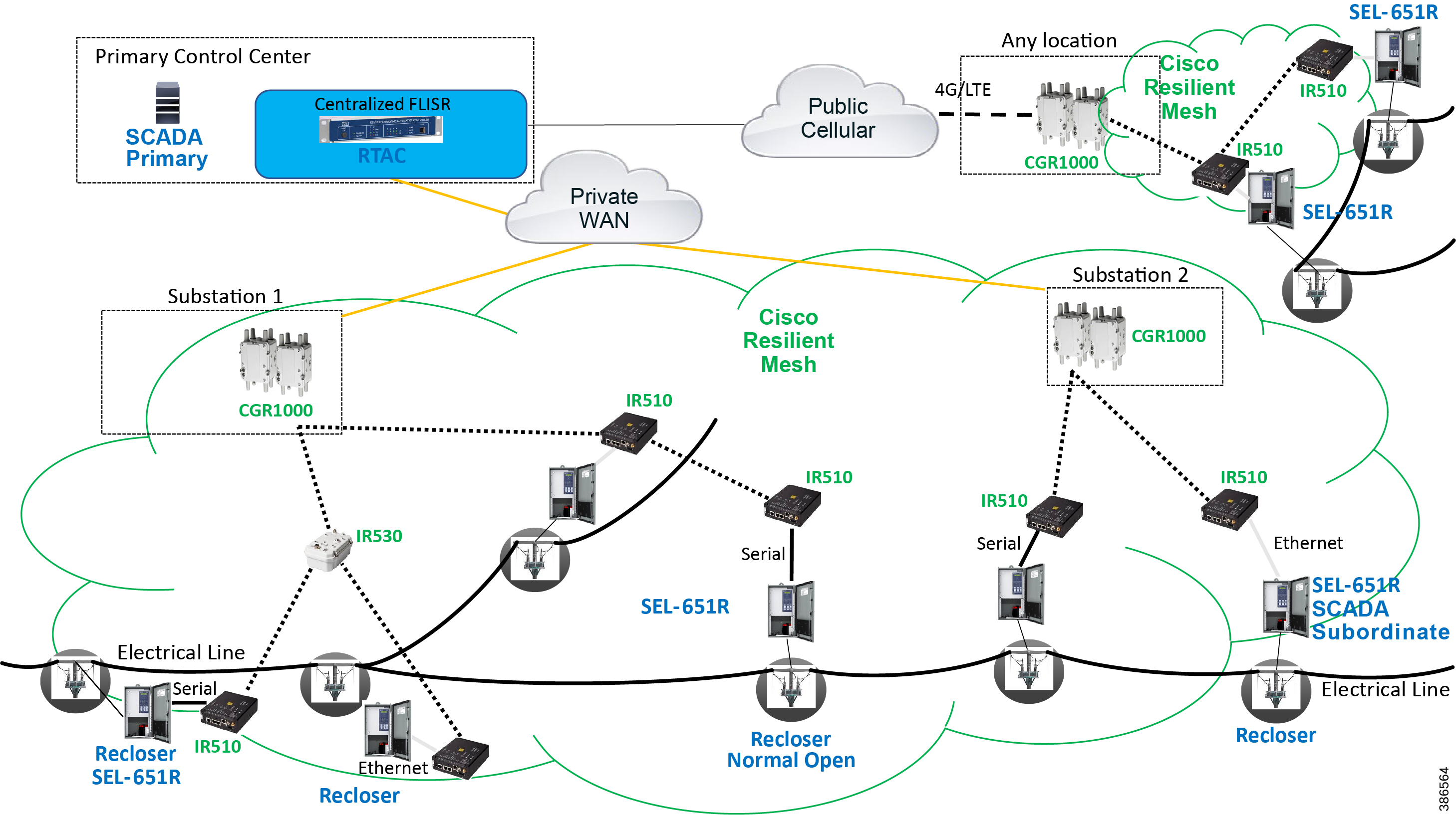
The SEL reclosers connect to the Cisco Resilient Mesh Industrial Routers (IR510) using Ethernet.
The Cisco IR510 DA gateways establish a reliable mesh wireless network based on signal propagation radio design. For instances where the radio signal cannot cover a certain area or signal levels are weak, Cisco Range Extenders (IR530) can be deployed to increase signal coverage for that area. CR mesh based on ISM 902-928MHz and IEEE802.15.4g/e standard using OFDM modulation with a physical data rate up to 1.2 Mbps can support the performance requirements of the FLISR application.
The SEL and Cisco DA solutions help utilities lower the SAIDI (System Average Interruption Duration Index) and SAFI (System Average Interruption Frequency Index) performance metrics which reflects the reliability of their Power Distribution network.
DNP3/IP messages between the SEL-651R recloser and the SEL controller are reliable routed through the mesh network via the most optimal path to the field area border router, such as Cisco CGR 1000 router, known as the mesh exit point, and then via either a fiber network or Cellular network to the Control Center location.
The SEL FLISR solution can also be deployed in a Centralized architecture where one or more RTAC devices are installed in the Control Center and each controller services an area that is not necessarily bonded to a substation service area. This approach has a lower deployment cost.
The Distribution Automation system consists of a DA controller (DAC) that communicates with multiple recloser controls, switch controls, feeder relays, and a wide range of other intelligent electronic devices (IEDs). The DAC is implemented on the SEL Real-Time Automation Controller (RTAC) family of controllers. The DAC can be applied to a wide variety of distribution network arrangements. The DACS addresses two major control objectives for the power distribution system: automatic reconfiguration (AR) and dynamic feeder optimization (DFO). This design will focus on the automatic reconfiguration since it has more stringent communications requirements.
The DAC functions to detect permanent fault and open-phase conditions on the distribution network. The DAC will act to isolate the affected zone of the feeder and restore power to the unaffected zones of the feeder from the normal source and from alternative sources, if available. The DAC also functions to detect overload conditions on the distribution network. The DAC will act to mitigate overloads by transferring load to adjacent feeders or by load shedding if alternative capacity is unavailable. In addition, the DAC functions to detect station events and loss-of-source events. The DAC will act to isolate the affected station and restore power to the unaffected feeders from alternative sources, if available.
DA FLISR Use case with SEL
Solution Overview
Cisco Resilient Mesh networks can support the SEL FLISR application over a variety of topologies and places in the network. Contents of the subsequent sections is summarized below:
These topologies were considered during the joint validation activity:
Each topology is described with the following:
■![]() FLISR Topology-based one-line diagram (with segment division)
FLISR Topology-based one-line diagram (with segment division)
■![]() FLISR Topology-based SEL device to Cisco device mapping diagram
FLISR Topology-based SEL device to Cisco device mapping diagram
■![]() FLISR Topology-based SEL device to Cisco device mapping table.
FLISR Topology-based SEL device to Cisco device mapping table.
FLISR Fault scenarios are described below:
For the SEL FLISR use case in Rural/Urban topology, the following faults in the power line are considered:
Each of these FLISR Fault scenarios are considered in three states:
SEL FLISR Use case Validation Call Flow Sequence
The call flow sequence of the SEL FLISR use case validation uses the DNP3/IP application protocol. UDP is the recommended protocol at the transport layer to transport the DNP3/IP messages. The two topologies for SEL FLISR use case validation are:
Figure 11 FLISR - Call Flow Event Sequence - Application DNP3 between DAC and IED
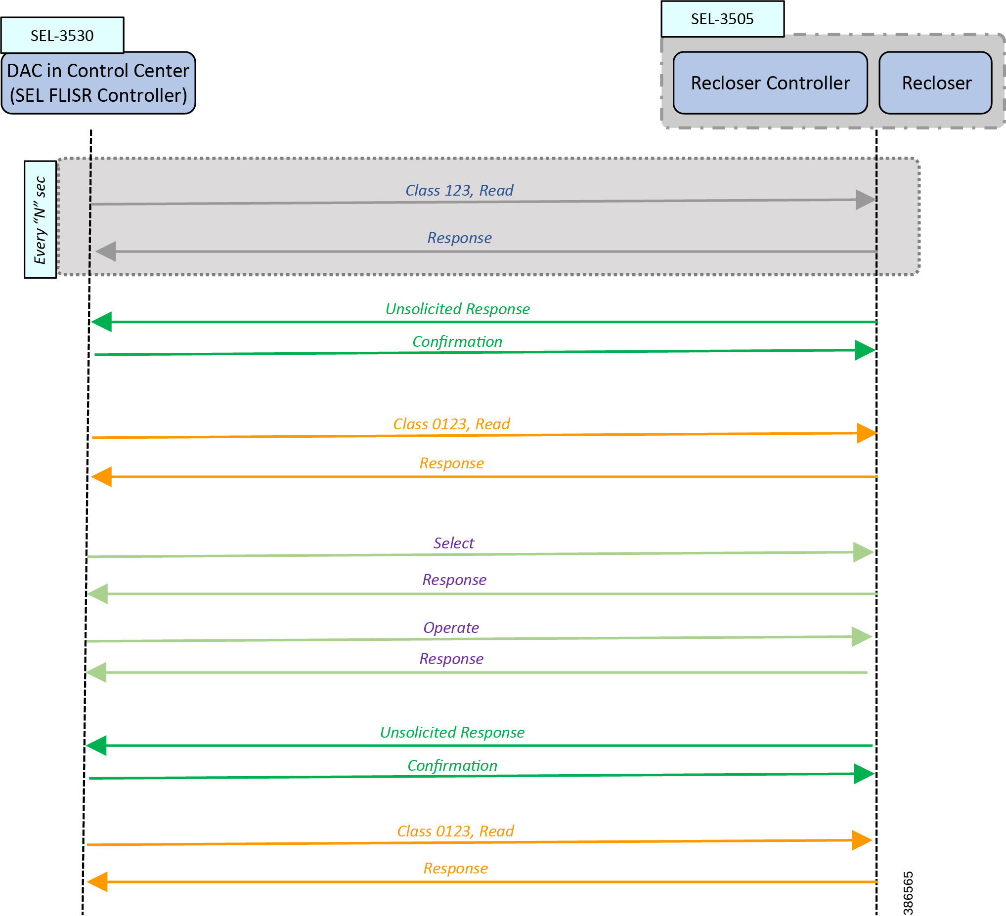
The Call flow sequence in Figure 11 is categorized into these major blocks:
■![]() Unsolicited Response/Confirmation
Unsolicited Response/Confirmation
Of the Commands listed above, Class123 is a periodic command; others are event-driven commands. For example, Unsolicited Response is an event-driven command.
Class0123 is used as periodic command, but with a longer duration of polling interval. The interval is once every 30 minutes in case of FLISR over radio.
In Figure 11, the Class123 event is configured to operate periodically every “N” seconds.
In the following FLISR Fault scenarios, these faults are introduced in specific segments of the Urban/Rural topology:
When these faults are introduced into the SEL FLISR (Urban/Rural) topology into a particular segment, the SEL device in the affected segment raises “Unsolicited Response” messages to the SEL FLISR Controller (DAC), located in the control center.
DAC then sends an acknowledgment “Confirmation” message to the corresponding SEL device (Recloser Controller).
The “Unsolicited Response” conveys a change of state in the network. The SEL DA FLISR Controller performs “Class0123 Read” of all the related set of SEL devices to get the holistic view of the SEL FLISR Topology status.
In response to the Class0123 read request from the DAC, the SEL devices then respond with “Class 0123 Response” to the SEL FLISR Controller. The set of related SEL devices includes devices in the affected feeder section(s) and any adjacent sections connected with a normally open point.
The SEL FLISR Controller performs a FLISR computation, and decides which SEL recloser devices it must open, and which SEL recloser devices it must close. To accomplish this, the SEL FLISR Controller uses a “Select” message, followed by “Operate” message. Alternatively, the DA FLISR controller could directly perform “Operate” commands instead of Select before Operate. For each of the “Select” or “Operate” messages from the SEL FLISR Controller, the Recloser responds back with “Response” message.
Recommendation from SEL is to use direct Operate, as Select before Operate is a remnant of the past when auxiliary relays were used. This serves an additional purpose of reducing the load on the mesh by a fraction. Bandwidth conserved is the bandwidth earned for other application traffic.
When the status of the SEL device changes, the SEL recloser controller updates the SEL FLISR DA Controller device using “Unsolicited response” message, which is acknowledged back by DAC using “Confirmation” message.
When the SEL FLISR DA Controller requires a holistic view of the current status of the topology, it sends “Class0123 Read” to all the related SEL recloser controller devices. The current status of the related device is updated back in the corresponding “Class0123 Response” message sent by SEL recloser controller device to the DAC. The set of related SEL devices includes devices in the affected feeder section(s) and any adjacent sections connected with a normally open point.
This completes the SEL FLISR Event call flow sequence. This sequence could happen over SEL FLISR Urban/Rural topology, which are discussed in upcoming sections.
Note: Throughout this section, the terms DAC and SEL FLISR DA Controller are used interchangeably.
Cisco SEL FLISR Use case – Urban Topology
FLISR Topology, Urban Area - One-line diagram:
Figure 12 FLISR Topology, Urban Area – One-line diagram
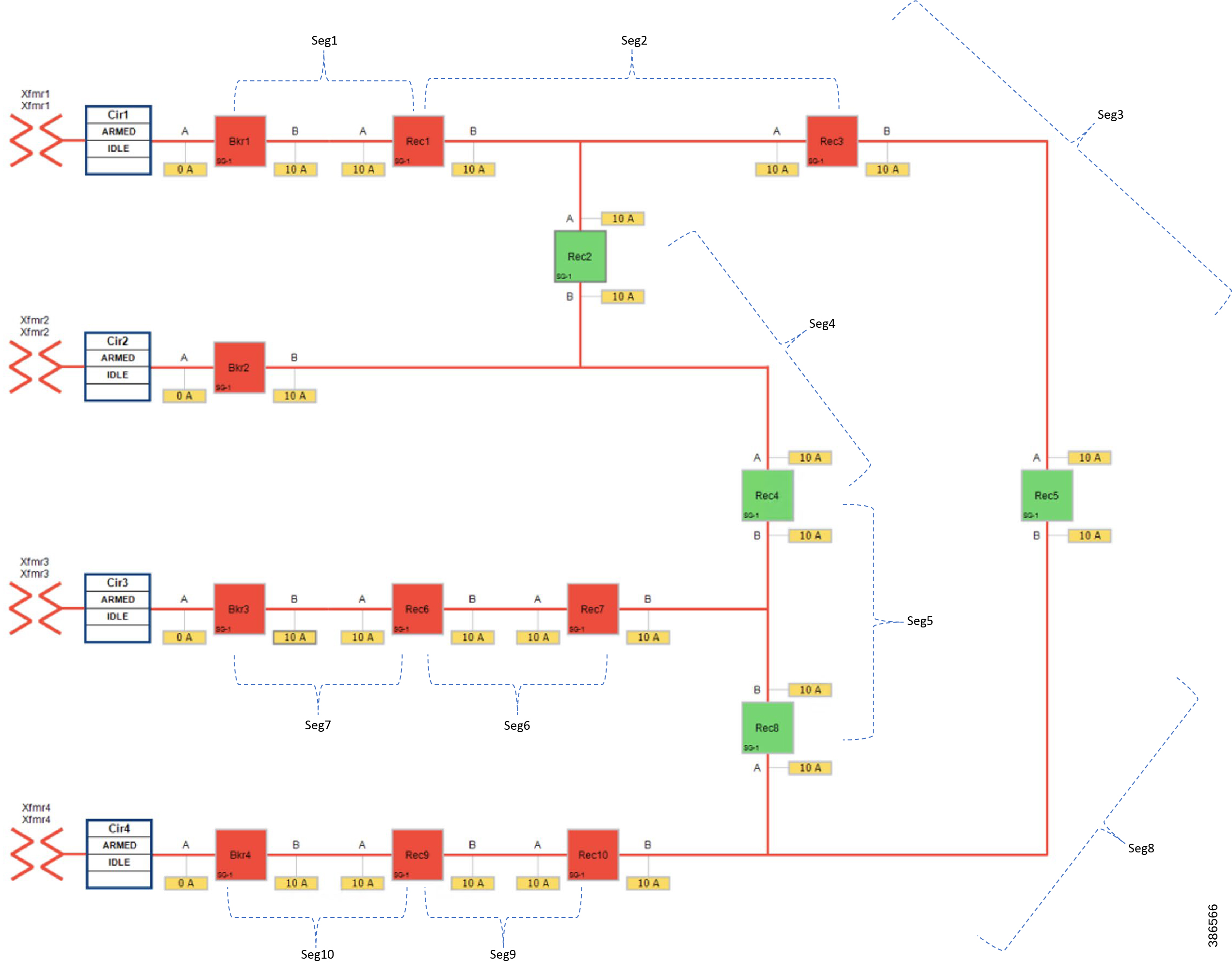
The one-line diagram in Figure 12 describes the FLISR topology in urban area. The topology has been divided into ten segments (Seg1, Seg2,..., Seg10). Red boxes represent Energized (Closed) reclosers, while green boxes representing unenergized (Normally open) reclosers.
■![]() Seg 1, Seg 2 and Seg 3 were energized from Transformer1
Seg 1, Seg 2 and Seg 3 were energized from Transformer1
■![]() Seg 4 was energized from Transformer2
Seg 4 was energized from Transformer2
■![]() Seg 5, Seg 6, Seg 7 were energized from Transformer3
Seg 5, Seg 6, Seg 7 were energized from Transformer3
Urban FLISR Topology - SEL device to Cisco device mapping
Figure 13 FLISR Topology, Urban Area – SEL reclosers to Cisco device mapping

This topology captures the 1-to-1 mapping of SEL recloser devices to Cisco IR510 devices. The controller device is located in the Primary control center. CR Mesh is aggregated at the Field Area Network aggregator using CGR1000 series router which can be located in the substation. The communication between substation and control center can be over public/private WAN. The SEL device is positioned behind IR510 and connected using Ethernet.
■![]() The device representing DA CONTROLLER (SEL3530-2) is located in Primary control center.
The device representing DA CONTROLLER (SEL3530-2) is located in Primary control center.
■![]() The device representing Recloser 9 (SEL3505-9) is associated with IR510-13.
The device representing Recloser 9 (SEL3505-9) is associated with IR510-13.
■![]() The device representing Recloser 6 (SEL3505-6) is associated with IR510-12.
The device representing Recloser 6 (SEL3505-6) is associated with IR510-12.
■![]() The device representing Recloser 1 (SEL3505-1) is associated with IR510-1.
The device representing Recloser 1 (SEL3505-1) is associated with IR510-1.
■![]() The device representing Recloser 10 (SEL505-10) is associated with IR510-23
The device representing Recloser 10 (SEL505-10) is associated with IR510-23
■![]() The device representing Recloser 7 (SEL505-7) is associated with IR510-22
The device representing Recloser 7 (SEL505-7) is associated with IR510-22
■![]() The device representing Recloser 2 (SEL505-2) is associated with IR510-21
The device representing Recloser 2 (SEL505-2) is associated with IR510-21
■![]() The device representing Recloser 8 (SEL505-8) is associated with IR510-33
The device representing Recloser 8 (SEL505-8) is associated with IR510-33
■![]() The device representing Recloser 4 (SEL505-4) is associated with IR510-32
The device representing Recloser 4 (SEL505-4) is associated with IR510-32
■![]() The device representing Recloser 5 (SEL505-5) is associated with IR510-42
The device representing Recloser 5 (SEL505-5) is associated with IR510-42
■![]() The device representing Recloser 3 (SEL505-3) is associated with IR510-4
The device representing Recloser 3 (SEL505-3) is associated with IR510-4
The following table captures the Individual mapping of the SEL device with the Cisco Mesh and the mesh depth. The mapped pair of SEL/Cisco device is located on the mesh. The FLISR Controller (SEL3530-2) is located in the control center. The rest of the SEL devices (SEL 3505) are located along the substation and feeder.
Table 1 FLISR Urban Topology Components
The next section discusses a few different types of FLISR Faults (Fault with LockOut, Open Phase, Loss of Source), each of them in three different states (Normal, Fault, Restored).
FLISR Fault scenario - Fault with Lock Out
In the case of a permanent fault, the recloser goes into lockout state until the fault is resolved by utility technician. For example, when a tree branch falls on the distribution line and conductors break each recloser that noticed the fault will trip and send an unsolicited DNP3/IP message upstream to the DA FLISR Controller. This covers the Fault Location identification phase of FLISR.
When the fault location is identified, the DA controller gets the overall current status of the topology by sending a Class0123 poll to all the related reclosers. This group includes devices in the affected feeder section(s) and any adjacent sections connected with a normally open point. Then the DAC performs the FLISR restoration computation, and proceeds to the FLISR restoration phase.
In the FLISR restoration phase, the DA Controller sends DNP3/IP commands to the respective reclosers that needs to change state in order to restore the services. Once the DA FLISR controller finishes the reconfiguration, it performs one round of Class0123 polling to ensure the stability. This covers the Fault Isolation and Service Restoration phase of the FLISR.
The Urban One-line topology in normal operational state is shown below.
Figure 14 Urban Topology - Fault with Lockout - Normal State

When a fault is introduced in Segment 2 between Recloser1 and Recloser2, at point B, recloser1 on the segment changes its state from Normally Closed state (NC) to Open state. This results in loss of power to the segments shown in the figure below.
■![]() Segment 2 (where the fault occurred)
Segment 2 (where the fault occurred)
■![]() Segment 3 (where the fault did not occur)
Segment 3 (where the fault did not occur)
Figure 15 Urban Topology - Fault with Lockout - Fault State

In the faulted state, customers in the region in segment 2 experience a loss of power; customers in the non-faulted region in segment 3 are also experiencing the loss of power.
The moment the fault occurred, recloser1 that detects the fault (in segment2) changes its state from Close to Open and enters Lockout state. The DA FLISR controller then sends Class0123 polling after one recloser goes into Lockout state, indicating there is a permanent fault.
Points to note in the topology:
■![]() Recloser1: Should change the state from Normally Closed state to Open state and locked out.
Recloser1: Should change the state from Normally Closed state to Open state and locked out.
■![]() Recloser3: might continue to be in Closed state, but no power on the feeder line.
Recloser3: might continue to be in Closed state, but no power on the feeder line.
■![]() Consumers of power located in Segment2 and Segment3 would experience loss of service.
Consumers of power located in Segment2 and Segment3 would experience loss of service.
The FLISR SEL DA controller response sequence is outlined below:
1.![]() To Change the state of the Recloser 3 located between segment 2 and 3 from Normally closed to Open
To Change the state of the Recloser 3 located between segment 2 and 3 from Normally closed to Open
2.![]() To change the state of the Recloser 5(located between segment 3 & 8) from Normally Open state to Closed state, provided transformer 4 doesn’t get overloaded to serve segment 3.
To change the state of the Recloser 5(located between segment 3 & 8) from Normally Open state to Closed state, provided transformer 4 doesn’t get overloaded to serve segment 3.
This results in energizing segment 3 with power source from transformer4 feeder.
Figure 16 Urban Topology - Fault with Lockout - Restored State
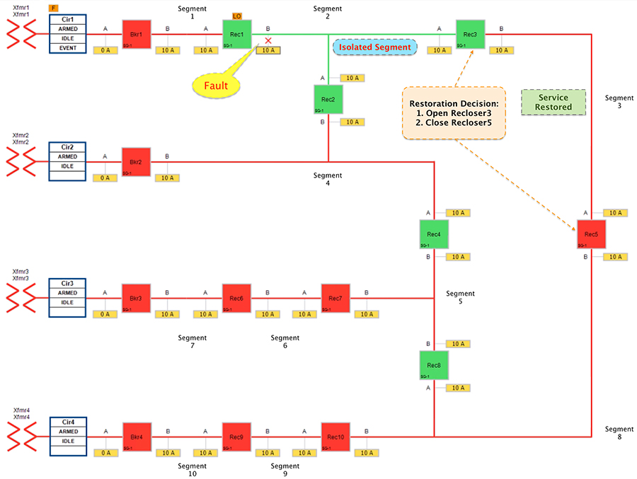
The results to customers is as follows.
■![]() Customers in non-faulty region in segment 3 would have power service restored with the help of FLISR.
Customers in non-faulty region in segment 3 would have power service restored with the help of FLISR.
■![]() Due to Fault isolation, power outage is restricted to Customers in the faulty (and isolated) region in segment 2.
Due to Fault isolation, power outage is restricted to Customers in the faulty (and isolated) region in segment 2.
■![]() Fault Location Identification - identified in segment2.
Fault Location Identification - identified in segment2.
■![]() Service Restoration – Restoring the power to non-faulty segment (segment 3).
Service Restoration – Restoring the power to non-faulty segment (segment 3).
■![]() Isolation - Fault has been restricted to affected customers in segment 2 alone.
Isolation - Fault has been restricted to affected customers in segment 2 alone.
FLISR Fault scenario – Open Phase
An Open Phase fault applies to three-phase circuits, where one of the line voltage is lost. One cause could be due to a bad or loose street pole line jumper that interrupts the line. The loss of voltage will trigger a DNP3/IP unsolicited message to the DA Controller. The DA controller then initiates the necessary action, similar to FLISR Fault scenario - Fault with Lockout.
Figure 17 FLISR Urban Topology – Open Phase - Normal State
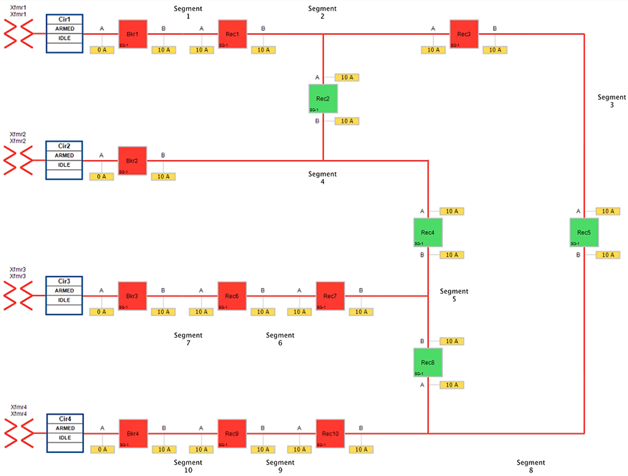
Figure 17 portrays the normal state of the FLISR Urban topology. Take note of segment 8. Reclosers corresponding to this segment are Recloser 5, Recloser 8 and Recloser 10. Of these three reclosers, Reclosers 5 & 8 are Normally Open. Recloser 10 is in Closed state, thus energizing segment 8 with the power source from Transformer 4.
The Open Phase Fault occurs in point B of recloser 10, as highlighted in below figure XX, with a red “X”.
Figure 18 FLISR Urban Topology – Open Phase - Fault State
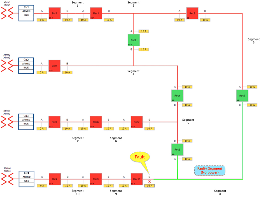
Figure 18 portrays the fault state of the FLISR Urban topology. When fault occurred in segment 8 customers experience loss of power. The participating reclosers report the change of state using DNP3/IP Unsolicited Response message to the FLISR DA controller located in the control center.
The DA controller sends DNP3/IP Class0123 polling from all the related reclosers in the FLISR Urban topology to get a holistic view of the topology status. The set of related SEL devices includes devices in the affected feeder section(s) and any adjacent sections connected with a normally open point.
Note: In comparison to the FLISR Fault in the Fault with Lockout scenario, while in fault state only customers in the faulty segment 8 experience loss of power. All the other segments have power.
Segment 8 is chosen to illustrate the following point. In cases where no other segment is affected, other than the faulty segment, the FLISR restoration action can be to do nothing.
Figure 19 FLISR Urban Topology – Open Phase - Restored State
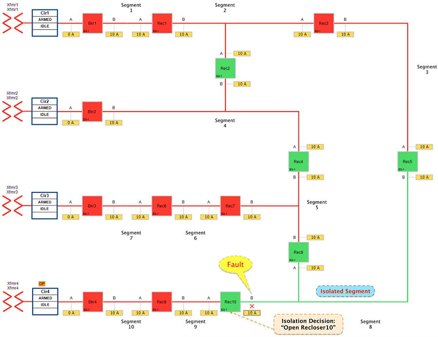
■![]() The DA controller makes the decision to change the state of the Recloser10 from normally closed state to Open.
The DA controller makes the decision to change the state of the Recloser10 from normally closed state to Open.
■![]() Due to Fault isolation, power outage is restricted to customers in the faulty region in segment 8.
Due to Fault isolation, power outage is restricted to customers in the faulty region in segment 8.
■![]() No Customers in any other segment are affected.
No Customers in any other segment are affected.
■![]() Fault Location Identification - identified in segment8.
Fault Location Identification - identified in segment8.
■![]() Service Restoration – No FLISR restoration needed in this case. It is only the isolation of faulty segment.
Service Restoration – No FLISR restoration needed in this case. It is only the isolation of faulty segment.
■![]() Isolation - Fault has been restricted to affected customers in segment 8 alone.
Isolation - Fault has been restricted to affected customers in segment 8 alone.
FLISR Fault scenario – Loss of Source
Loss of source applies to fault that occurs within the substation yard. For example, a bus fault at the substation could cause an outage for the entire feeder originating from that substation. In this scenario, the relay within the substation will notify the SEL DA controller of the loss of power which will then initiate the restoration process.
Figure 20 Urban Topology – Loss of Source - Normal State
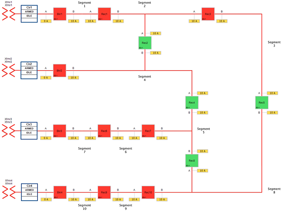
Figure 20 portrays the normal state of the FLISR Urban topology. Notice the feeder line from transformer 3 which includes segment 7, segment 6 and segment 5.
■![]() Reclosers 4 & 8 are Normally Open. Circuit Breaker3, Reclosers 6 & 7 are Closed.
Reclosers 4 & 8 are Normally Open. Circuit Breaker3, Reclosers 6 & 7 are Closed.
■![]() All the three segments (5,6 and 7) derive a power source from transformer3.
All the three segments (5,6 and 7) derive a power source from transformer3.
The third feeder transformer was taken out of service to simulate a loss of power. The substation feeder breaker (Brk3) tripped and all the downstream customers lost power.
Figure 21 Urban Topology – Loss of Source - Fault State
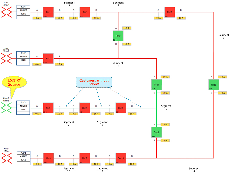
■![]() Reclosers 4 & 8 are still in Normally Open state.
Reclosers 4 & 8 are still in Normally Open state.
■![]() Circuit Breaker3, Reclosers 6 & 7 are in Closed state.
Circuit Breaker3, Reclosers 6 & 7 are in Closed state.
■![]() All the three segments (5,6 and 7) experiences loss of power, as transformer3 is out of service.
All the three segments (5,6 and 7) experiences loss of power, as transformer3 is out of service.
The circuit breaker and recloser devices sends DNP3/IP unsolicited message (about the loss of power) upstream to the SEL DA controller device located in the control center. The SEL DA controller performs DNP3/IP Class0123 polling from all the related reclosers in the FLISR Urban topology to get a holistic view of the current state of the topology.
The SEL FLISR DA Controller finds the most optimal way to restore the services and, in this case, it chooses to:
■![]() Change the Circuit breaker 3 from Closed state to Open state.
Change the Circuit breaker 3 from Closed state to Open state.
■![]() Change the Recloser8 state from Normal Open to Closed state.
Change the Recloser8 state from Normal Open to Closed state.
This would result in energizing segments (5,6 and 7) with power source from transformer4 feeder.
Figure 22 Urban Topology – Loss of Source - Restored State
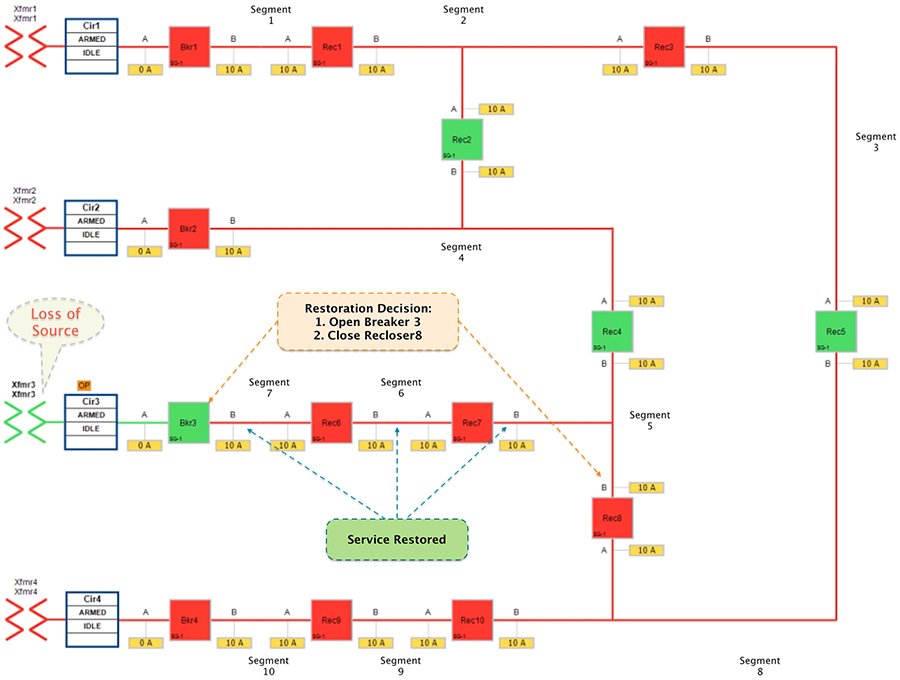
■![]() Customers in all the affected segments (5,6 and 7) would have power service restored with the help of FLISR.
Customers in all the affected segments (5,6 and 7) would have power service restored with the help of FLISR.
■![]() Due to Fault isolation, transformer3 is taken out of the picture. Affected segments are now served by power from transformer4.
Due to Fault isolation, transformer3 is taken out of the picture. Affected segments are now served by power from transformer4.
■![]() Fault Location - identified fault in transformer3.
Fault Location - identified fault in transformer3.
■![]() Isolation - Fault has been restricted to transformer3 and it has been taken out of service.
Isolation - Fault has been restricted to transformer3 and it has been taken out of service.
■![]() Service Restoration – Restored the power to affected segments using alternate power source (transformer4).
Service Restoration – Restored the power to affected segments using alternate power source (transformer4).
Cisco SEL FLISR Use case – Rural Topology
FLISR Topology – Rural Area - One-line diagram:
Figure 23 FLISR Topology (Rural Area) – One-line diagram
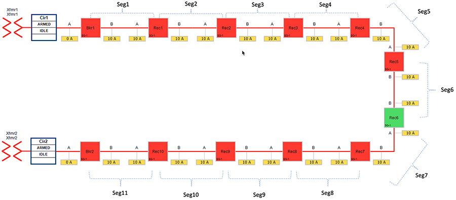
Figure 23 captures the one-line diagram of the FLISR topology in a Rural area. The topology has been divided into eleven segments (Seg1, Seg2,... Seg11). Red boxes represent Energized (Closed) power line, and green boxes represent unenergized (open) power line. Segments are energized as follows:
Rural FLISR Topology - SEL device to Cisco device mapping:
Figure 24 FLISR Topology (Rural Area) – SEL reclosers to Cisco device mapping diagram
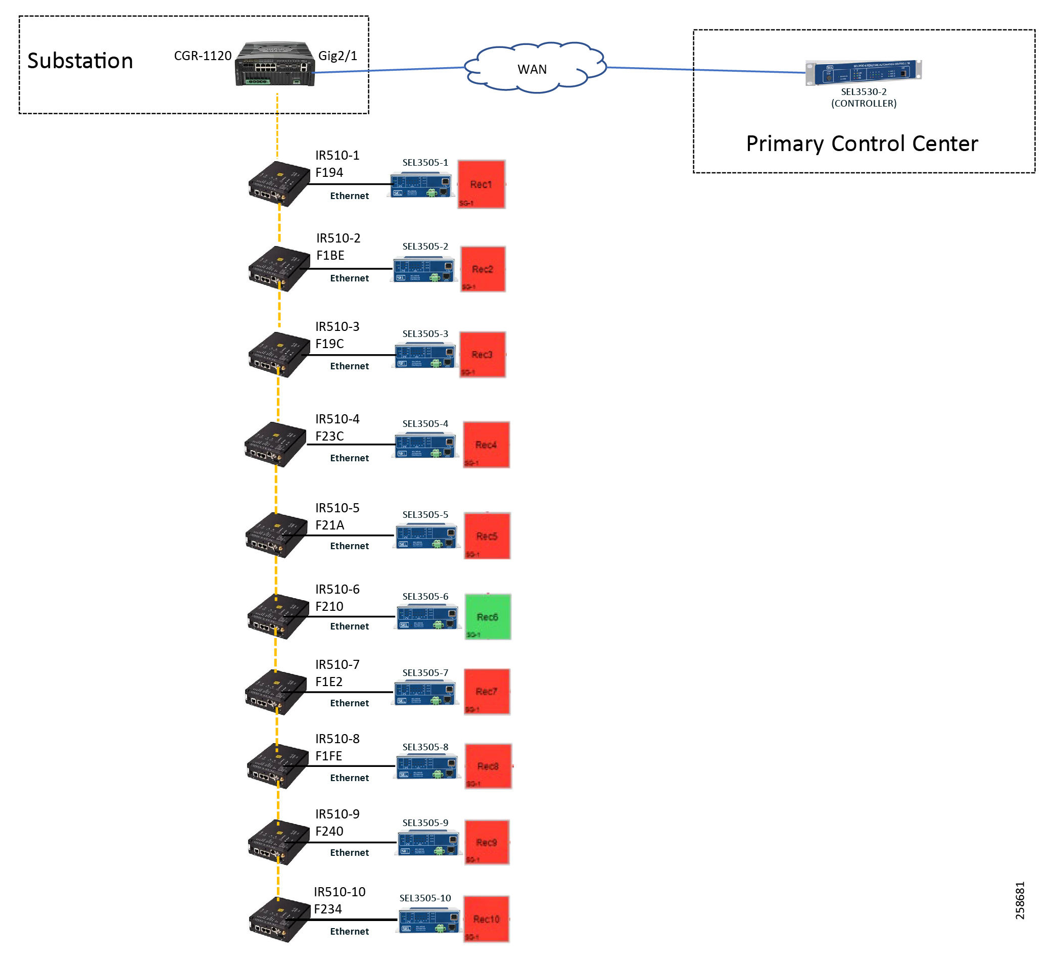
Figure 24 captures the 1-to-1 mapping of SEL recloser devices to Cisco IR510 devices. The DA controller device is located in the Primary control center. CR Mesh is aggregated at the Field Area Network aggregator using CGR1000 series router which can be located in the substation. The communication between substation and control center can be over public/private WAN. The SEL device is positioned behind IR510 and connected using Ethernet.
The following table captures the Individual mapping of the SEL device with Cisco Mesh device and the mesh depth. The mapped pair of SEL/Cisco devices is located on the mesh. FLISR Controller (SEL3530-2) is located in control center. Other SEL devices, SEL 3505s, are located along the substation and feeder.
Table 2 FLISR Rural Topology Components
A few different types of FLISR Faults such as Fault with LockOut, Open Phase, Loss of Source, each of them in three different states (Normal, Fault, Restored) are discussed.
SEL FLISR Rural Topology - FLISR Fault scenario - Fault with LockOut
This failure scenario in Rural topology is very much similar to “SEL FLISR Urban Topology - FLISR Fault scenario - Fault with LockOut”. From the SEL FLISR Use case point of view, there is not much difference. Affected segments sends DNP3/IP unsolicited messages to SEL FLISR DA Controller located in the control center, which in turns performs Class0123 polling to know the holistic view of the FLISR topology. Later, SEL DA controller performs the required restoration operations. However, the underlying topology of the Cisco RF mesh is different. Rural topology uses hierarchical multi-hop topology.
The Rural One-line topology in normal operational state looks like Figure 25 below.
Figure 25 Rural Topology - Fault with Lockout - Normal State

In above Figure 25:
■![]() Recloser 6 is in Normally Open (NO) state. Every other device is in closed state (the line is energized).
Recloser 6 is in Normally Open (NO) state. Every other device is in closed state (the line is energized).
■![]() Segments 1-6 are powered by feeder from transformer1
Segments 1-6 are powered by feeder from transformer1
■![]() Segments 7-11 are powered by feeder from transformer2
Segments 7-11 are powered by feeder from transformer2
When a fault gets introduced in Segment 3 (between Recloser2 and Recloser3), recloser 2 participating in that segment changes its state from Normally Closed state (NC) to Open state. This would result in loss of power to below segments (as shown in the figure below):
■![]() Segment 3 (between Recloser 2 and 3) - where the fault did occur
Segment 3 (between Recloser 2 and 3) - where the fault did occur
■![]() Segments 4-6 (between Recloser 3 and 6) - where the fault did not occur.
Segments 4-6 (between Recloser 3 and 6) - where the fault did not occur.
Figure 26 Rural Topology - Fault with Lockout - Fault State
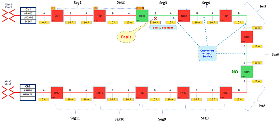
In this state, customers in the faulty region in segment 3 is experiencing loss of power. Along with them, customers in non-faulty regions belonging to segments 4-6 are also experiencing the loss of power.
The moment fault occurred, recloser2 participating in the segment (3) changes its state from Closed to Open. Meanwhile, following reclosers would send DNP3/IP unsolicited messages upstream to the SEL FLISR DA controller:
■![]() Recloser2 – conveys the fault.
Recloser2 – conveys the fault.
■![]() Reclosers (3-6) – conveys the loss of power.
Reclosers (3-6) – conveys the loss of power.
The SEL FLISR DA controller then performs Class0123 polling on every related recloser to get holistic view of the topology before making any restoration decision.
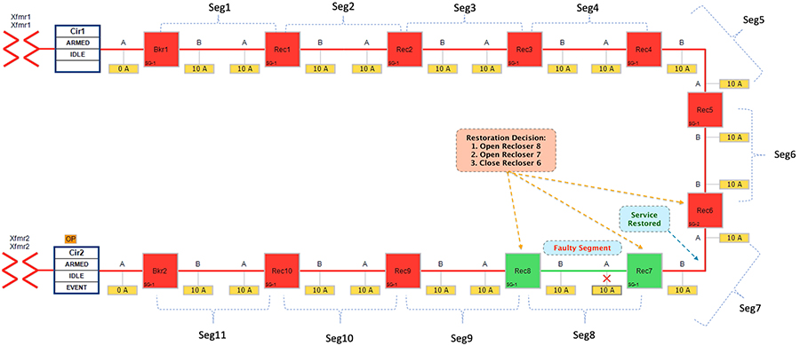
Figure 27 Rural Topology - Fault with Lockout - Restored State
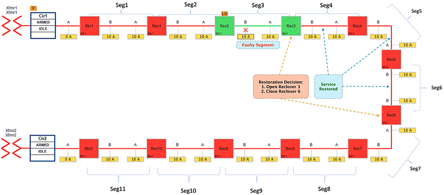
The FLISR SEL DA controller decides:
1.![]() To change the state of Recloser 3 (located between segment 3 & 4) from normally closed state to Open state.
To change the state of Recloser 3 (located between segment 3 & 4) from normally closed state to Open state.
2.![]() To change the state of Recloser 6 (located between segment 6 & 7) from Normally Open state to Closed state. This would result in energizing segments (4-6) with power source from transformer2 feeder.
To change the state of Recloser 6 (located between segment 6 & 7) from Normally Open state to Closed state. This would result in energizing segments (4-6) with power source from transformer2 feeder.
■![]() Customers in non-faulty region in segments 4-6 would have power service restored with the help of FLISR.
Customers in non-faulty region in segments 4-6 would have power service restored with the help of FLISR.
■![]() Due to Fault isolation, power outage is restricted to Customers in the faulty region in segment 3.
Due to Fault isolation, power outage is restricted to Customers in the faulty region in segment 3.
■![]() Fault Location Identification - identified in segment3.
Fault Location Identification - identified in segment3.
■![]() Service Restoration – Restoring the power to non-faulty segment (segment 4-6).
Service Restoration – Restoring the power to non-faulty segment (segment 4-6).
■![]() Isolation - Fault has been restricted to affected customers in segment 3 alone.
Isolation - Fault has been restricted to affected customers in segment 3 alone.
SEL FLISR Rural Topology - FLISR Fault scenario – Open Phase
Open Phase fault applies to three phase circuits, where one of the line voltage is lost. One cause could be due to a bad or loose street pole line jumper that interrupts the line. The loss of voltage will again trigger a DNP3/IP unsolicited message to the DA Controller. DA controller then initiates the necessary action, similar to FLISR Fault scenario - Fault with Lockout.
Figure 28 FLISR Rural Topology – Open Phase - Normal State
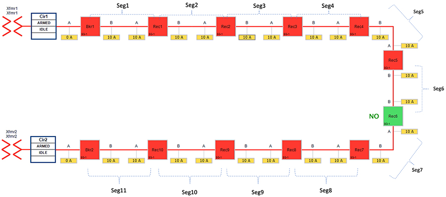
Figure 28 portrays the normal state of the FLISR Rural topology. The emphasis is placed on segment 8 and segment 7. Reclosers corresponding to these segments are Recloser 6,7 and 8.
In above Figure 28:
■![]() Recloser 6 is in Normally Open state. Every other device is in closed state (means, line is energized).
Recloser 6 is in Normally Open state. Every other device is in closed state (means, line is energized).
■![]() Segments 1-6 are powered by feeder from transformer1
Segments 1-6 are powered by feeder from transformer1
■![]() Segments 7-11 are powered by feeder from transformer2
Segments 7-11 are powered by feeder from transformer2
The Open Phase Fault occurs in point A of recloser 7, as highlighted in below figure XX, with a red “X”.
Figure 29 FLISR Rural Topology – Open Phase - Fault State
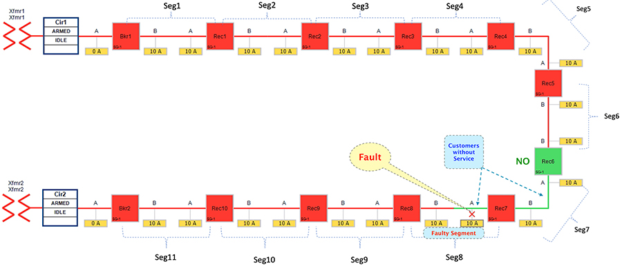
Figure 29 portrays the fault state of the FLISR Rural topology, when fault occurred on segment 8.
This would result in loss of power to below segments:
■![]() Segment 8 (between Recloser 8 and 7) - where the fault did occur
Segment 8 (between Recloser 8 and 7) - where the fault did occur
■![]() Segment 7 (between Recloser 7 and 6) - where the fault did not occur.
Segment 7 (between Recloser 7 and 6) - where the fault did not occur.
In this state, customers in the faulty segment (8) is experiencing loss of power. Along with them, customers in non-faulty segment (7) is also experiencing the loss of power. Before the fault occurred, both of these segments (7 & 8) used to receive power from transformer2.
The moment fault occurred on segment 8, the participating reclosers would be sending DNP3/IP unsolicited messages upstream to the SEL FLISR DA Controller located in the control center. The SEL FLISR DA controller then performs Class0123 polling on every related recloser in the FLISR Rural topology, to get a holistic view of the topology before making any restoration decision.
Figure 30 FLISR Rural Topology – Open Phase - Restored State
The FLISR SEL DA controller decides:
1.![]() To change the state of the Recloser 8 (located between segment 9 & 8) from Closed state to Open state
To change the state of the Recloser 8 (located between segment 9 & 8) from Closed state to Open state
2.![]() To change the state of the Recloser 7 (located between segment 8 & 7) from Closed state to Open state
To change the state of the Recloser 7 (located between segment 8 & 7) from Closed state to Open state
3.![]() To change the state of Recloser 6 (located between segment 6 & 7) from Normally Open state to Closed state. This would result in energizing segment (7) with power source from transformer1 feeder.
To change the state of Recloser 6 (located between segment 6 & 7) from Normally Open state to Closed state. This would result in energizing segment (7) with power source from transformer1 feeder.
■![]() Customers in non-faulty region in segments 7 would have power service restored with the help of FLISR.
Customers in non-faulty region in segments 7 would have power service restored with the help of FLISR.
■![]() Due to Fault isolation, power outage is restricted to Customers in the faulty region (segment 8).
Due to Fault isolation, power outage is restricted to Customers in the faulty region (segment 8).
■![]() Fault Location Identification - identified in segment8.
Fault Location Identification - identified in segment8.
■![]() Service Restoration – Restoring the power to non-faulty segment (segment 7).
Service Restoration – Restoring the power to non-faulty segment (segment 7).
■![]() Isolation - Fault has been restricted to affected customers in segment 8 alone.
Isolation - Fault has been restricted to affected customers in segment 8 alone.
SEL FLISR Rural Topology - FLISR Fault scenario – Loss of Source:
Loss of source applies to fault that occur within the substation yard. For example, a transformer going bad (or) bus fault in the substation, that causes an outage for the entire feeder originating from that substation. In this scenario, the relay within the substation will notify the SEL DA controller of the loss of power which will then initiate the restoration process.
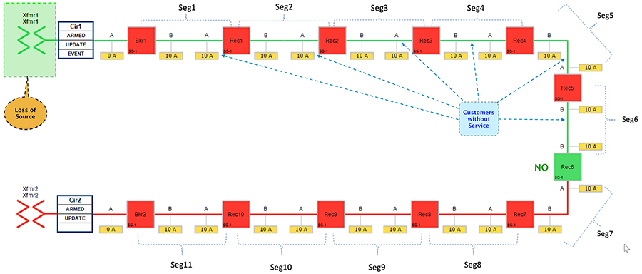
Figure 31 Rural Topology – Loss of Source - Normal State

Figure 31 portrays the normal state of the FLISR Rural topology. The emphasis is placed on entire feeder line from transformer 1 (which include segments 1-6) In normal operational state,
■![]() Recloser 6 is in Normally Open state. All other devices Circuit Breakers & Reclosers are in Closed state.
Recloser 6 is in Normally Open state. All other devices Circuit Breakers & Reclosers are in Closed state.
■![]() Segments 1-6 deriving power from transformer1
Segments 1-6 deriving power from transformer1
■![]() Segments 7-11 deriving power from transformer2
Segments 7-11 deriving power from transformer2
The first feeder transformer was taken out of service to simulate a loss of source. Once the transformer1 is taken out of service, all the downstream customers in segments (1-6) would experience loss of power.
Figure 32 Rural Topology – Loss of Source - Fault State
■![]() Segments 1-6 would experience loss of power, as transformer1 is out of service.
Segments 1-6 would experience loss of power, as transformer1 is out of service.
■![]() Reclosers 6 is still in Normally Open state.
Reclosers 6 is still in Normally Open state.
The circuit breaker and recloser devices sends DNP3/IP unsolicited message upstream to the SEL FLISR DA controller device located in the control center, about the loss of power in the feeder line. The SEL DA controller performs DNP3/IP Class0123 polling from all the related reclosers in the FLISR Rural topology to get a holistic view of the current state of the topology.
The SEL FLISR DA Controller finds the most optimal way to restore the services and, in this case, it chooses to:
■![]() Change the Circuit breaker 1 from Closed state to Open state.
Change the Circuit breaker 1 from Closed state to Open state.
■![]() Change the Recloser6 state from Normal Open state to Close state, provided the additional load will not cause an overload on transformer2.
Change the Recloser6 state from Normal Open state to Close state, provided the additional load will not cause an overload on transformer2.
■![]() This would result in energizing segments (1-6) with power source from transformer2 feeder.
This would result in energizing segments (1-6) with power source from transformer2 feeder.
Figure 33 Rural Topology – Loss of Source - Restored State
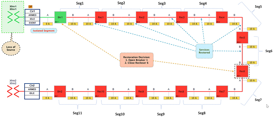
■![]() Customers in all the affected segments (1-6) would have power service restored with the help of FLISR.
Customers in all the affected segments (1-6) would have power service restored with the help of FLISR.
■![]() Due to Fault isolation, transformer1 is isolated by opening Circuit Breaker1. Affected segments are now served by transformer2.
Due to Fault isolation, transformer1 is isolated by opening Circuit Breaker1. Affected segments are now served by transformer2.
■![]() Fault Location Identification - identified in transformer1.
Fault Location Identification - identified in transformer1.
■![]() Service Restoration – Restored the power to affected segments using alternate power source (transformer2).
Service Restoration – Restored the power to affected segments using alternate power source (transformer2).
■![]() Isolation - Fault has been restricted between transformer1 and breaker1.
Isolation - Fault has been restricted between transformer1 and breaker1.
Cisco Resilient (CR) Mesh - Design Considerations for Centralized FLISR use case
This section covers common design considerations, followed by capacity planning of the CR mesh for deployment of Fault Location Isolation and Service Restoration (FLISR) use case. It would also discuss on the number of Distribution Automation (DA) gateways that could be positioned in the CR mesh for the FLISR use case, along with few mesh topology combinations.
It becomes vital to dissect and understand the Application requirement and its exhibited traffic characteristics, to then figure out if CR mesh could cater to it. The first step is to understand the traffic profile of the Application that is being considered for deployment on CR mesh. Listed below are a few issues:
■![]() Understanding the packet profile of the application traffic, for example, FLISR application traffic profile.
Understanding the packet profile of the application traffic, for example, FLISR application traffic profile.
■![]() What subset of the packet profile are periodic? These would be exchanged even without any FLISR event.
What subset of the packet profile are periodic? These would be exchanged even without any FLISR event.
■![]() What subset of the packet profile are event driven that would be exchanged only when there is a FLISR event – for example, only when there is a fault in the feeder, unsolicited report would be generated, followed by FLISR restoration phase?
What subset of the packet profile are event driven that would be exchanged only when there is a FLISR event – for example, only when there is a fault in the feeder, unsolicited report would be generated, followed by FLISR restoration phase?
■![]() What is the latency requirement of the application? For example, 100 ms vs 1 second vs 5 minutes.
What is the latency requirement of the application? For example, 100 ms vs 1 second vs 5 minutes.
–![]() Is it a time critical application or noncritical application?
Is it a time critical application or noncritical application?
■![]() How many numbers of devices participated in the FLISR traffic profile that is under analysis?
How many numbers of devices participated in the FLISR traffic profile that is under analysis?
■![]() What is the accepted max duration for the completion of FLISR use case -- 2 minutes or 5 minutes or other?
What is the accepted max duration for the completion of FLISR use case -- 2 minutes or 5 minutes or other?
■![]() Impact of DA FLISR algorithm on the CR mesh. For example, When the FLISR event fault occurs, does FLISR DA controller have to interact with all the nodes in the CR mesh or does it interact with only subset of the nodes in the CR mesh? This would have an impact on the number of nodes (IR510) competing for the mesh capacity.
Impact of DA FLISR algorithm on the CR mesh. For example, When the FLISR event fault occurs, does FLISR DA controller have to interact with all the nodes in the CR mesh or does it interact with only subset of the nodes in the CR mesh? This would have an impact on the number of nodes (IR510) competing for the mesh capacity.
Addition factors to consider are:
■![]() Number of packets of varying size that is being transmitted (very small, small, medium, large packet sizes)
Number of packets of varying size that is being transmitted (very small, small, medium, large packet sizes)
■![]() Classification of the packets being transmitted (some may be periodic, some are event-driven).
Classification of the packets being transmitted (some may be periodic, some are event-driven).
■![]() Frequency of packets being transmitted (Is it bandwidth intensive?).
Frequency of packets being transmitted (Is it bandwidth intensive?).
■![]() Area and the distance that needs to be aggregated (Urban vs Rural) by the CGR and CR mesh.
Area and the distance that needs to be aggregated (Urban vs Rural) by the CGR and CR mesh.
■![]() Transport layer used for Application traffic (Choice of UDP vs TCP), with recommendation being UDP.
Transport layer used for Application traffic (Choice of UDP vs TCP), with recommendation being UDP.
■![]() DNP3 security if used, would increase the payload size.
DNP3 security if used, would increase the payload size.
■![]() Average number of FLISR events per day.
Average number of FLISR events per day.
Evaluating Number of DA devices in mesh for given FLISR Application in single PAN – A Methodology
Figure 34 Methodology for evaluating number of DA devices in mesh for FLISR Application
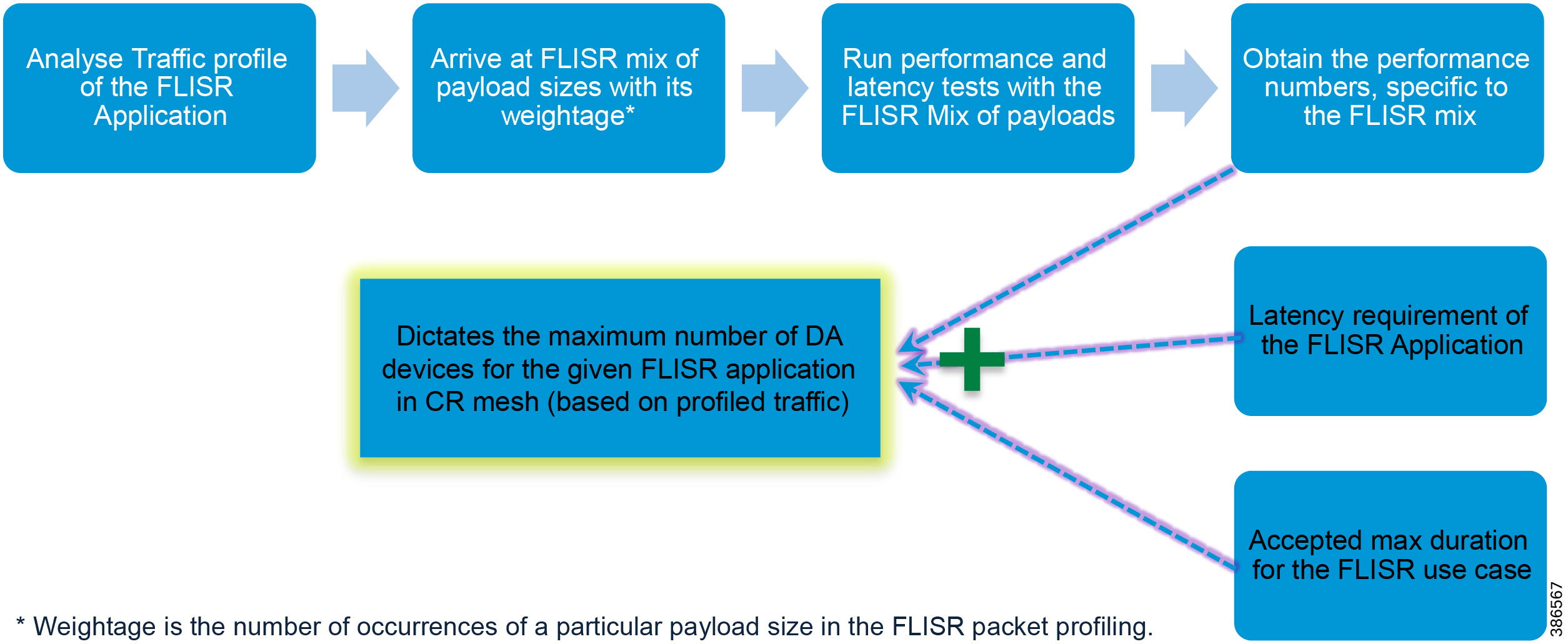
Can a given FLISR application be run over CR mesh? The answer to that question lies in understanding the characteristics of the given FLISR application in terms of payload sizes exchanged, and their respective weightage. Weightage in this case is the number of occurrences of a particular payload size in FLISR packet profiling. Based on the understanding of the FLISR application traffic profile, FLISR mix of payload sizes could be formed. It is then recommended to run performance and latency tests for the FLISR mix of payload sizes, across various Ranks.
Obtained throughput and latency could then be evaluated to check if it could satisfy the FLISR application bandwidth and latency requirement. Combining this observation, along with the maximum accepted duration for the completion of FLISR application use case, the possible number of DA devices that could be supported in the CR mesh could possibly be derived.
Table 3 FLISR Mix of Payload sizes for 10 participating devices – A sample
Note: 372 Datagrams in above table corresponds to Application goodput in sample FLISR use case. All the discussion below revolves around goodput to derive the number of traffic generating DA (utility) devices in the CR mesh.
Common Design Considerations
This section covers the common design considerations, various stages involved in it, and different types of traffic that consumes/competes for the available mesh capacity.
Figure 35 CR Mesh Design Considerations
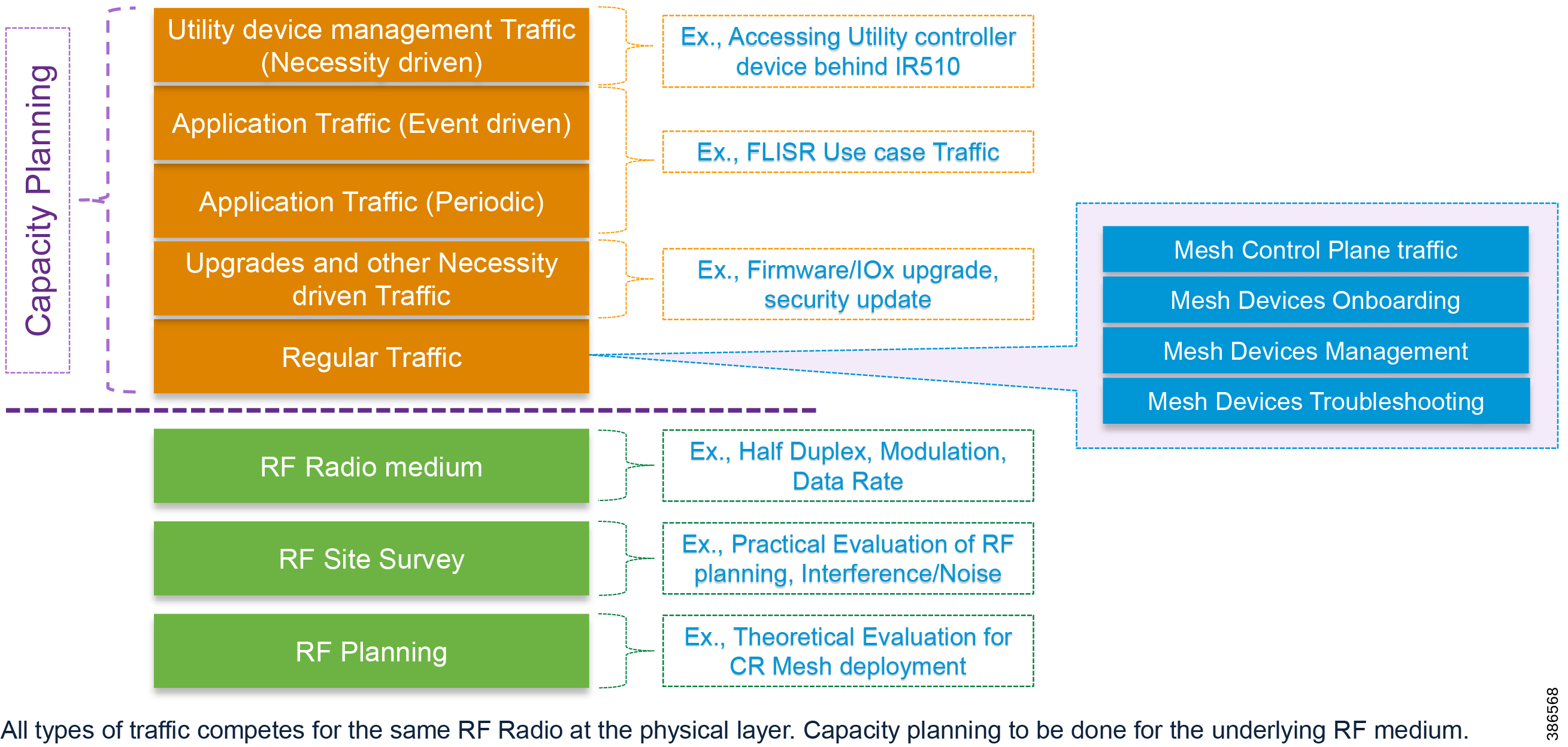
RF Planning
Before actual RF mesh deployment, theoretical planning of the RF site needs to be evaluated with the help of RF planning tools like ATDI. Details like radio and antenna parameters are entered into the RF planning tool. Locations for IR510, IR530 and CGR also needs to be fed into the tool.
The objective of this RF planning exercise is to predict the received signal strength of any given RF link.
RF Site Survey
With the idea derived from the RF planning tool, the theoretical data must be verified with the help of live field tests. In this phase, the CR mesh devices like IR510, IR530 and CGR would be deployed in the planned locations, along with antennas mounted in desired height. Check the received and forward signal strength of any given RF link. Ensure, the RSSI values measured during this RF site survey phase for any particular RF device to be in the expected range, as planned during the RF planning phase.
In this phase, presence of any interference would also be considered. Interferences could be temporary or permanent interference. Also, the noise floor be evaluated with the help of spectrum analyzer.
Note: If the in-band interference is affecting the performance numbers of the node, you may consider improving the quality of the links by adding a range extender. To main stronger signal strength, consider RSSI range greater than or equal to -80 dBm.
For out of band interference, consider using bandpass filter.
Interference could be of transient nature or of permanent nature.
■![]() Transient interference conditions could be due to weather changes like RF foliage, obstacles in front of the antennas, or metallic objects in the way that change after a short time. In these instances, the mesh would self-heal and would retry transmission across all channels. When the conditions improve the performance returns to normal. The retry mechanism would resolve the issues as conditions improve.
Transient interference conditions could be due to weather changes like RF foliage, obstacles in front of the antennas, or metallic objects in the way that change after a short time. In these instances, the mesh would self-heal and would retry transmission across all channels. When the conditions improve the performance returns to normal. The retry mechanism would resolve the issues as conditions improve.
■![]() Permanent interference: As part of RF site survey, if the mean reading indicates that certain sections of the ISM band is excessively used, then operator may consider notching the selective channels.
Permanent interference: As part of RF site survey, if the mean reading indicates that certain sections of the ISM band is excessively used, then operator may consider notching the selective channels.
Note: CR Mesh performance would be proportional to the number of channels being used.
RF Radio medium
RF radio is a half-duplex medium. The radio could either transmit or receive at any point in time. The IR510, IR530 and CGR could support OFDM, 2FSK modulations. In OFDM, 5 data rates are supported (1200, 800, 400, 200 and 50 Kbps). Each of these modulations have a different data rate and RSSI budget. For more details of the data rate supported, please refer to the R510 datasheet.
Data Rate vs Packet Rate vs Goodput
Theoretical maximum throughput for MAC/PHY technologies are expressed in Kbps, Mbps. Meanwhile, one measurement metric is packet rate, which signifies the number of packets that could be transmitted in any given second. Packet rate would vary according to the packet size under consideration. For example, comparing individual packet sizes of 64 vs 512, packet rate for 64 would be more than packet rate of 512. For a range of packet sizes, a packet mix could be composed, and the maximum packet rate could be obtained for the chosen packet mix.
Figure 36 Max Data Rate vs Packet rate vs Goodput
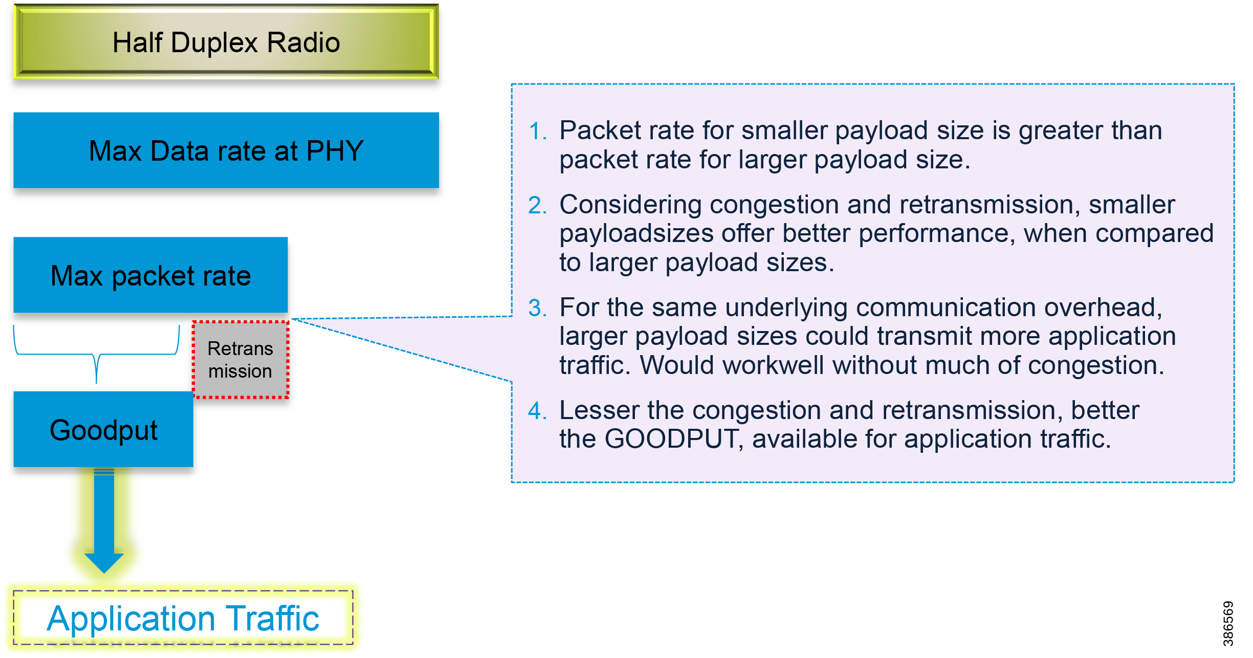
Maximum data rate represents the physical rate of the modulation/PHY Technology chosen (for example, OFDM 800). For a chosen modulation and maximum data rate, and for the chosen packet size (or mix of packet sizes), (packet rate) number of packets could be transmitted. Of these packet rate, some packets could get dropped due to congestion, and may have to be retransmitted. Since the retransmission also has to use the same physical capacity, net effective capacity that is available for application traffic, discounting the retransmission and lower layer communication overheads could be referred as Goodput, in our context.
The key behind extracting the maximum performance out of the CR mesh lies in designing the network, by minimizing the retransmission, and by reducing the possibilities of congestion. It is also vital to clearly understand the characteristics of the application traffic that the mesh needs to carry and consider it while designing the network.
Note: One important recommendation is to plan the CR mesh for 40-50% utilization of its full capacity, leaving the rest for peak traffic, and with some room for future growth.
It is not good practice to plan the CR mesh for 90-100% utilization of its capacity, which is inviting for instability considering the physical nature of the congestion and retransmission in half duplex medium.
Also, UDP as a layer4 transport protocol would offer better performance when compared to TCP in CR mesh, and hence usage of UDP is highly recommended.
Also, it is recommended to configure RPL (Routing Protocol for Low-Power and Lossy Networks) to operate in storing mode, which would eliminate the source routing requirement for the downstream communication to the lower rank devices. This reduces the “source routing header” overhead which in turn could improve the mesh performance. Storing mode when enabled, has an additional benefit to allow peer to peer traffic inside the PAN.
It is highly recommended to mark any latency sensitive critical traffic with dscp value of 18 (AF21), and the next level of moderately critical traffic with dscp value of 10 (AF11). Every other traffic could either be marked with dscp value of 0 or could be left unmarked. Ideal way is to have the QoS dscp values of the packet marked by the Utility controller devices located in the field, as well as by the devices located in the control center. For more details, please refer to the Quality of Service section.
CR Mesh Capacity Planning
Following are some of the different types of traffic that consumes/competes for the available mesh capacity.
■![]() CR Mesh control plane traffic (RPL routing, keepalives, multicast control plane, and so on).
CR Mesh control plane traffic (RPL routing, keepalives, multicast control plane, and so on).
■![]() CR Mesh devices (IR510, IR530) onboarding traffic (IEEE 802.1x, IEEE 802.11i, DHCPv6, and so on).
CR Mesh devices (IR510, IR530) onboarding traffic (IEEE 802.1x, IEEE 802.11i, DHCPv6, and so on).
■![]() CR Mesh devices management traffic (CoAP, CSMP, and so on).
CR Mesh devices management traffic (CoAP, CSMP, and so on).
■![]() CR Mesh devices troubleshooting traffic (ping, traceroute, and so on).
CR Mesh devices troubleshooting traffic (ping, traceroute, and so on).
■![]() CR Mesh devices Upgrade and other necessity driven traffic (Firmware upgrade, IOx upgrade, security update, and so on).
CR Mesh devices Upgrade and other necessity driven traffic (Firmware upgrade, IOx upgrade, security update, and so on).
■![]() Application traffic – periodic (Example, periodic DNP3 Class123 polling every 5 minutes)
Application traffic – periodic (Example, periodic DNP3 Class123 polling every 5 minutes)
■![]() Application traffic – event driven (Example, power outage, fault identification, and successive poll/control traffic).
Application traffic – event driven (Example, power outage, fault identification, and successive poll/control traffic).
■![]() Different types of protocols used for Application communication – (Example, DNP3, MODBUS, IEC 60870, DLMS/COSEM, and so on.)
Different types of protocols used for Application communication – (Example, DNP3, MODBUS, IEC 60870, DLMS/COSEM, and so on.)
■![]() Utility device management traffic (Example, Accessing Utility controller device behind IR510)
Utility device management traffic (Example, Accessing Utility controller device behind IR510)
Figure 37 Mesh Capacity Planning
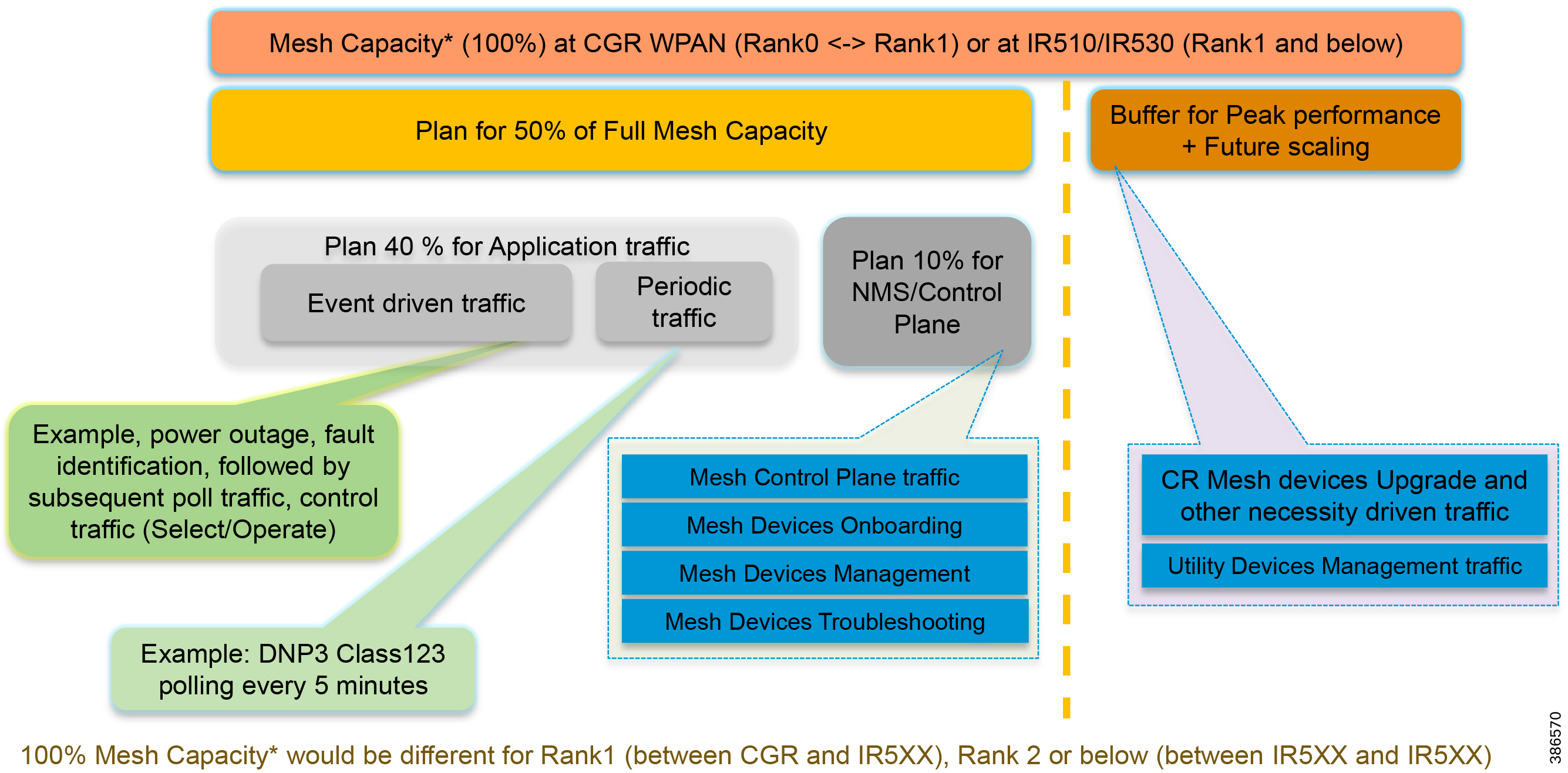
Figure 37 captures a sample mesh capacity allocation for different types of traffic that competes for bandwidth.
Considering the mesh capacity available between CGR and all Rank1 IR510/IR530 as 100%, plan 50% of it for the NMS and application use cases. Leave the remaining 50% as buffer for upgrades and other necessity driven traffic, and for future scaling of number of mesh devices. Of the planned 50% of mesh capacity, 10% could be assumed for control plane traffic as well as NMS related operations like (mesh device onboarding, management and troubleshooting). 40% of the mesh capacity could be planned for Application use case, which includes both periodic traffic, as well as event driven traffic.
While the recommendation for planned capacity is 50%, it could be increased up to a maximum of 70% with 30% headroom.
The numbers referenced in the below section is for demonstration purpose only, just to drive home the procedure. The actual performance and latency numbers for the given application needs to be derived, as mentioned in the sub section Evaluating Number of DA devices in mesh for given FLISR Application in single PAN – A Methodology.
While planning for the worst case and considering the weakest, obtained result could be better than expected.
The Goodput obtained during the performance and latency tests for the given FLISR mix of payload sizes could serve as a good reference for the mesh capacity. For example, if Goodput obtained at Rank1 is 70 datagrams per second for FLISR mix of payload sizes, these 70 datagrams/s could be referred as 100% mesh capacity for all Rank1 nodes. Planning for 40% of the mesh capacity at Rank1 translates to 40% (70) = 28 Datagrams per second (DPS) for entire Rank1.
This 40% capacity (i.e., 28 Datagrams per second) at Rank1 could then be planned for sharing with lower rank nodes. If the FLISR application use case requires 372 datagrams (for 10 devices) to get completed, then 10 devices positioned at Rank1 could take (372/28=) ~14 seconds worth of mesh capacity at 40% loading to complete the FLISR use case. In reality, this could get completed faster, as there might be unused mesh capacity from the remaining 60%. Again, this is a sample number just to demonstrate the procedure.
In case of peer to peer traffic, there could be multiple simultaneous transmissions in the mesh at different hops and channels. This adds extra capacity to the mesh that is not considered in above explanation.
Determining the number of DA devices and mesh depth in the CR mesh for given application:
The depth or the number of hops/ranks in the CR mesh could be dictated by the latency requirement of the use case application.
Note: The next section assumes a few numbers to demonstrate the concept. These numbers do not represent the actual performance or latency numbers of the CR mesh. Run the performance and latency tests to arrive at the actual numbers pertaining to your CR mesh deployment.
Determining the mesh depth
To demonstrate an example, certain assumptions are made and the procedure to determine the mesh depth is shown
■![]() Application requirement: Mesh needs to cater to an application that requires 100ms of one-way latency.
Application requirement: Mesh needs to cater to an application that requires 100ms of one-way latency.
■![]() The latency requirement of 100ms is between CR mesh device (IR510) and control center.
The latency requirement of 100ms is between CR mesh device (IR510) and control center.
■![]() Per-hop latency based on the test results, if found to be in the range of 10-20 ms.
Per-hop latency based on the test results, if found to be in the range of 10-20 ms.
Assuming the worst-case latency of 20ms for one hop, 5 hops might require 100ms of latency. Given such data points, it is recommended to retain the mesh depth to 5 hops or less.
Similarly, if the application is fine with 1 second of one-way latency, theoretically the derivation could be something like (1000ms/20ms=) 50 hops. However, it is recommended not to exceed 8-10 rank depth, especially when the CR mesh is also used for latency sensitive traffic.
Note: Although this section recommends 8-10 rank depth maximum, if the requirement is to reach remote areas with poor connectivity, you could consider increasing the hop depth with range extenders. Choosing to operate at a lower data rate (For example, OFDM 50 Kbps) along with increased hop depth is another option to consider.
Determining the number of DA devices In the CR mesh
As a pre-requisite for this section, performance test must be run for the given application packet profile, as mentioned in the section “Evaluating Number of DA devices in mesh for given FLISR Application – A Methodology”, and obtain the “GOODPUT” measured in Datagrams per second (DPS) for the given Application mix of payload sizes (example, FLISR payload mix).
This section considers only 40% of mesh GOODPUT for the given application at any rank(hop), as per the recommended design. In other words, the intended application load could go up to a max of 40% of mesh capacity plus retransmissions. Meanwhile, at any given second, the then remaining and unused capacity would also be available for application to use, for even better performance.
Note: Data in below table considers the GOODPUT between mesh nodes and control center, without considering the extra capacity obtained when running peer-to-peer traffic.
To obtain the below table output, Bidirectional Multiple flow iperf3 tests needs to be executed with condensed version of multiple payload sizes and its respective weightage as referred in Table 3.
Table 4 Mesh Capacity planning – GOODPUT Allocation table – A sample
The numbers shown in the above table are only sample values, chosen for the purpose of driving the methodology used to derive the number of DA devices in the mesh. Actual numbers could vary depending on the chosen Application packet profiling, and its corresponding performance and latency numbers over the CR mesh.
Data in above Table 4 assumes OFDM modulation with data rate of 800 Kbps. The numbers would vary according to the chosen modulation and data rate.
The 100% Capacity assumed in the above table refers to the multiple node throughput at the same rank. For example, 70 DPS in above table refers to cumulative throughput of multiple nodes in Rank1. If only one node is present in Rank1, 100% capacity could be 2X times approximately (for example,2 x 70 DPS = 140 DPS). Only multiple node throughput has been considered throughout the calculation.
The data in above table is for data originating devices only (devices generating utility goodput traffic). Inclusion of range extenders anywhere in the path doesn’t affect the calculation of number of DA devices.
For example, in case of three rank hierarchy (Rank1-3), if the rank3 device does not have good communication link with rank2 device, inclusion of range extender between rank2 and rank3 device would still be fine, as range extenders only relays the existing traffic, and doesn’t introduce any new data traffic. Hence, a mesh hierarchy with 3 IR510 and one IR530 should be considered as Rank 1-3 with respect to above Goodput allocation table.
Similarly, a mesh hierarchy with 5 IR510 and 2 IR530 could be considered under Rank1-5 category with respect to above goodput allocation table.
Data points required to derive the number of DA devices, for given application use case:
■![]() Goodput DPS for all devices in Rank1. (Example, if 8 nodes are in Rank1, obtain cumulative DPS for all 8 nodes). This corresponds to number 28 in above table.
Goodput DPS for all devices in Rank1. (Example, if 8 nodes are in Rank1, obtain cumulative DPS for all 8 nodes). This corresponds to number 28 in above table.
■![]() Goodput DPS for 3 node hierarchy under any Rank1. This corresponds to number 14 in above table for Rank1-3 hierarchy.
Goodput DPS for 3 node hierarchy under any Rank1. This corresponds to number 14 in above table for Rank1-3 hierarchy.
■![]() Goodput DPS for 5 node hierarchy under any Rank1. This corresponds to number 9.4 in above table for Rank1-5 hierarchy.
Goodput DPS for 5 node hierarchy under any Rank1. This corresponds to number 9.4 in above table for Rank1-5 hierarchy.
■![]() Goodput DPS for 10 node hierarchy under any Rank1. This corresponds to number 6.8 in above table for Rank1-10 hierarchy.
Goodput DPS for 10 node hierarchy under any Rank1. This corresponds to number 6.8 in above table for Rank1-10 hierarchy.
Data point taken based on FLISR Application packet profiling for 10 devices:
■![]() Total number of datagrams required for one FLISR application use case to complete (with 10 devices) = 372 datagrams.
Total number of datagrams required for one FLISR application use case to complete (with 10 devices) = 372 datagrams.
Below section shall be discussed as multiple cases. The mesh could contain multiple rank1 devices. The term “10 nodes per rank1 hierarchy”, refers to linear mesh of 9 CR mesh devices, under one CR mesh rank1 device (IR510/IR530). Similarly, the term “3 nodes per rank1 hierarchy” would refer to linear mesh of 2 CR mesh devices under one rank1 device.
The application use case considered for below case study is FLISR, and it took 372 datagrams for FLISR to complete for a total of 10 participating devices. This would be used as reference for completion of FLISR use case/10 nodes, in the below cases.
Table 5 Number of DA devices in mesh – summary table
Table 5 captures the summary of recommendations given for different scenarios. For more details, refer to below sections.
Figure 38 Number of DA devices in CR mesh – Two Phases
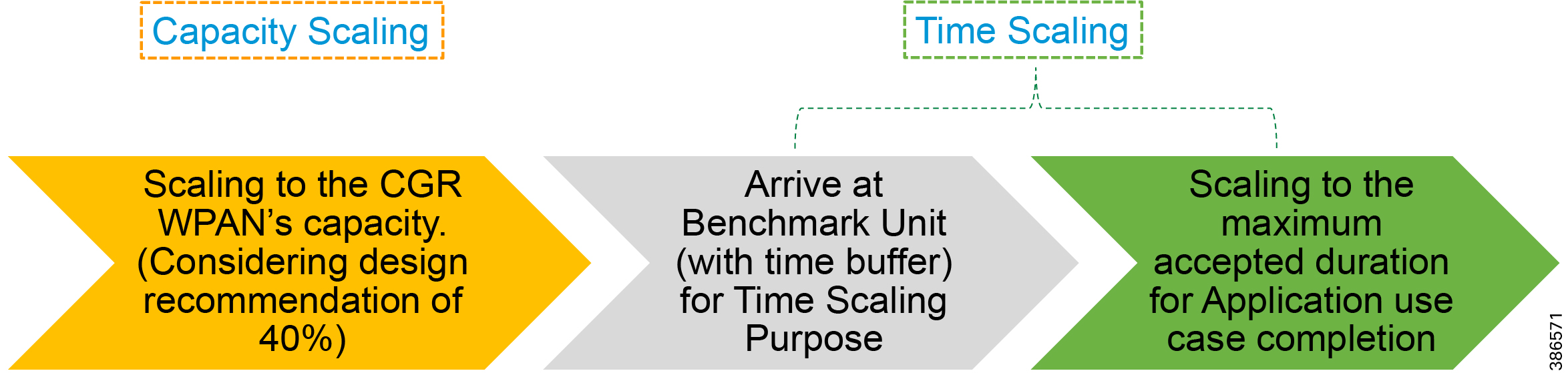
■![]() Number of devices derived based on CGR WPAN goodput rate. This is scaling to fit within WPAN capacity at any given second. Example: 7 devices with goodput rate of 4 datagrams per second (DPS) is catered by WPAN which has goodput rate of 28 DPS. Therefore, 7 devices could be allowed to transmit at any given second.
Number of devices derived based on CGR WPAN goodput rate. This is scaling to fit within WPAN capacity at any given second. Example: 7 devices with goodput rate of 4 datagrams per second (DPS) is catered by WPAN which has goodput rate of 28 DPS. Therefore, 7 devices could be allowed to transmit at any given second.
■![]() Considering some time buffer, arrive at Benchmark unit for further time scaling.
Considering some time buffer, arrive at Benchmark unit for further time scaling.
■![]() Time Scaling: Number of devices derived based on Application acceptable maximum duration limit. This is scaling to fit the number of DA devices over period of time. For example, if total datagrams for use case to complete is 72, 7 devices (each with a goodput rate of 4 DPS), would take (72 / (7*4) =) 3 seconds for use case to complete.
Time Scaling: Number of devices derived based on Application acceptable maximum duration limit. This is scaling to fit the number of DA devices over period of time. For example, if total datagrams for use case to complete is 72, 7 devices (each with a goodput rate of 4 DPS), would take (72 / (7*4) =) 3 seconds for use case to complete.
–![]() Assuming 3X time buffer, consider 12 seconds instead of 3 seconds for one use case.
Assuming 3X time buffer, consider 12 seconds instead of 3 seconds for one use case.
–![]() Time taken for 1 set of 7 devices = 12 seconds.
Time taken for 1 set of 7 devices = 12 seconds.
–![]() This way, if application accepted maximum duration limit = 120 seconds, then the mesh could cater up to a maximum of 10 sets (120s/12s per set of 7 devices). Theoretically, these 10 sets with 7 devices each could go up to a maximum of 70 devices.
This way, if application accepted maximum duration limit = 120 seconds, then the mesh could cater up to a maximum of 10 sets (120s/12s per set of 7 devices). Theoretically, these 10 sets with 7 devices each could go up to a maximum of 70 devices.
■![]() The resulting capacity scaling count = 7 devices; Time scaling count = 70 devices.
The resulting capacity scaling count = 7 devices; Time scaling count = 70 devices.
■![]() Which means that 70 is the number of DA devices that could be deployed over CR mesh for the given application traffic characteristics.
Which means that 70 is the number of DA devices that could be deployed over CR mesh for the given application traffic characteristics.
Case1: Considering all nodes in Rank1.
This case assumes all the devices are positioned in Rank1 level itself.
With goodput of 28 DPS, 372 datagrams for FLISR application could take (372/28=) 14 seconds. In fact, it could be lesser than 14 seconds considering that application traffic is planned only for 40% of the mesh capacity, and any portion of the remaining 60% could possibly be available, thus having a possibility to offer a performance, better than 14 seconds. However, below calculation considers 14 seconds as per the 40% design recommendation.
The 372 datagrams FLISR packet profiling was based on 10 devices. So, 10 rank1 devices could take approximately 14-15 seconds to complete the FLISR use case.
Table 6 Number of DA devices – All Rank1 nodes - scaling type and considerations
Above table is a theoretical extrapolation. In practical, it is advised to reduce the number of devices that competes for the same transmission medium.
The number of devices that could be positioned in the mesh depends on the accepted maximum duration for FLISR use case. If the FLISR use case accepted maximum duration is 2-3 minutes, consider positioning 30-40 Rank1 nodes. If the FLISR use case accepted maximum duration is 4-5 minutes, consider positioning 45-60 Rank1 nodes.
Case2: Considering up to 10 nodes per rank1 hierarchy
This case assumes the Application latency requirement permits 10 hops of IR510/IR530 to be positioned under any Rank1 device.
■![]() Goodput DPS for Rank1-10 nodes = 6.8.
Goodput DPS for Rank1-10 nodes = 6.8.
■![]() Up to 10 nodes are considered per rank1 hierarchy.
Up to 10 nodes are considered per rank1 hierarchy.
With goodput of 6.8 (~7) DPS, 372 datagrams for FLISR application could take (372/6.8=) 55 seconds.
At the rate of 7 DPS per rank1, and with goodput rate of 28 DPS for all Rank1, (28/7=) 4 Rank1 devices and its 10-node hierarchy should be able to transmit comfortably, without much of retransmission. This translates to 4 rank1 * 10 devices per rank1= 40 devices.
This could be fine, when the accepted duration for FLISR use case to complete is 2 minutes or above (considering 2 x 55 seconds).
Figure 39 Considering up to 10 nodes per rank1 hierarchy
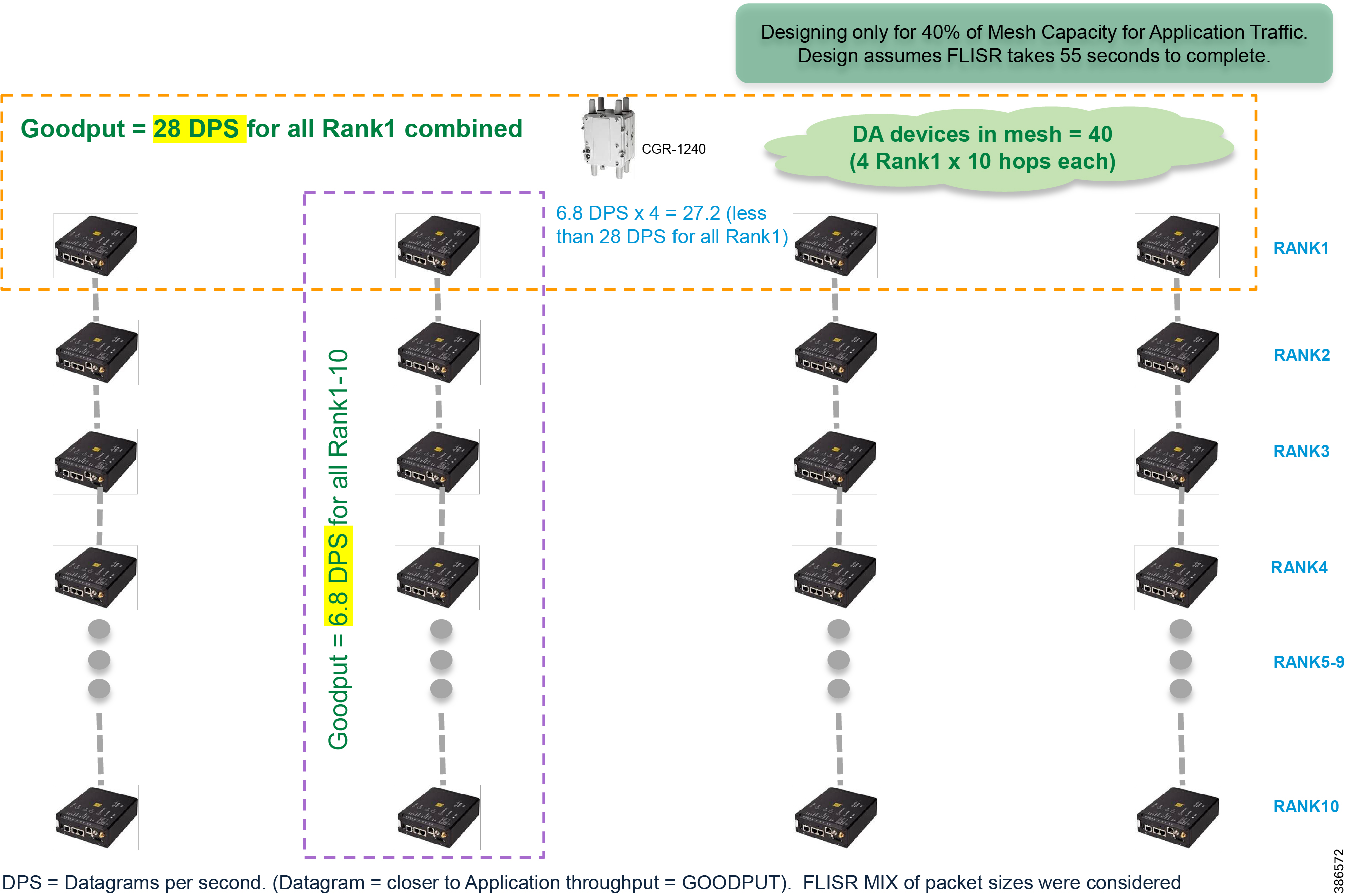
If the accepted maximum duration for FLISR to complete is 4-5 minutes, we could afford to have some congestion and retransmissions at the Rank1. Hence, we could add more branches and increase the number of DA devices positioned under the CR mesh. For example, if 2-3 minutes could serve 4 Rank1 capacity, allowing some buffer for retransmission, 4-5 minutes could serve 5-6 Rank1 devices worth of capacity, each with hierarchy of nodes underneath it.
Table 7 Number of DA devices – up to 10 nodes per rank1 hierarchy - scaling type and considerations
Case3: Considering up to 5 nodes per rank1 hierarchy
This case assumes the Application latency requirement permits 5 hops of IR510/IR530 to be positioned in any Rank1 hierarchy.
■![]() Goodput DPS for Rank1-5 nodes = 9.4
Goodput DPS for Rank1-5 nodes = 9.4
■![]() Up to 5 nodes are considered per rank1.
Up to 5 nodes are considered per rank1.
■![]() Considered FLISR packet profiling has 372 datagrams for 10 devices.
Considered FLISR packet profiling has 372 datagrams for 10 devices.
Figure 40 Considering up to 5 nodes per rank1 hierarchy
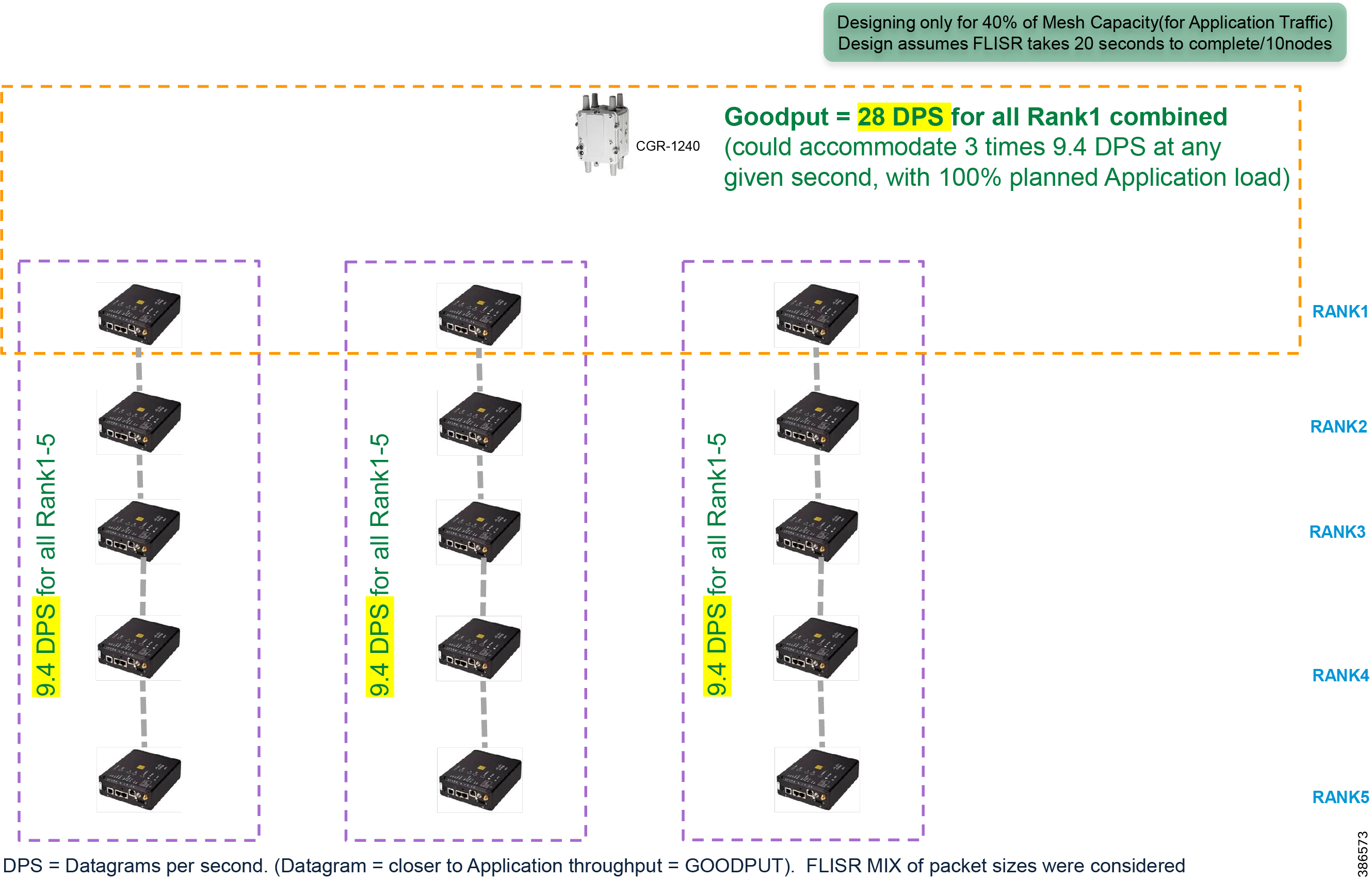
All the calculations below assume only 40% of full capacity, factoring in multiple nodes in same rank. For example, 28 DPS in Rank1 is the cumulative of all rank1 nodes, at 40% capacity.
With goodput of 9.4 DPS per branch of 5 nodes, combined goodput for 10 nodes = 18.8 DPS
Time taken to complete FLISR application/10 nodes = (372/18.8) = 20 seconds.
CGR WPAN (at 40% capacity) could serve FLISR application traffic worth 15 nodes at any point in time. (example, 9.4 DPS * 3 = 28.2 DPS, close enough to 28 DPS offered by Rank1).
In 20 seconds, 15 nodes worth of FLISR application traffic could be served.
This scaling limit comes from the CGR WPAN per second capability (again at 40% planned capacity). In reality, any unused/available mesh capacity of the remaining 60% would contribute to even better performance.
Another level of device scaling could be achieved based on maximum accepted duration for the completion of FLISR use case (for example, it could be 1 minute or 2 minutes or 5 minutes or N minutes). To achieve that, consider some time buffer and arrive at a benchmark unit of measurement. For example, at the rate of 15 nodes/20 seconds, theoretically 45 nodes could be served in 1 minute. However, allowing some time buffer, only 30 nodes are considered for 2 minute interval, and only 15-30 nodes were considered for 1 minute interval.
Table 8 Number of DA devices – up to 5 nodes per rank1 hierarchy - scaling type and considerations
As per above table, the number of devices that could be positioned in the mesh depends on the accepted maximum duration for FLISR use case. If the FLISR use case accepted maximum duration is 2 minutes, consider positioning 30 devices. If the FLISR use case accepted maximum duration is 4-5 minutes, consider positioning 50-60 devices (with 12 Rank1 and with 4 devices under each Rank1 node). The above design considers mesh with sufficient time buffer to deliver a better FLISR performance.
Note: The additional number of mesh devices can be positioned on the mesh, considering the buffer that was accounted in beginning. However, it is recommended to monitor the network for its expected performance, before adding additional number of devices, in incremental stages.
Case4: Considering up to 3 nodes per rank1 hierarchy
This case assumes the Application latency requirement permits 3 hops of IR510/IR530 to be positioned in any Rank1 hierarchy.
■![]() Goodput DPS for Rank1-3 nodes = 14
Goodput DPS for Rank1-3 nodes = 14
■![]() Up to 3 nodes are considered per rank1.
Up to 3 nodes are considered per rank1.
■![]() Considered FLISR packet profiling has 372 datagrams for 10 devices.
Considered FLISR packet profiling has 372 datagrams for 10 devices.
Figure 41 Considering up to 3 nodes per rank1 hierarchy
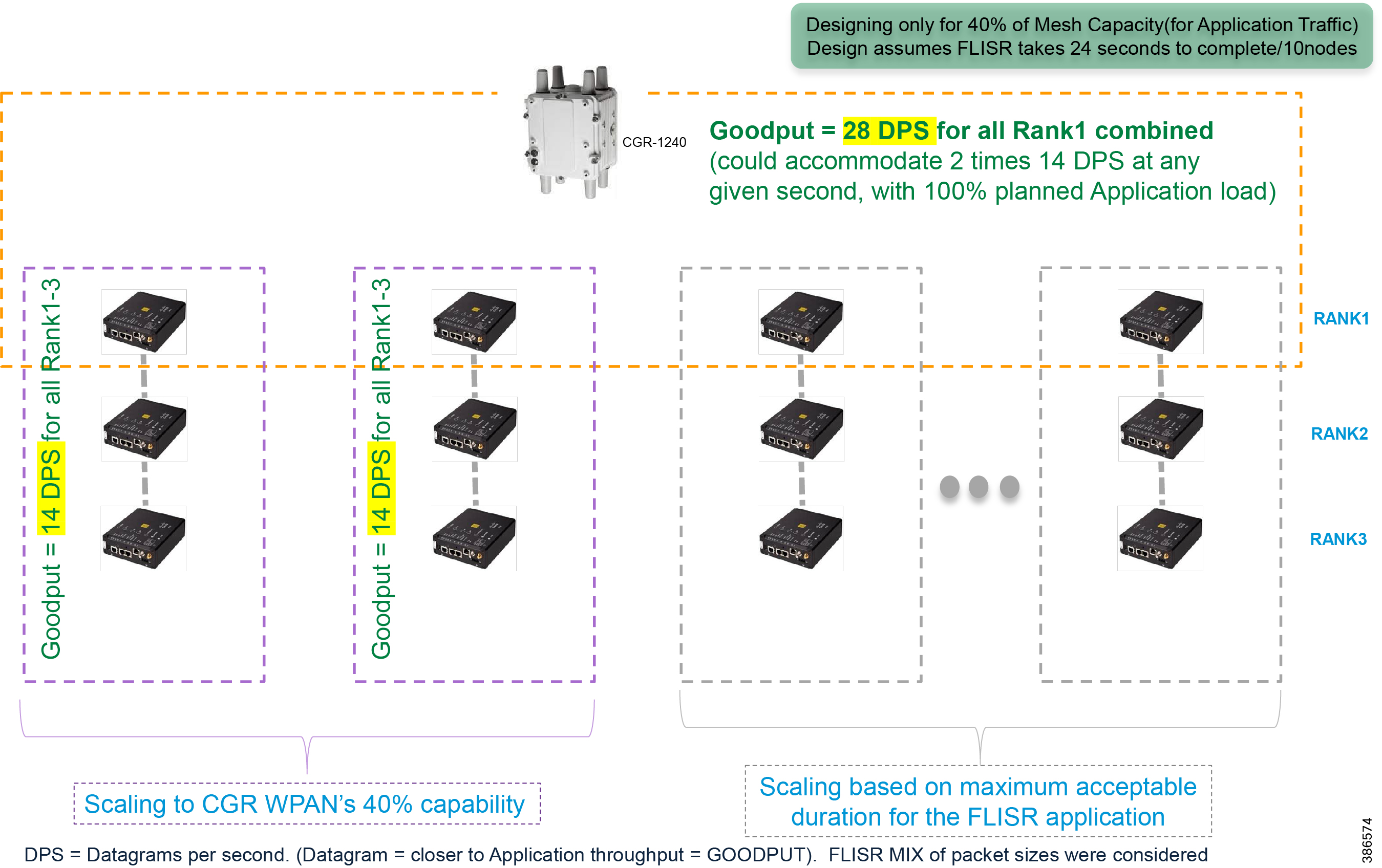
All the calculations below assume only 40% of full capacity, factoring in multiple nodes in same rank. For example, 28 DPS in Rank1 is the cumulative of all rank1 nodes, at 40% capacity.
At the rate of 14 DPS per rank1, and with goodput rate of 28 DPS for all Rank1, (28/14=) 2 Rank1 devices and its 3-node hierarchy should be able to transmit comfortably, at full application planned capacity. This translates to positioning 2 rank1 * 3 devices per rank1= 6 devices without much of congestion and retransmission.
The reference 372 datagrams was profiled for 10 devices. This translates to 224 datagrams for 6 devices.
With goodput of 28 DPS for 6 devices, 224 datagrams for FLISR application could take (224/28=) 8 seconds for 6 devices. In 16-20 seconds, goodput from 12 devices could be served. In 24-30 seconds, goodput from 18-20 devices could be served.
Another level of device scaling could be achieved based on maximum accepted duration for the completion of FLISR use case (for example, it could be 1 minute or 2 minutes or 5 minutes or N minutes). To achieve that, consider some time buffer and arrive at a benchmark unit of measurement. For example, at the rate of 18 nodes/30 seconds, theoretically 72 nodes could be served in 2 minutes. However, allowing some time buffer, only 30 nodes are considered for 2-minute interval., and only 20-30 nodes were considered for 1-minute interval.
Table 9 Number of DA devices – up to 3 nodes per rank1 hierarchy - scaling type and considerations
As per above table, the number of devices that could be positioned in the mesh depends on the accepted maximum duration for FLISR use case. If the FLISR use case accepted maximum duration is 2 minutes, consider positioning 20-30 devices. If the FLISR use case accepted maximum duration is 5 minutes, consider positioning 40-60 devices. Above design attempts to reduce congestion as much as possible and is expected to deliver a better FLISR performance.
Scaling Up – Adding more nodes
CR Mesh should be able to handle scale much more than what was mentioned in above tables. Still, all the planning that has been done so far has been with 40% of the mesh capacity for application goodput communication. Additionally, time buffer has been considered while trying to derive the number of DA devices in the mesh. It is recommended to start with 50% of recommended scale, evaluate the mesh performance, profile the mesh utilization for the applicable use cases, and then take data driven incremental steps to add more nodes.
Note: The more the mesh is designed to reduce congestion and retransmission, better the performance would be.
Given the lossy nature of the radio medium, it is recommended to design for moderate scale and achieve better performance, than to design for high scale and suffer low performance.
Solution Architecture and Components Selection
This chapter, which covers the DA places in network, the solution architecture for various DA application flows. and details about solution components that make up the DA architecture, includes the following major topics:
■![]() FAN Layer Infrastructure Components
FAN Layer Infrastructure Components
■![]() WAN Layer Infrastructure Components
WAN Layer Infrastructure Components
■![]() Headend Layer Infrastructure Components
Headend Layer Infrastructure Components
Places in the Network
This section describes the Smart Grid Multi-Services Field Area Network solution's building blocks for Distribution Automation applications. The Cisco FAN solutions offers end-to-end physical and network security to detect unauthorized access to the Distribution Network's assets and to prevent access to DA communication infrastructure, as well as network services such as QoS and multi-services (DA, AMI, DER and multi-tenant). The solution offers a centralized network management system that simplifies network and device provisioning through automation process called ZTD and an advanced graphical interface for large-scale network visualization and management. In addition, customers can deploy and manage their own or third party applications at the edge in the NAN block, enabling new services and functionality to the existing Distribution grid assets.
Figure 42 Cisco FAN Solution Building Blocks
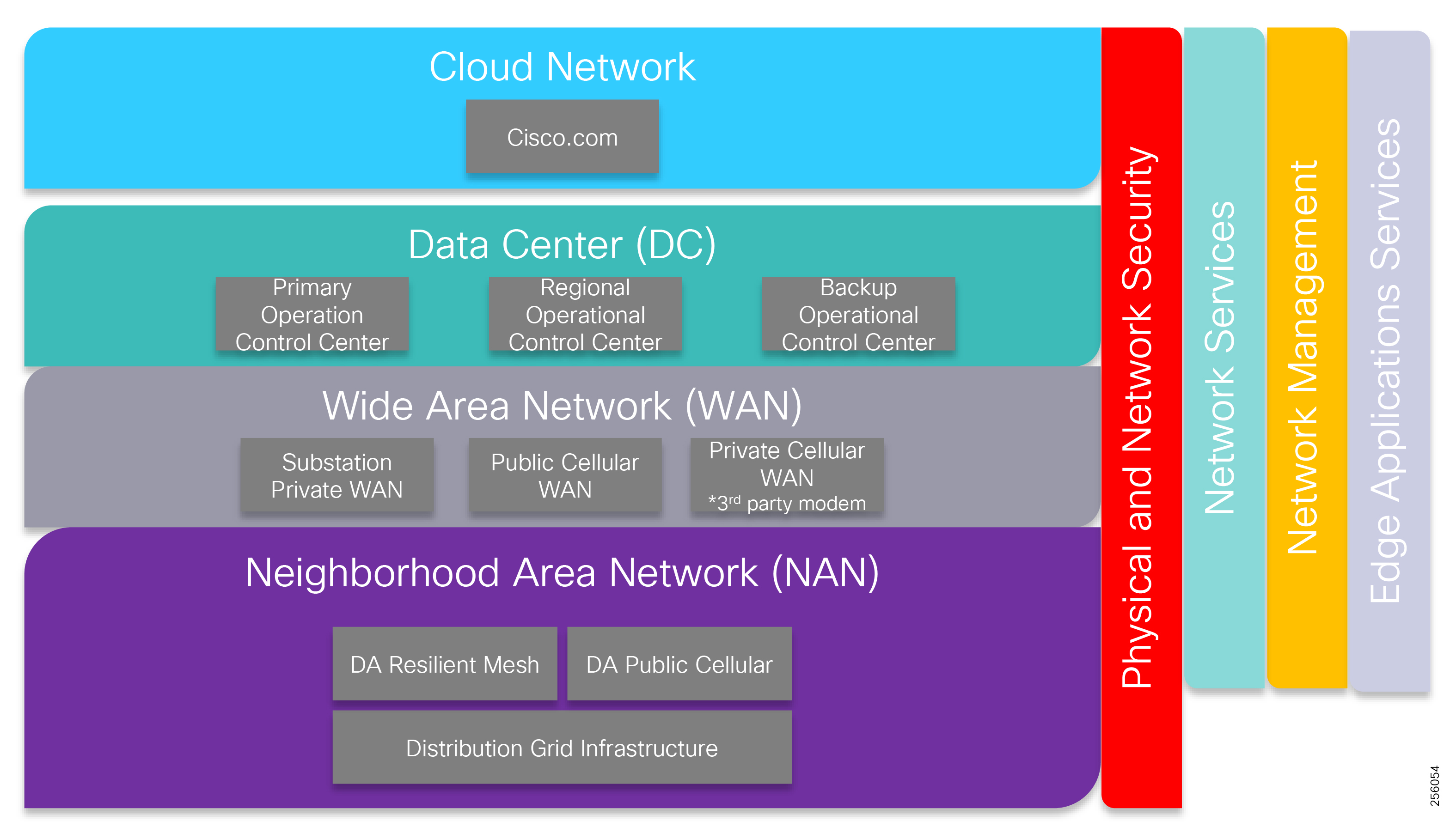
Neighborhood Area Network
The NAN is the last mile of the network communication infrastructure connecting the Utility Distribution Infrastructure assets for DA, AMI, and Remote Workforce management to the rest of the company's communication infrastructures: the Substation WAN and Data Center or Control Centers. The grid equipment, which includes feeder capacitor banks, voltage regulators, reclosers, end-of-line meters, and the transformer meters area, is connected to Cisco FAN Solution DA gateways devices such as IR510, IR800, and IR1100 using serial interfaces RS232 or RS485 or Ethernet for newer grid equipment. Cisco offers two solutions based on standard technologies:
■![]() Cisco Resilient Mesh, which leverages the unlicensed ISM spectrum in the 900 MHz band, IEEE 802.15.4g/e, and 6LoWPAN for customers interested in deploying a private solution that offers low OpEx.
Cisco Resilient Mesh, which leverages the unlicensed ISM spectrum in the 900 MHz band, IEEE 802.15.4g/e, and 6LoWPAN for customers interested in deploying a private solution that offers low OpEx.
■![]() Public Cellular DA, which uses standard public cellular 3G/4G technology and requires a monthly cellular service in order to function.
Public Cellular DA, which uses standard public cellular 3G/4G technology and requires a monthly cellular service in order to function.
Data from the electric grid devices is transported using one of the Cisco FAN solution to different aggregation, which represent exit points out of the NAN block. The aggregation points are referred to as Field Area Routers (FAR), which use the Cisco modular CGR 1000 series router to forward the traffic upstream towards the utility energy management systems. The FAR devices provide an interface to the WAN block that acts as the backhaul for NAN.
This infrastructure, which enables customers to monitor and control the Distribution Network and perform measurement of electricity consumed and produced by prosumers, provides the foundation for advanced applications like Distribution Automation, Distributed Energy Resources (DER), and Demand Response (DR), which is a program for optimizing energy usage during peak periods.
NANs also serve as a foundation for future virtual power plants, which are comprised of distributed power generation stations, residential energy storage (for example, in combination with electric vehicle charging), and small-scale trading communities.
In the AMI scenario, the connected grid endpoints in the NAN are the smart meters that are part of the mesh radio network. These smart meters are IP-enabled grid devices with an embedded IPv6-based communication stack that are powered by the Cisco IPv6 CG-Mesh SDK.
Refer to the Cisco Developer Network (CDN) to learn more about IP-enablement for partner technologies.
Wide Area Network
The WAN tier is responsible for providing the communications overlay between the NAN block through their FARs and Data Center or Cloud Services block. The Cisco FAN solution is agnostic to the customer's WAN infrastructure. This may be:
■![]() Private high speed in the case of the Substation On-Net, which leverages customers' dark fiber infrastructure
Private high speed in the case of the Substation On-Net, which leverages customers' dark fiber infrastructure
■![]() Off-Net, which is based on public services offered by Service Providers like Layer 2 Carrier Ethernet or Layer 3 MPLS service combined with a VPN design to ensure privacy and security
Off-Net, which is based on public services offered by Service Providers like Layer 2 Carrier Ethernet or Layer 3 MPLS service combined with a VPN design to ensure privacy and security
Popular WAN backhaul options are Fiber, Ethernet, and Cellular 3G/4G. Other backhaul types for FARs may be a public or private IEEE 802.11 Wi-Fi smart cities infrastructure, satellite, or Private Cellular (if utilities have purchased cellular spectrum).
The architecture assumes established network connectivity from the NAN to the headend systems. Data security forwarded over the WAN is critically important; incorporating IPSec tunnels in the design helps meet this requirement.
Data Centers
The Data Center block represents all customer Control Center or Energy Operational Center locations that are used to manage the Distribution Network. At a minimum, a customer will have a Primary Control Center and a Back-up Control Center for disaster recovery scenarios. For large utilities, the Data Center block could have a hierarchical layout with an additional layer besides the Primary/Back-up Control Centers. This secondary layer contains the regional Control Centers that only manage a subset of the entire Distribution Network. The EOC hosts all applications necessary to operate, manage, and secure the FAN sites and equipment. It is typically located in the Utility facility and may be co-located with the Utility IT Data Center in some cases. In a multi-service FAN deployment, the EOC will host the applications and associated servers performing the tasks required by DA, AMI, DER, Remote Asset Management, and Remote Workforce Management.
Cloud Network
With the recent trends in the IT industry, customers can leverage new services that are based on Cloud Services offered by different companies. Small utilities that don't desire to maintain a Data Center infrastructure and prefer to subscribe to Cloud Services could implement Cisco Cloud Services like Jasper or Kinetic for the FAN solution.
Application Flows
The communication infrastructure is designed to support the different Energy Systems application flows. In general, the customer energy systems are located in the Data Center or Control Center locations and use a Publish/Subscriber application architecture to monitor and control the Distribution Grid assets in the NAN. The data exchange flows between a Primary station located in the DC and Subordinate stations located in the NAN over the WAN infrastructure. FlexVPN technology makes the solution agnostic to the WAN transport infrastructure and ensures that data is secure at it travels the WAN.
Figure 43 depicts the following main application flow types:
1.![]() Publish-Subscriber between DMS and grid assets
Publish-Subscriber between DMS and grid assets
2.![]() Publish-Subscriber between DMS and Edge Compute Applications and between Edge Compute Applications and grid assets
Publish-Subscriber between DMS and Edge Compute Applications and between Edge Compute Applications and grid assets
3.![]() Publish-Subscriber between DMS and Substation RTU and Substation RTU and grid assets
Publish-Subscriber between DMS and Substation RTU and Substation RTU and grid assets
4.![]() Publish-Subscriber between grid assets using peer-to-peer communication
Publish-Subscriber between grid assets using peer-to-peer communication
Figure 43 Application Traffic Flow Types
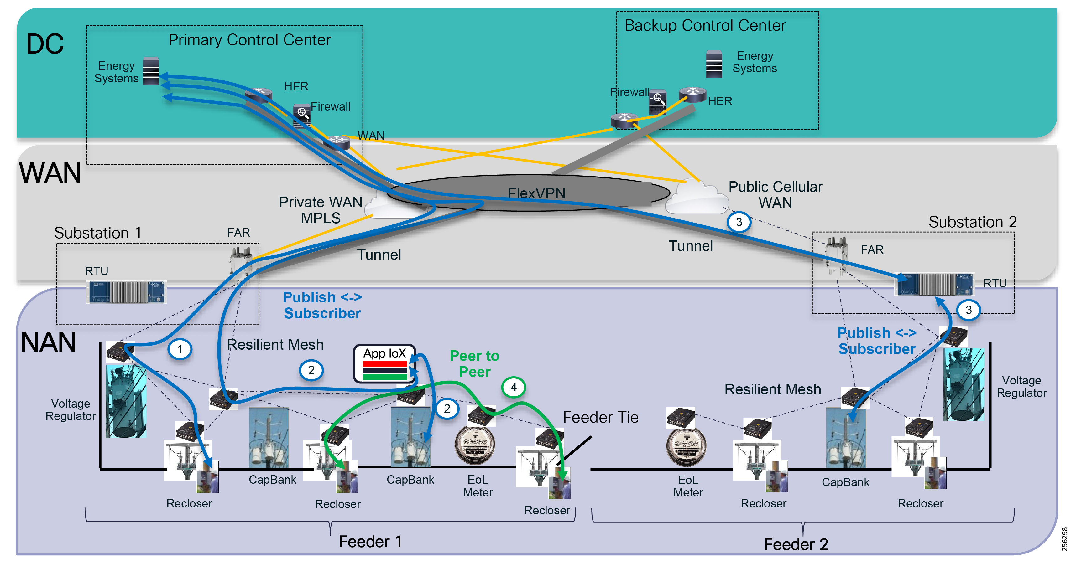
FAN Layer Infrastructure Components
FAN IEEE 802.15.4g/e Devices
The FAN DA solution uses the following products to build a radio mesh network based on the IEEE 802.15.4g/e standard. The radio network requires a radio mesh Personal Area Network (PAN) coordinator. This function is supported by the solution FARs. Cisco offers CGR1240 or CGR1120 that customer can use as FAR devices.
|
|
|
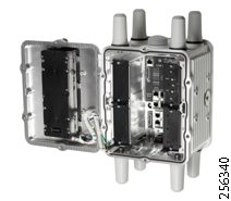
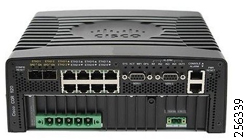
One big difference between the two products is that the CGR1240 is an IP67-rated device that can be deployed outdoors, whereas the CGR 1120 is rated as an IP30 device and is targeted to indoor substation installations. The other main difference is the number of modular slots. The CGR1240 has four module slots that give customers the ability to deploy multiple services or backhaul interfaces; the CGR1120 only has two slots.
Lastly, the CGR 1240 obtains its power by AC while the CGR1120 supports both AC and DC.
|
|
|
|
|
|
|
|
|
|
||
CGR1240 w/ 4 module slots,2 GE,2 serial,4 FE LAN, Wi-Fi, GPS |
CGR 1120 w/ 2 module slots,2 GE,2 serial,6 FE LAN, Wi-Fi, GPS |
Note: This solution design recommends the software 15.7.03 and mesh 6.0.19.
Note: For additional information on CGR1240, refer to the following URL:
■![]() https://www.cisco.com/c/en/us/support/routers/1240-connected-grid-router/model.html
https://www.cisco.com/c/en/us/support/routers/1240-connected-grid-router/model.html
Note: For additional information on CGR1120, refer to the following URL:
■![]() https://www.cisco.com/c/en/us/support/routers/1120-connected-grid-router/model.html
https://www.cisco.com/c/en/us/support/routers/1120-connected-grid-router/model.html
The new Connected Grid Module (CGM) Orthogonal frequency-division multiplexing (OFDM) module supports OFDM modulation and data rates based on the IEEE 802.15.4g Option 2, which is standard for DA FLISR and Volt/VAR applications.
Figure 44 CGM WPAN OFDM Module
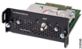
|
|
|
Besides the CGM module, customers can add the Cisco Content Switching Module (CSM) to enable Edge Compute on the aggregation points of the mesh network.
Figure 45 CGM Edge Compute Server Module
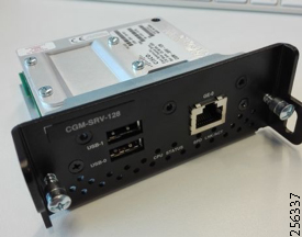
|
|
|
Note: For additional information on CGR CSM Modules, refer to the following URL:
■![]() https://www.cisco.com/c/en/us/support/docs/cloud-systems-management/iox/212038-Configure-CGM-SRV-IOx-Module-on-CGR1xxx.html
https://www.cisco.com/c/en/us/support/docs/cloud-systems-management/iox/212038-Configure-CGM-SRV-IOx-Module-on-CGR1xxx.html
FAR routers can be also configured with 4G modems for backup network services. In case the primary backhaul link fails, the traffic from the field devices can be transported back to the Control Center or over a Public Cellular network using an overlay VPN (FlexVPN) to secure the data over the service provider network.
Figure 46 North America CGR 4G Cellular Modules
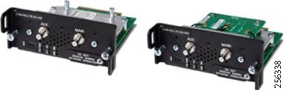
|
|
|
|
|
|
|
FW Switching for MC7354 Multi Carriers North America Verizon |
Note: For additional information on CGR CGM Cellular Modules, refer to the following URL:
■![]() https://www.cisco.com/c/en/us/products/collateral/routers/1000-series-connected-grid-routers/datasheet-c78-730624.html
https://www.cisco.com/c/en/us/products/collateral/routers/1000-series-connected-grid-routers/datasheet-c78-730624.html
The IR510 is the next-generation DA Gateway that connects utility grid assets to the Cisco Resilient Mesh network. It supports higher data rates based on OFDM modulation and is best suited for DA applications. It has dedicated hardware resources for Edge Compute applications, so that customers can deploy their own applications at the edge of the network.
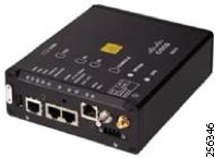
|
|
|
|
|
|
|
|
|
|
|
|
|
|
|
Note: For additional information on IR510, refer to the following URL:
■![]() https://www.cisco.com/c/en/us/products/collateral/routers/500-series-wpan-industrial-routers/datasheet-c78-730550.html
https://www.cisco.com/c/en/us/products/collateral/routers/500-series-wpan-industrial-routers/datasheet-c78-730550.html
When grid assets are not close to each other enough, for example rural area with long feeders, or no clear line of sight exists between nodes, customers can deploy the Cisco Range Extender to provide additional signal coverage. The latest range extender product release is the IR530, which supports the higher OFDM data rates.
Figure 48 IR530 Range Extender
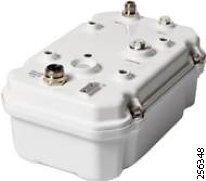
|
|
|
|
|
|
|
|
|
|
|
|
|
|
|
|
|
|
|
|
|
|
|
IR530 with single antenna and battery, 915MHz-WPAN. For North and South America except Brazil. |
|
|
|
|
|
|
|
|
|
|
|
|
|
|
|
Industrial Wireless AP 3702, 4 RF ports on top, B reg domain |
||
Industrial Wireless AP 3702, 4 RF ports on top, A reg domain |
||
Note: For additional information on IR530, refer to the following URL:
■![]() https://www.cisco.com/c/en/us/products/collateral/routers/500-series-wpan-industrial-routers/datasheet-c78-740201.html
https://www.cisco.com/c/en/us/products/collateral/routers/500-series-wpan-industrial-routers/datasheet-c78-740201.html
FAN IEEE 802.11 (Wi-Fi) Devices
Cisco IoT Wi-Fi products can be used for DA use cases that require very low latency and high bandwidth; for example, FLISR with IEC61850 Goose messaging. IoT Wi-Fi products can be used to extend backhaul connectivity for Resilient Mesh FAR devices as highlighted in Figure 54.
|
|
|
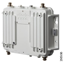
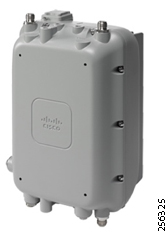
|
|
|
|
|
|
||
|
|
||
|
|
||
|
|
||
|
|
||
|
|
For additional information on IW3702, refer to the following URL:
■![]() https://www.cisco.com/c/en/us/products/collateral/wireless/industrial-wireless-3700-series/datasheet-c78-734968.html
https://www.cisco.com/c/en/us/products/collateral/wireless/industrial-wireless-3700-series/datasheet-c78-734968.html
For additional information on AP1572, refer to the following URL:
■![]() https://www.cisco.com/c/dam/en/us/products/collateral/wireless/aironet-1570-series/datasheet-c78-732348.pdf
https://www.cisco.com/c/dam/en/us/products/collateral/wireless/aironet-1570-series/datasheet-c78-732348.pdf
FAN Cellular Devices
For utilities companies that are interested in also deploying Cellular Services to Distribution Automation applications, Cisco offer a variety of products that address specific customer requirements. For example, some customers might have some power budget limitations on overhead line pole location and require DA Gateways with low power consumption.
|
|
|
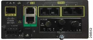
|
|
|
|
|
|
|
807 Low-power Industrial ISR, 4G/LTE multimode for N.America |
||
829 Industrial ISR, Dual LTE US, WiFi, POE, SSD connector, FCC |
For additional information on IR1101, refer to the following URL:
■![]() https://www.cisco.com/c/en/us/support/routers/1101-industrial-integrated-services-router/model.html
https://www.cisco.com/c/en/us/support/routers/1101-industrial-integrated-services-router/model.html
For additional information on IR807, refer to the following URL:
■![]() https://www.cisco.com/c/en/us/support/routers/807-industrial-integrated-services-routers/model.html
https://www.cisco.com/c/en/us/support/routers/807-industrial-integrated-services-routers/model.html
For additional information on IR809, refer to the following URL:
■![]() https://www.cisco.com/c/en/us/support/routers/809-industrial-router/model.html
https://www.cisco.com/c/en/us/support/routers/809-industrial-router/model.html
For additional information on IR829, refer to the following URL:
■![]() https://www.cisco.com/c/en/us/support/routers/829-industrial-router/model.html
https://www.cisco.com/c/en/us/support/routers/829-industrial-router/model.html
For comparison information on Edge Compute products, refer to the following URL:
■![]() https://developer.cisco.com/docs/iox/ - !platform-support-matrix/platform-support-matrix
https://developer.cisco.com/docs/iox/ - !platform-support-matrix/platform-support-matrix
WAN Layer Infrastructure Components
The FAN DA solution uses Cisco FlexVPN as an overlay technology to connect the FAN layer to the Control Center layer leveraging an existing substation WAN infrastructure or Service Provider Cellular services. Depending on the DA design type, the VPN tunnel is established directly between the FAR router or the Cellular DA Gateway router and the Control Center Headend Router (HER).
For cases where the DA FAN traffic needs to be routed and processed within the closest substation, the design would require an additional routing device (ISR4400 or ASR1000) to perform the MAP-T address translation and act as the FlexVPN spoke devices instead of the FAR device.
Substation Network Services
When address translation is required (MAP-T domain per substations), customers can choose between the Cisco ISR4400 series and the Cisco ASR1000 series. Customers can also use virtual routers (CSR1000v) as well if compute resources are available within the substation.
Note: If customers already have routers that can provide these services, then no additional equipment within the substation needs to be acquired.
|
|
|
|
|
|
|
|
|
For additional information on Cisco ISR4331 router, refer to the following URL:
■![]() https://www.cisco.com/c/en/us/products/collateral/routers/4000-series-integrated-services-routers-isr/data_sheet-c78-732542.html - Product-Specifications
https://www.cisco.com/c/en/us/products/collateral/routers/4000-series-integrated-services-routers-isr/data_sheet-c78-732542.html - Product-Specifications
For additional information on Cisco ASR1001-X router, refer to the following URL:
■![]() https://www.cisco.com/c/en/us/products/collateral/routers/asr-1000-series-aggregation-services-routers/datasheet-c78-731632.html?cachemode=refresh
https://www.cisco.com/c/en/us/products/collateral/routers/asr-1000-series-aggregation-services-routers/datasheet-c78-731632.html?cachemode=refresh
For additional information on Cisco CSR1000v router, refer to the following URL:
■![]() https://www.cisco.com/c/en/us/products/collateral/routers/cloud-services-router-1000v-series/datasheet-c78-733443.html
https://www.cisco.com/c/en/us/products/collateral/routers/cloud-services-router-1000v-series/datasheet-c78-733443.html
The following components are optional and recommended as best practices to increase the security of the substation network and provide additional services at the edge of the network.
Customers can deploy security services within the substation network to build a layer of protection between the utility substation WAN, LAN, and FAN layers. A variety of hardened firewalls like Cisco ISA 3000 or ASA5506H-X and non-hardened ASA5500 firewall appliances for substations with HVAC systems are available.
|
|
|
|
|
|
|
|
|
||
|
|
||
|
|
||
|
|
||
|
|
||
|
|
||
|
|
||
|
|
||
|
|
||
|
|
For additional information on Cisco harden ISA3000 firewall, refer to the following URL:
■![]() https://www.cisco.com/c/en/us/support/security/industrial-security-appliance-3000/model.html
https://www.cisco.com/c/en/us/support/security/industrial-security-appliance-3000/model.html
For additional information on Cisco harden ASA5506H-X firewall, refer to the following URL:
■![]() https://www.cisco.com/c/en/us/products/security/asa-firepower-services/ruggedized.html
https://www.cisco.com/c/en/us/products/security/asa-firepower-services/ruggedized.html
For additional information on Cisco non-harden Next-Generation firewalls, refer to the following URL:
■![]() https://www.cisco.com/c/en/us/products/security/firewalls/index.html - ~products
https://www.cisco.com/c/en/us/products/security/firewalls/index.html - ~products
Besides Security services, customers can also deploy substation hardened Compute Gateways using the IC3000 appliance. IC3000 is a dedicated device for Edge Compute applications within the substation layer. Additional appliances can be deployed to meet the growing demand for compute processing at the edge of the network.
|
|
|
|
|
|
IoT FND License for Managing IC3000 industrial compute: 1, 3, 5-year license |
Note: For additional information on Cisco harden IC3000 Compute Gateway, refer to the following URL:
■![]() https://www.cisco.com/c/en/us/products/collateral/routers/3000-series-industrial-compute-gateways/datasheet-c78-741204.html
https://www.cisco.com/c/en/us/products/collateral/routers/3000-series-industrial-compute-gateways/datasheet-c78-741204.html
WAN Control Center
In the Control Center, HER or routers will aggregate all the FlexVPN tunnels from the remote FAR devices or Cellular DA Gateways. More details can be found in Cisco Headend Router Overview.
Headend Layer Infrastructure Components
Application Layer
The Cisco Resilient Network Headend Infrastructure is flexible and modular where it can be integrated in any Utility Control Center network infrastructure. The Headend infrastructure can be deployed as a new infrastructure block separate from the existing utility grid control systems and only allow the telemetry communication and access to the Cisco Resilient network management system to flow between the two systems. Further, some of the headend components can be re-used if the utility has already deployed them. For example, Certificate Infrastructure, IP Address, and Name management tools.
Figure 50 Headend Infrastructure Components
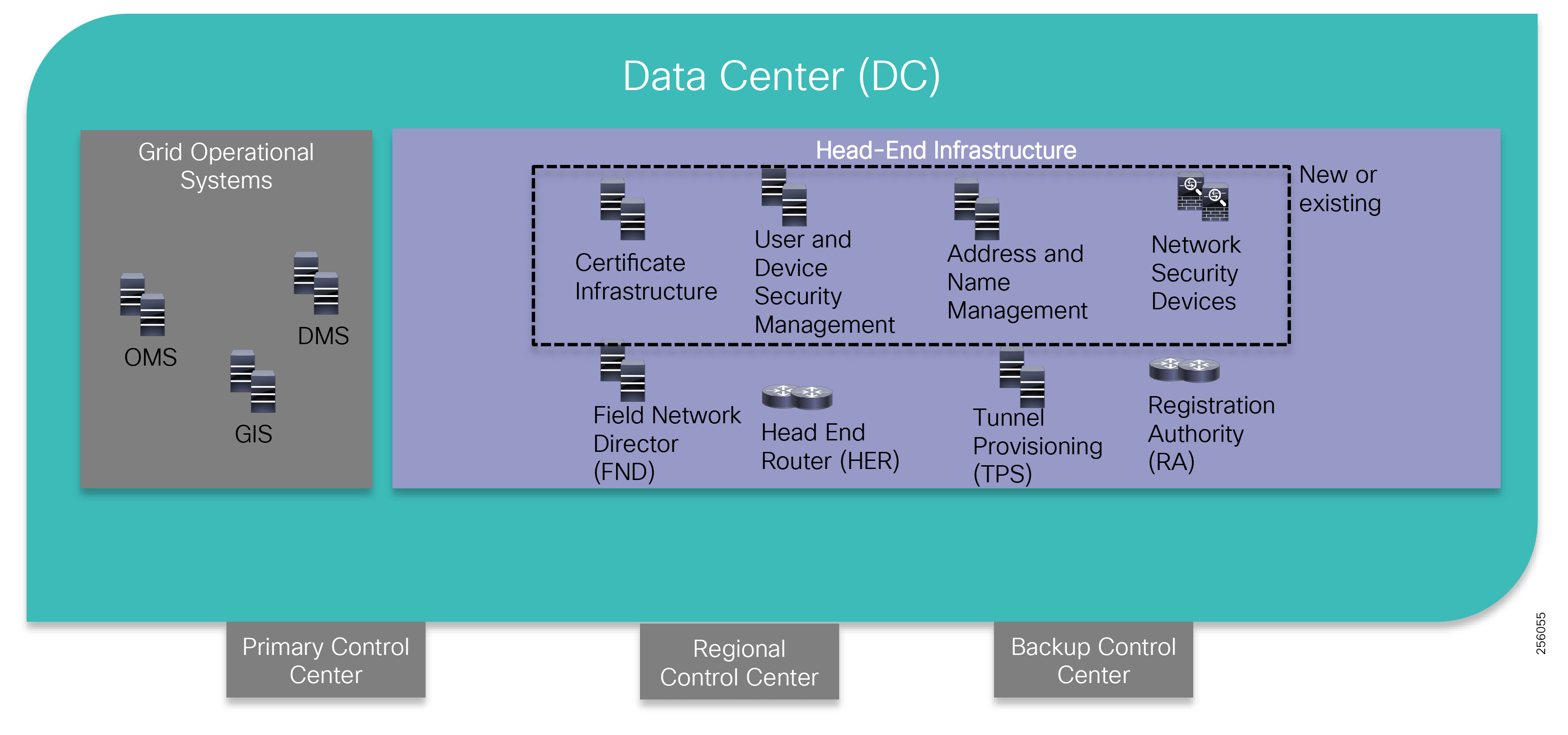
Note: The Headend Infrastructure design is outside of the scope of this document. Please check the SalesConnect for Cisco Field Area Network Full Headend Implementation Guide. If you do not have access, please reach out to your local sales account team.
■![]() https://salesconnect.cisco.com/open.html?c=db570d3f-3212-4659-a306-5f65aeab862b
https://salesconnect.cisco.com/open.html?c=db570d3f-3212-4659-a306-5f65aeab862b
Certificate Infrastructure Overview
The Cisco solution requires a Public Key Infrastructure (PKI) infrastructure to deploy and manage the solution's devices certificates. This approach provides a secure communication infrastructure between components that can also scale to very large number of devices. The Cisco solution requires two types of certificates: RSA for devices with lots of memory: HER or CGR routers and ECC for constrained devices with limited hardware resources: IR510/530, AMI meters. Also, ECC certificates are smaller in size and require less effective bandwidth utilization in the mesh network. Cisco supports the Microsoft Certificate Authority Services part of the Microsoft Windows Server 2016 and 2012.
User and Device Security Management Overview
In order to manage the system users and devices a database service is required. The Microsoft Active Directory services is one of the supported options. It can be easily integrated with Certificate Authority Services.
In addition, a Network Policy Service (NPS) is required to perform device authorization. The Cisco solution uses Cisco Identity Services Engine (ISE) since it offers additional capability over other products, such as ease of integration with the rest of the Cisco infrastructure and VPN services. Alternatively, utilities can use Microsoft NPS services.
Note: For additional information, refer to the following URL:
■![]() https://www.cisco.com/c/en/us/products/security/identity-services-engine/index.html
https://www.cisco.com/c/en/us/products/security/identity-services-engine/index.html
Address and Name Management Overview
In order to ease deployment and address large-scale requirements, Cisco DA solution requires a Dynamic Host Configuration Protocol (DHCP) service to dynamically allocate IPv4 and IPv6 to the infrastructure. A DNS service is also required to easily identify the solution components. DNS plays an important role for Edge Compute applications. Cisco Network Register (CNR) offers both services and has the preferred components. Other services can be used as long as they meet the solution requirements.
Note: For additional information, refer to the following URL:
■![]() https://www.cisco.com/c/en/us/products/cloud-systems-management/network-registrar/index.html
https://www.cisco.com/c/en/us/products/cloud-systems-management/network-registrar/index.html
Field Network Director Overview
The Cisco Field Network Director (FND) is the main solution management system that provides Fault, Configuration, Accounting, Performance, and Security (FCAPS) services.
Note: For additional information, refer to the following URL:
■![]() https://www.cisco.com/c/en/us/products/cloud-systems-management/iot-field-network-director/index.html
https://www.cisco.com/c/en/us/products/cloud-systems-management/iot-field-network-director/index.html
Hardware Security Module or Software Security Module Overview
The FAN solution requires a security module to digitally sign the IPv6 CSMP messages between the FND and Field Devices (IR510) to provide message authenticity. Customers can use a hardware appliance like SafeNet for the best level of security or leverage software functionality as a low-cost alternative. The SSM is licensed under the FND product.
Note: For additional information on SafeNet HSM, refer to the following URL:
■![]() https://safenet.gemalto.com/data-encryption/hardware-security-modules-hsms/safenet-network-hsm/
https://safenet.gemalto.com/data-encryption/hardware-security-modules-hsms/safenet-network-hsm/
Tunnel Provisioning Server Overview
In order to ease the deployment of the solutions and automate the process, Cisco has developed the Tunnel Provisioning Server (TPS) to help provision the initial VPN configuration for the FAR devices. Since it communicates with devices in less secure zones, it acts as a proxy configuration services between the FAR devices and the Cisco FND.
Registration Authority Overview
Cisco routers provide Registration Authorization (RA) services for the initial device onboarding with the Certificate Infrastructure. Network components such as the FAR, Field Devices, and the NMSs receive the proper certificates once they have been authenticated and authorized.
Note: For additional information, refer to the following URL:
■![]() https://www.cisco.com/c/en/us/products/routers/4000-series-integrated-services-routers-isr/index.html
https://www.cisco.com/c/en/us/products/routers/4000-series-integrated-services-routers-isr/index.html
Compute Infrastructure Layer
The Headend software components can be installed on any type of compute infrastructure as long as it follows the product installation hardware requirements. For customers that use Cisco UCS servers or are new to Cisco's server products family, the next section will provide guidance on product selection for installing the various FND components.
Cisco UCS Servers Overview
Note: The data in the table below represents reference numbers for general guidance. For more accurate information, please contact the Cisco account team for the latest product capabilities numbers.
|
|
|
|
|
|

For additional information on FND 4.3 Components Hardware requirements, refer to the following URL:
■![]() https://www.cisco.com/c/en/us/td/docs/routers/connectedgrid/iot_fnd/release_notes/4_3/rn-iot-fnd-4-3.html - 88464
https://www.cisco.com/c/en/us/td/docs/routers/connectedgrid/iot_fnd/release_notes/4_3/rn-iot-fnd-4-3.html - 88464
For ordering and server configuration information on UCS C220 M5, refer to the following URL:
■![]() https://www.cisco.com/c/dam/en/us/products/collateral/servers-unified-computing/ucs-c-series-rack-servers/c220m5-sff-specsheet.pdf
https://www.cisco.com/c/dam/en/us/products/collateral/servers-unified-computing/ucs-c-series-rack-servers/c220m5-sff-specsheet.pdf
For ordering and server configuration information on UCS C240 M5, refer to the following URL:
■![]() https://www.cisco.com/c/dam/en/us/products/collateral/servers-unified-computing/ucs-c-series-rack-servers/c240m5-sff-specsheet.pdf
https://www.cisco.com/c/dam/en/us/products/collateral/servers-unified-computing/ucs-c-series-rack-servers/c240m5-sff-specsheet.pdf
For ordering and server configuration information UCS C480 M5, refer to the following URL:
■![]() https://www.cisco.com/c/dam/en/us/products/collateral/servers-unified-computing/ucs-c-series-rack-servers/c480-m5-high-performance-specsheet.pdf
https://www.cisco.com/c/dam/en/us/products/collateral/servers-unified-computing/ucs-c-series-rack-servers/c480-m5-high-performance-specsheet.pdf
Network Layer
Customers can leverage the existing switching and routing infrastructure within their Control Center or acquire new equipment to build a dedicated environment for the FAN DA solution. For the latter case, customers can select products listed in the next sections.
Switching and Routing Infrastructure Overview
Cisco has a large portfolio of switching products for Enterprise as well as Industrial customers. For Control Center switching infrastructure, the Catalyst 9200 switching family is a great platform to use because of its cost and the support for network automation (SD-Access). The Catalyst 9200 switches offers two types of chassis: one that is modular and will allow customers to upgrade the uplink ports down the road and another one with a fixed configuration. Both versions are stackable, which allows the platform to be used for small or large Control Center networks.
For Control Centers interconnected by a private WAN and where customers would like to distribute precision timing from the Control Center to remote Substations, the Cisco IE5000 switches can be used to complement the Catalyst 9200 switching infrastructure. The Cisco IE 5000 switch can be connected directly to a GPS interface and, through an additional license, can work as a PTP Grandmaster.
|
|
|
|
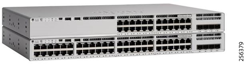

|
|
|
|
Catalyst 9200L 24-port data only, 4 x 10G, Network Advantage |
||
For more information on Catalyst 9200 switches, refer to the following URL:
■![]() https://www.cisco.com/c/en/us/products/collateral/switches/catalyst-9200-series-switches/nb-06-cat9200-ser-data-sheet-cte-en.html
https://www.cisco.com/c/en/us/products/collateral/switches/catalyst-9200-series-switches/nb-06-cat9200-ser-data-sheet-cte-en.html
For more information on IE 5000 switches, refer to the following URL:
■![]() https://www.cisco.com/c/en/us/products/collateral/switches/industrial-ethernet-5000-series-switches/datasheet-c78-734967.html
https://www.cisco.com/c/en/us/products/collateral/switches/industrial-ethernet-5000-series-switches/datasheet-c78-734967.html
Cisco Headend Router Overview
To secure communication over any type of utility WAN implementations, the Cisco DA solution uses an overlay VPN technology. Therefore, the solution becomes agnostic to the transport infrastructure, maintaining the same design functionality, which simplifies the manageability of the network.
The HERs terminate the VPN tunnels from the FAN devices, in particular the FAR. For large deployments, multiple HERs can be configured to operate in a cluster. Cisco has a large portfolio of WAN routers that match any deployment size of the DA solution.
Customer can choose different models from the same routing product family for consistency and ease of management. The following products can be use as HER devices.
Note: The data in the table below represents reference numbers (single dimension) for general guidance. For more accurate information, please contact the Cisco account team for the latest product capabilities numbers.
|
|
|
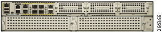
|
|
|
|
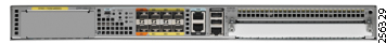


|
|
|
Note: For CSR1000v product details, please reach out to your Cisco sales account team.
Network Security Devices Overview
Network Firewalls and end nodes agents provide good security boundaries between the Grid Operation Systems as well as the different components of the Cisco HE that communicate with devices outside the utility physical security boundary. Cisco offers a comprehensive portfolio of security network appliances and software applications.
Note: The data in the table below represents reference numbers (single dimension) for general guidance. For more accurate information, please contact the Cisco account team for the latest product capabilities numbers.
|
|
|
|
|
|
|
|
|


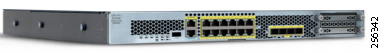
|
|
|
For additional information on ASAv, refer to the following URL:
■![]() https://www.cisco.com/c/en/us/products/collateral/security/adaptive-security-virtual-appliance-asav/datasheet-c78-733399.html?cachemode=refresh
https://www.cisco.com/c/en/us/products/collateral/security/adaptive-security-virtual-appliance-asav/datasheet-c78-733399.html?cachemode=refresh
For additional information on NGFWv, refer to the following URL:
■![]() https://www.cisco.com/c/en/us/support/security/firepower-ngfw-virtual/tsd-products-support-series-home.html
https://www.cisco.com/c/en/us/support/security/firepower-ngfw-virtual/tsd-products-support-series-home.html
For additional information on FRP2110, refer to the following URL:
■![]() https://www.cisco.com/c/en/us/products/collateral/security/firepower-ngfw/datasheet-c78-736661.html
https://www.cisco.com/c/en/us/products/collateral/security/firepower-ngfw/datasheet-c78-736661.html
For additional information on FRP4110, refer to the following URL:
■![]() https://www.cisco.com/c/en/us/products/collateral/security/firepower-ngfw/data_sheet-c78-736661.html
https://www.cisco.com/c/en/us/products/collateral/security/firepower-ngfw/data_sheet-c78-736661.html
Solution Deployment Models for DA
This chapter includes the following major topics;
■![]() Utility SCADA Systems Architecture Overview
Utility SCADA Systems Architecture Overview
■![]() Cisco DA Feeder Automation Solution based on Standard Unlicensed 900MHz ISM Band
Cisco DA Feeder Automation Solution based on Standard Unlicensed 900MHz ISM Band
■![]() Cisco DA Feeder Automation Solution using Public Cellular Service (3G/4G)
Cisco DA Feeder Automation Solution using Public Cellular Service (3G/4G)
■![]() Cisco DA Feeder Automation based on Hybrid Design: Cellular & 900MHz ISM
Cisco DA Feeder Automation based on Hybrid Design: Cellular & 900MHz ISM
Utility SCADA Systems Architecture Overview
Traditionally, SCADA system architecture is centralized and uses a single tier between the SCADA Primary stations that are located in the Primary and Back-up Control Centers and the SCADA clients (which are typically RTUs located in the substations). This architecture worked well as communication technology evolved and made its way onto the distribution grid network for asset monitoring and control. Figure 51 is an example of such system.
Figure 51 Traditional, Centralized SCADA System Architecture
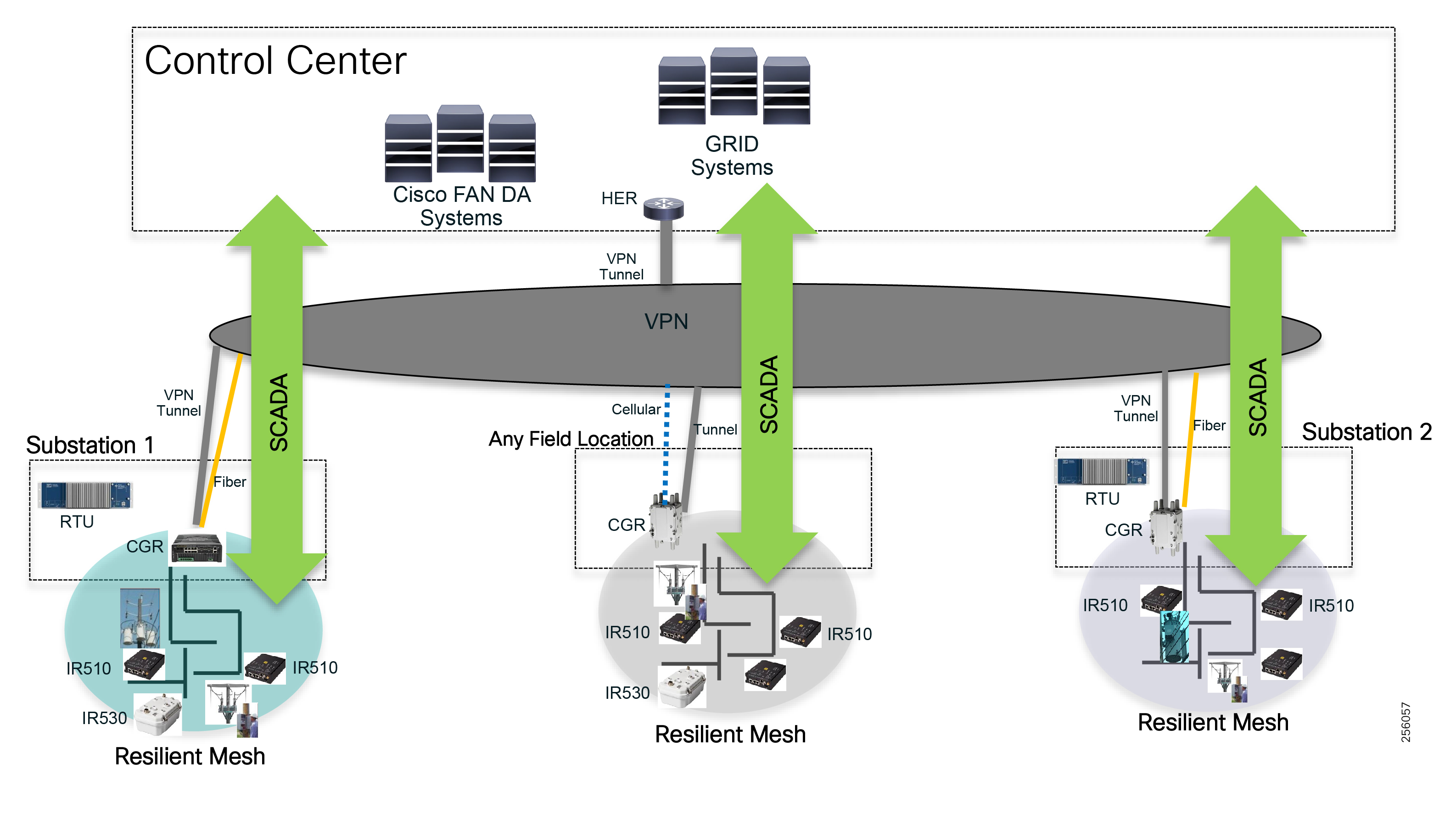
However, with the introduction of Distributed Energy Resources (DER) and new requirements to increase the reliability of the distribution grid, customers in both the European and North America markets have started considering a two-tier SCADA architecture, which is sometimes called the Distributed SCADA architecture. It moves some of the decision logic from the Control Centers closer to the substations in order to achieve better system reaction times and make the system more flexible to changes in the grid.
Figure 52 Distributed SCADA System Architecture
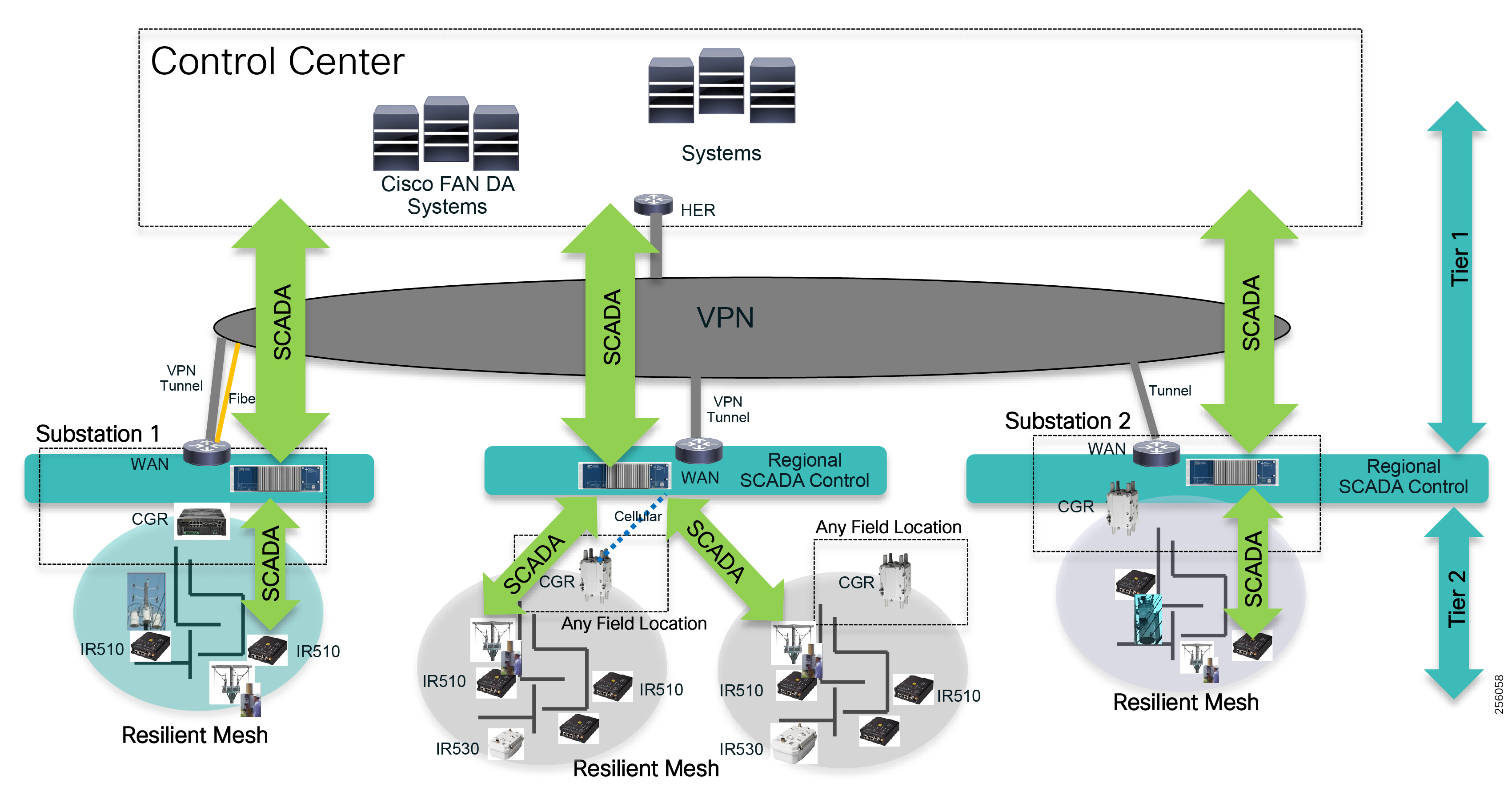
In the next couple of sections, you will learn about the different Cisco FAN DA designs available for implementation that will support both types of SCADA architectures. The Private Network solution is a better option if you have a distributed SCADA architecture or believe you will be moving towards one in the near future.
Cisco DA Feeder Automation Solution based on Standard Unlicensed 900MHz ISM Band
Utility customers that prefer a private solution can opt to run their Distribution Automation systems using only the Cisco Resilient Mesh design based on the ISM open license 900 MHz band. This design eliminates any dependencies on third party services and allows customers to operate the network from provisioning to configuration management to the troubleshooting point of view. It offers a lower operation cost model since there is no monthly reoccurring service cost for the transport service and it eases the regulatory compliance process. It is also less vulnerable to weather-related or crowding events that affect a cellular service. This design is well suited for large or small utilities and it can be deployed in urban or rural territories. It supports both centralized and distributed SCADA systems.
For utilities with a distribution substation fiber-rich WAN network, the FAR can be installed within the substation yard. This type of implementation is better suited for Distributed SCADA systems or future Smart Grid implementations where the Grid control needs to be regionalized for fast control response.
The design can leverage a VPN service over the existing substation WAN if encryption is required or if the WAN is not IPv6 capable.
Figure 53 DA Design Based on 900MHz ISM Band Solution [4003] 256299 or not?
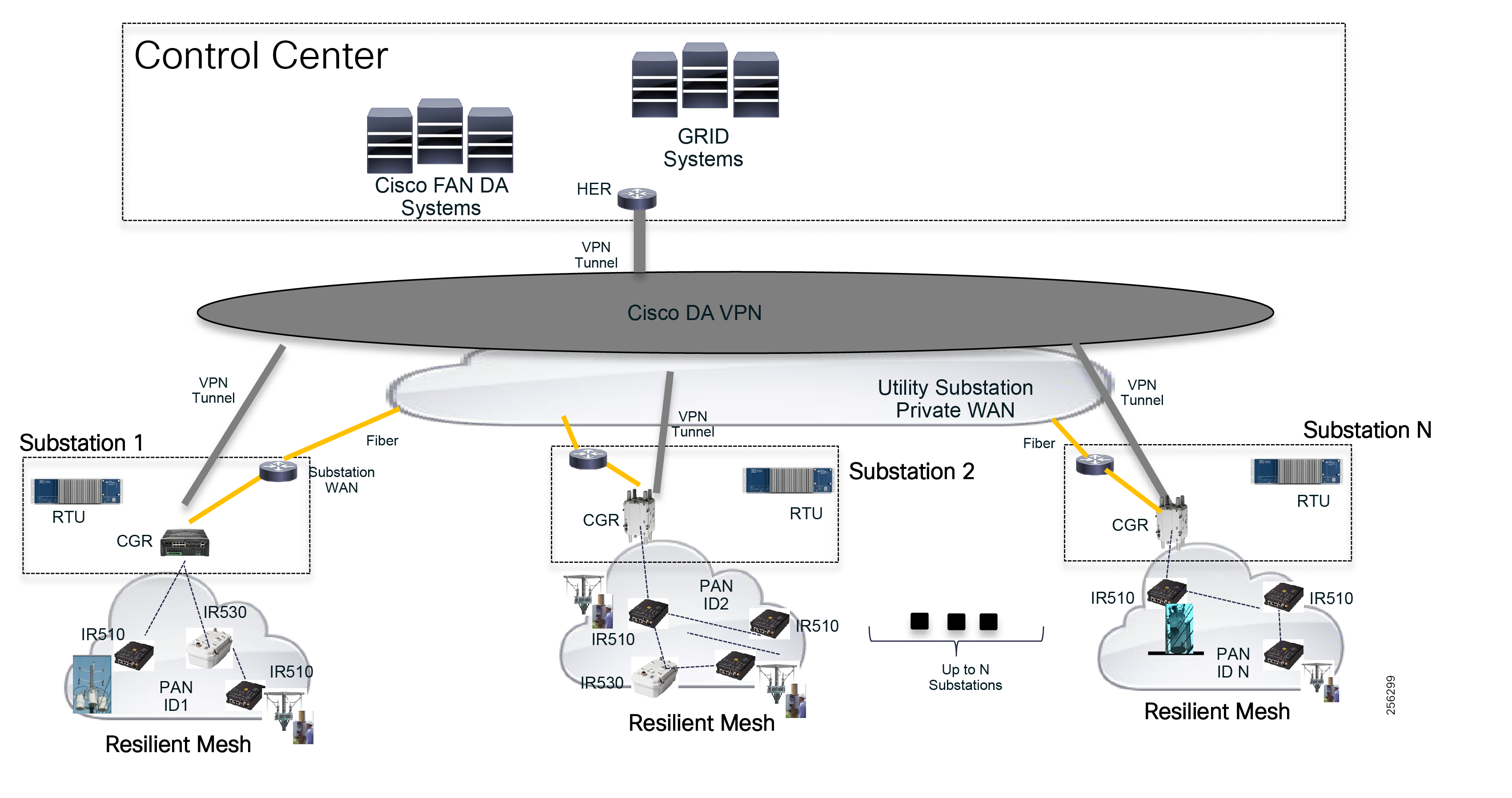
For substations that don't have a high-speed WAN connection, customers can choose to use the Cisco Outdoor Wi-Fi mesh solution to backhaul the Resilient Mesh traffic towards the closest substation that has a fiber WAN connection.
The Wi-Fi backhaul can use a mesh topology similar to the Resilient Mesh or Point-to-Point Wi-Fi links to extend the substation connectivity. An additional benefit of this design is that customer can deploy DA applications that require high bandwidth and low latency like ultra FLISR based on IEC61850 or microPMUs. The FARs can be installed anywhere in the field where the utility has assets.
Figure 54 Wi-Fi Backhaul for Location without Fiber
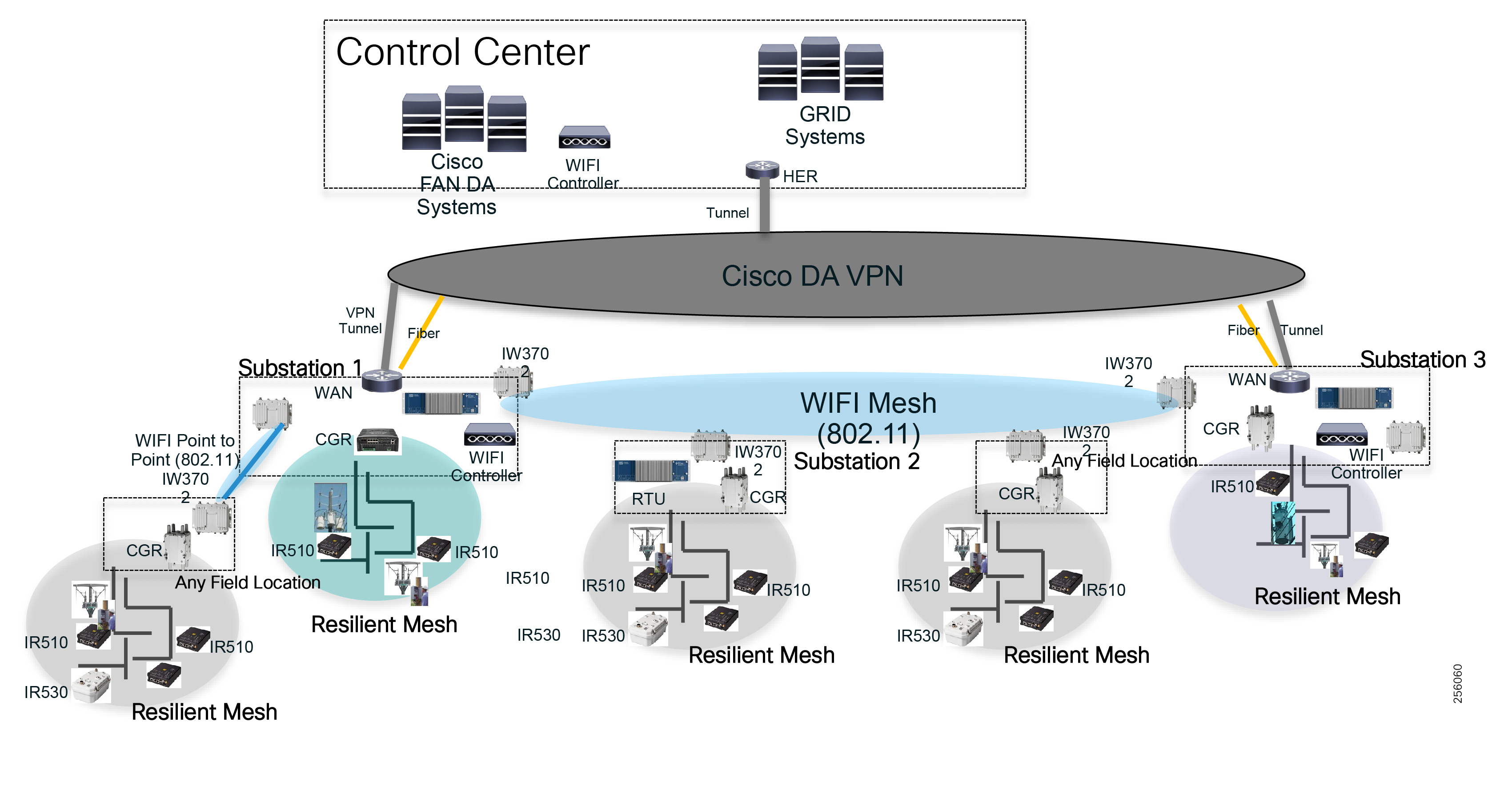
Cisco DA Feeder Automation Solution using Public Cellular Service (3G/4G)
As an alternative technology to the 900 MHz ISM band, customers can use a design that is a based only on the Cisco Cellular products for DA applications. This design has a higher OpEx due to reoccurring Cellular services, but for certain countries where the 900MHz band is not supported, Public Cellular is the only reasonable option.
Besides cost, customers need to take into consideration the cellular base station congestion, which can be temporarily caused by crowded events or permanently caused by over-subscription when cell has peaked its original planned size. Public Cellular service does not offer service priority among its tenants. Cellular technology uses asymmetric bandwidth, which was designed to offer higher download link speed than upload link speed. The DA traffic profile is opposite to the Cellular Service link design where most of the traffic and bandwidth requirements are using the upload link speed. The SCADA primary system makes small size requests and the grid field device responds with larger amounts of data.
Each distribution automation grid asset will be connected to a Cisco DA gateway that will build a VPN tunnel over the Service Provider Cellular network towards the Control Centers to encrypt the data. Service Providers support both hub-and-spoke topology as well as an any-to-any topology for peer-to-peer communication. The Cisco VPN services can be also configured to match the Service Provider service topology for optimal traffic flow. This design will accommodate both Centralized and Distributed SCADA implementations. For the latter scenario, a cellular DA gateway might be required to be installed within the distribution substation even if the substation has fiber or high-speed connectivity. The traffic from nearby field devices could share the same cellular base station with the Substation DA Gateway, which reduces the latency communication for a two-tier SCADA implementation. The Substation DA Gateway could also be used as a back-up solution for the substation primary WAN link. Without cellular connectivity, the traffic between grid field devices to nearby substation RTUs will hairpin at the Control Center since that is the only place that interconnects the Fiber and Cellular networks.
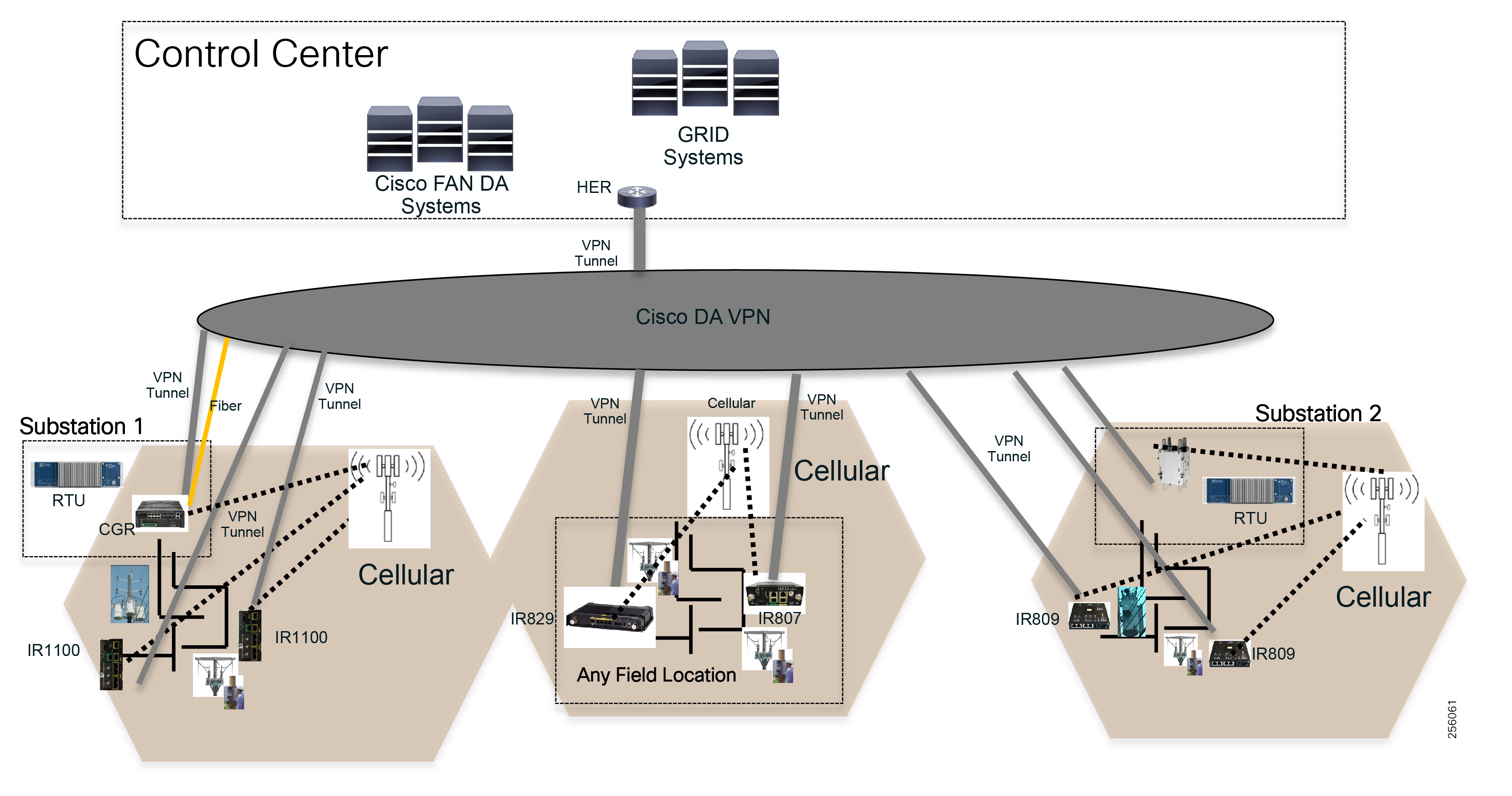
Cisco DA Feeder Automation based on Hybrid Design: Cellular & 900MHz ISM
For customers that prefer a Distribution Automation design based on private provider-managed Cellular services, but with a territory where the cellular coverage is not well developed or has pockets of no-service coverage, or where certain locations requires more bandwidth than what the ISM band can offer, a hybrid DA design with cellular and Resilient Mesh is more appropriate. The 900Mhz solution will complement the cellular by allowing customers to automate feeders that are located in new development areas or rural areas that lack cellular service. Customers can install the FARs closer to the edge of the cellular coverage area and extend the network connectivity services using Field Devices and the ISM 900 MHz band. Figure 56 is an example of such deployment.
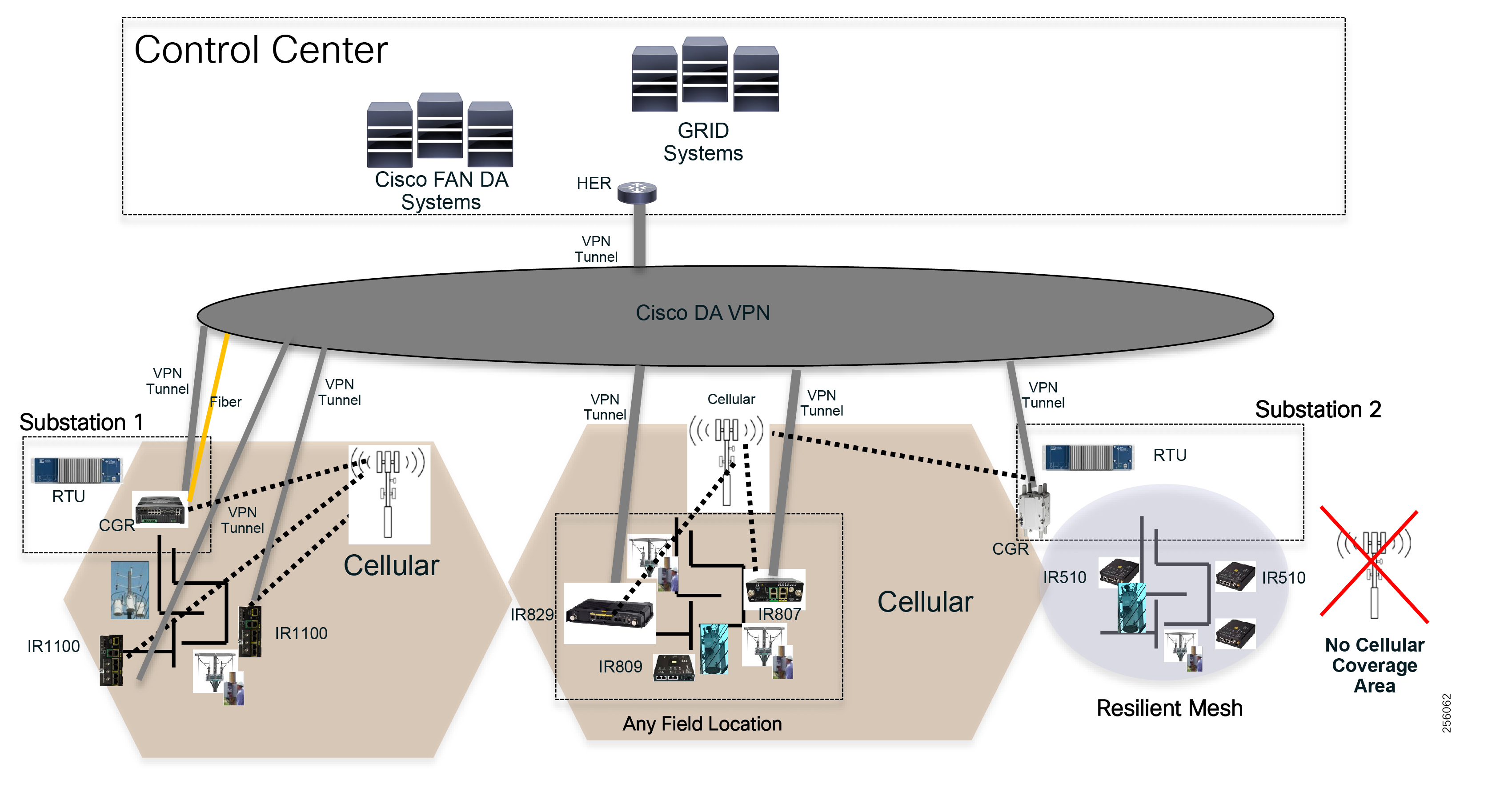
Design Considerations for DA Feeder Automation Deployments Based on 900MHz ISM Band Solution
This chapter, which focuses on the technical design considerations a network architect or engineer needs to understand in order to successfully develop a detail design for their FAN network based on the 900MHz ISM band, includes the following major topics:
■![]() Network Availability and Resiliency
Network Availability and Resiliency
This first version of the document will focus on designs for which the FAR or CGR routers are installed within the utility's substation premises and leverage the utility's Substation Private WAN as backhaul connectivity.
The design makes the following assumptions:
■![]() Customers have a private WAN deployed to all their substation locations.
Customers have a private WAN deployed to all their substation locations.
■![]() FAR devices will be installed within the substation premise.
FAR devices will be installed within the substation premise.
■![]() FAR devices backhaul connectivity will be via Ethernet: fiber or copper to the Substation LAN or WAN block.
FAR devices backhaul connectivity will be via Ethernet: fiber or copper to the Substation LAN or WAN block.
■![]() Customer's SCADA system uses a centralized architecture and traffic is tunneled from the FAR router back to the Control Center HER using a single MAP-T domain.
Customer's SCADA system uses a centralized architecture and traffic is tunneled from the FAR router back to the Control Center HER using a single MAP-T domain.
■![]() The Control Center network design is out of scope.
The Control Center network design is out of scope.
Figure 57 High Level Design Topology
Future releases of the document will also cover deployments where the FAR routers are deployed anywhere in the field and use Public Cellular Services for backhaul connectivity.
The overall design effort will be broken down into the three main solution's layers:
■![]() FAN Resilient Mesh Infrastructure
FAN Resilient Mesh Infrastructure
The main emphasis will be on the FAN Resilient Mesh Infrastructure layer, but will also briefly touch on the remaining layers. References to other Design Guides that include the necessary details for a technical person to develop an end-to-end design are also provided.
End Devices Connectivity
Today, most of the Distribution Automation grid devices are connected to the Resilient Mesh communication equipment via legacy, low speed, and asynchronous serial interfaces RS232 or RS485. In order to transport the serial traffic from grid devices to the grid management systems located in the Control Centers over an IP network, Resilient Mesh uses a feature called Raw Socket to encapsulate the serial traffic in IPv4 packets over a UDP or TCP session. In this case, each field device (IR510) requires an IPv4 address to establish a session with the SCADA DMS servers or other terminating devices.
Figure 58 Serial Grid Device Connectivity
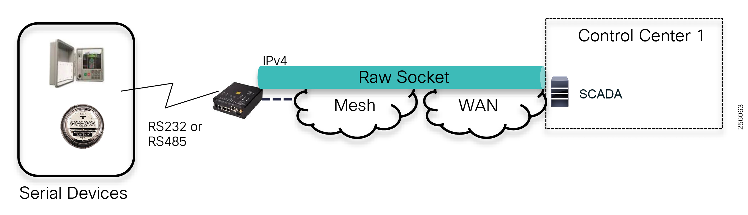
Distribution grid devices that support Ethernet interfaces can be connected to the IR510 Ethernet 0 port using IPv4 or IPv6 protocol.
Figure 59 Ethernet Grid Device Connectivity
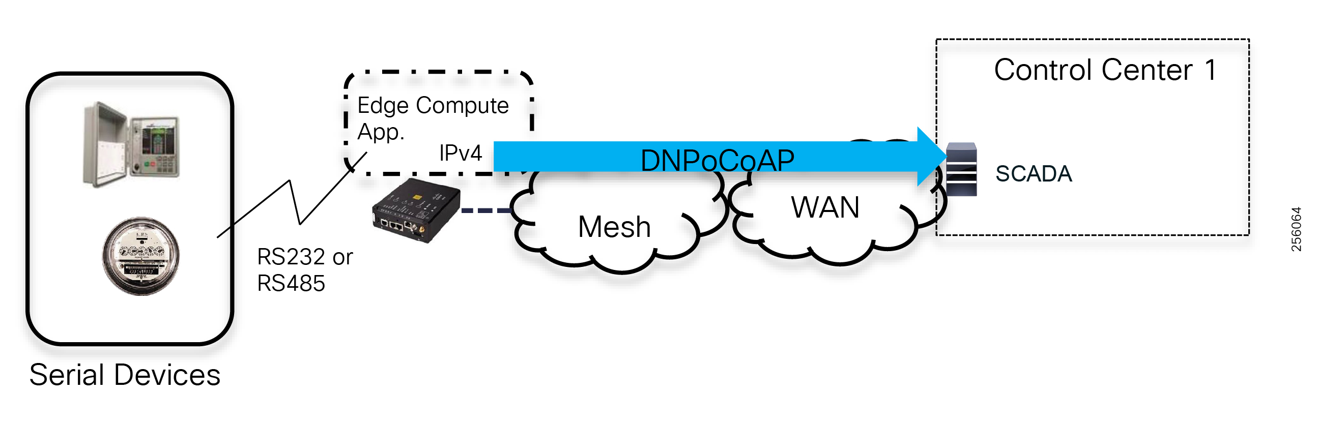
With the introduction of Edge Compute capabilities, customers can now run grid applications local to the distribution grid devices. These enable customers to perform more advanced grid operations where legacy grid devices have limited capabilities. In addition, customers can leverage IoT architectures and protocols like Constrained Application Protocol (CoAP), MQ Telemetry Transport (MQTT), and Data Distribution Service (DDS) to deploy a middleware message bus where data manipulation can be performed. For example, data from different distribution grid device types can be normalized and exchanged between multiple devices or systems across the Resilient Mesh. For these scenarios, the Edge Compute application container will require additional IPv4 addresses and IPv6 in the future.
Note: Customers are responsible for the developing or acquiring third party Edge applications that can be hosted on the Cisco FAN DA devices. Cisco provides a management solution for deploying and monitoring such applications at scale.
Figure 60 Edge Compute Application Connectivity
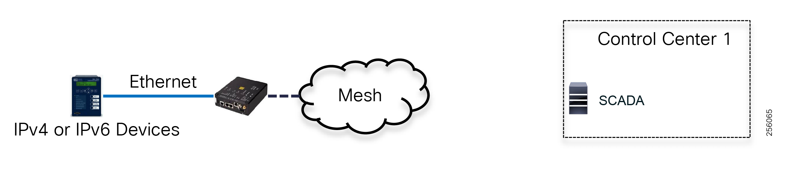
IP Address Schema
FAN Resilient Mesh Layer
Mesh Address Space
The Cisco Resilient Mesh solution was developed with a forward-looking mindset to overcome IPv4 address exhaustion as well as provide support for millions of end devices and sensors. Therefore, routing within the mesh is based on native IP6. Since IPv4 is still prevalent for the end devices, especially in the Utility Industry where adaption of IPv6 is in its infancy stage because of lack of equipment vendor support, the Resilient Mesh also leverages industry standards for address translation between IPv4 and IPv6 as traffic flows over the mesh.
In summary, the mesh requires both IPv4 and IPv6 networks in order to transport the end grid devices traffic.
The size of the mesh network address space, number of subnets will be based on the following factors:
a.![]() Utility number of end devices: capacitor bank controllers, recloser, etc.
Utility number of end devices: capacitor bank controllers, recloser, etc.
b.![]() Utility number of take out points or exit points out of the mesh. This depends on the utility's substation WAN fiber presence as well as end device density for an area since the ratio of Field Devices per FAR needs to be considered.
Utility number of take out points or exit points out of the mesh. This depends on the utility's substation WAN fiber presence as well as end device density for an area since the ratio of Field Devices per FAR needs to be considered.
c.![]() Number of Field Devices per Mesh PAN ID, including expected number of devices that would perform PAN migration
Number of Field Devices per Mesh PAN ID, including expected number of devices that would perform PAN migration
d.![]() Number of mesh range extenders required to close any RF signal coverage gaps
Number of mesh range extenders required to close any RF signal coverage gaps
e.![]() Number of edge compute applications and number of locations where application(s) will be deployed
Number of edge compute applications and number of locations where application(s) will be deployed
f.![]() Future growth, additional Smart Grid use cases: DER, etc.
Future growth, additional Smart Grid use cases: DER, etc.
In general, each Cisco mesh device requires the following address types based on the design redundancy and resiliency requirements, substation WAN support for IPv6, and customer requirements for edge compute applications
|
|
|
|
|
|
|
|
|
|||||
|
|
|||||
|
|
IPv6 as IPv4 uses two type of network addresses:
■![]() Globally Unicast Addresses (GUA)
Globally Unicast Addresses (GUA)
Global IPv6 prefix: Obtained through one of the five Regional Internet Registries (RIR): AFRINIC, APNIC, ARIN, LACNIC, or RIPE. The entity requesting the prefix from the RIR must be registered with the RIR as either a Local Internet Registry (LIR) or end-user organization. As an alternative, a global prefix might be obtained from an ISP.
A utility should consider registering as a LIR to obtain its own IPv6 prefix and therefore be fully independent from any churn in the ISP addressing architecture.
RIRs define policies regarding allocation of an IPv6 prefix and the prefix size. A RIR prefix allocation is by default ::/32 prefix for a LIR, and ::/48 for an end-user organization. The RIR policies also define how larger or smaller prefixes can be allocated to a LIR and an end-user organization.
Note: For additional information on RIR, refer to the following URL:
■![]() https://www.ripe.net/publications/docs/ripe-707
https://www.ripe.net/publications/docs/ripe-707
A justification that is based on the number of sites and hosts must be given for the non-default allocation. The number of FAN sites and subnets drive the decision to register as a LIR or as an end-user organization and further justify the requests made for prefix allocation and size.
ULA IPv6 prefix: A unique local address (ULA) IPv6 prefix, documented in RFC 4193, is allowed to be "nearly unique." It starts with a FC00::/7 value but the following 41 bits, global routing ID, allow an addressing space far greater than the 3-private IPv4 prefixes (10.0.0.0/8, 172.16.0.0/12, 192.168.0.0/16) documented in RFC 1918. The size of the global routing ID effectively produces a pseudo "uniqueness." Note, however, that no central registration of ULA prefixes currently exists.
The main differences between selecting a global or ULA IPv6 prefix are the following:
■![]() A global prefix requires registration to the RIR either as LIR or as an end-user organization. This requires paper work and fees before getting and justifying an IPv6 prefix allocation. A ULA does not require this registration.
A global prefix requires registration to the RIR either as LIR or as an end-user organization. This requires paper work and fees before getting and justifying an IPv6 prefix allocation. A ULA does not require this registration.
■![]() Filtering at the border of the utility routing domain:
Filtering at the border of the utility routing domain:
■![]() A ULA IPv6 prefix must NEVER be advertised to the Internet routing table.
A ULA IPv6 prefix must NEVER be advertised to the Internet routing table.
■![]() A global IPv6 prefix or portions of its address space might be advertised to the Internet routing table and incoming traffic MUST be properly filtered to block any undesirable traffic.
A global IPv6 prefix or portions of its address space might be advertised to the Internet routing table and incoming traffic MUST be properly filtered to block any undesirable traffic.
■![]() Internet access: A ULA-based addressing architecture requires the IPv6-to-IPv6 Network Prefix Translation (IPv6 NPT, RFC 6296) device(s) to be located at the Internet border. Remote workforce management use cases, such as third-party technicians connecting to their corporate network from a FAN site or an FND operator using the Google map features, might require Internet access. For web access, web proxies can be a solution.
Internet access: A ULA-based addressing architecture requires the IPv6-to-IPv6 Network Prefix Translation (IPv6 NPT, RFC 6296) device(s) to be located at the Internet border. Remote workforce management use cases, such as third-party technicians connecting to their corporate network from a FAN site or an FND operator using the Google map features, might require Internet access. For web access, web proxies can be a solution.
■![]() Once an IPv6 prefix has been allocated for the FAN, a hierarchy numbering the regions, districts, sites, subnets, and devices must be properly structured. IPv6 addressing is classless, but the 128-bit address can be split among a routing prefix, upper 64 bits, the Interface Identifier (IID), and the lower 64 bits. A hierarchical structure eases the configuration of route summarization and filtering.
Once an IPv6 prefix has been allocated for the FAN, a hierarchy numbering the regions, districts, sites, subnets, and devices must be properly structured. IPv6 addressing is classless, but the 128-bit address can be split among a routing prefix, upper 64 bits, the Interface Identifier (IID), and the lower 64 bits. A hierarchical structure eases the configuration of route summarization and filtering.
Cisco supports both address space implementations and highly recommends customers that use the Global Unicast Address space to filter the DA solution's IPv6 prefixes at the company's internet security border.
For customers that choose to use ULA address space, it's good to ensure that NAT66 is not enabled between the DA IPv6 prefixes and the company internet global prefixes in order to avoid routing traffic from the internet in the DA infrastructure.
Besides the unicast addresses, the FAN DA solution also requires IPv6 Multicast address allocation. The firmware for the FAN DA devices is done using multicast to optimize the distribution of the software over the LLN.
Mesh Layer 3 Boundaries
The Cisco Resilient Mesh is a Layer 3 IPv6-routed network. Each Field Area Router (CGR) mesh radio interface (WPAN) is a Layer 3 boundary and defines a Personal Area Network (PAN) that shares the same Layer 3 network prefix among all devices associated with the that PAN ID. Therefore, the address prefix length assigned to each CGR WPAN interfaces is directly related to the maximum number of field grid devices connected to a PAN, the number of Range Extenders (IR530) within the PAN, and the expected field devices that can migrate to the PAN from adjacent PANs.
Figure 62 CGR WPAN and IPv6 Address Assignment
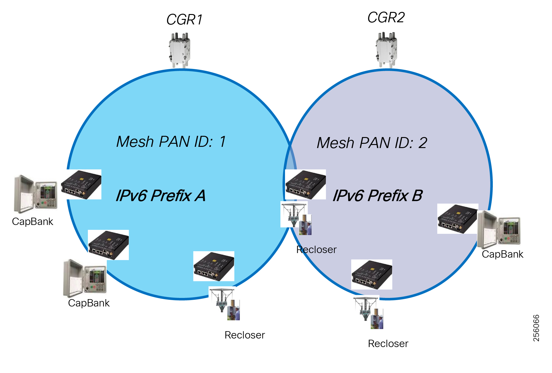
For FAR High Availability (HA) designs, a direct Ethernet link is required between the two CGR routers that are used as a heartbeat link to detect CGR failure and for state replication of the WPAN state as described in FAN Infrastructure Layer. The HSRP protocol runs between routers; therefore, at a minimum, the IPv4 subnet prefix should be a /29.
Address Translation
For scenarios where the end grid devices are connected via serial interfaces or the Ethernet using IPv4 to the Field Devices (IR510), address translation is necessary to translate IPv4 packets into IPv6 packets and vice versa and allow end-to-end communication between islands of IPv4 networks over the Mesh IPv6 network, as shown in Figure 63. Tunneling is another method, but due to additional overhead associated with encapsulation, it's not suited for Low power and Lossy Networks (LLNs).
Figure 63 Address Translation (IPv4 and IPv6)
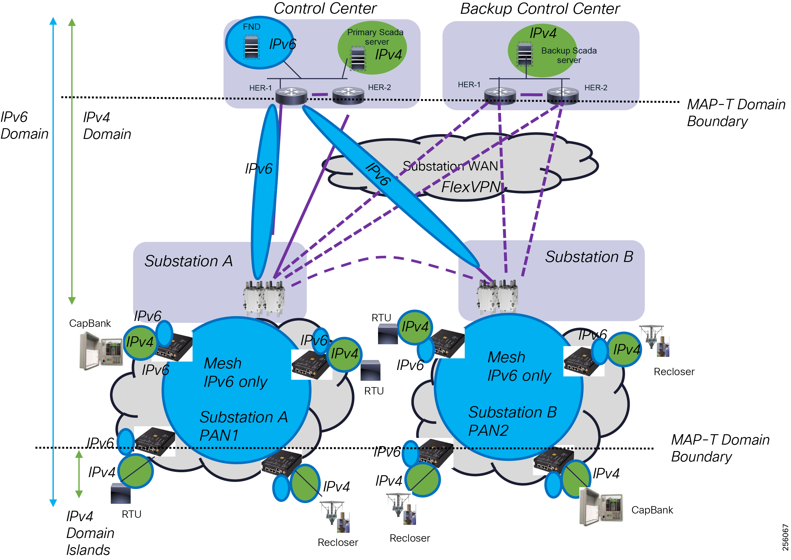
The Cisco Resilient Mesh network uses the IETF Network Address Translation and Protocol Translation (NAT-PT), in particular MAP-T, which is a double stateless NAT64 translation. The benefit of stateless address translation is that Cisco devices don't have to maintain a translation state and also allow DA devices to migrated within mesh without affecting the traffic flow over new paths.
Note: Currently, the software version 6.0 running on the IR510 support up to 15 unique NAT44 entries.
The MAP-T uses some key concepts: MAP-T domains, mapping rules: Default Mapping Rule (DMR), Basic Mapping Rules (BMR), Forwarding Mapping Rules (FMR), and Border Router (BR).
Note: For additional MAP-T information, refer to the following URL:
■![]() https://www.cisco.com/c/en/us/td/docs/ios-xml/ios/ipaddr_nat/configuration/15-mt/nat-15-mt-book/iadnat-mapt.pdf
https://www.cisco.com/c/en/us/td/docs/ios-xml/ios/ipaddr_nat/configuration/15-mt/nat-15-mt-book/iadnat-mapt.pdf
Based on the utility SCADA architecture and the traffic patterns, MAP-T can be implemented in two types of designs:
–![]() Single MAP-T domain per HER, which is suited for Centralized SCADA where all traffic from the field grid devices flow to the Control Center SCADA systems, and peer-to-peer communication between grid devices is not required or supports high latency requirements. Depending on the FlexVPN design, the HER will learn from FAR routers (CGR) each PAN host routes (/128) to the IR510 devices. If WAN FlexVPN is not configured, spoke-to-spoke communication traffic will hairpin at the Control Center. This design is suited for small-to-medium size networks with thousands of grid devices.
Single MAP-T domain per HER, which is suited for Centralized SCADA where all traffic from the field grid devices flow to the Control Center SCADA systems, and peer-to-peer communication between grid devices is not required or supports high latency requirements. Depending on the FlexVPN design, the HER will learn from FAR routers (CGR) each PAN host routes (/128) to the IR510 devices. If WAN FlexVPN is not configured, spoke-to-spoke communication traffic will hairpin at the Control Center. This design is suited for small-to-medium size networks with thousands of grid devices.
–![]() One MAP-T domain per substation, which is optimal for use cases like FLISR where peer-to-peer communication is required and has low latency requirements; therefore, the traffic does not have to hairpin at the Control Center HER device. This design requires an additional routing device in the substation to perform the Border Router functions. The advantages of these design is that it scales to millions of devices, has optimal routing, and host routes are not advertised in the WAN block, only summaries.
One MAP-T domain per substation, which is optimal for use cases like FLISR where peer-to-peer communication is required and has low latency requirements; therefore, the traffic does not have to hairpin at the Control Center HER device. This design requires an additional routing device in the substation to perform the Border Router functions. The advantages of these design is that it scales to millions of devices, has optimal routing, and host routes are not advertised in the WAN block, only summaries.
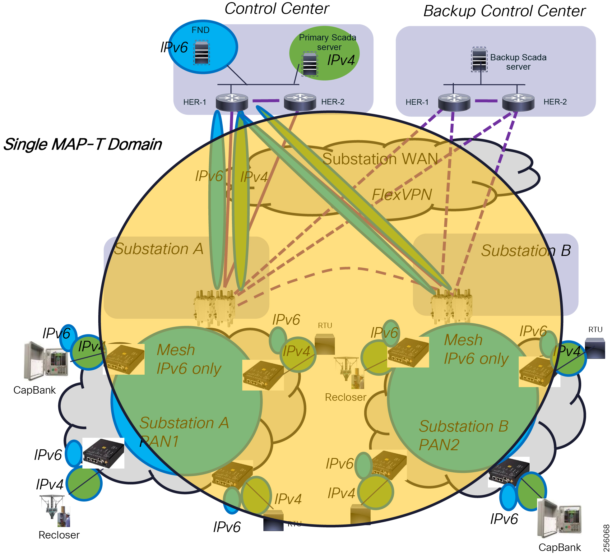
Figure 65 Multiple MAP-T Domains
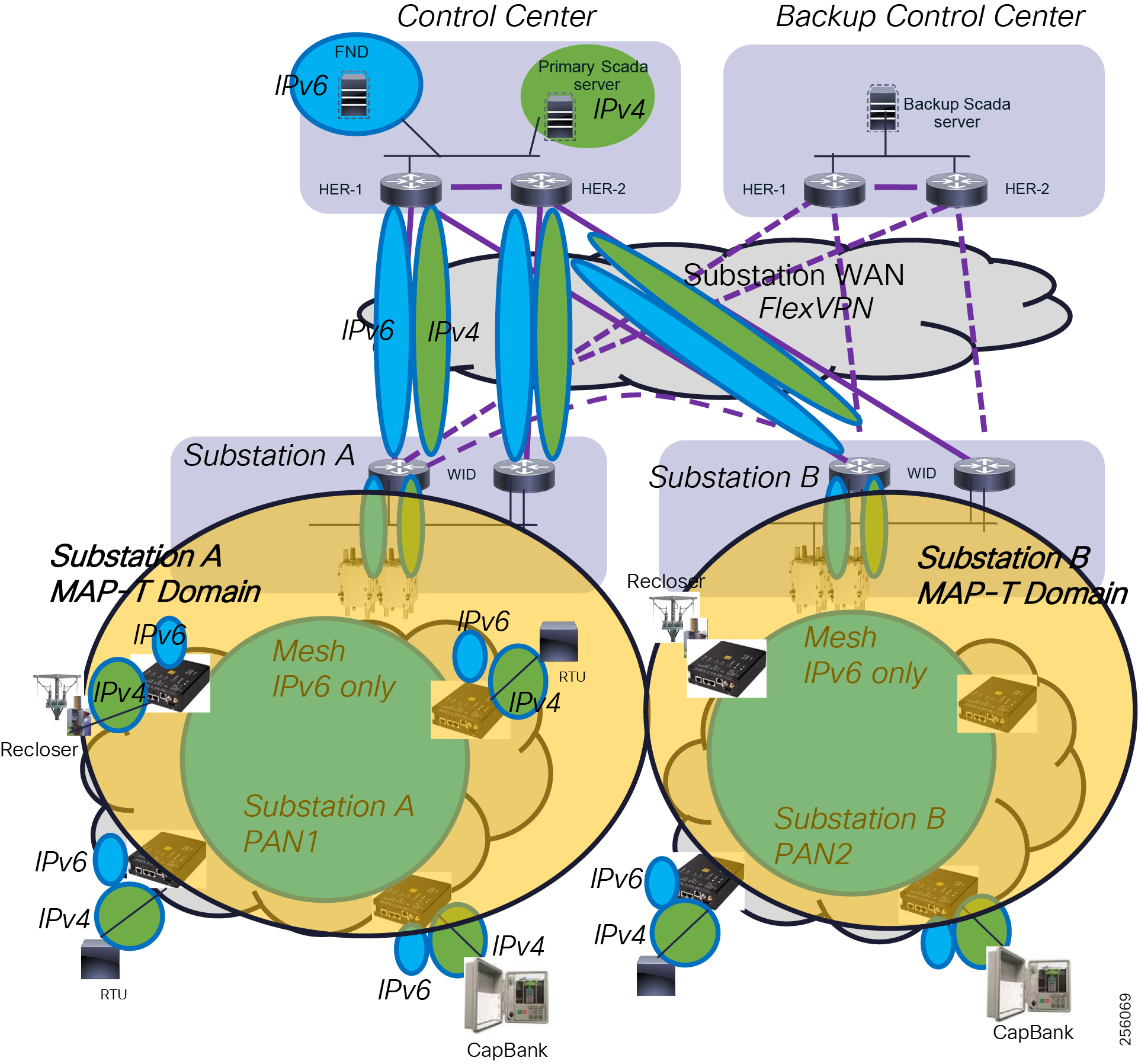
|
|
|
|
|
For grid equipment upgrades or new grid equipment installation, customers should look at selecting vendor equipment that supports IPv6 protocol or at least work with the grid equipment vendors to add IPv6 capabilities to their devices. This will help the industry to adopt faster IPv6 protocol and simplify the FAN DA design by allowing end devices to communicate natively using IPv6.
Wide Area Network Layer
The FAN WAN layer uses a VPN overlay design to make the solution agnostic to the different utility customer distribution WAN network designs. The VPN services runs between the FAR devices or the Substation WAN routers and the HERs located in the Control Center.
Customers can allocate any private IPv4 and IPv6 address space as long as the space is unused within the company. The best approach is to configure the VPN devices in a dual-stack configuration.
The size of the address space depends on the following factors:
■![]() Redundancy requirements for the HER within a Control Center
Redundancy requirements for the HER within a Control Center
Note: For additional information regarding DA WAN FlexVPN design, refer to the following URL:
■![]() https://www.cisco.com/c/en/us/td/docs/solutions/Verticals/Distributed-Automation/Secondary-Substation/DG/DA-SS-DG/DA-SS-DG-doc.html
https://www.cisco.com/c/en/us/td/docs/solutions/Verticals/Distributed-Automation/Secondary-Substation/DG/DA-SS-DG/DA-SS-DG-doc.html
Headend Layer
The Headend infrastructure address spaces depends heavily on the existing IP address schema used in the Control Center. In general, the new FAN DA Headend infrastructure requires both IPv4 and IPv6 address space.
|
|
|
|
|
Note: For additional information regarding the Cisco Field Area Network Full Headend Implementation Guide, refer to the following URL. If you don't have access to the resource, contact the local sales account team.
Fragmentation and Reassembly
FAN Resilient Mesh Layer
End Devices MTU
The grid devices connected using the Ethernet interfaces use a Maximum Transmission Unit (MTU) of 1500 Bytes. The Ethernet standard does not support fragmentation and it is the responsibility of the sender device to fragment packets over 1500 Bytes. If a link has a smaller MTU between the sender and receiver devices, in case of VPN designs or Cellular transport service, then the network device in the path will perform network fragmentation, which is an intensive resource process that causes network service degradation or packets to be simply dropped.
With IPv6 based on RFC8200, network devices do not perform fragmentation anymore; the RFC guidance is that the minimum IPv6 MTU configurable on an interface is 1280 bytes, which means any packets smaller than that are almost guaranteed not to be fragmented. For transport interfaces with MTU lower than 1280 bytes, an additional protocol must be implemented to perform fragmentation and reassembly below Layer 3. This was the case with the initial IEEE 802.15.4 where the Layer 2 MTU was 127 bytes, and the mesh was using the 6LoWPAN Adaptation Layer to perform fragmentation and reassembly. Further, upper layer protocols and applications should not send packets larger than 1500 Bytes unless they are sure the receiver can reassemble packets above 1500 Bytes.
In order to avoid these type of scenarios, customers acquiring new grid equipment should ensure at minimum that the equipment can interpret IPv4 ICMP message type 3 - "Destination Unreachable" with Code 4 - "Fragmentation Needed and Don't Fragment was Set" from DA Gateways and fragment the packets in smaller sizes based on the lowest Path MTU in the ICMP message. Ideally, utilities should buy equipment that has Path Maximum Transmission Unit Discovery (PMTUD) capabilities. PMTUD is even more critical for grid equipment supporting IPv6 communications due to the lack on network fragmentation.
For legacy grid devices that do not support PMTUD, the customer can manually set MTU on the device interface to the smallest value of the MTU on the communication path after taking into consideration all protocols headers overhead in case of the WAN VPN. For protocols like DNP3, this is not a concern since DNP3 data link MTU is 292 Bytes.
Resilient Mesh MTU
The DA Gateways and FAR devices support PMTUD over the mesh radio and can signal to end devices when the application needs to reduce the packet size to avoid network fragmentation.
Originally, the IEEE 802.15.4 Physical Service Protocol Unit (PSDU) maximum size was 127 Bytes and the Cisco Mesh was using 6LoWPAN adaptation layer that was performing fragmentation/reassembly functions between the Layer 3 IPv6 and Mesh Layer 2.
The IEEE 802.15.4-2015 standard increased the original PSDU of 127 Bytes to 2047 Bytes so the 6LoWPAN adaptation layer does not perform fragmentation and reassembly. It only does header compression for IR510 within the mesh.
Figure 66 shows that the grid devices MTU should not be set higher than 1472 Bytes to avoid packet drops if end devices do not support PMTUD. The CGR Maximum Mesh MTU is 1500 Bytes of which 28 Bytes are used by IPv6 headers. Over the WAN, assuming it supports full Ethernet 1500 MTU, the IPSec and GRE header add up to about 112 Bytes when using IPv4 as transport and 164 Bytes for IPv6 transport. To accommodate for future growth as encryption algorithms evolve, it is recommended to set both IPv4 and IPv6 MTU to 1300 Bytes.
The smallest link MTU will be over the WAN FlexVPN tunnel; therefore, in order to avoid fragmentation or packet drops, customers should also set the Grid Field Devices MTU for both IPv4 and IPv6 to 1300 Bytes when devices do not support PMTUD. If devices support PMTUD, then it's best to leave the Grid field devices to use their default MTU and rely on the PMTUD features that works with UDP and TCP applications.
Note: DNP3 and Modbus use small PDU size and are not prone to fragmentation. It's possible that other device management protocols could benefits from PMTUD or manual configuration of the MTU on the Grid field device.
Note: When packets are small, it will take less airtime to transmit and be open for packet errors due to interference or collision.
Figure 66 End Device Maximum MTU for Ethernet Connectivity
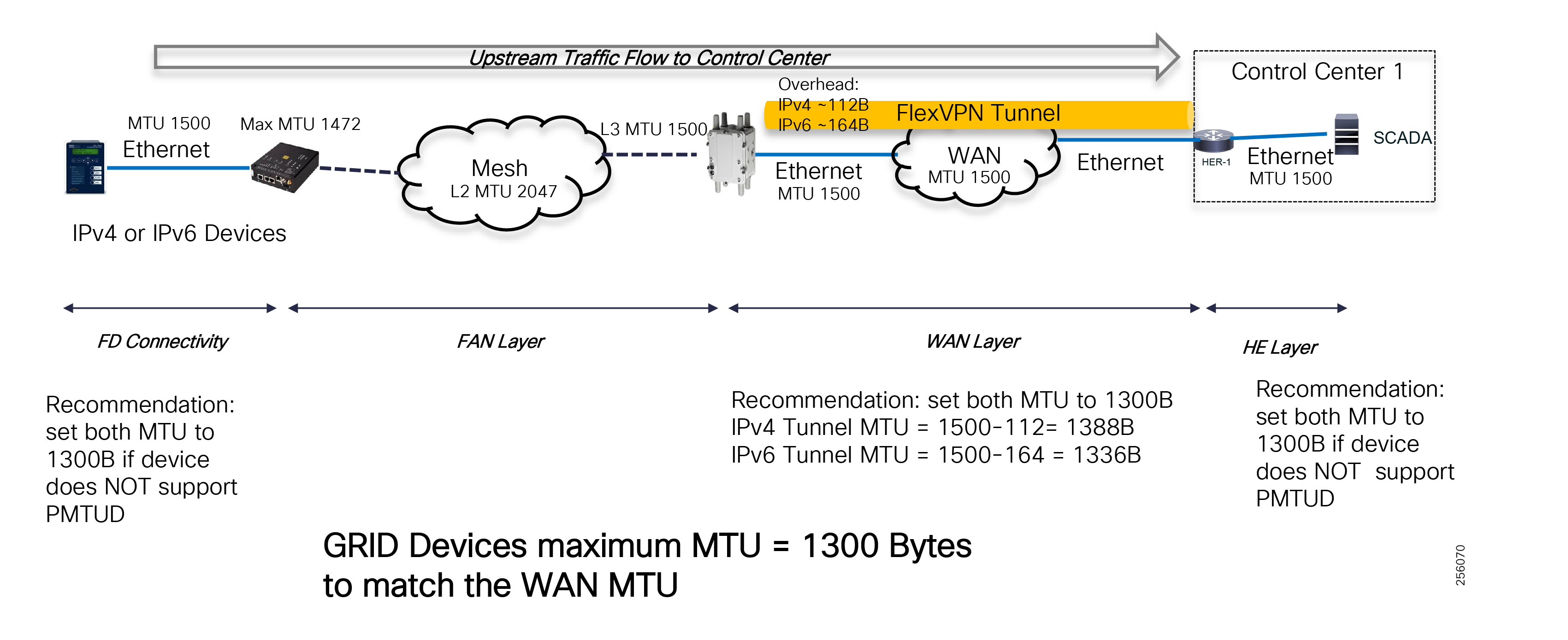
Grid field devices connected via Serial interface will use the Raw Socket feature to packetize the DNP serial data over the IP network. The Raw Socket session can be configured to use UDP or TCP for transport, but UDP is the recommend configuration since Mesh has a built-in reliability function at Layer 2 as well as the DNP protocol.
A Raw Socket session from the DA Gateways can be terminated in the Control Center in multiple scenarios. For IP SCADA systems, the Raw Socket can be terminated directly on the DMS Front End Processor (FEP) system as depicted in Figure 67. When configuring Raw Socket over UDP, customers should set the Maximum Packet Length for the session to something that matches the protocol used. For example, for DNP set the Packet Length to be around 292 Bytes.
Note: To avoid DMS packet reassembly, enable the message interleaving delay on the Grid field devices serial port.
Figure 67 Raw Socket Packet Length for Serial Connectivity
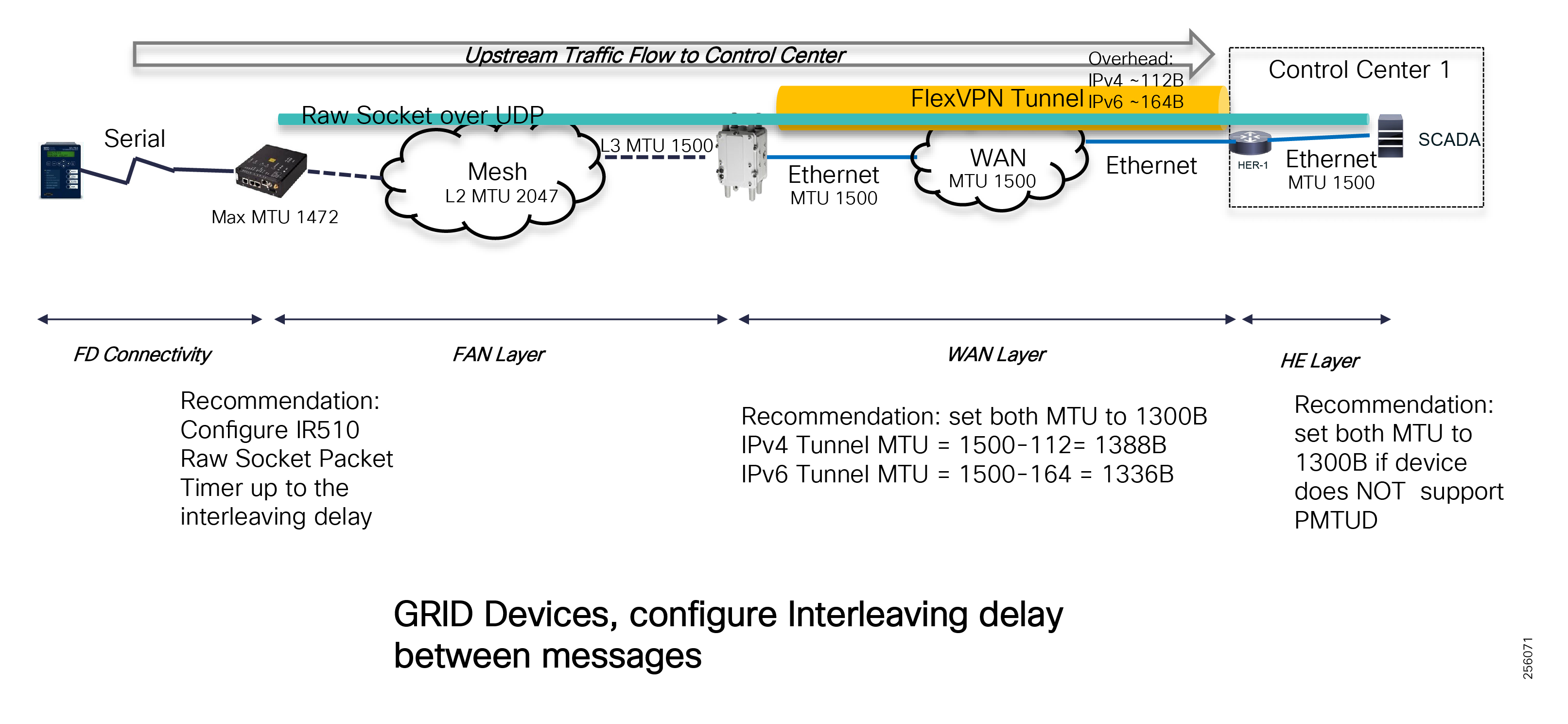
Note: The default Packet Timer is 10 milliseconds.
For traffic towards the Grid field devices (downwards), the MTU packet size depends on the Mesh routing mode configuration. For Storing Mode, the same Upwards principal apply as described in Figure 68.
When the Mesh is configured for Non-Storing Mode, then the FAR devices will insert a Source Routing Header and its size depends on the depth of the mesh, the hop count to destination.
Figure 68 Non-Storing Mode MTU Considerations
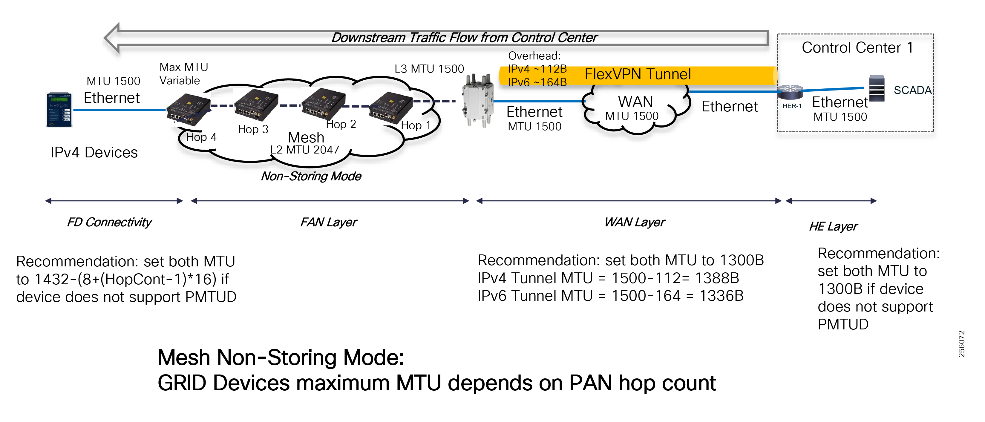
WAN MTU
The substation WAN device's MTU depends on the WAN device connectivity interface type (Ethernet or Cellular) and the type of WAN transport service used (Private WAN, Managed MPLS service or Public Cellular Service).
Regardless of the type of SCADA architecture used, the WAN device physical interface MTU should reflect the WAN transport service MTU.
The FlexVPN spokes, either the FAR or substation WAN devices, and the Tunnel interface MTU should be set based on the lowest MTU of the Physical interface or Transport Service minus the FlexVPN protocols overhead. The same configuration should be applied on the HER Virtual Tunnel interface. As an example, Figure 69 shows the Tunnel MTU size when the WAN supports the full Ethernet MTU of 1500 Bytes.
Figure 69 WAN MTU Considerations
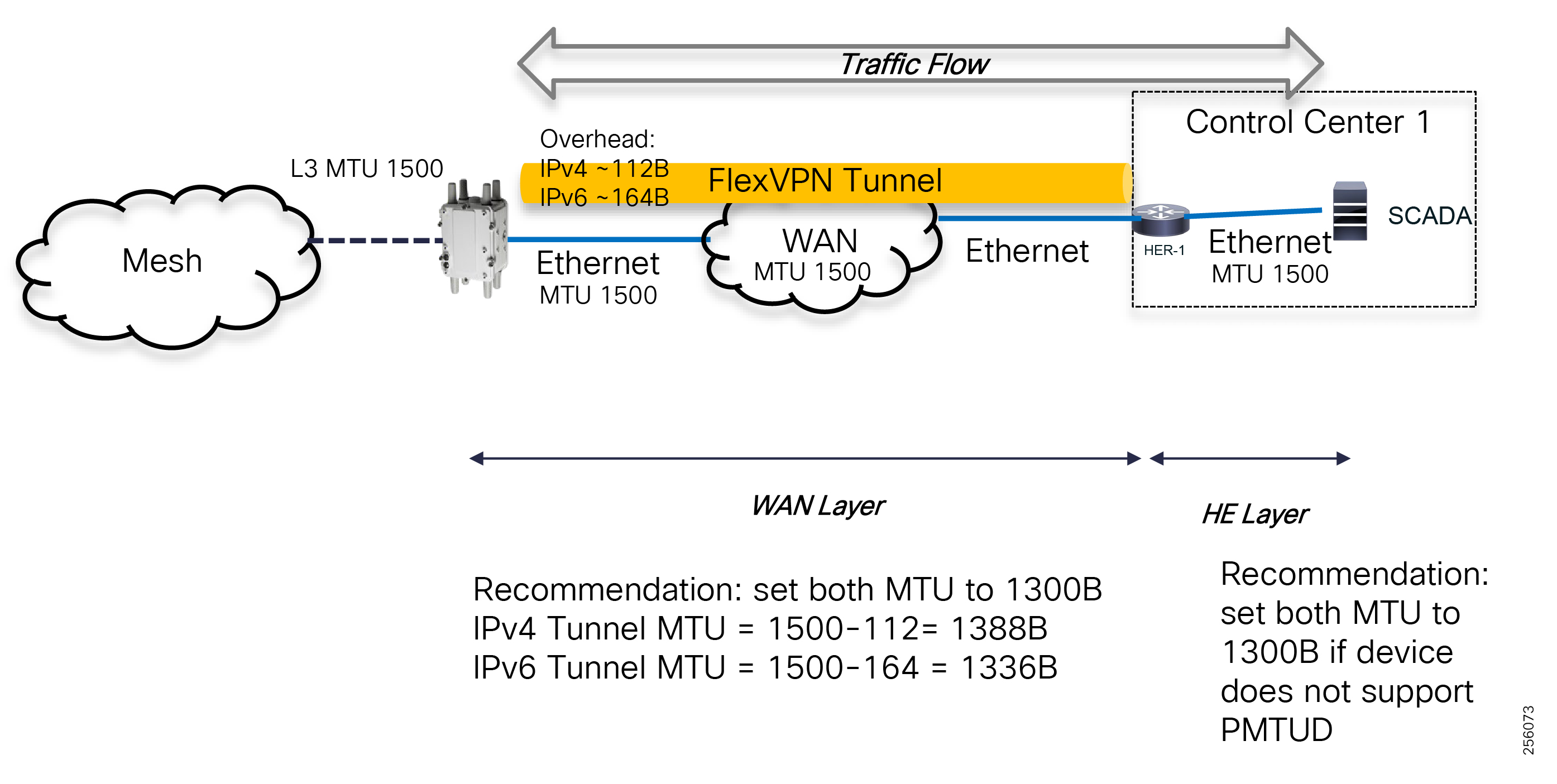
Headend Infrastructure MTU
In the Control Center, Ethernet is the de-facto standard for connectivity and most of the systems run full operating systems that support PMTUD functionality; therefore, customers can use the default Ethernet MTU of 1500 Bytes.
Network Routing
The Cisco FAN Distribution Automation solution uses multiple routing protocols to facilitate end-to-end communication between the Grid field devices, Substation Systems and the Control Center Grid Management Systems.
Traffic from Grid devices directly attached to the DA Gateways radios is routed using IPv6 based on the shortest and most reliable path towards the FAR device, which is the gateway out of the radio Mesh network. The Resilient Mesh network also supports peer-to-peer communication within the mesh for the DA FLISR solution that might require recloser coordination.
The Mesh routing protocol is dynamic and specifically designed to deal with RF changing conditions of the links and route traffic around links with poor performance. Cisco implemented innovative functionality (such as peer-to-peer communication, adaptive modulation, and adaptive data rate) and was the first in the industry to give utility customers the functionality required for Distribution Automation systems. These features are detailed in RF Design Development Process.
In the WAN, customer will need to run static or dynamic routing protocols for the transport layer to allow FAR routers to build a VPN tunnel back to the HER in the Control Center. The routing protocol selection depends on the WAN transport service, Layer 2 or Layer 3, but the Cisco FAN DA can work over any scenario. VPN can be established over an IPv4 as well as an IPv6 transport service.
Once the VPN overlay is established over the transport service, customers could leverage the FlexVPN IKEv2 Dynamic Routing feature to advertise the Mesh DA Gateways IPv6 prefixes and IPv4 prefixes from the Substation network to the VPN aggregation router (HER). IKEv2 Dynamic Routing is light in traffic usage and can scale to a large number of FlexVPN spokes. Customers can also use dynamic routing protocols for implementations where bandwidth utilization is not an issue (for example, private Fiber WAN). For large-scale deployments, it is recommended that customer use the BGP routing protocol instead of EIGRP.
OSPF is not recommended as an overlay routing protocol because of its scalability limitations. If one of the FAR backhaul connection flaps, it will creates a large amount of control plane exchange since the entire OSPF database needs to be updated on all the other FAR devices.
Traffic entering or leaving the radio mesh between IPv4 devices will always be routed through the MAP-T Border Router. For Centralized SCADA architecture, the HER is configured to be the MAP-BR. For distributed SCADA deployments, the substation WAN router acts as the MAP-T BR.
The DA Gateways and substation prefixes are only advertised within the VPN and are hidden, protected from the transport infrastructure which improve the solution security when the transport is untrusted. Customers can also enable multicast routing within the VPN layer even if the transport does not support it.
For high availability deployments, customers can use different types of VPN designs as highlighted in 5.8.2 WAN Infrastructure section.
Figure 70 shows the end-to-end routing architecture. Note that the second FlexVPN is optional and can be implemented if customers would like to have separate VPN failure domains between the Primary and Back-up Control Center.
Within the Control Center, HERs participate in the site local IGP routing domain based on the existing implementation. The dynamic routing protocol typically is a customer choice based on their engineering team skills.
Figure 70 FAN DA End-to-End Routing Architecture
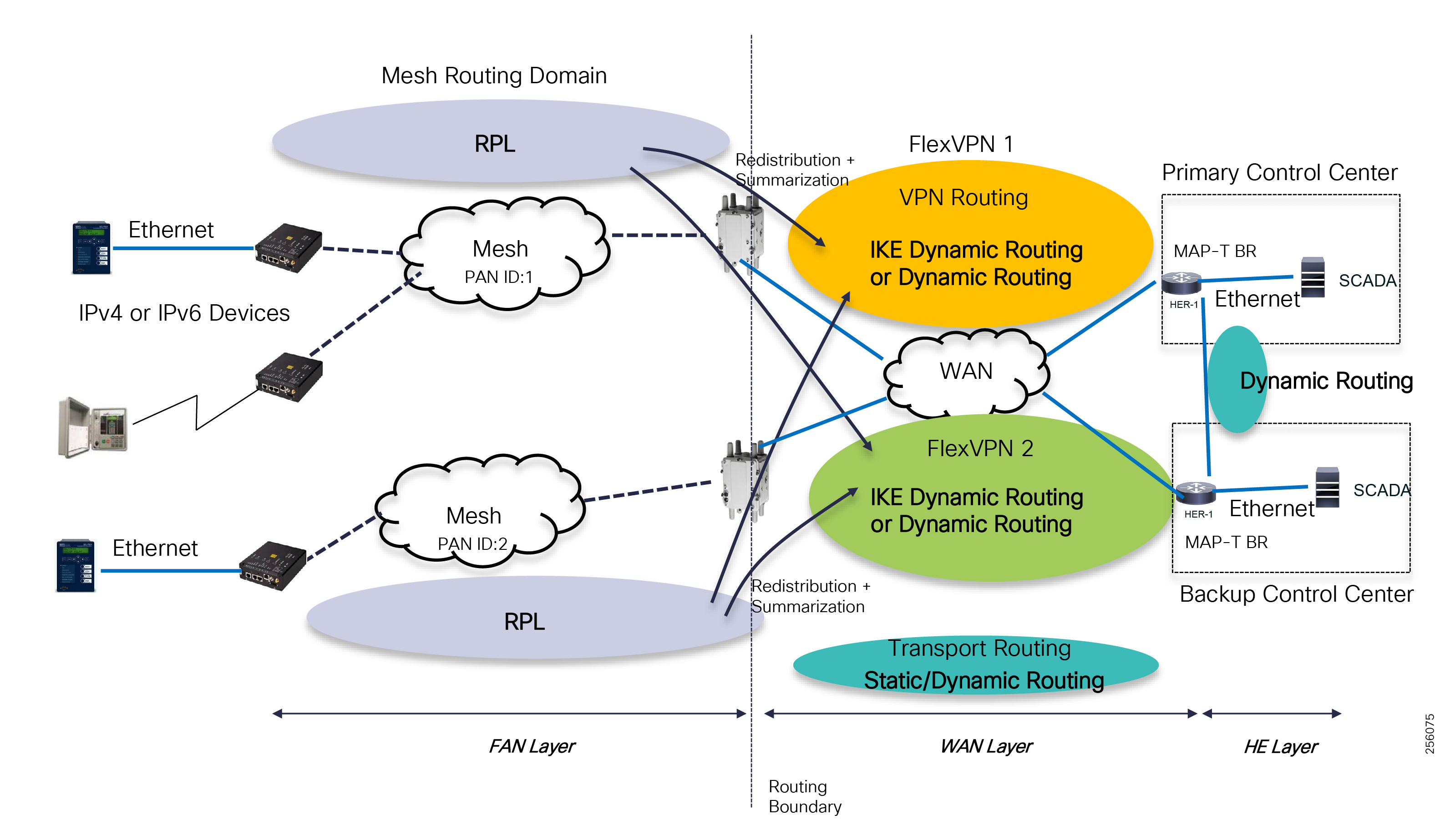
Mesh Routing (RPL)
Routing in the Resilient Mesh (6LoWPAN) is done per PAN, where each IPv6 subnet leverages the distance vector routing protocol name (RPL): IPv6 Routing Protocol for Lossy and Low Power networks, RFC 6550.
The Cisco Resilient Mesh routing is autonomous and does not require user input. It is optimized to operate and support the DA applications that require more bandwidth, low latency, reliable transmission and peer-to-peer communication. Administrators have only a few request parameter list (RPL) parameters that can be configured on the FAR devices.
Note: For more information on Resilient Mesh RPL configuration, use the Configuration Guide documentation.
■![]() https://www.cisco.com/c/en/us/td/docs/routers/connectedgrid/cgr1000/ios/modules/wpan_cgmesh/b_wpan_cgmesh_IOS_cfg.html
https://www.cisco.com/c/en/us/td/docs/routers/connectedgrid/cgr1000/ios/modules/wpan_cgmesh/b_wpan_cgmesh_IOS_cfg.html
DA Gateways (IR510/IR530) act as RPL nodes while the FAR device (CGR) acts as an RPL Directed Acrylic Graph (DAG) Root. The RPL protocol was designed to run on constrained devices with limited resources (memory, communication, and computation), dynamic environments like radio networks and at large scale: thousands of devices in a routing domain. RPL builds a forwarding tree topology similar in concept to Spanning-tree where alternate links and paths are "pruned" from the forwarding plane and not used, unless they become a better path towards the FAR than the current route or there is a failure of the active path. The topology is called Destination Oriented Directed Acrylic Graph (DODAG) and it is a directed graph, single rooted at the CGR, the destination, with no cycles or loops. Each topology node has a Rank number associated to show its position within the graph with respect to the root, the CGR. The Rank value is determined based on the ETX Path to the CGR. The DODAG is identified by the following information:
■![]() RPL Instance ID (potentially multiple DODAG, but one Objective Function)
RPL Instance ID (potentially multiple DODAG, but one Objective Function)
■![]() DODAGID (set by the DAG Root: CGR)
DODAGID (set by the DAG Root: CGR)
■![]() DODAG Version Number (DODAG iteration number)
DODAG Version Number (DODAG iteration number)
The Objective Function (OF) is used by RPL to specify how the routing metric and constraints should be used to reach specific objectives. The metric could include link properties (such as bandwidth, latency, and reliability) and node properties (such as battery backup or not). For example, the OF may specify that the objective is to find the constrained shortest path where the constraint is related to the node power mode and the metric is the expected transmission count (ETX). Currently, the node OF is configured to find the most reliable path with the shortest distance to the CGR.
Figure 71 Mesh Routing Protocol (RPL)
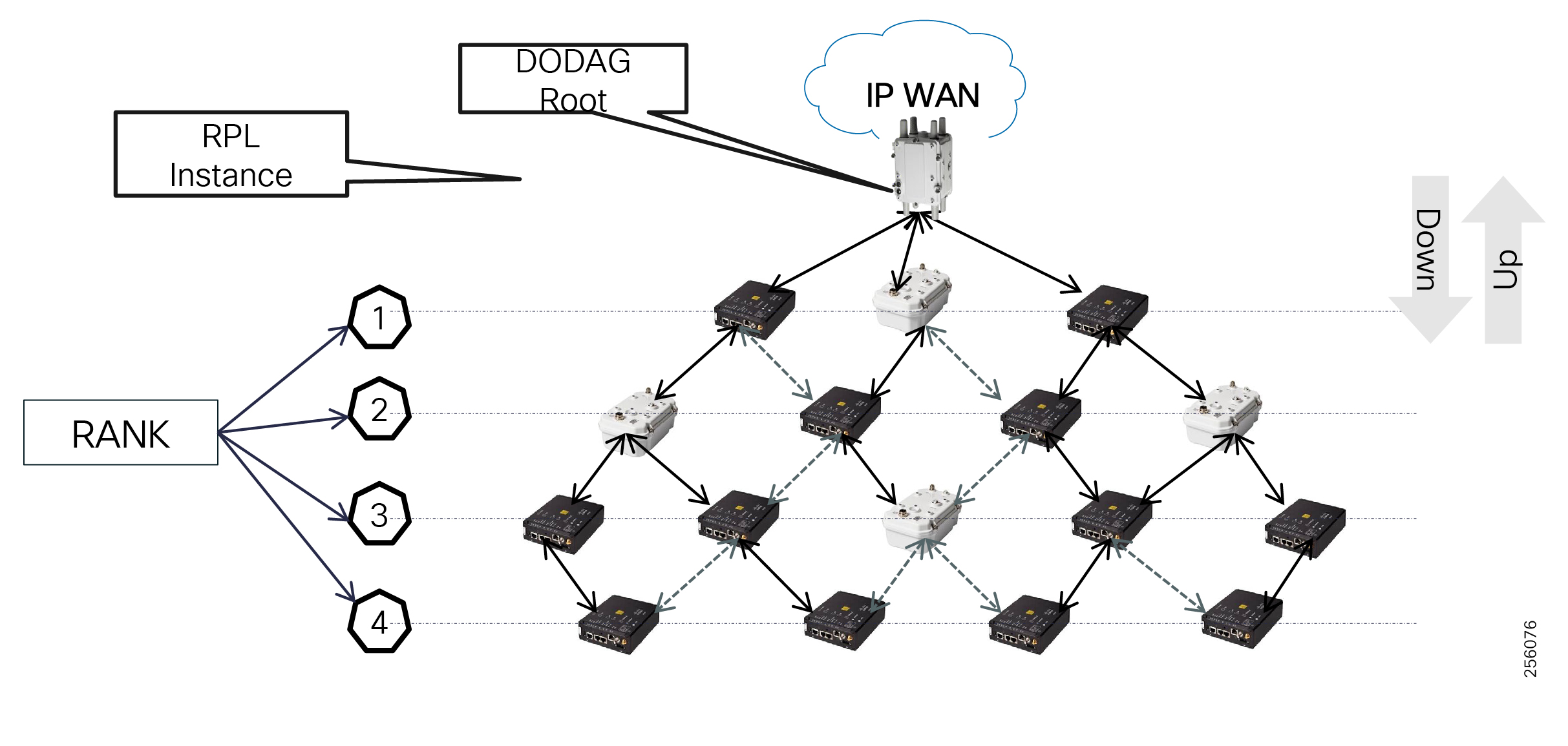
RPL control messages are carried via ICMPv6 message. The following messages are available:
■![]() DAG Information Solicitation (DIS)
DAG Information Solicitation (DIS)
■![]() Destination Advertisement Object (DAO)
Destination Advertisement Object (DAO)
RPL DIO messages are sent for DODAG discovery and maintenance. DIO are link-local multicast packets (all-RPL-nodes multicast address - FF02::1A) according to trickle timers and contain the Routing Mode, Rank information relative to the DODAG root, and the ETX Path. The CGR Rank and ETX Path are set to 0. Trickle timers are an optimized form of controlling the control packets' update frequency by using an adaptive mechanism. DIO messages are sent more frequently when a DAG consistency issue is detected to improve the convergence time. As DAG stabilizes, messages are sent less frequently.
Network administrators can control the regular frequency (in minutes) at which the CGR (root) can solicit DAO destination advertisement messages from the downstream nodes. The shorter the interval, the more up-to-date and accurate the CGR DOGAG topology is. However, this comes at the expense of the grid application available network bandwidth since the RPL control messages utilize more bandwidth. Therefore, a balanced approach should be taken based on the PAN size (number of nodes) and the DA application bandwidth requirements.
Since DIO messages are link-local, each node listens for DIO messages from neighbor nodes. Once a DIO message is received, the node will send ICMPv6 Neighbor Solicitation (NS) unicast messages to evaluate the link quality. Then it will select a preferred parent and alternate or backup parents based on the information within DIO messages and the link quality metric between the node and its candidate parents. Note that to avoid routing loops, a node must select only parents with a lower rank.
Once a node joins a DODAG graph, it will send its DIO messages downstream to other nodes and so forth until all nodes are part of RPL tree. This will result in building the upwards route towards the CGR.
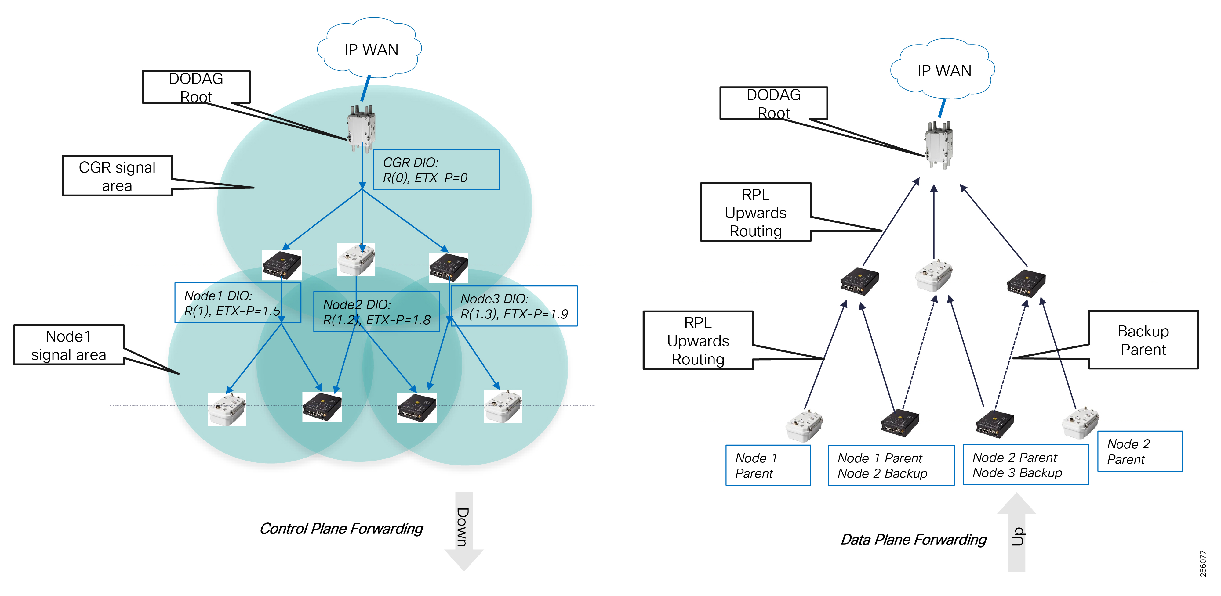
RPL DIS messages are sent by nodes to solicit a DADOG Information Object from another RPL node when the DIO information has expired.
RPL DAO messages are sent by nodes towards the root to inform the CGR of the available destination prefixes and to build the downwards routing from CGR to any DA Gateway in the mesh PAN.
The Cisco solution supports two downwards routing models: Non-Storing Mode and Storing Mode. Nodes learn about the RPL routing mode through the DODAG root DIO message's Mode of Operations (MOP) field.
Non-Storing Mode is used with constrained devices like AMI meters that do not have enough memory to store routing information. Nodes will send DAO messages that includes their parents list directly to the CGR by using double-header encapsulation. The outer header is changes as the packet travels upwards while maintaining the original header intact. CGR receives information from all nodes in the PAN and performs recursive lookup to determine the hop-by-hop path to each destination that will be inserted in the Source Routing Header of a packet. Therefore, in Non-Storing mode, nodes will only have a default route towards the CGR and the CGR will use Source-based Routing (listing all nodes in the path to destination) so that intermediate nodes know to which next hop neighbor they need to forward the packet.
Figure 73 RPL Non-Storing Mode Downwards Routing
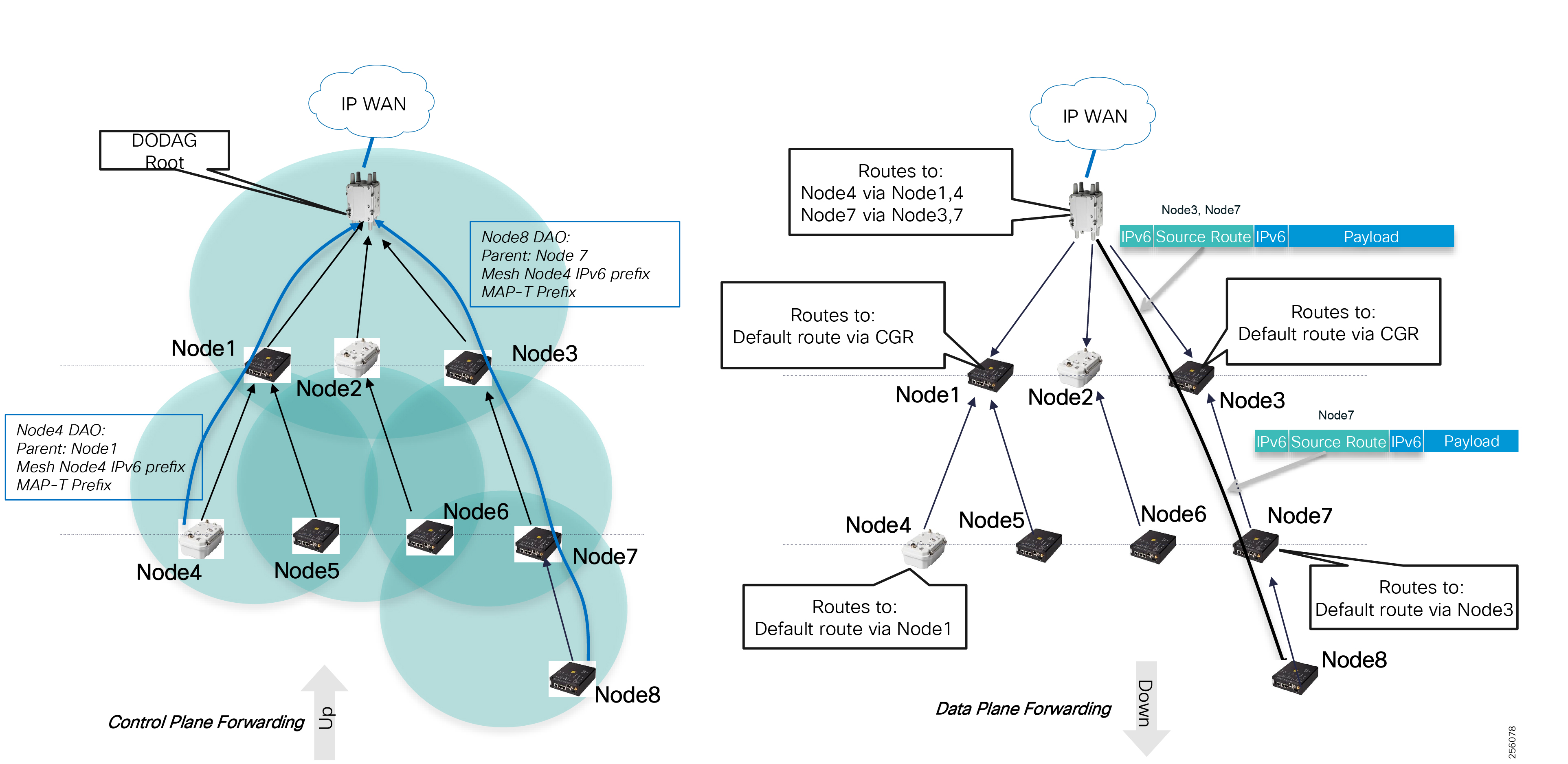
Storing Mode is more appropriate for DA deployments since each parent stores all downstream routes towards their children and children's children.
Note: Non-Storing Mode is the default Downward routing mode; therefore, for DA network deployments, the FAR routes must be configured to use Storing Mode. Further, to enable peer-to-peer communication between the nodes, administrators must enable this functionality since it's disabled by default.
Figure 74 RPL Storing Mode Downwards Routing
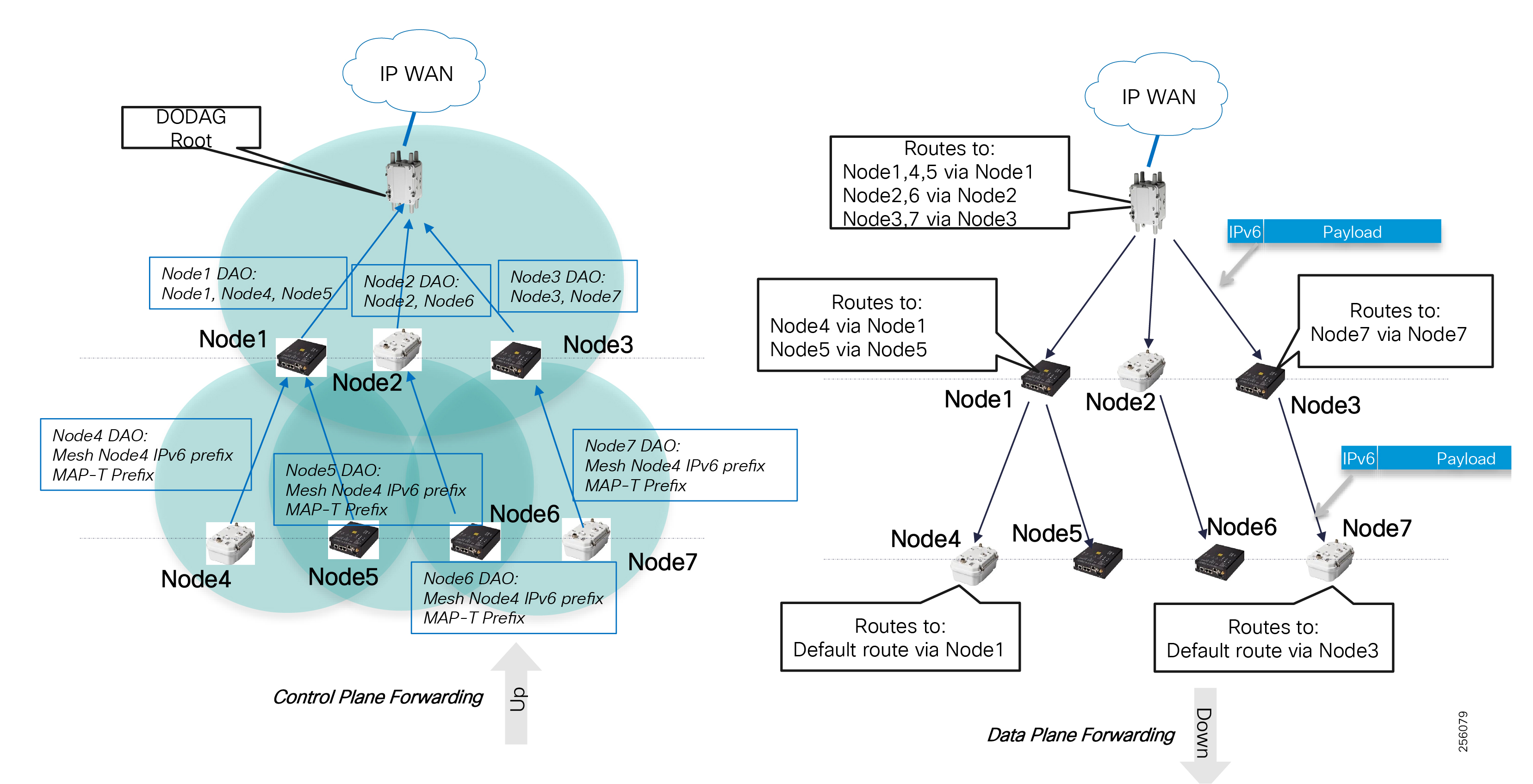
Certain DA FLISR solutions requires peer-to-peer communication between reclosers, so that the end-to-end delay between the grid devices is minimized by reducing the hop count. Traffic does not have to hairpin at the CGR unless the two devices are part of two different branches where the CGR is a common parent.
Note: Since each DA Gateway (IR510/IR530) maintains a routing table, the DA Gateways are limited to 300 routes
Note: Peer-to-peer traffic will always go directly between a source and destination DA Gateway of which they have a parent and child relation, for example, Node7 and Node8. For all other cases, the traffic will flow via the source and destination DA Gateways common parent, for example, Node4 and Node5 via Node1, even if the two nodes can hear each other at Layer 1.
Figure 75 RPL Storing Mode Peer-to-Peer Communication
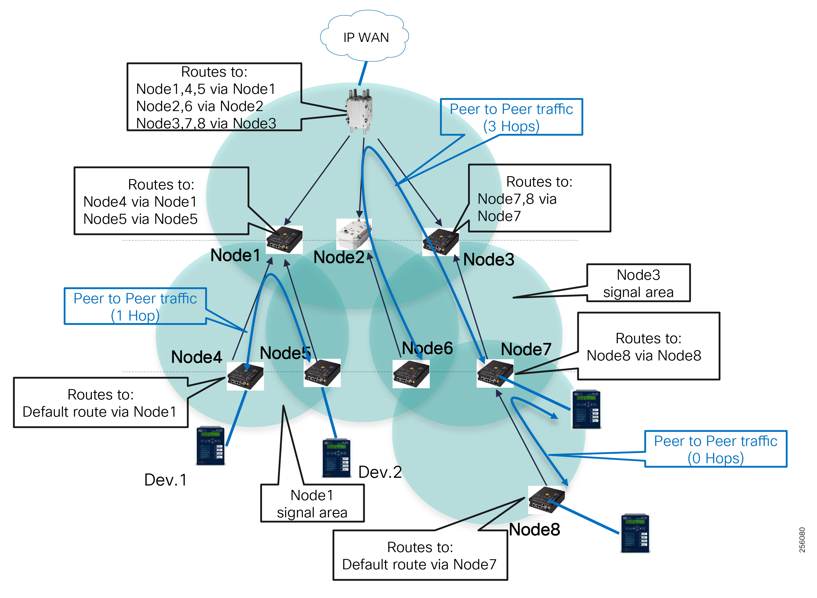
RPL protocols uses control and data messages to categorize each neighbor link quality based on the link RF modulation rate and data rate and packet loss rate over time. This information is reflected in the RPL ETX Link metric, which ties together the RF physical layer to the routing layer. Each node calculates the path cost back to the FAR over each neighbor link and selects the shortest path that indirectly reflects the best reliable path. The value is stored in the ETX Path protocol metric, which is advertised to all the downstream neighbors that take the ETX Path value and add their local ETX link value towards that neighbor to determine their cost to the FAR.
Figure 76 DA Gateway Path Cost Calculation

Figure 76 shows an example of how each node (in this case, Node 13, Node 14 and Node 15) choose their best path towards the CGR when multiple paths are available based on the ETX Path metric. Note that the example uses an ETX Link metric express in multiples of ten for ease of calculation, but, in reality, the values are granular, unit level, and rarely will be the same over two paths.
For scenarios where two paths have the same ETX Path metric, the node will use the parent Received Signal Strength Level (RSSI) as a tiebreaker to select the preferred path.
The next example, Figure 77, shows how a subset of the RPL topology changes when an ETX Link metric increases from 50 to 350 due to packet loss. Node 14 and Node 15 select Node 13 as they parent since the ETX Path to CGR is shorter over that parent.
Figure 77 Path Metric Change due to Link Metric Increased
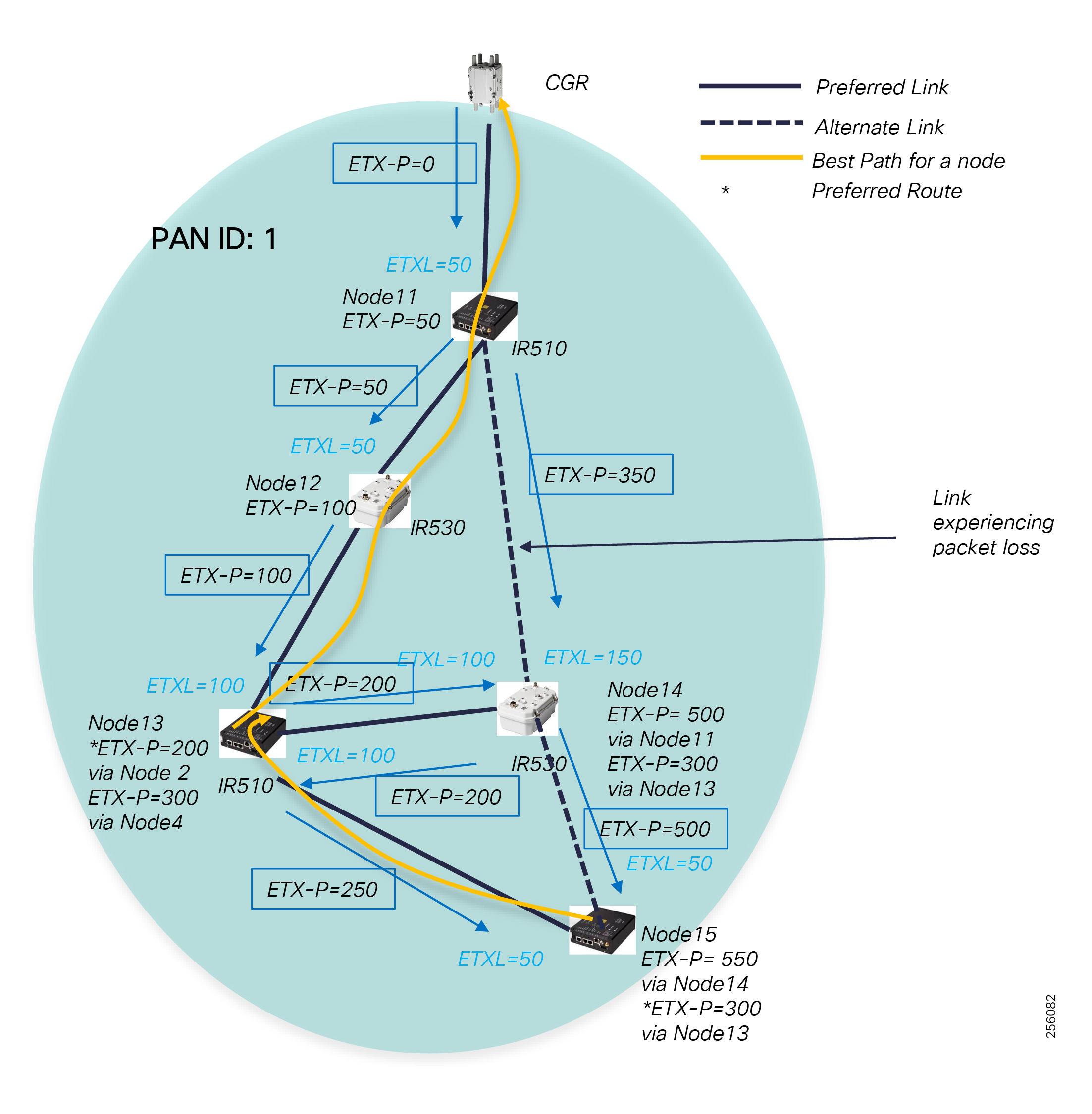
The higher the packet loss rate, the faster a node will switch to an alternate backup parent, but, in general, the goal of the parent selection algorithm is to prevent packet loss, which is more than 10% over the current parent's link. The packet loss rate is an average over time so that the mesh topology stability is maintained and constant flaps are prevented against short temporary changes in the link RF conditions.
A node keeps track of up to four parents and their metrics: one entry for the primary parent, two entries for backup parents, and a fourth entry as a candidate backup in case a backup parent fails, or its metric is not optimal anymore.
Figure 78 DA Gateways Parent Table
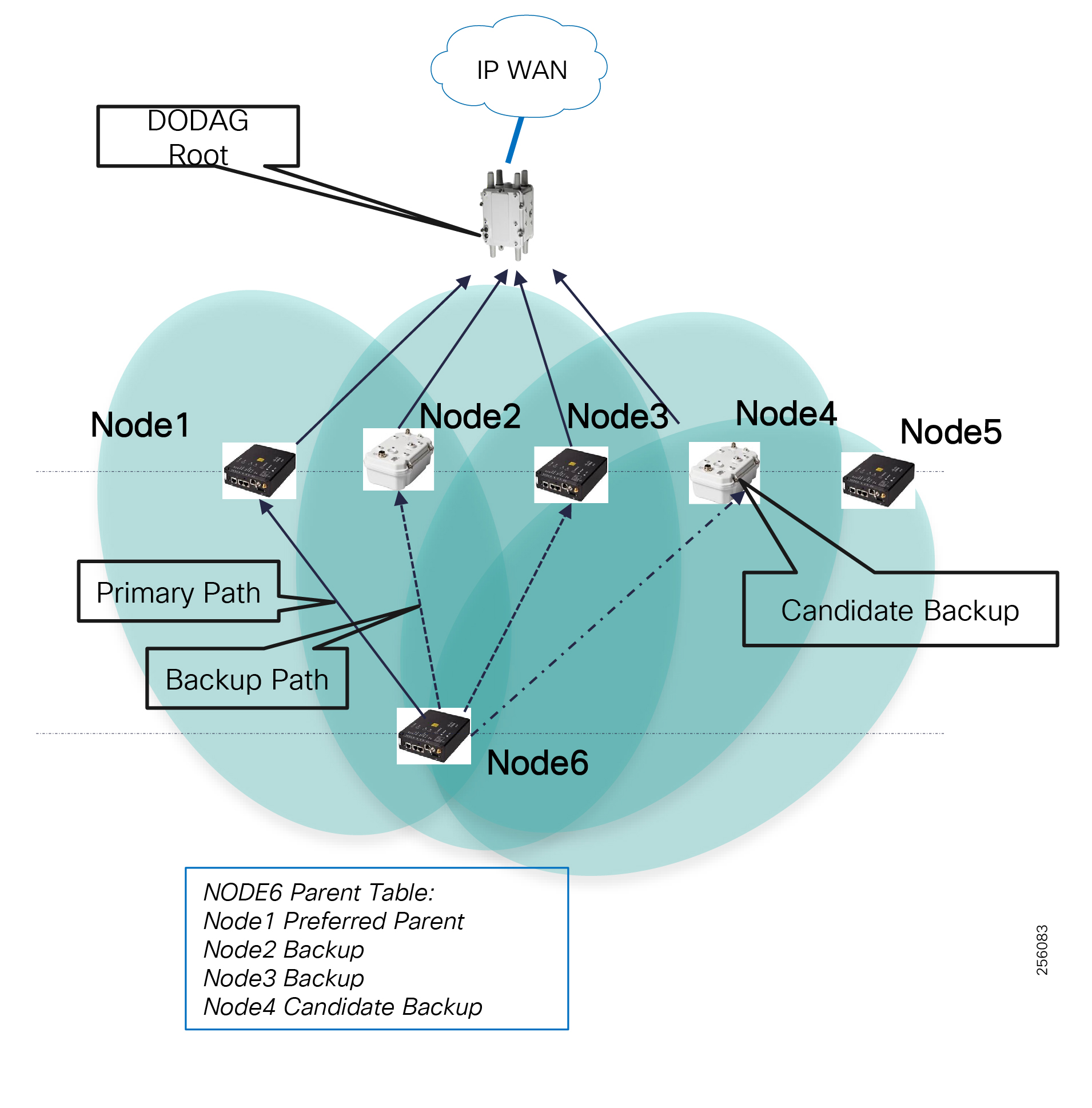
If the primary parent fails, the ETX Link will increase and make the path less preferred and the node will promote a backup parent to a primary parent. Since the node has already computed the ETX Path via the backup node, the next-hop switch will be fast. All the nodes in the Parent Table must have a lower rank than the current node. The Parent table is constantly updated as nodes received DIO messages from all the nearby neighbors.
It is important that customers perform an RF survey and include enough signal degradation margin in the RF link budget to improve network RPL stability.
In addition, it is important to plan the network in such a way that a node has at least two parents to choose from that will increase the network availability.
The FAR router WPAN Global IPv6 prefix for the mesh is inserted in the router RIB table as a connected prefix with an Administrative Distance (AD) of 0 and metric of 0. DA Gateway's MAP-T IPv6 Prefixes will show in the CGR routing table as host routes (/128) representing each DA Gateway's MAP-T BMR IPv6 address. If the Ethernet interface is configured with an IPv6 prefix, that prefix will also exist in the CGR RIB table. DA Gateways prefixes are inserted by RPL in the CGR routing table as connected routes with an AD of 0 with a metric of 19 on the HA Primary CGR router and with a metric of 29 on the Back-up HA CGR router.
|
|
|
|
|
|
|
Administrators will need to redistribute the routes (connected and interface WPAN) in the WAN layer by using the FlexVPN IKEv2 Dynamic Routing Updates feature or into a dynamic routing protocol (such as BGP and EIGRP) that runs within the FlexVPN tunnel. For High Availability designs with two tunnels (primary and back), administrators will also need to ensure that the backup tunnel metric has a high cost than the primary tunnel.
WAN Routing
In the WAN layer with a FlexVPN design, customers will configure routing at the transport layer (outer tunnel) as well as the overlay layer (inner tunnel). At the transport layer for Private WAN, the routing protocol is a customer choice in case of dark fiber or it depends on the Service Provider peering requirements of either static routing or dynamic routing, typically BGP.
For the VPN overlay, layer customers can choose to use between an IKEv2 Dynamic Routing Update (DRU) feature and a dynamic routing protocol based on the number of DA applications, DA deployment size, WAN size, WAN transport services, and specific convergence requirements for HA deployments. The IKEv2 DRU, when compared with traditional dynamic routing protocols, is lighter in control plane usage and therefore better fitted for Cellular WAN connectivity where the monthly cellular data plan has a limit.
|
|
|
|
|
|
|
|
|
Note: The performance numbers should be used as reference. Since the maximum limit heavily depends on how many services ran on the HER and the throughput rate, customers should do the initial planning based on the recommended scale values and should work with the local Cisco account team for more up-to-date validated scalability numbers.
Note: IKEv2 DRU in the future will support Virtual Routing and Forwarding (VRF) as well as a large number of spokes per hub ratio since today FlexVPN supports up to 10,000 spoke tunnels on certain Cisco router platforms.
For Mesh deployments that support DA Gateway migration between different PAN IDs (Inter-PAN), the WAN must support dynamic route advertisement of the DA Gateway MAP-T and Ethernet IPv6 prefix over the WAN so that traffic from the Control Center can be routed to the proper FAR device.
The Resilient Mesh network prefixes and the Control Center prefixes should only be advertised into the Overlay routing protocol that runs over the tunnel interfaces. This will hide the DA network addresses from the transport layer or Service Provider routing domain.
When running one or more dynamic routing protocols between the Transport and Overlay layers, make sure that the transport network prefixes are not learned via the overlay routing protocols and are filtered to avoid tunnel failure due to recursive lookup scenario.
To scale and support large number of FAR devices, the network administrator must implement routing optimization best practices for each routing protocol. For example, Route Summarization should be configured on the FlexVPN Hub routers (HERs) to only advertise a summary route of all the Control Center prefixes. Advertising a default route can also be an option, but would attract any unknown traffic from the FAR devices towards the Control Center, which can use unnecessary WAN bandwidth or become a security concern if a remote location is compromised.
For all the remote traffic to go to the Primary Control Center, the summary route or routes from the Back-up Control Center should be advertised with a higher cost.
The FAR devices should be configured to summarize all the local substation prefixes and the mesh prefixes to reduce the FlexVPN Hub routing table since it aggregates a large number of FAR devices. This will also prevent any route updates in the substation or mesh to be propagated to the Control Center, therefore minimizing the routing control plane utilization. The only time DA Gateways host routes that will be advertised as specific routes over the WAN is when a DA Gateway performs an Inter-PAN migration, assuming there is Layer 1 connectivity for the device to attach himself to another substation Mesh network. The MAP-T and Ethernet IPv6 prefix will have to be advertised as specific routes; the default behavior is to allow a grid device attached to the DA Gateway to maintain its configured IP address and that the traffic for it will be routed to the new FAR device and mesh network.
Figure 79 WAN Routing Summarization Boundaries
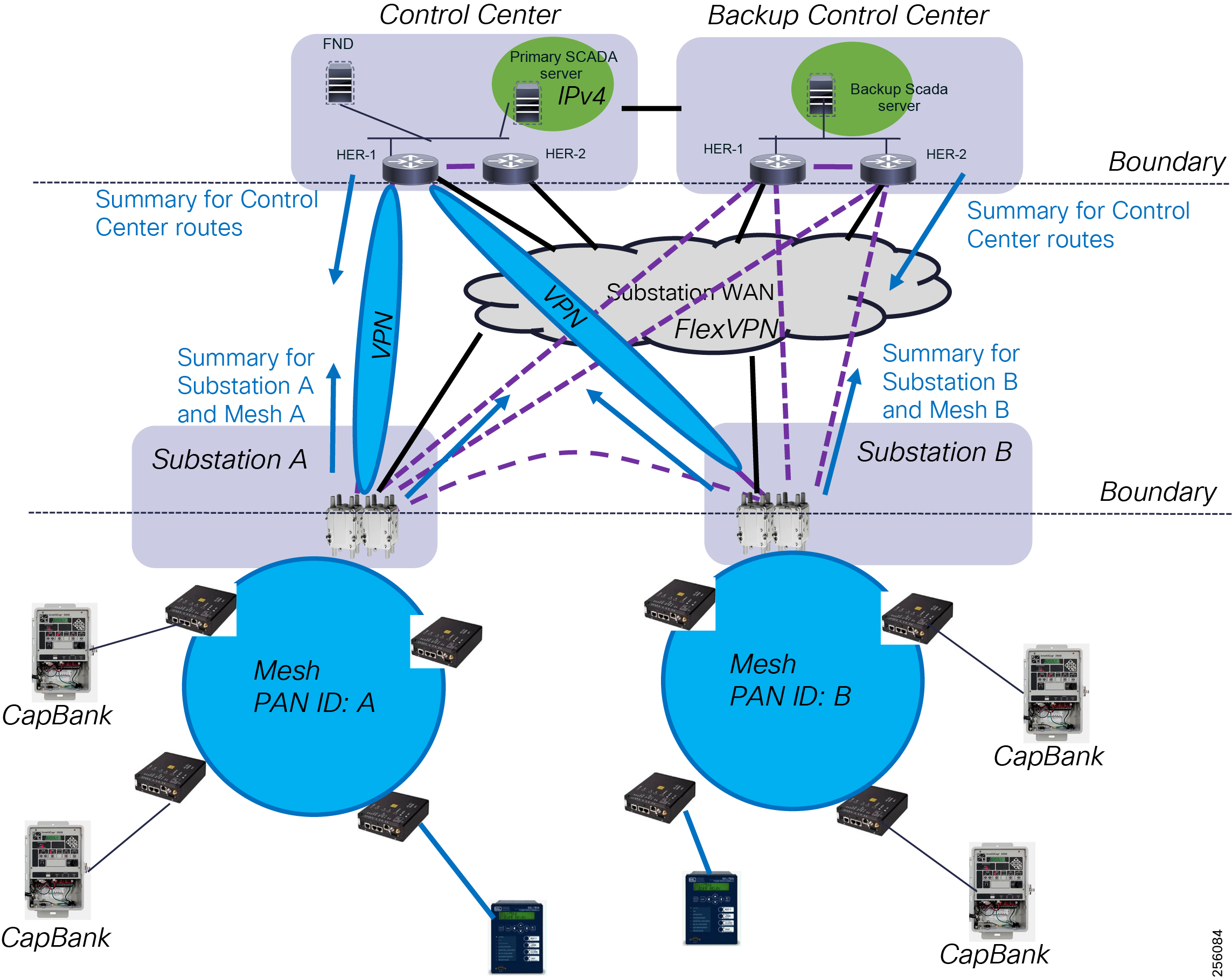
Ideally, the two Control Centers should be interconnected by a dedicated link so that if the Primary Control Center primary WAN link fails, the FAN traffic can be sent to the Back-up Control Center and through the dedicated link back to the Primary Control Center. This will avoid the Grid Systems and FAN Management systems from having to perform a failover to the Back-up Control Center.
Control Center Routing
Customers can choose to use the same routing protocol in the Control Center over the Overlay VPN network as long it scales and meets the DA deployment requirements.
However, in general, it is best to create different routing failure domains so that if a major network outage occurs due to human errors, the failure won't affect other parts of the network. In that case, each site will run an Interior Gateway Protocol (IGP) routing protocol within the site. Each site will be also configured with its own Border Gateway Protocol (BGP) AS number and an external BGP (eBGP) peering will be configured between each site over the FlexVPN networks since BGP has better routing policy control capabilities such as for route filtering, peer and route security and route dampening.
The Control Center WAN router will run both IGP and BGP routing protocols and would advertise the local site IGP prefixes into BGP so that remote sites would know how to route to these prefixes. The remote prefixes learned by the WAN routers via BGP would advertise these routes into the IGP protocols without the need for redistribution.
Network Services
Quality of Service
Following the IETF Differentiated Service model (RFC 2474), the FAN solution will deliver a particular kind of service based on the QoS specified for each packet. This specification can be made in different ways, one of them being the IP Precedence bit settings in IP packets or source and destination addresses. The QoS specification can be used to classify, mark, shape, and police traffic, and to perform intelligent queuing.
QoS refers to the ability of the network to provide priority service to selected network traffic, thus increasing predictability by:
■![]() Supporting dedicated bandwidth
Supporting dedicated bandwidth
■![]() Reducing loss characteristics
Reducing loss characteristics
■![]() Avoiding and managing network congestion especially with multi-services traffic
Avoiding and managing network congestion especially with multi-services traffic
■![]() Setting traffic priorities across the network - multi-services capabilities
Setting traffic priorities across the network - multi-services capabilities
QoS is a key feature when designing multi-services Field Area Networks, as the need exists to differentiate and prioritize between traffic from different DA systems (such as FLISR and Volt/VAR) and network management use cases, for example communication equipment upgrades or new Edge Compute applications. Estimated transport losses, delay, and jitter introduced by networking devices must be considered when forwarding sensitive data, particularly when a WAN backhaul link offers constrained bandwidth. In the case of dual-WAN interfaces with different bandwidth capabilities (such as Ethernet and cellular for backup), QoS policies must be applied to prioritize the traffic allowed to flow over these limited bandwidth links in order to determine which traffic can be dropped.
QoS also needs to be considered over the substation WAN and Control Center infrastructure layers, especially during network congestion. Typically, the WAN and CC communication infrastructure does not have the mesh hardware constraint for low power consumption and supports more advanced QoS settings. Therefore, mapping of the QoS policies between the different FAN architecture layers is critical.
Figure 80 End-to-End QoS Architecture
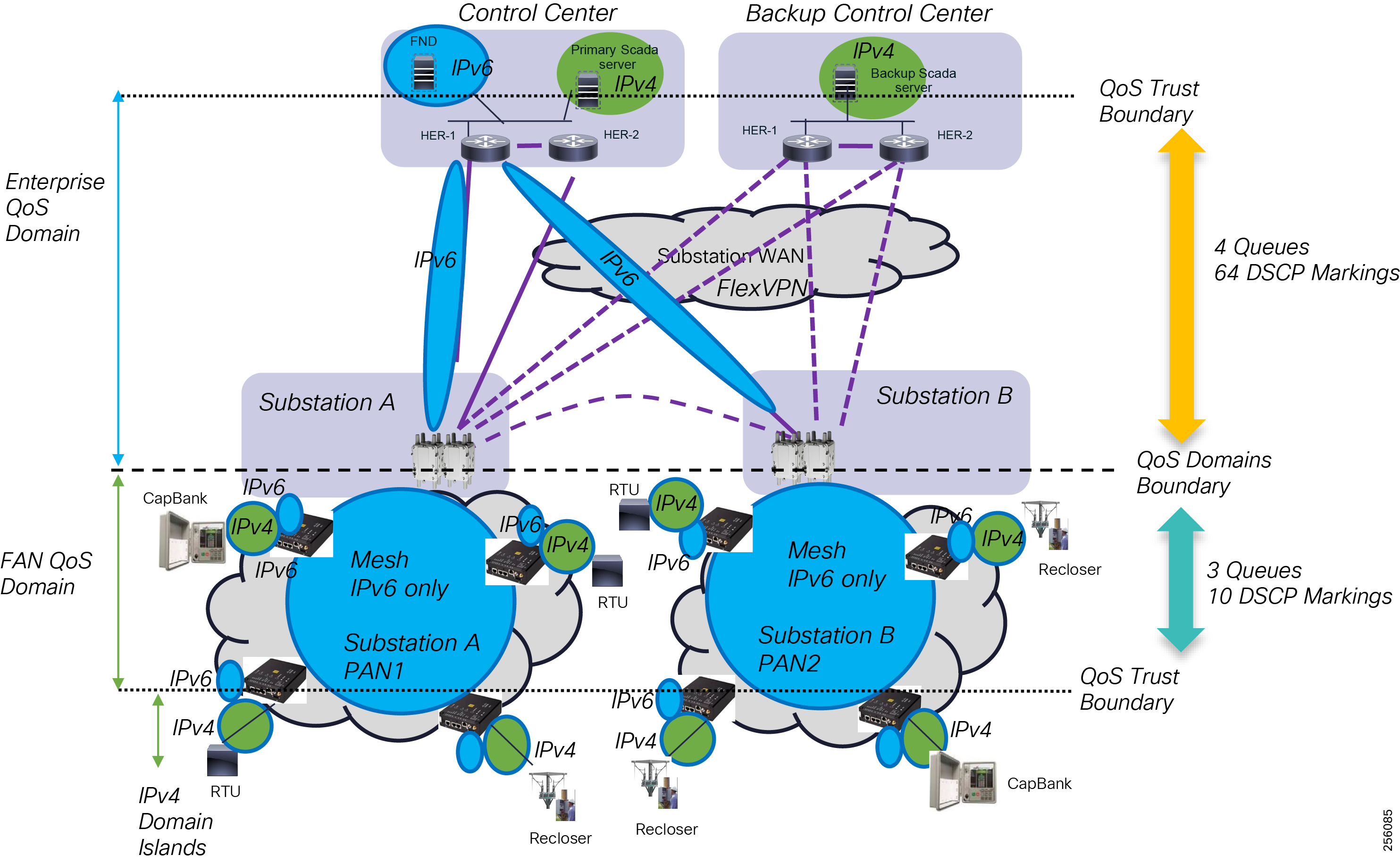
FAN Infrastructure Layer
The FAR performs QoS actions on Layer 3 interfaces, as documented in the CGR 1000 QoS configuration manual. The sequencing of QoS actions on egress traffic is as follows:
The general CG-Mesh QoS guidelines are:
■![]() All traffic should have a Differentiated Services Code Point (DSCP) QoS value set
All traffic should have a Differentiated Services Code Point (DSCP) QoS value set
■![]() Traffic without a DSCP will be put in the Low queue
Traffic without a DSCP will be put in the Low queue
■![]() The default queue for most traffic should be the Normal queue
The default queue for most traffic should be the Normal queue
■![]() Traffic placed in Medium or High queue should be justified.
Traffic placed in Medium or High queue should be justified.
■![]() It must be recognized that traffic in a higher queue can cause traffic in lower queues to drop.
It must be recognized that traffic in a higher queue can cause traffic in lower queues to drop.
The Resilient Mesh devices use Priority Queuing with four types of egress queues (Q1-Q4) using Strict Priority scheduling. The Q4 queue, which is reserved and cannot be configured, is used for the mesh control plane traffic such as Layer 3 RPL protocol packets, and neighbor discovery.
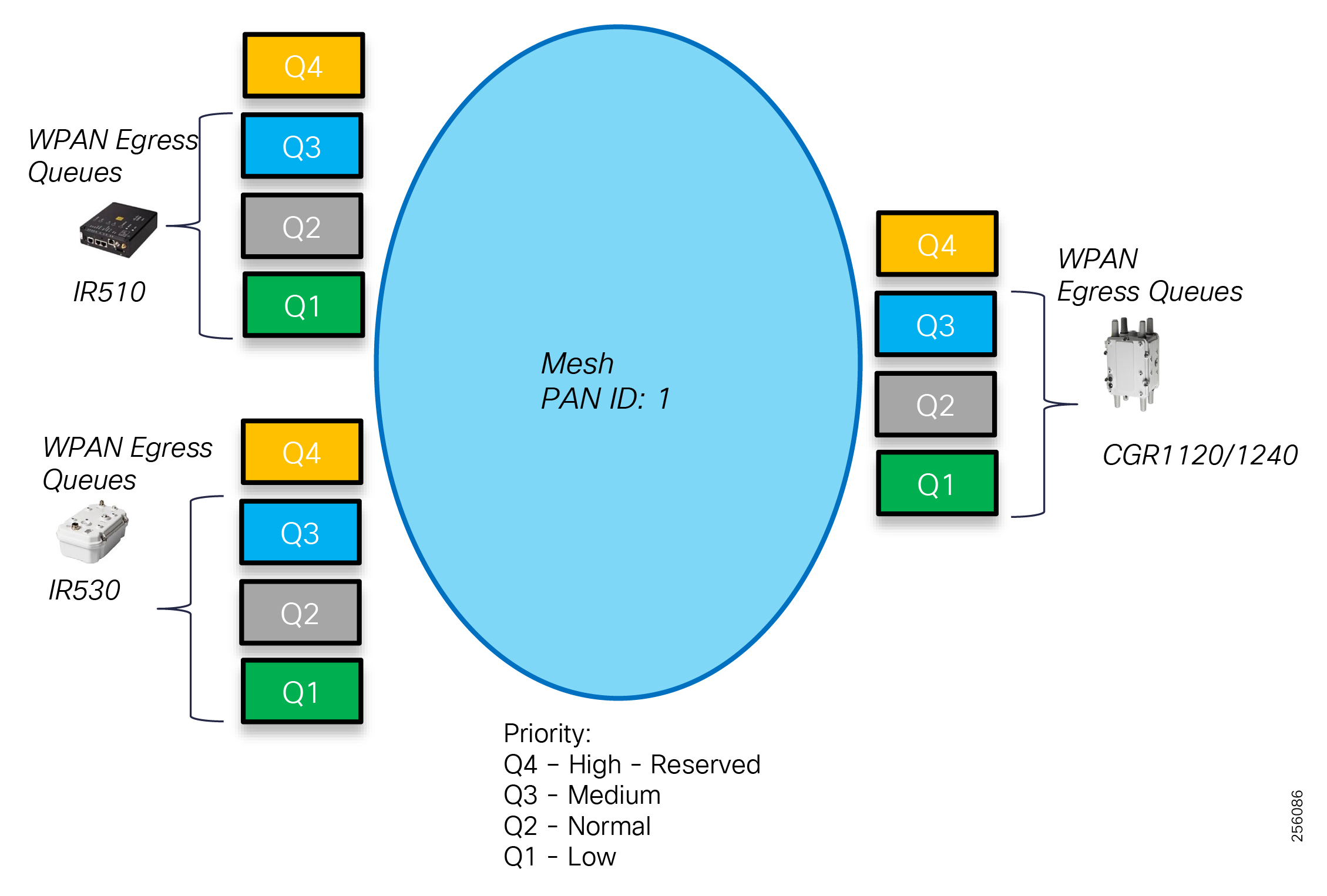
Administrators can classify traffic based on traffic criticality: low, normal, and medium. The traffic is automatically mapped to low priority traffic to Q1 queue, normal priority traffic to Q2, and medium priority traffic to Q3.
Note: Q4 is reserved and administrators cannot configure it.
|
|
|
|
|
|
|
|
Note: Software version 6.0 only supports three types of markings: Low - DSCP 0, Normal - AF11/DSCP 10, Medium - AF21/DSCP18. The next software release, Mesh 6.1 will support all the 10 DSCP markings listed in Table 46.
■![]() https://www.cisco.com/c/en/us/td/docs/routers/connectedgrid/cgr1000/ios/modules/wpan_cgmesh/b_wpan_cgmesh_IOS_cfg/wpan_cgmesg_IOS_cfg.html
https://www.cisco.com/c/en/us/td/docs/routers/connectedgrid/cgr1000/ios/modules/wpan_cgmesh/b_wpan_cgmesh_IOS_cfg/wpan_cgmesg_IOS_cfg.html
Note: For the remaining sections, the diagrams will use the convention shown in Figure 82 to capture the Layer 3 packet QoS marking. IEEE 802.15.4g/e does not specify a Layer 2 frame QoS field for unslotted CSMA.
The Queue scheduler will always empty the higher priority queues ahead of the low priority queue. For example, before a device can empty the Q2 packets, the Q4 and Q3 queues must be empty. The scheduler uses a round-robin sequence that always starts at the higher priority queue.
The three type of traffic marking can be done at the following locations:
■![]() Inbound Ethernet physical port (Eth0). All incoming packets will be mark with the same traffic class.
Inbound Ethernet physical port (Eth0). All incoming packets will be mark with the same traffic class.
■![]() Inbound virtual IOx switch, per source IPv4 address, under a device DSCP profile, for Edge Compute applications
Inbound virtual IOx switch, per source IPv4 address, under a device DSCP profile, for Edge Compute applications
■![]() Per serial interface, under Serial interface profile, for Raw Socket scenarios
Per serial interface, under Serial interface profile, for Raw Socket scenarios
Figure 83 Ethernet Port Marking
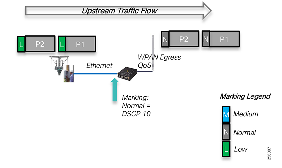
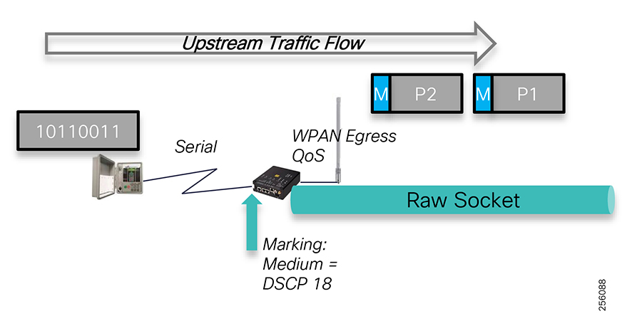
Figure 85 Edge Compute Application Markings
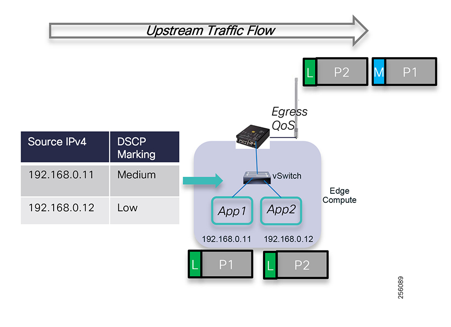
Packets that are already marked by end devices or Edge Compute application will be overwritten with DSCP value 0 or remarked with the QoS class assigned (Low, Normal, and Medium).
Figure 86 is an example of how QoS works between two devices. Higher priority packets, Medium classification will be sent before Lower priority packets, Normal or Low. The same logic works for upstream flows as well.
Figure 86 QoS Queuing and Scheduling
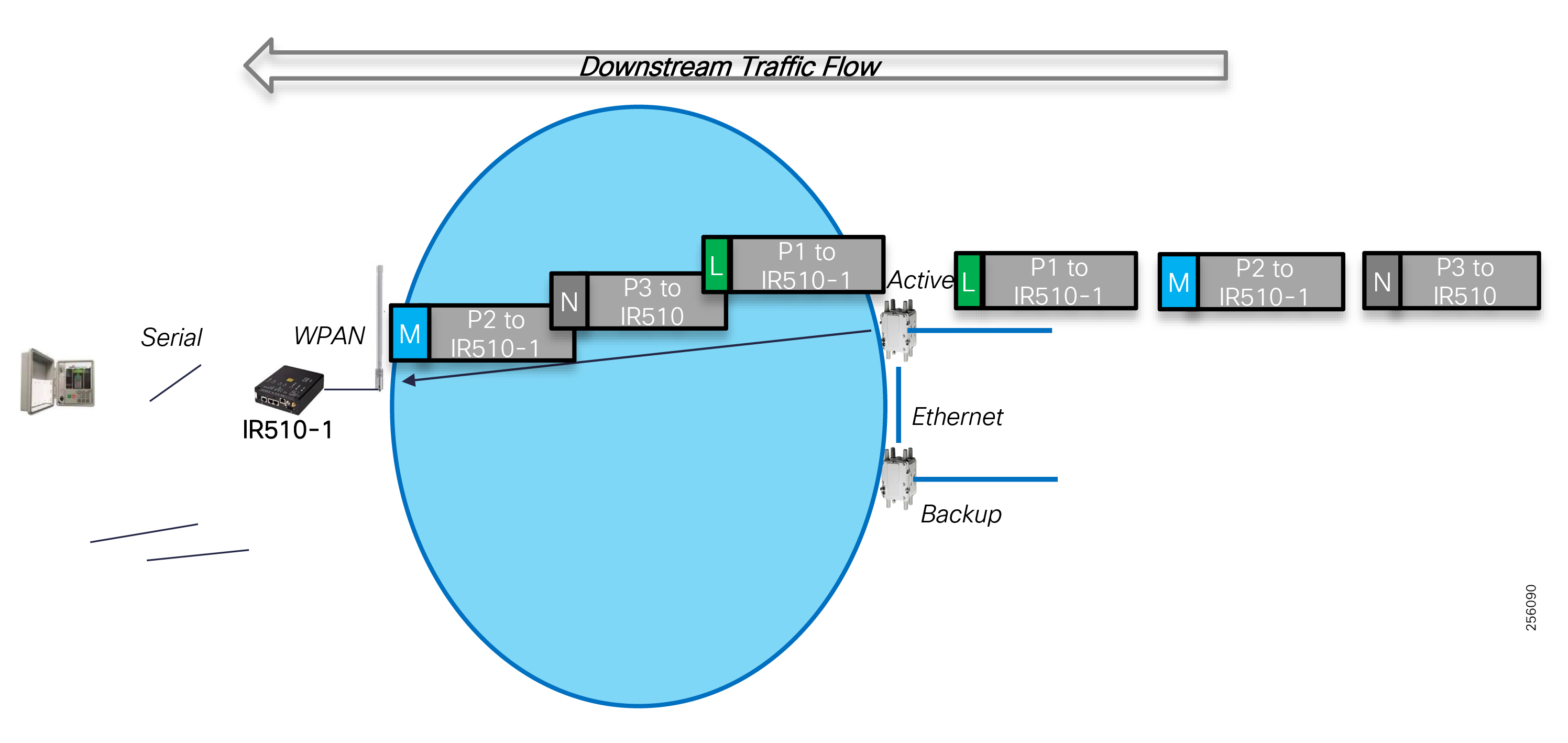
When multiple DA gateways want to send traffic to their parent, there are certain scenarios when collision can occur, or when Mesh nodes are further apart where the Clear Channel Assessment (CCA) can't operate and packet retransmission will take place. The Resilient Mesh software has implemented an advanced QoS mechanism to dynamically adjust the back-off timer for collision or retransmission that each node uses based on the packet QoS marking. Higher priority packets will have a shorter back-off interface; therefore, they will be sent before lower priority packets.
Figure 87 Advanced MAC Layer QoS
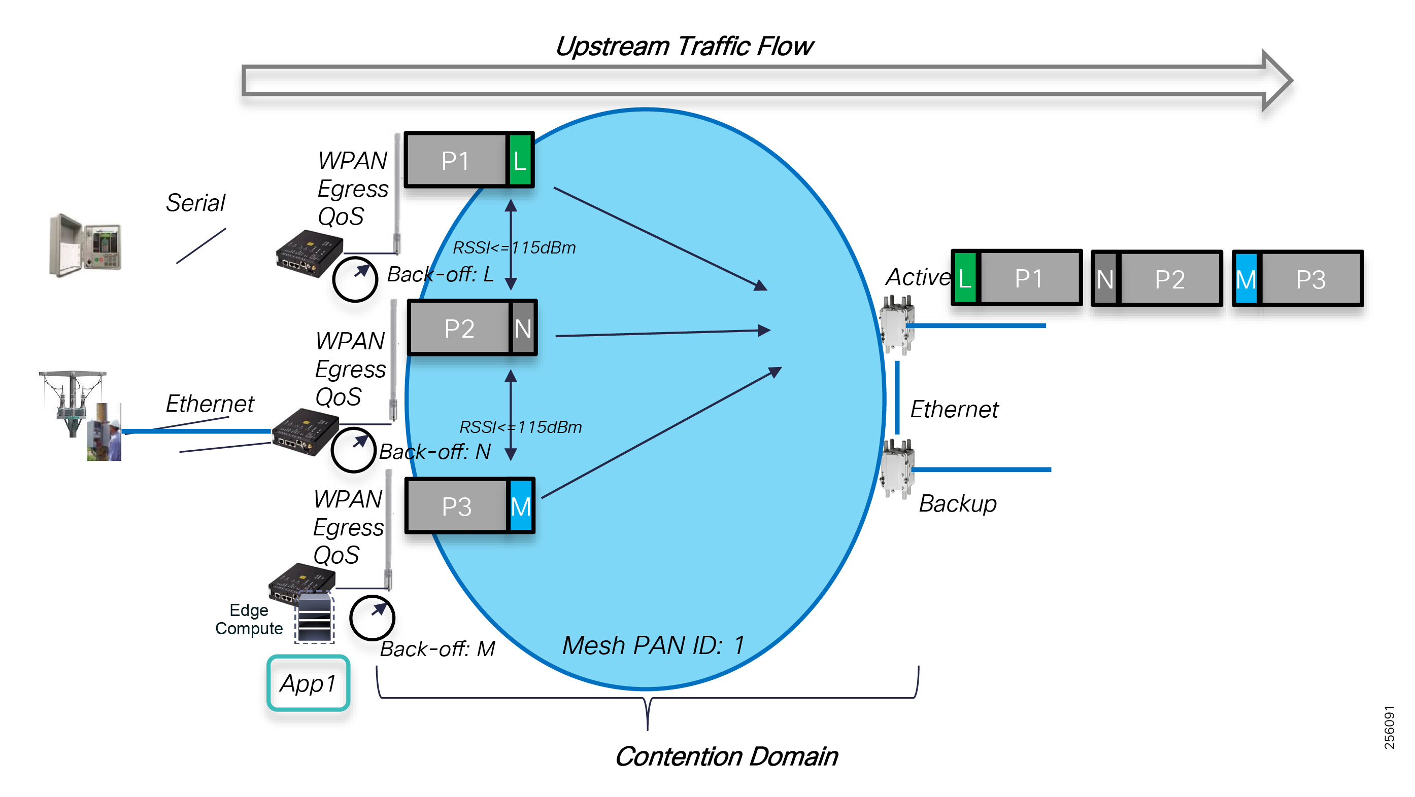
In Figure 87, each node is sent a packet with different QoS markings towards their common parent. When a collision occurs, each node will use a back-off timer value that is directly related to the packet QoS markings. Packets with High Priority classification (Medium) will experience lower back-off time than Normal or Low packets; therefore, they will arrive at the parent node ahead of the other packets. If retransmission takes place, then packets with higher priority will have a shorter retransmission delay than lower priority packets, increasing the probability of being delivered ahead of the lower QoS classes.
Cisco recommends that critical FAN DA applications like FLISR should be marked with Medium priority whereas Volt/VAR or other application should be marked as Normal.
|
|
|
|
|
|
||
|
|
||
|
|
||
|
|
WAN Infrastructure Layer
Cisco FAR router supports two QoS models: one model for the FAN Mesh that runs on the WPAN module that has been described above and another for WAN and Control Center devices that run Cisco's full class IOS or IOS-XE operating system. The CGR routers are the boundary line between the two domains. There is a mismatch on the number of DSCP values that each domain supports; therefore, network administrators might need to aggregate the extra WAN markings into the Mesh markings when number of grid application exceeds the Mesh QoS markings.
The CGR IOS's modular QoS CLI (MQC) also uses Priority Queuing and supports four queues: Q1 to Q4, where Q1 has the highest priority with a Strict Priority schedule. CGR IOS supports 64 DSCP values and allows network administrators to use class-maps, policy-map and service-policy configuration to apply QoS markings to each grid application type and also assign the packets to the proper interface queue for proper service level.
In general, the packets arriving to the FAR router should already be marked and should only be remarked if they are out of policy.
Figure 88 FAR QoS Queuing Architecture
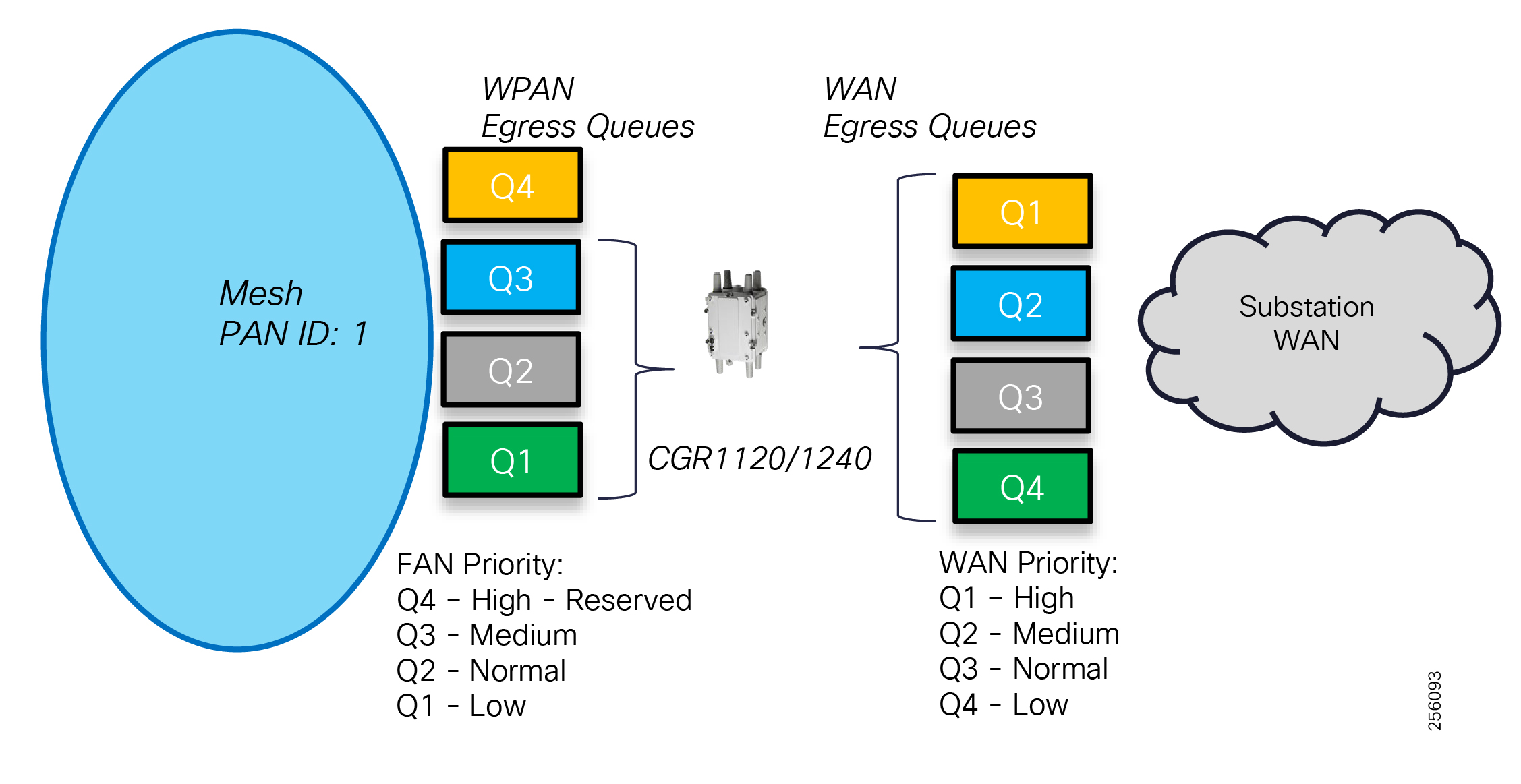
Since the WAN uses a VPN overlay architecture, the marked packets (Inbound QoS) from the Mesh destined to the Control Center must be preserved as it becomes encapsulated with new tunnel IP headers (Outbound QoS).
Cisco IOS supports QoS per Tunnel interface and the Inbound QoS DSCP values will be copied to the Outbound QoS DSCP field, which is important if the customer WAN supports QoS.
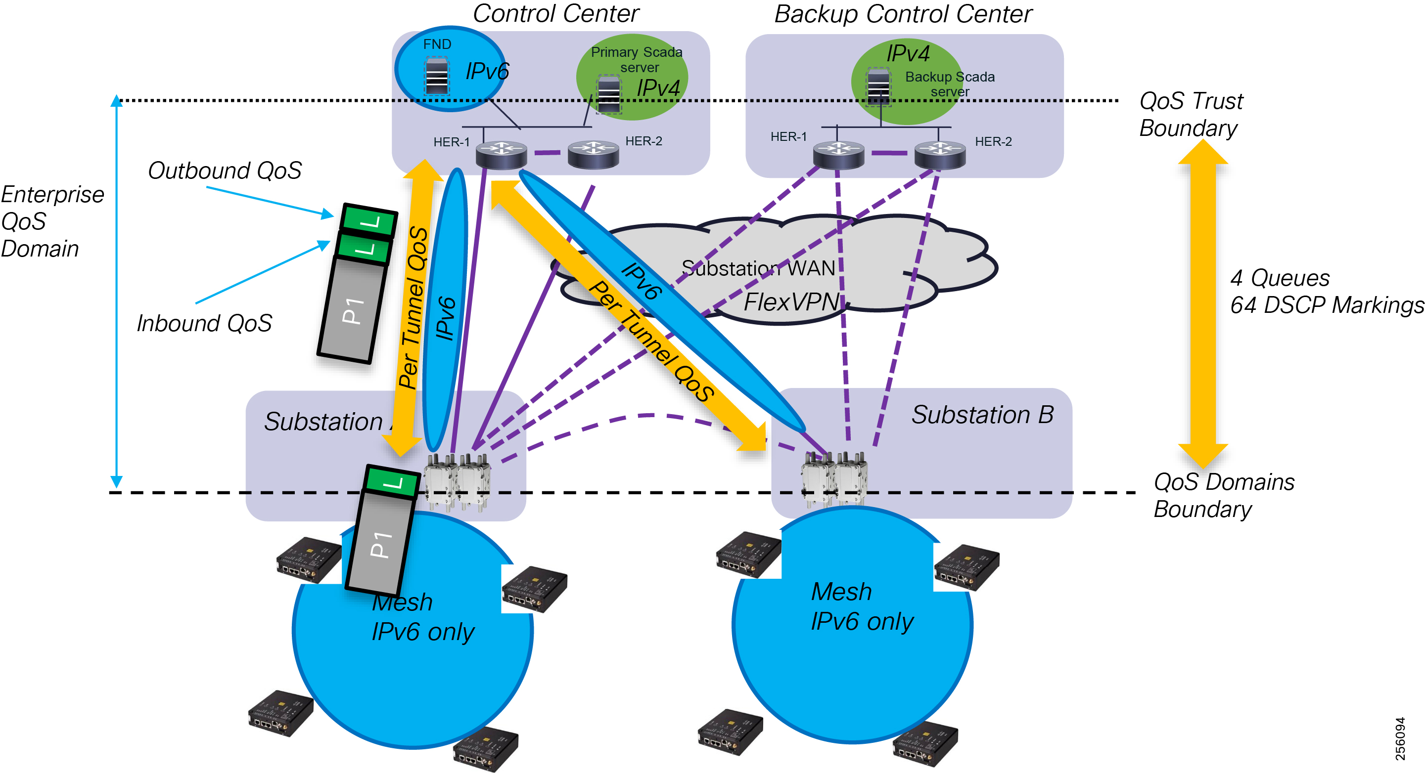
For additional information regarding the CGR QoS feature, please consult the Cisco CGR 1000 Configuration Guide by using the link below.
■![]() https://www.cisco.com/c/en/us/td/docs/routers/connectedgrid/cgr1000/1_0/software/configuration/guide/qos/cgr1000_Book/qos_stats_cgr1000.html
https://www.cisco.com/c/en/us/td/docs/routers/connectedgrid/cgr1000/1_0/software/configuration/guide/qos/cgr1000_Book/qos_stats_cgr1000.html
The Distribution Automation - Secondary Substation Design Guide offers additional details about FlexVPN QoS design considerations:
■![]() https://www.cisco.com/c/en/us/td/docs/solutions/Verticals/Distributed-Automation/Secondary-Substation/DG/DA-SS-DG/DA-SS-DG-doc.html
https://www.cisco.com/c/en/us/td/docs/solutions/Verticals/Distributed-Automation/Secondary-Substation/DG/DA-SS-DG/DA-SS-DG-doc.html
Headend Infrastructure Layer
In the Control Center, customers can choose from a variety of network infrastructure platforms, either IoT or Enterprise based on their specific requirements. Each platform has its own unique QoS capabilities, which are well described in the product or solution configuration guides available at Cisco.com.
The QoS Trust boundary lays on the headend switching infrastructure; therefore, packet classification and marking should be performed as close as possible to the Grid Application servers. Once traffic has been classified, the transient network devices trust and honor the QoS service level assign to each application.
The Control Center WAN blocks the VPN aggregation devices. HERs will also need to be configured to support QoS over the VPN tunnel interfaces.
In general, the remote substations have bandwidth mismatch between the physical interface speed and the WAN service provision for the substation connectivity. This is true especially for Cisco Off-Net Substation WAN designs where customers use a Service Provider service like the Managed MPLS Layer 3 service.
Figure 90 Bandwidth Asymmetry between Central and Remote Substations
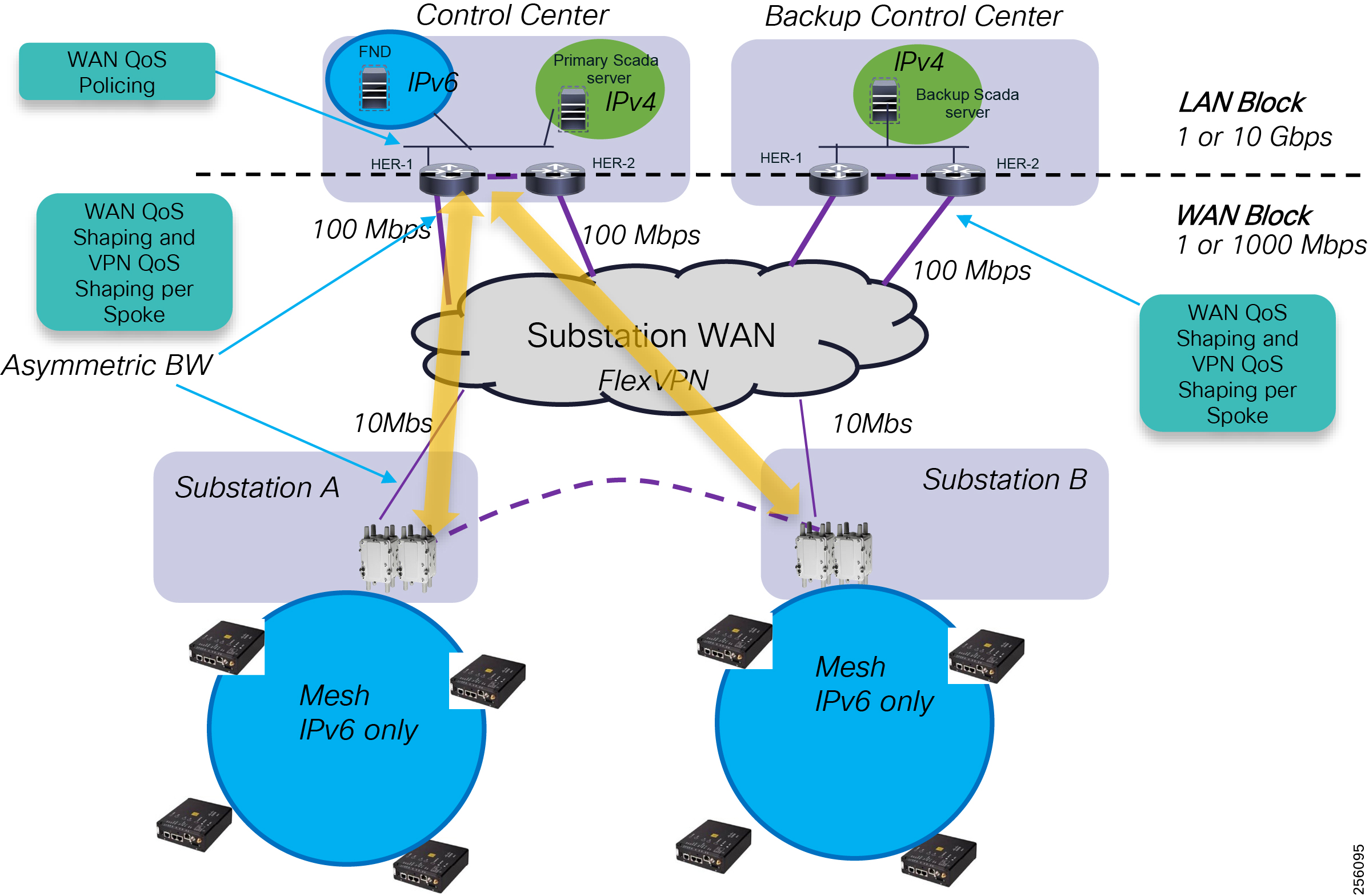
–![]() Network administrators should configure the HER devices with an egress QoS policy to shape traffic for the proper WAN service speed rather than the router physical WAN speed interface if the two don't match.
Network administrators should configure the HER devices with an egress QoS policy to shape traffic for the proper WAN service speed rather than the router physical WAN speed interface if the two don't match.
–![]() Since all the traffic from the field devices is destined to the Control Centers, the WAN services will be provisioned with higher service speed than the remote substation or the field locations where the CGR routers will be deployed. To prevent traffic from Control Center systems from oversubscribing the substation WAN link, network administrators should configure on the HERs a per-Spoke QoS policy based on the remote spoke WAN service speed. To accommodate for burst traffic, the QoS policy should shape temporary busty traffic and police traffic that's outside of a typical substation QoS traffic profile.
Since all the traffic from the field devices is destined to the Control Centers, the WAN services will be provisioned with higher service speed than the remote substation or the field locations where the CGR routers will be deployed. To prevent traffic from Control Center systems from oversubscribing the substation WAN link, network administrators should configure on the HERs a per-Spoke QoS policy based on the remote spoke WAN service speed. To accommodate for burst traffic, the QoS policy should shape temporary busty traffic and police traffic that's outside of a typical substation QoS traffic profile.
Note: The Cisco FAN Headend Implementation Guide offers additional details about the Control Center design considerations.
■![]() https://salesconnect.cisco.com/open.html?c=db570d3f-3212-4659-a306-5f65aeab862b
https://salesconnect.cisco.com/open.html?c=db570d3f-3212-4659-a306-5f65aeab862b
Network Time Services
Certain services running on the FAN require accurate time synchronization between the network elements. Many of these applications process a time-ordered sequence of events; therefore, the events must be time stamped to a level of precision such that individual events can be distinguished from one another and correctly ordered. A Network Time Protocol (NTP) version 4 server running over IPv4 and IPv6 network layer can act as a Stratum 1 timing source for the network.
Over the FAN, the NTP might deliver accuracies of 10 to 100 milliseconds, depending on the characteristics of the synchronization source and network paths in the WAN.
Some of the applications that require time stamping or precise synchronization are:
■![]() Validation of X.509 certificates used for device authentication, specifically to ensure that the certificates are not expired
Validation of X.509 certificates used for device authentication, specifically to ensure that the certificates are not expired
■![]() Time stamps for meter readings, asynchronous notifications from meters, log entries, and so on
Time stamps for meter readings, asynchronous notifications from meters, log entries, and so on
■![]() Dying Gasp feature used for device outage notifications
Dying Gasp feature used for device outage notifications
The Cisco Headend infrastructure that includes FND, RA, TPS, NPS, and PKI Servers should have its clock synchronized to the same source: ideally a NTP server that receives time from the Internet or is connected to a GPS appliance. The FAR routers can be configured to receive time information via NTPv4 from HER or from the local GPS interface. FAR routers distribute their time information to other mesh nodes via Sync Beacon messages. IR510 can also receive time information from its local GPS interface.
Network Security
The Cisco Resilient Mesh solution for FAN DA has the best industry security practices built in from physical security features to application and firmware integrity. All the solution's security protocols are open standards based.
Figure 91 FAN Security Overview
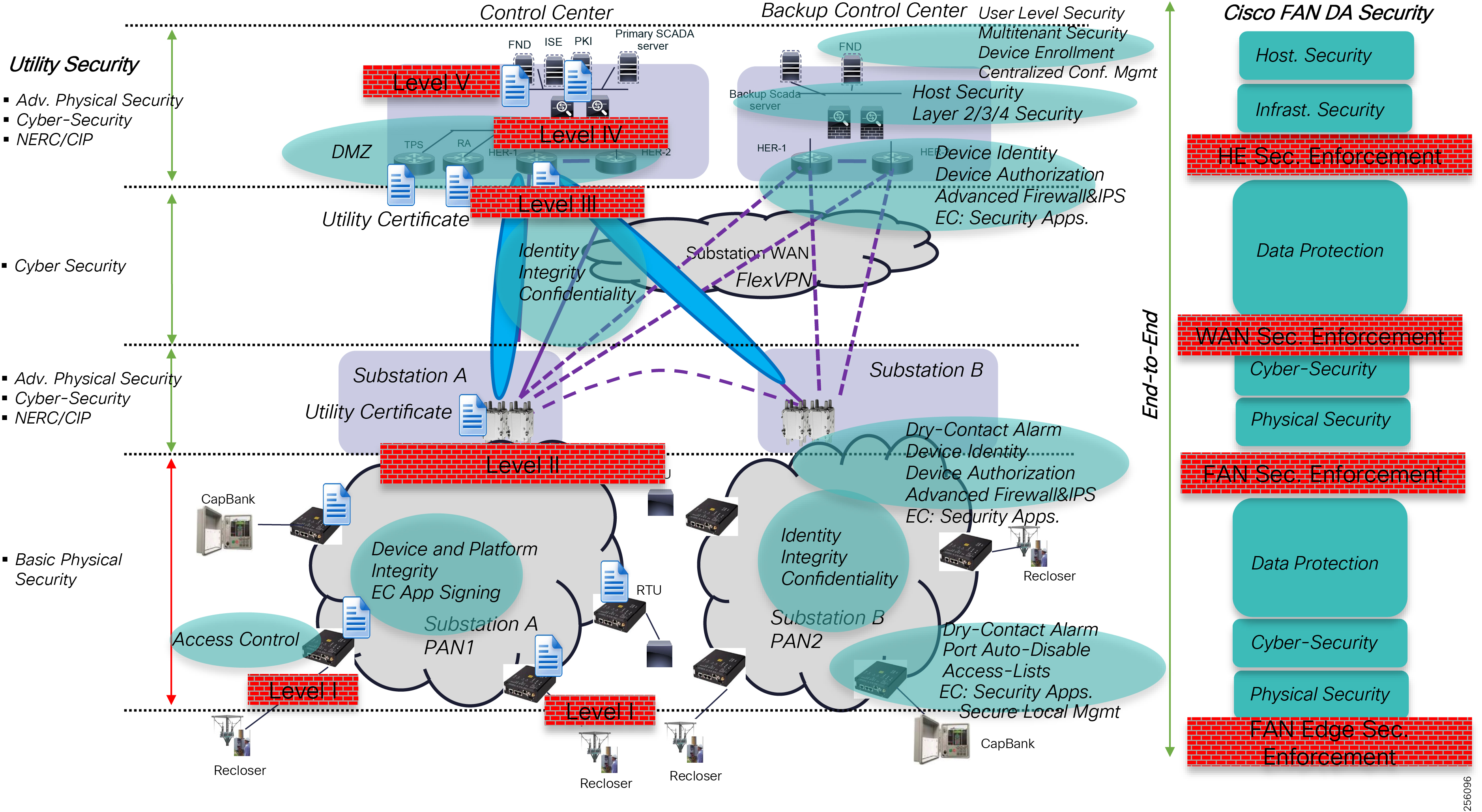
The most vulnerable area of the solution is the FAN infrastructure layer since the grid devices and the Cisco DA gateways are located on the distribution overhead or underground utility assets and no good physical security exists besides an enclosure lock. The new IR510 was built in mind for this real risk; therefore, customers can use the dry-contact alarms with an external sensor to detect when the outdoor-rated enclosure that's housing the communication equipment is opened. This alarm can be correlated with the solution management system to alert operators of unauthorized access. Knowledge of unauthorized access does not solve the temporary problem where somebody could connect to the communication infrastructure and try to reach other locations in the distribution network or the Control Center.
Network administrators should disable the Ethernet port if grid devices are connected via the Serial port. When grid devices are connected via the Ethernet port, then the security feature called Auto-Disable Ethernet Port should be enabled so that when somebody tries to connect another device to the DA Gateway (for example, an unauthorized PC), the IR510's Ethernet port status will go into disabled state. This will prevent any packets entering the Ethernet port and therefore protect the mesh and the local Edge Compute applications.
The DA Gateway is running a special operating system that was designed for constrained, low power devices and does not uses traditional IT management tools like Telnet or other readily available tools to gain access to the device management. Customer will have to use the centralized management system FND or the local field tool called IoT Device Manager.
Device configuration management is centralized; therefore, even if someone would make local device configuration changes, the changes will be overwritten by the FND configuration. One will have to compromise the FND in order to make system changes.
Additionally, each DA Gateway motherboard is equipped with a dedicated security chip that provides:
■![]() Secure unique device identifier (802.1AR)
Secure unique device identifier (802.1AR)
■![]() Immutable identity and certifiable cryptography
Immutable identity and certifiable cryptography
■![]() Entropy source with true randomization
Entropy source with true randomization
■![]() Memory protection and image signing and validation
Memory protection and image signing and validation
■![]() Tamper-proof secure storage of configuration and data
Tamper-proof secure storage of configuration and data
The software images are digitally signed with Cisco certificates to validate the authenticity and integrity of the software.
Another good security feature is the Edge Compute application signature that works with a Trusted Anchor located in the Control Center to enforce application identity (authentication) and authorization; this means that it's allowed to run on the platform.
Customers will have the ability to deploy third party security applications at the edge to inspect traffic coming from the grid devices to enforce edge security.
The second area of concern with any radio network is that somebody could try to intercept the data or even join the mesh with 900Mhz-capable devices. Cisco has implemented IEEE 802.1x as method to securely authenticate a radio node before allowing it to join the mesh PAN or even send packets into the network. Authentication is based on X.509 certificates and ECC that is locally installed in a protected area during the ZTD.
Figure 92 First Rank Device Mesh Joining Process
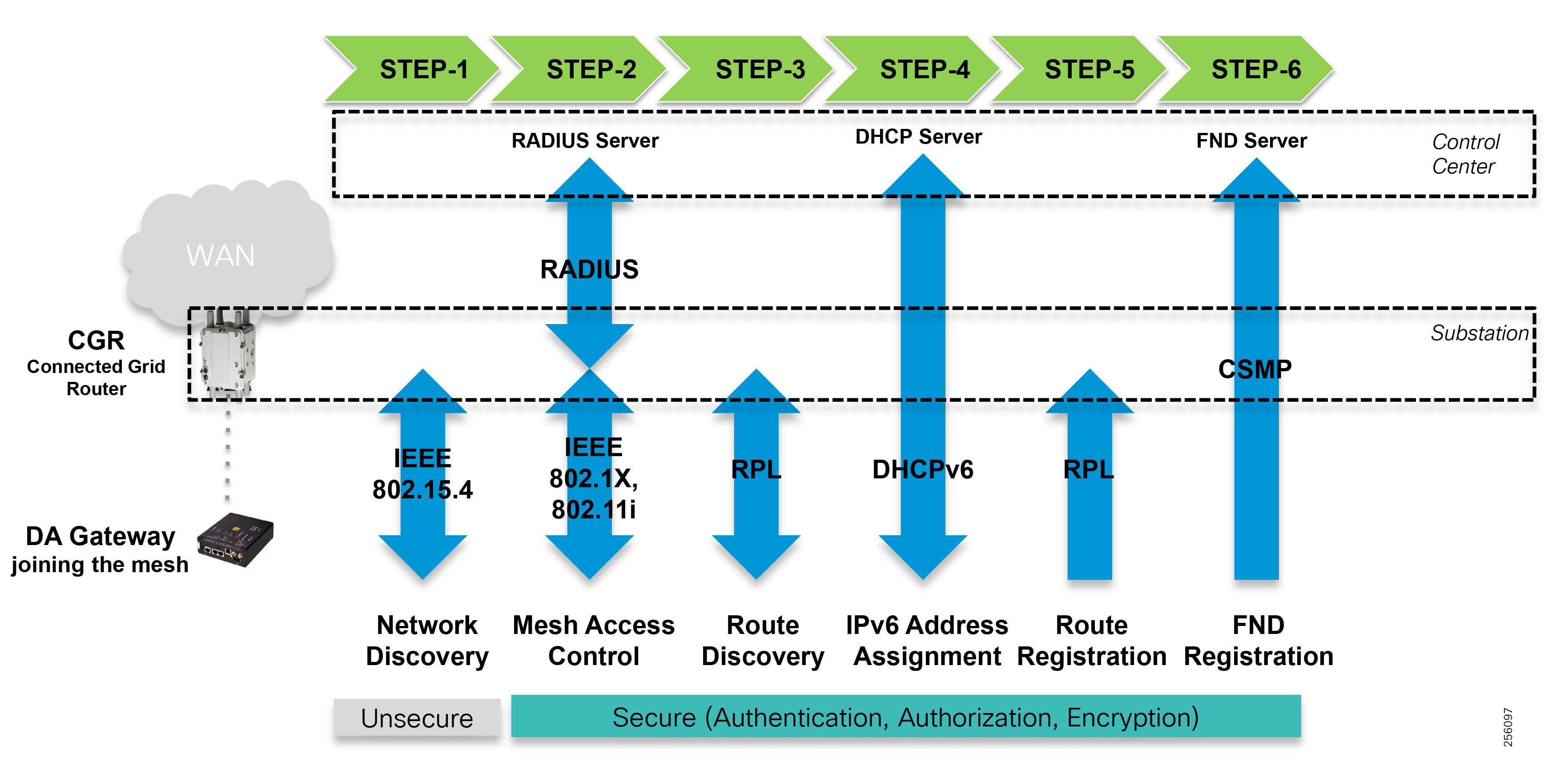
Figure 93 Multi-hop Service Mesh Join Process
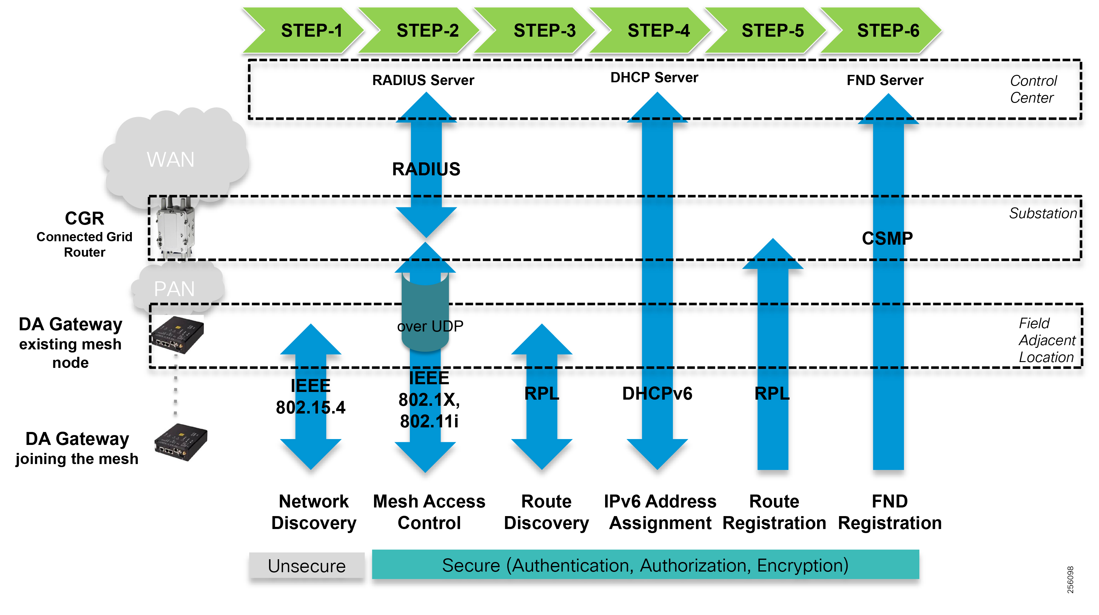
Figure 94 IEEE 802.1x Device Authentication
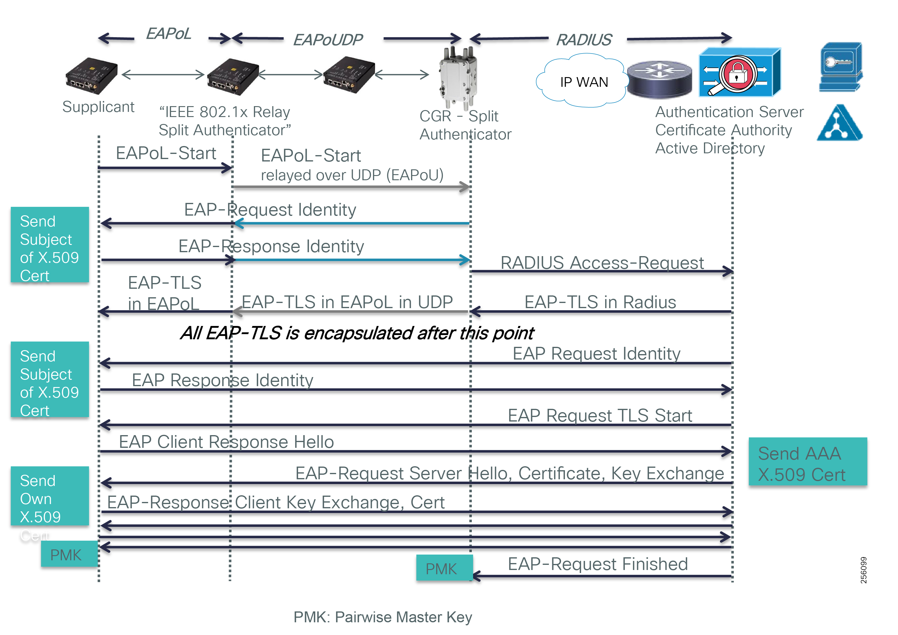
The mesh security also performs authorization to ensure that a device is authorized to get access to the network and that it was not evicted by the administrator for security reasons (compromised or stolen).
The DA gateways perform data link layer encryption where the data is encrypted on a hop-by-hop using AES 128 symmetric encryption algorithm. The only packets that aren't encrypted are the beacon broadcast that announces the PAN information for nodes to discover the mesh network.
When customers implement a security layer within each substation and enable node Inter-PAN migration, then network administrators need to be aware that an inline stateful firewall will break existing sessions between the Grid Systems and the field grid devices when a node migrates between adjacent PANs, especially for TCP protocols.
If it is not acceptable for the grid device session to be turned down and re-established over the new path, then network engineers can enable routing between substations so that grid device sessions enters the WAN through its home substation FAR.
The WAN infrastructure layer also implements a secure VPN solution (FlexVPN), which is based on the open standards IKEv2 and IPSec, so that traffic traversing any type of transport infrastructure, is encrypted and secure. FAR routers support additional type of encryption algorithms based on customer preferences.
FAR routers use RSA certificates to authenticate with the HER and the headend NMSs as well as authorization.
Since FAR routers are not constrained devices and run full IOS operating systems, they can be used as a security enforcement point between the mesh radio network and the rest of the Distribution network. Administrators can configure the security feature: Zone-Based Firewall, which is a stateful firewall combined with IPS signatures. As with the DA gateways, the FAR devices support a dedicated Edge Compute module that will allow customers to install third party security applications.
Typically, the FAR routers are installed within the premise of the substations and are protected by the substation yard fence and the video security system. Therefore, physical security is not critical, but for instances where the FAR is deployed in a field or unsecure location, the FAR router supports the same security features as the DA gateway (such as dry-alarm contacts and the Disable Ethernet port). The FAR router is an IP67-rated devices and physical access inside the chassis is not a simple process due to the secure door bolts. This makes it extremely difficult for any rogue entity to open or uninstall the device from the pole-top mounting. The device generates NMS alerts if the router door or chassis is opened.
As with the DA Gateways, the FAR router motherboard is equipped with a dedicated security chip and provides the same level of security.
In order to ease local troubleshooting and device maintenance, the FAR routers have a Wi-Fi management radio interface that should be disabled during normal operations. In order to connect to the FAR, field engineers would need to have a trouble ticket open and have the access credential installed on their laptop to authenticate using the WPA2 standard.
Note: The Cisco Secondary Substation Design Guide offers additional details about the Control Center design considerations. Refer to the following URL:
■![]() https://www.cisco.com/c/en/us/td/docs/solutions/Verticals/Distributed-Automation/Secondary-Substation/DG/DA-SS-DG/DA-SS-DG-doc.html
https://www.cisco.com/c/en/us/td/docs/solutions/Verticals/Distributed-Automation/Secondary-Substation/DG/DA-SS-DG/DA-SS-DG-doc.html
The Grid Systems and the Resilient Mesh management system in the Control Center are protected by network security devices (Cisco Next-Generation firewalls and IPS), end-host security agents (such as Cisco FireAMP) running on servers and by the security access features running on the switching and routing infrastructure.
The mesh management system control messages between the FND and the FAR or DA gateways are signed to authenticate the source of the message as well as to detect any replay attacks.
Note: The Cisco FAN Headend Implementation Guide offers additional details about the Control Center design considerations. Refer to the following URL:
■![]() https://salesconnect.cisco.com/open.html?c=db570d3f-3212-4659-a306-5f65aeab862b
https://salesconnect.cisco.com/open.html?c=db570d3f-3212-4659-a306-5f65aeab862b
Network Management System
The Resilient Mesh Management System, FND is a software platform that manages network and security infrastructure for multi-service mesh networks and is the core component of the solution.
Note: The Cisco FAN FND product overview is available at the following URL:
■![]() https://www.cisco.com/c/en/us/products/cloud-systems-management/iot-field-network-director/index.html#~stickynav=1
https://www.cisco.com/c/en/us/products/cloud-systems-management/iot-field-network-director/index.html#~stickynav=1
The FND system has the following components:
■![]() FND Application Server —This is the core of mesh deployments. It runs on an RHEL server and allows administrators to control different aspects of the FAN DA solution deployment using its browser-based GUI. It also manages Edge Compute application deployment and configuration. FND Application Server HA deployments include two or more servers connected to a load balancer.
FND Application Server —This is the core of mesh deployments. It runs on an RHEL server and allows administrators to control different aspects of the FAN DA solution deployment using its browser-based GUI. It also manages Edge Compute application deployment and configuration. FND Application Server HA deployments include two or more servers connected to a load balancer.
■![]() FND Database—This Oracle database stores all information managed by the Resilient Mesh solution, including all metrics received from the DA devices and all device properties such as firmware images, configuration templates, logs, and event information.
FND Database—This Oracle database stores all information managed by the Resilient Mesh solution, including all metrics received from the DA devices and all device properties such as firmware images, configuration templates, logs, and event information.
■![]() Software Security Module (SSM)—This is used for signing CoAP Simple Management Protocol (CSMP) messages sent to field devices.
Software Security Module (SSM)—This is used for signing CoAP Simple Management Protocol (CSMP) messages sent to field devices.
■![]() TPS Proxy—Allows FARs to communicate with headend systems when they first start up in the field. After the FND provisions tunnels between the FARs and ASRs, the FARs communicate with the FND directly.
TPS Proxy—Allows FARs to communicate with headend systems when they first start up in the field. After the FND provisions tunnels between the FARs and ASRs, the FARs communicate with the FND directly.
The FND is responsible for the full life cycle network management tasks: Fault management, configuration management, accounting management, performance management, and security management (FCAPS). The FND uses the CSMP for remote configuration, monitoring and event generation over the IPv6 network.
Features and capabilities of the FND include:
■![]() Configuration Management—Facilitates configuration of large numbers of Cisco CGRs. They can be bulk-configured by placing them into configuration groups, editing settings in a configuration template, and then pushing the configuration to all devices in the group.
Configuration Management—Facilitates configuration of large numbers of Cisco CGRs. They can be bulk-configured by placing them into configuration groups, editing settings in a configuration template, and then pushing the configuration to all devices in the group.
■![]() Device and Event Monitoring—Displays easy-to-read tabular views of extensive information generated by devices, allowing monitoring the network for errors. Cisco CG-NMS provides integrated Geographic Information System (GIS) map-based visualization of FAN devices such as routers and smart meters. CG-NMS can be used to create CGR-specific work orders that include the required certificates to access the router.
Device and Event Monitoring—Displays easy-to-read tabular views of extensive information generated by devices, allowing monitoring the network for errors. Cisco CG-NMS provides integrated Geographic Information System (GIS) map-based visualization of FAN devices such as routers and smart meters. CG-NMS can be used to create CGR-specific work orders that include the required certificates to access the router.
■![]() Firmware Management—Serves as a repository for Cisco CGR and DA Gateway firmware images. Cisco FND can be used to upgrade the firmware running on groups of devices by loading the firmware image file onto the Cisco FND server, and then uploading the image to the devices in the group. Once uploaded, FND can be used to install the firmware image directly on the devices.
Firmware Management—Serves as a repository for Cisco CGR and DA Gateway firmware images. Cisco FND can be used to upgrade the firmware running on groups of devices by loading the firmware image file onto the Cisco FND server, and then uploading the image to the devices in the group. Once uploaded, FND can be used to install the firmware image directly on the devices.
■![]() Zero Touch Deployment—This easy-to-use feature automatically registers (enrolls) and distributes X.509 certificates and provisioning information over secure connections within a connected grid network.
Zero Touch Deployment—This easy-to-use feature automatically registers (enrolls) and distributes X.509 certificates and provisioning information over secure connections within a connected grid network.
■![]() ODM File Upload and Hash Compatibility—Operational Data Model (ODM) files format commands that execute on Cisco IOS routers. The FND uses the formatted output for such things as periodic metrics collection, router version information, battery information, reading the Hypervisor (virtual machine monitor) version, and GPS information. ODM file hash compatibility and upload are performed while requesting a registration, during periodic inventory updates, or during the tunnel provisioning process.
ODM File Upload and Hash Compatibility—Operational Data Model (ODM) files format commands that execute on Cisco IOS routers. The FND uses the formatted output for such things as periodic metrics collection, router version information, battery information, reading the Hypervisor (virtual machine monitor) version, and GPS information. ODM file hash compatibility and upload are performed while requesting a registration, during periodic inventory updates, or during the tunnel provisioning process.
■![]() Tunnel Provisioning Between HERs and FARs—Protects data exchanged between Cisco HERs and Cisco CGRs and prevents unauthorized access to Cisco CGRs, to provide secure communication between devices. Cisco FND can execute CLI commands to provision secure tunnels between Cisco CGRs and Cisco HERs. The FND can be used to bulk-configure tunnel provisioning using groups.
Tunnel Provisioning Between HERs and FARs—Protects data exchanged between Cisco HERs and Cisco CGRs and prevents unauthorized access to Cisco CGRs, to provide secure communication between devices. Cisco FND can execute CLI commands to provision secure tunnels between Cisco CGRs and Cisco HERs. The FND can be used to bulk-configure tunnel provisioning using groups.
■![]() IPv6 RPL Tree Polling—A node in the IPv6 Routing Protocol for Low power and Lossy Networks (RPL) tree discovers its neighbors and establishes routes using ICMPv6 message exchanges. RPL manages routes based on the relative position of the DA Gateway to the CGR that is the root of the routing tree. RPL tree polling is available through the mesh nodes and CGR periodic updates. The RPL tree represents the mesh topology, which is useful for troubleshooting. For example, the hop count information received from the RPL tree can determine the use of unicast or multicast for the firmware download process. The FND maintains a periodically updated snapshot of the RPL tree.
IPv6 RPL Tree Polling—A node in the IPv6 Routing Protocol for Low power and Lossy Networks (RPL) tree discovers its neighbors and establishes routes using ICMPv6 message exchanges. RPL manages routes based on the relative position of the DA Gateway to the CGR that is the root of the routing tree. RPL tree polling is available through the mesh nodes and CGR periodic updates. The RPL tree represents the mesh topology, which is useful for troubleshooting. For example, the hop count information received from the RPL tree can determine the use of unicast or multicast for the firmware download process. The FND maintains a periodically updated snapshot of the RPL tree.
■![]() Edge Compute Support—For Cisco IOS CGR1000 devices that support the Cisco Compute Module (CGM), the FND allows approved users to manage applications running on the supported operating systems. The FND manages the application deployment and displays application status and the Hypervisor version running on the device.
Edge Compute Support—For Cisco IOS CGR1000 devices that support the Cisco Compute Module (CGM), the FND allows approved users to manage applications running on the supported operating systems. The FND manages the application deployment and displays application status and the Hypervisor version running on the device.
■![]() Device Location Tracking—For CGR 1000 devices, the FND displays real-time location and device location history.
Device Location Tracking—For CGR 1000 devices, the FND displays real-time location and device location history.
■![]() Software Security Module (SSM)—This is a low-cost alternative to the Hardware Security Module (HSM) and is used for signing CSMP messages sent to meters.
Software Security Module (SSM)—This is a low-cost alternative to the Hardware Security Module (HSM) and is used for signing CSMP messages sent to meters.
■![]() Diagnostics and Troubleshooting—The CG-NMS rule engine infrastructure provides effective monitoring of triage-based troubleshooting. Device troubleshooting runs on-demand device path trace and ping on any CGR, range extender, or meter (mesh endpoints).
Diagnostics and Troubleshooting—The CG-NMS rule engine infrastructure provides effective monitoring of triage-based troubleshooting. Device troubleshooting runs on-demand device path trace and ping on any CGR, range extender, or meter (mesh endpoints).
■![]() High Availability—To ensure uninterrupted network management and monitoring, the Cisco FND solution can be deployed in a High Availability configuration. By using clusters of load-balanced FND servers and primary and standby FND databases, the Cisco FND constantly monitors the health of the system, including connectivity within clusters and server resource usage. If a server cluster member or database becomes unavailable or a tunnel fails, another takes its place seamlessly.
High Availability—To ensure uninterrupted network management and monitoring, the Cisco FND solution can be deployed in a High Availability configuration. By using clusters of load-balanced FND servers and primary and standby FND databases, the Cisco FND constantly monitors the health of the system, including connectivity within clusters and server resource usage. If a server cluster member or database becomes unavailable or a tunnel fails, another takes its place seamlessly.
■![]() Power Outage Notifications—DA Gateways implement a power outage notification service to support timely and efficient reporting of power outages. In the event of a power outage, nodes perform the necessary functions to conserve energy and notify neighboring nodes of the outage. The FARs relay the power outage notification to the FND, which then issues push notifications to customers to relate information on the outage.
Power Outage Notifications—DA Gateways implement a power outage notification service to support timely and efficient reporting of power outages. In the event of a power outage, nodes perform the necessary functions to conserve energy and notify neighboring nodes of the outage. The FARs relay the power outage notification to the FND, which then issues push notifications to customers to relate information on the outage.
■![]() Mesh Upgrade Support—Over-the-air software and firmware upgrades to field devices such as Cisco CGRs and DA Gateways.
Mesh Upgrade Support—Over-the-air software and firmware upgrades to field devices such as Cisco CGRs and DA Gateways.
■![]() Audit Logging—Logs access information for user activity for audit, regulatory compliance, and Security Event and Incident Management (SEIM) integration. This simplifies management and enhances compliance by integrated monitoring, reporting, and troubleshooting capabilities.
Audit Logging—Logs access information for user activity for audit, regulatory compliance, and Security Event and Incident Management (SEIM) integration. This simplifies management and enhances compliance by integrated monitoring, reporting, and troubleshooting capabilities.
■![]() North Bound APIs—Eases integration of existing utility applications such as outage management system (OMS), meter data management (MDM), trouble-ticketing systems, and manager-of-managers.
North Bound APIs—Eases integration of existing utility applications such as outage management system (OMS), meter data management (MDM), trouble-ticketing systems, and manager-of-managers.
■![]() Work Orders for Device Manager—Credentialed field technicians can remotely access and update work orders.
Work Orders for Device Manager—Credentialed field technicians can remotely access and update work orders.
■![]() Role-Based Access Controls (RBAC)—Integrates with enterprise security policies and role-based access control for DA Gateway network devices.
Role-Based Access Controls (RBAC)—Integrates with enterprise security policies and role-based access control for DA Gateway network devices.
■![]() Event and Issue Management—Fault event collection, filtering, and correlation for communication network monitoring. The FND supports a variety of fault-event mechanisms for threshold-based rule processing, custom alarm generation, and alarm event processing. Faults display on a color-coded GIS-map view for various endpoints in the utility network. This allows operator-level custom, fault-event generation, processing, and forwarding to various utility applications such as an outage management system. Automatic issue tracking is based on the events collected.
Event and Issue Management—Fault event collection, filtering, and correlation for communication network monitoring. The FND supports a variety of fault-event mechanisms for threshold-based rule processing, custom alarm generation, and alarm event processing. Faults display on a color-coded GIS-map view for various endpoints in the utility network. This allows operator-level custom, fault-event generation, processing, and forwarding to various utility applications such as an outage management system. Automatic issue tracking is based on the events collected.
FAN DA Device Onboarding: Device Registration and Configuration Processing
A FAN DA solution makes it easy for customers to deploy and connect a large amount of communication equipment in a short period of time by leveraging a simplified device provisioning process. The ISM band devices and the cellular FAN DA devices can be automatically onboarded through the ZTD process.
The FAN DA solution supports two ZTD models for the field router devices:
■![]() ZTD 1.0-Device onboarding with manual bootstrap configuration
ZTD 1.0-Device onboarding with manual bootstrap configuration
■![]() ZTD 2.0-Complete automatic device onboarding including bootstrap configuration via PnP
ZTD 2.0-Complete automatic device onboarding including bootstrap configuration via PnP
FAN field device onboarding refers to all the processes (device bootstrapping, device authentication and authorization, device certificate enrollment, configuration provisioning, etc.) that have to occur before a network device becomes operational and is fully managed by the network management (in this case, the Field Network Director or FND).
Cisco offers two FAN DA solutions—one based on free license spectrum ISM 900 MHz band and the other based on managed cellular service 4G/LTE. The next section will detail the different device onboarding options available with each FAN DA solution.
Unlicensed 900 MHz ISM FAN DA Solution Device Onboarding Overview
For the FAN DA ISM-based solution, the infrastructure layer provisioning is done in a sequential two-step process. First, the FAR devices (CGR) must be provisioned since each CGR acts as a mesh PAN coordinator that advertises the mesh information for FD devices to join. Once the FAR devices are operational, then FD devices can also join the mesh network and go through the ZTD process.
1.![]() Provision FAR devices for a specific area.
Provision FAR devices for a specific area.
2.![]() Provision FD devices for that area.
Provision FD devices for that area.
Today, the FAN DA ISM solution supports the device onboarding methods shown in Table 48:
|
|
|
|
|
ZTD 1.0 uses the original method to onboard devices onto the network, which requires that administrators apply a small basic device configuration part of the device bootstrap configuration process before the remaining onboarding processes can take place without human intervention. Because network devices need to be manually configured, this type of deployment typically uses a staging facility. During the staging phase, customers or partners, in addition to applying the bootstrap configuration, can perform local device firmware and software updates at a faster pace, which will minimize any issues that could arise in the field, update asset inventory system, and pre-provision device accounts in the network management systems.
Figure 95 Device Onboarding using ZTD 1.0
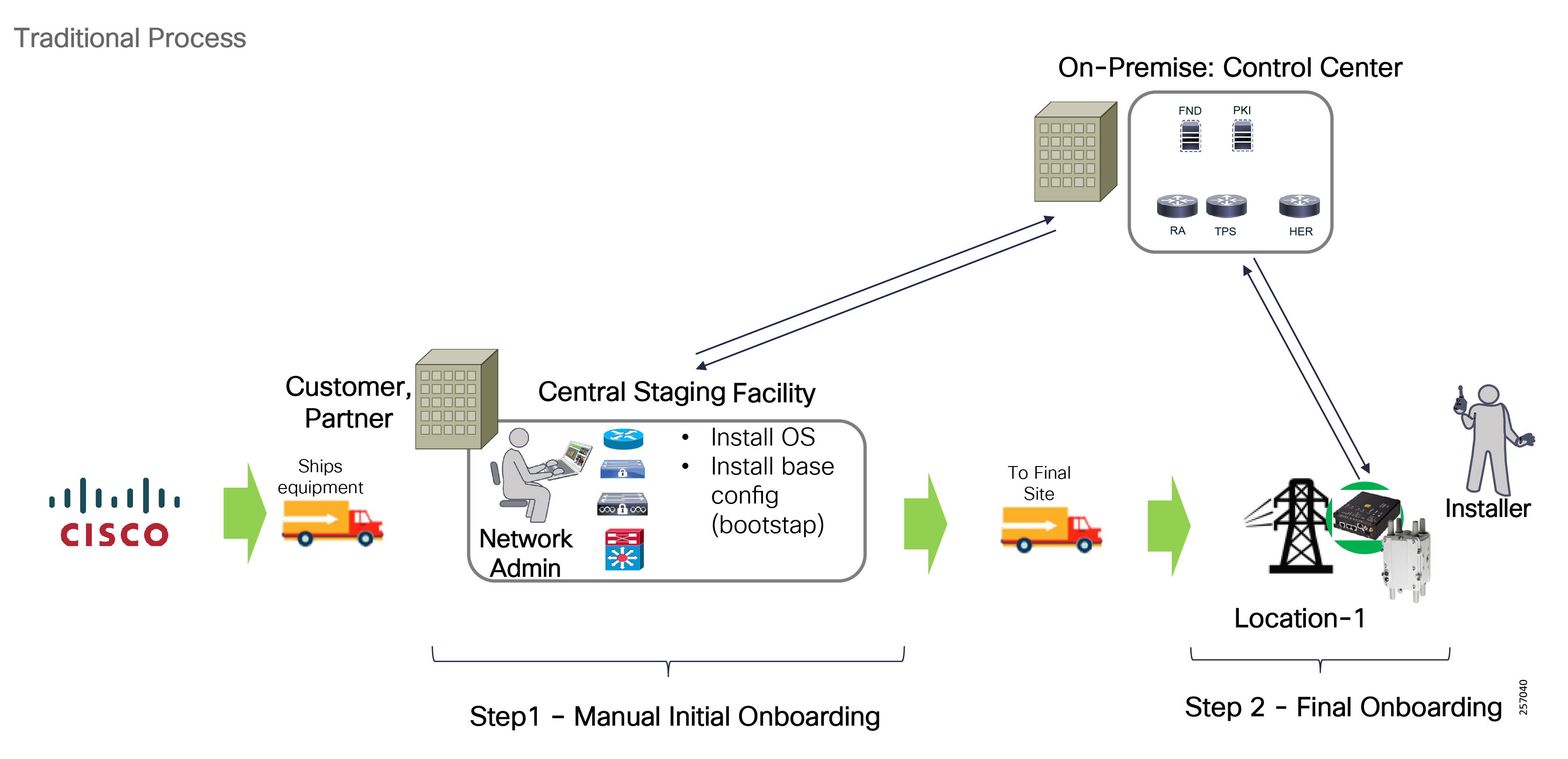
During this phase, it is recommended to validate the ZTD process on a few devices to validate the bootstrap configuration and the success of the remaining processes (device certificate enrollment, etc.) in order to avoid any additional work once the device is deployed in the field.
Devices onboarding has the four stages shown in Figure 96:
Figure 96 Device Onboarding Phases Overview
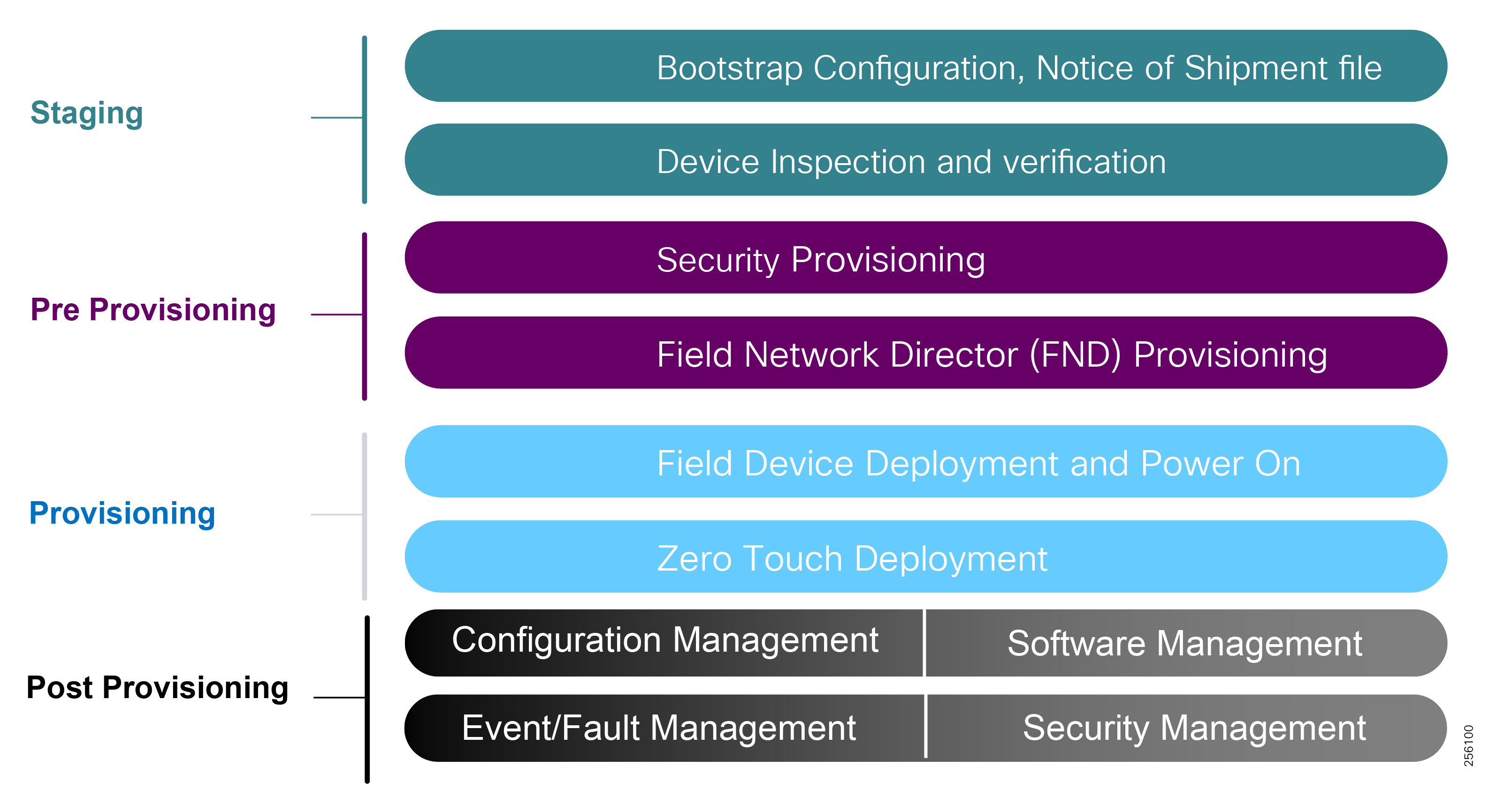
■![]() Staging can be done at a customer location or a partner warehouse location where the equipment order is shipped to for inventory, initial device configuration (bootstrapping), and temporary storage purposes until the deployment phase.
Staging can be done at a customer location or a partner warehouse location where the equipment order is shipped to for inventory, initial device configuration (bootstrapping), and temporary storage purposes until the deployment phase.
■![]() The Pre-Provisioning stage is done by the customer or trusted partner once the headend infrastructure is built. Each device needs to have a pre-configured device account into the management systems (AD, FND, etc.) so that device authentication and authorization can be enforced during the device Provisioning phase.
The Pre-Provisioning stage is done by the customer or trusted partner once the headend infrastructure is built. Each device needs to have a pre-configured device account into the management systems (AD, FND, etc.) so that device authentication and authorization can be enforced during the device Provisioning phase.
■![]() The Provisioning stage is an automatic process that occurs during the equipment field deployment phase when devices go through the ZTD process and transition to operation-ready state.
The Provisioning stage is an automatic process that occurs during the equipment field deployment phase when devices go through the ZTD process and transition to operation-ready state.
■![]() Post-Provisioning is the last stage in the device onboarding effort when administrators can address any security concerns, push firmware and software updates, remove temporary accounts, and change the device state from operation-ready to production.
Post-Provisioning is the last stage in the device onboarding effort when administrators can address any security concerns, push firmware and software updates, remove temporary accounts, and change the device state from operation-ready to production.
Field Area Routers (FAR) Device Onboarding using ZTD 1.0 (Manual Bootstrapping)
Customers can use the ZTD feature in a secure way to automate the field device deployment process. Network administrators only need to manually configure the CGR router bootstrap configuration (WAN interface IP address, AAA information, Certificate Enrollment, etc.) part of the bootstrapping configuration step, so the router can contact the RA and TPS and go through the certificate enrollment process.
Figure 97 provides an illustration of ZTD staging by the FND.
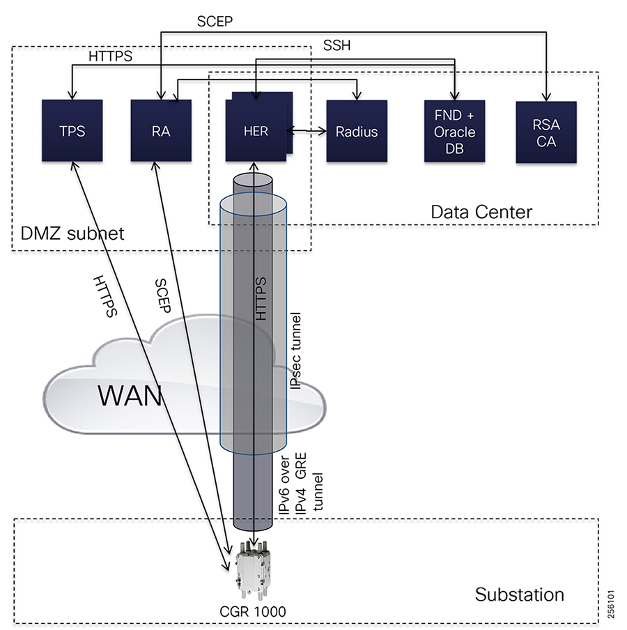
The FND is located in the Utility private network, while the Cisco Tunnel Provisioning Server proxy (TPS proxy) and Registration Authority (RA) are located in the DMZ.
After installing and powering on the CGR 1000, it becomes active in the network and registers its certificate with the RA by employing the Simple Certificate Enrollment Protocol (SCEP). The RA functioning as a CA proxy, obtains certificates for the Cisco CGR from the CA. The Cisco CGR then sends a tunnel provisioning request over HTTPS to the TPS proxy that forwards it to FND. Cisco FND pushes the configuration to create a tunnel between Cisco CGRs and the headend router (HER).
FAR Device Onboarding using ZTD 2.0 (PnP)
With FND version 4.3, customers don't have to manually bootstrap the FAR configuration any more. They can take advantage of router PnP functionality where the router can receive the TPS or FND IP addresses information via different discovery mechanisms in order to download the router bootstrap configuration from the PnP server. FAR routers can use the manufacturer's device birth certificate Secure Unique Device Identifier (SUDI) certificate to authenticate and establish a secure connection with the PnP Proxy or PnP server depending on the deployment type.
Figure 98 depicts the main stages of the process.
Figure 98 Field Area Router Device Onboarding Overview
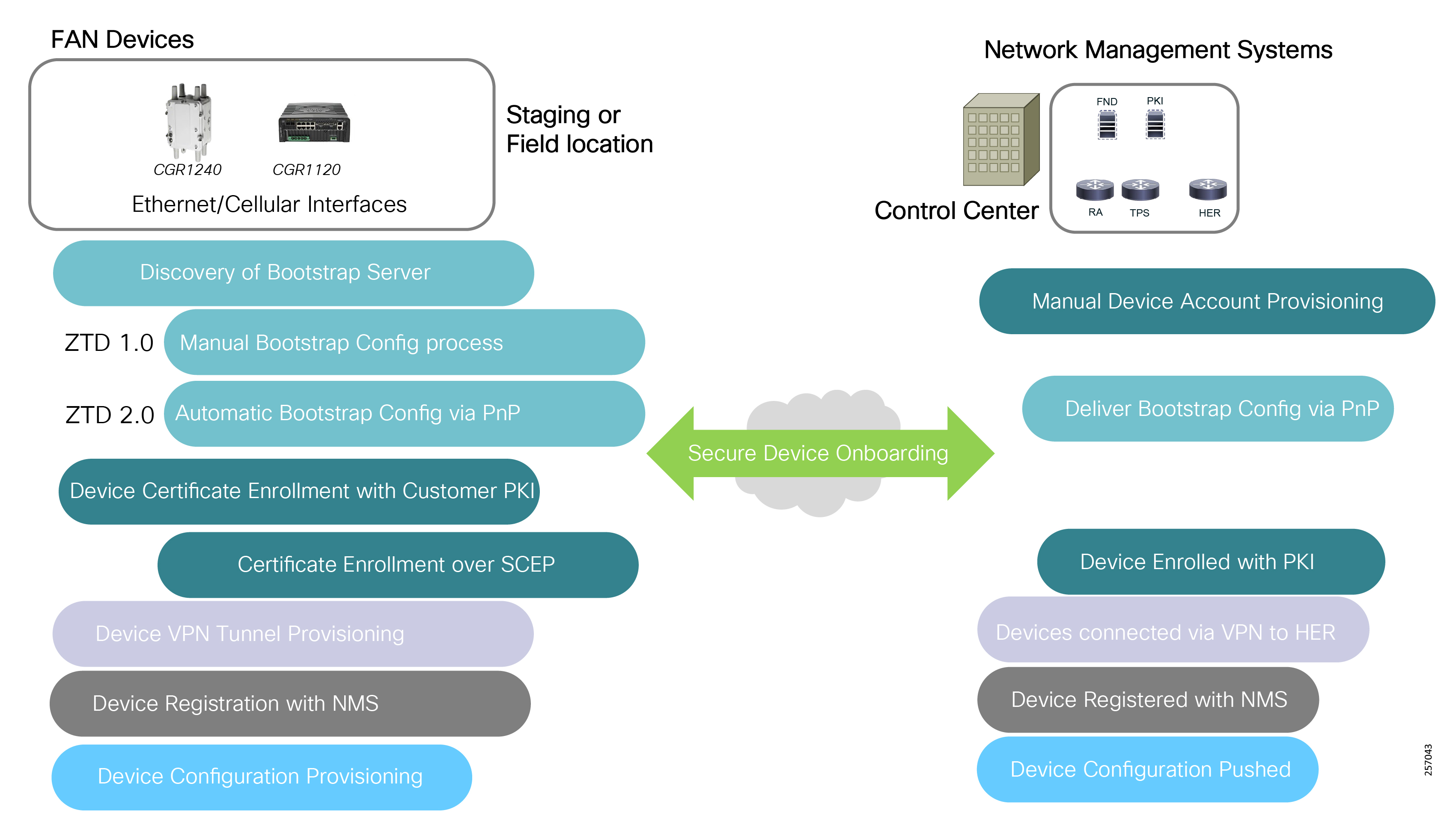
Using ZTD 2.0, FAR devices can leverage Cisco PnP solution to automate the device bootstrap configuration step. This approach reduces the burden on customers by greatly simplifying the process of deploying new devices. An installer at the site can deploy a new device without any CLI knowledge, while a network administrator centrally manages device configuration.
The Cisco Network PnP solution provides a simple, secure, unified, and integrated offering for customers to ease new field device roll-outs or for provisioning updates to an existing network. The solution provides a unified approach to provision the distribution automation communication infrastructure comprised of Cisco DA gateways, with a near ZTD experience.
The Cisco PnP solution has the following components:
■![]() PnP Agent—The agent is embedded in Cisco devices and communicates to the Cisco Network Plug and Play application using the open plug and play protocol over HTTPS during device deployments. The PnP Agent, using DHCP, DNS, or other such methods, tries to acquire the IP address of the PnP server with which it wants to communicate. After a server is found and a connection has been established, the agent communicates with the PnP server to perform deployment-related activities.
PnP Agent—The agent is embedded in Cisco devices and communicates to the Cisco Network Plug and Play application using the open plug and play protocol over HTTPS during device deployments. The PnP Agent, using DHCP, DNS, or other such methods, tries to acquire the IP address of the PnP server with which it wants to communicate. After a server is found and a connection has been established, the agent communicates with the PnP server to perform deployment-related activities.
■![]() PnP Proxy—An optional agent that runs on a Linux server. The FAN solution architecture uses the TPS server located in the DMZ as a PnP Proxy to increase the solution security. During device onboarding, all communication between field routers and FND located in the Control Center trusted zone takes place via TPS server.
PnP Proxy—An optional agent that runs on a Linux server. The FAN solution architecture uses the TPS server located in the DMZ as a PnP Proxy to increase the solution security. During device onboarding, all communication between field routers and FND located in the Control Center trusted zone takes place via TPS server.
■![]() PnP Server—The Cisco FND is a central server that functions as a PnP Server that encodes the logic of managing and distributing deployment information (images and configurations) for the devices being deployed. The FND PnP Server communicates with the PnP agent on the device using PnP protocol. The platform uses multiple Northbound REST APIs that drive core network automation solutions (Device Certificate Enrollment, etc.). The Cisco APIC-EM management tool can also be used as a PnP Server.
PnP Server—The Cisco FND is a central server that functions as a PnP Server that encodes the logic of managing and distributing deployment information (images and configurations) for the devices being deployed. The FND PnP Server communicates with the PnP agent on the device using PnP protocol. The platform uses multiple Northbound REST APIs that drive core network automation solutions (Device Certificate Enrollment, etc.). The Cisco APIC-EM management tool can also be used as a PnP Server.
■![]() PnP Protocol—The PnP Protocol defines the transport bindings and schemas for various messages that are exchanged between the PnP Agent and PnP Server over HTTP or HTTPS (HTTPS being preferred for security reasons).
PnP Protocol—The PnP Protocol defines the transport bindings and schemas for various messages that are exchanged between the PnP Agent and PnP Server over HTTP or HTTPS (HTTPS being preferred for security reasons).
■![]() PnP Connect—An optional cloud component for automatic PNP server discovery if the DHCP or DNS methods are not available. The PNP Server is the backend part of the Cisco Network Plug and Play application in the APIC-EM. The Cisco network device contacts the Cisco Plug and Play Connect cloud service at devicehelper.cisco.com to obtain the IP address of the appropriate PNP server that is defined for your organization. The FAN solution Cisco PnP Connect Server information is the TPS IP address.
PnP Connect—An optional cloud component for automatic PNP server discovery if the DHCP or DNS methods are not available. The PNP Server is the backend part of the Cisco Network Plug and Play application in the APIC-EM. The Cisco network device contacts the Cisco Plug and Play Connect cloud service at devicehelper.cisco.com to obtain the IP address of the appropriate PNP server that is defined for your organization. The FAN solution Cisco PnP Connect Server information is the TPS IP address.
■![]() PnP Application—A mobile application for iOS and Android devices that helps configure Cisco devices with a bootstrap configuration and triggers remote branch deployments. The app communicates with the Cisco Network Plug and Play application over 3G/4G/Wi-Fi connections to get the predefined device bootstrap configuration, and delivers it to a Cisco network device by using a special serial cable that is physically connected to the device.
PnP Application—A mobile application for iOS and Android devices that helps configure Cisco devices with a bootstrap configuration and triggers remote branch deployments. The app communicates with the Cisco Network Plug and Play application over 3G/4G/Wi-Fi connections to get the predefined device bootstrap configuration, and delivers it to a Cisco network device by using a special serial cable that is physically connected to the device.
When a Cisco FAR device boots up and no startup configuration is present, the PnP Agent will go through a PnP Server Discovery Phase to acquire the PnP Server IP address so that the FAR devices can download their bootstrap configuration. This bootstrap device configuration will prepare the device for the Device Certificate Enrollment step, VPN tunnel provisioning to the HER, and device registration with FND to download the final device configuration.
PnP Agent supports the following PnP Discovery mechanisms:
■![]() DHCP Server Assist—Uses additional DHCP options 60 and 43 for IPv4 and option 9 for IPv6 to provide the PnP Server information during device DHCP IP address assignment.
DHCP Server Assist—Uses additional DHCP options 60 and 43 for IPv4 and option 9 for IPv6 to provide the PnP Server information during device DHCP IP address assignment.
■![]() DHCP Snooping—Used when the third party DHCP server does not support an additional option and where the Cisco network infrastructure is configured for DHCP Snooping and can insert DHCP options in the third party DHCP response.
DHCP Snooping—Used when the third party DHCP server does not support an additional option and where the Cisco network infrastructure is configured for DHCP Snooping and can insert DHCP options in the third party DHCP response.
■![]() DNS Server Lookup—The device query the DNS servers provided during the DHCP IP address assignment for a default fqdn: pnpserver.localdomain.
DNS Server Lookup—The device query the DNS servers provided during the DHCP IP address assignment for a default fqdn: pnpserver.localdomain.
■![]() PnP Connect (Cloud Redirect)—Device connects to https://devicehelper.cisco.com/ portal to receive its bootstrap configuration or the PnP Server IP address for redirection.
PnP Connect (Cloud Redirect)—Device connects to https://devicehelper.cisco.com/ portal to receive its bootstrap configuration or the PnP Server IP address for redirection.
■![]() USB-based Bootstrapping—USB thumb drive with a bootstrap configuration using a specific file directory and name: router-confg/router.cfg/ciscortr.cfg.
USB-based Bootstrapping—USB thumb drive with a bootstrap configuration using a specific file directory and name: router-confg/router.cfg/ciscortr.cfg.
■![]() Static Configuration—Network administrator configures the PnP Server information on the device.
Static Configuration—Network administrator configures the PnP Server information on the device.
The PnP DHCP and DNS options are documented as part of the "Zero Touch Deployment" chapter in the Cisco Distribution Automation Secondary Substation Design Guide. This design guide release details the device onboarding using the PnP Connect option.
Note: To view the Cisco Distribution Automation Secondary Substation Design Guide, please use the following link:
■![]() https://www.cisco.com/c/en/us/td/docs/solutions/Verticals/Distributed-Automation/Secondary-Substation/DG/DA- SS-DG/DA-SS-DG-doc.html
https://www.cisco.com/c/en/us/td/docs/solutions/Verticals/Distributed-Automation/Secondary-Substation/DG/DA- SS-DG/DA-SS-DG-doc.html
Note: For detailed information on PnP Discovery Phase, please refer to the following device configuration guide:
■![]() https://www.cisco.com/c/en/us/td/docs/ios-xml/ios/pnp/configuration/xe-16-6/pnp-xe-16-6-book.html - reference_jdp_qgc_dy
https://www.cisco.com/c/en/us/td/docs/ios-xml/ios/pnp/configuration/xe-16-6/pnp-xe-16-6-book.html - reference_jdp_qgc_dy
Automatic Device Bootstrapping Configuration using PnP Connect
Customers can leverage the PnP Connect option to fully automate the device onboarding process. At a high level, a brand new device with no startup configuration in the NVRAM will use by default the PnP agent running as a service on the Cisco device operating system (IOS or IOS-XE) to contact the Cisco.com PnP Connect service using a specific URL: https://devicehelper.cisco.com/
Figure 99 Cisco PnP Connect Solution Overview
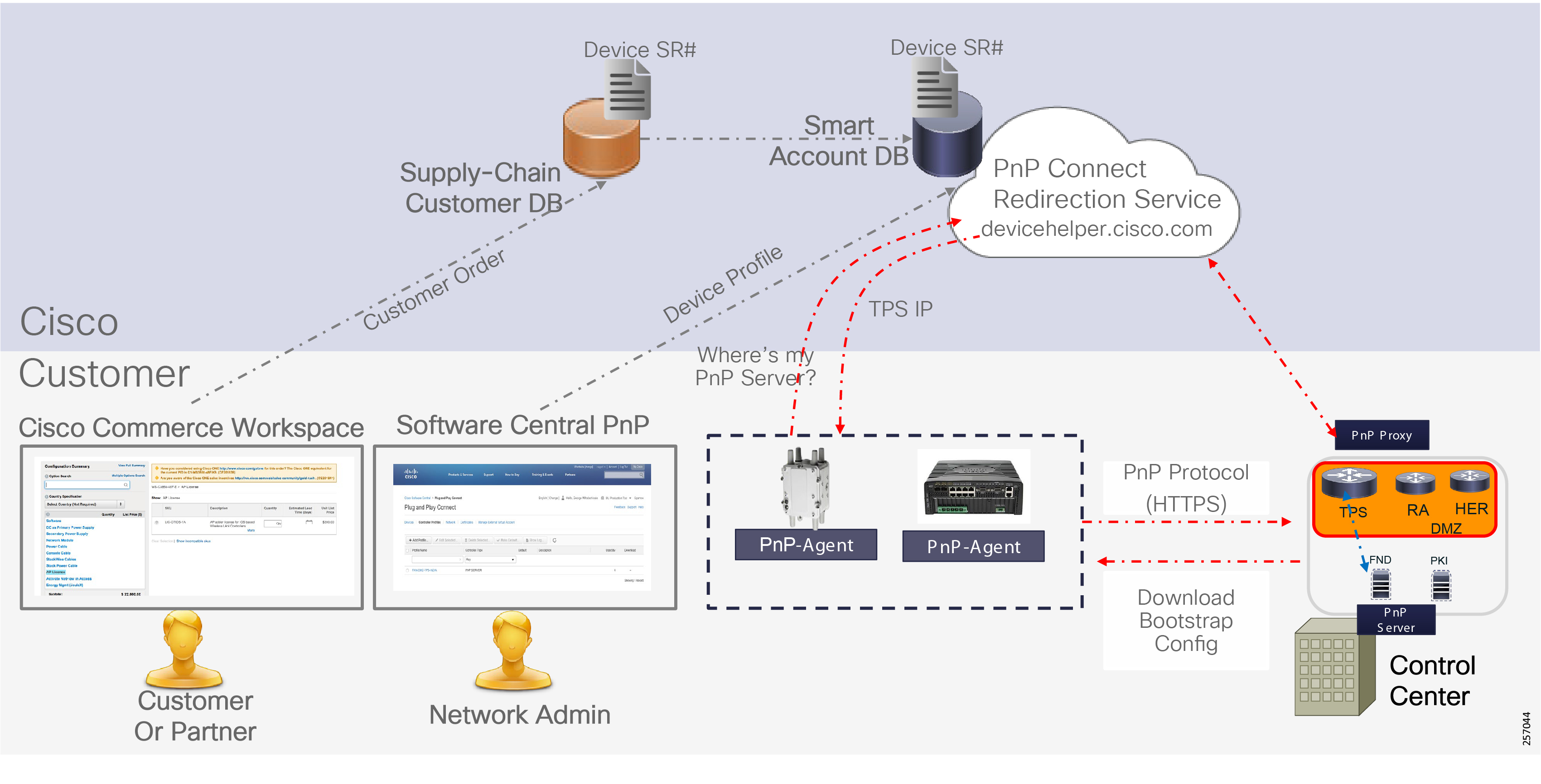
The Cisco PnP solution has integrated the customer device ordering process in the Cisco Commerce Workspace (CCW) into the PnP solution. Customers can provide the company Smart Account during ordering to simplify the device entry process in the Software Central PnP Connect portal. For devices that were ordered without a Smart Account, customers can either manually enter each device or perform a bulk import.
Network administrators will need to create a Controller Profile to specify the TPS server IP address and associate all the field devices with this Controller Profile.
Figure 100 PnP Connect Controller Profile
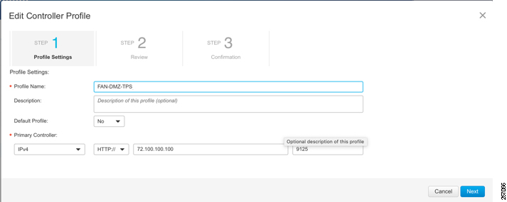
|
|
|
|
|
|
|
|
|
|
|
|
|
|
|
|
|
Figure 101 Device and Controller Mapping
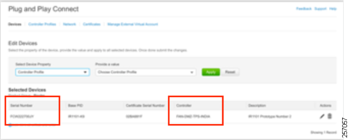
Cisco FAR ZTD is supported over Ethernet interfaces and over Cellular 4G/LTE network interfaces. Both scenarios require that the network infrastructure or the Service Provider Cellular network offer the following services:
■![]() In case of cellular, the cellular modem has a SIM inserted and it's been activated on the SP network
In case of cellular, the cellular modem has a SIM inserted and it's been activated on the SP network
■![]() Dynamic IP address assignment is enabled
Dynamic IP address assignment is enabled
■![]() DNS information is provided during address assignment
DNS information is provided during address assignment
■![]() PnP agent can communicate with https://devicehelper.cisco.com
PnP agent can communicate with https://devicehelper.cisco.com
Cisco FAR ZTD 2.0 over Ethernet Interface
When the FAR router backhaul is an Ethernet interface, the CGR router is either directly connected to the Substation LAN or to a third-party private radio network, which could be Microwave or licensed cellular service. Both scenarios use private network service and do not have internet services enabled; therefore, it makes more sense to use the PnP Agent DHCP or DNS discovery options than the PnP Connect option.
However, if the customer wants to use PnP Connect over their private network, they will need to allow the FAR to reach the internet and communicate with the PnP Connect Service using the devicehelper.cisco.com FQDN. This can be achieved by building a routing path over the IT WAN network and configure the security appliances to allow the PnP traffic.
Figure 102 FAR ZTD 2.0 over Ethernet
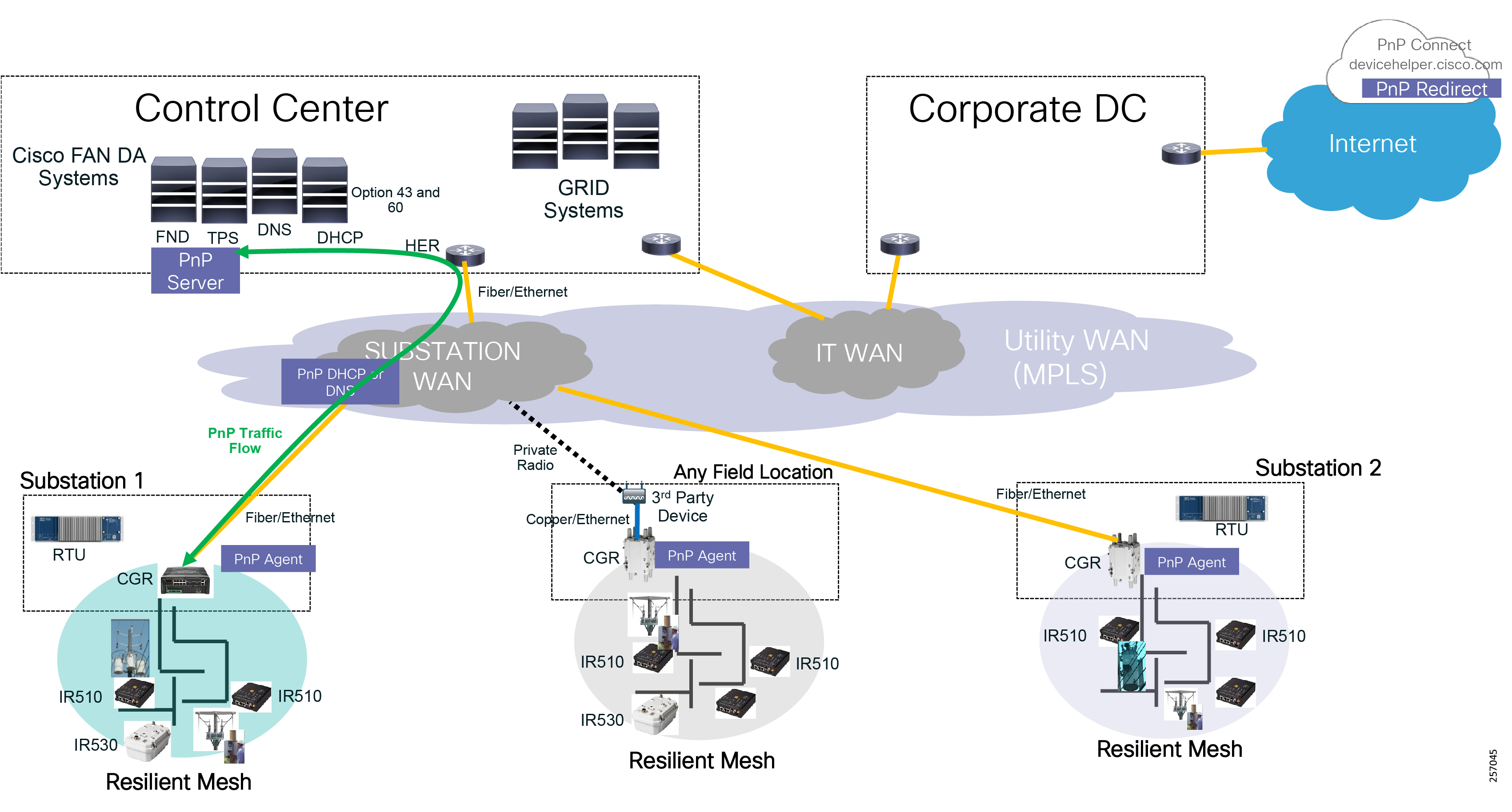
Note: The device startup configuration must be empty in NVRAM for the PnP process to start. Also, since there is no startup configuration, the CGR router software image must be installed with a specific parameter that gets a saved Rommon Boot variable. For more information, please read the following documentation:
■![]() https://www.cisco.com/c/en/us/td/docs/routers/access/800/829/15-7-3M1-Release-Note.html
https://www.cisco.com/c/en/us/td/docs/routers/access/800/829/15-7-3M1-Release-Note.html
Cisco FAR ZTD 2.0 over Cellular 4G/LTE Interface
If the router is located outside of the Substation yard or if Ethernet connectivity is not an option, the CGR can be provisioned using the PnP agent over 4G cellular service interface. Service Providers offers two types of 4G cellular services: public or private.
Typically, a public cellular service includes internet and dynamic device IP address assignment services. Because the service is public, Cisco modems come preloaded with specific firmware and a default profile configuration for each Service Provider. The pre-programmed profiles work only with the public cellular Access Point Name (APN) from AT&T, Verizon, T-Mobile, etc. for the North American market. This type of service is the easiest to use for FAR device onboarding since it's completely automated and does not need user interaction.
For Public Cellular services, PnP Connect is the best option to use to onboard the devices since each device will receive a public-routable IP address from the provider. The field devices can reach out to Cisco PnP Connect to obtain the IP address of the Cisco FAN DA TPS server and complete the onboarding process.
Since this service has internet connectivity, customers must ensure that the proper security infrastructure and policies are in place to prevent any external attacks. It's best to locate the Cisco FAN DA headend components (RA, HER, and TPS) that need to be accessed from the internet into the IT Corporate DMZ, as depicted in Figure 103.
An alternative design for OT customers that don't want to depend on the IT group and have internet service within their Control Center, is to have the RA, HER, and TPS located in their Control Center DMZ.
Figure 103 FAR ZTD 2.0 over Public Cellular
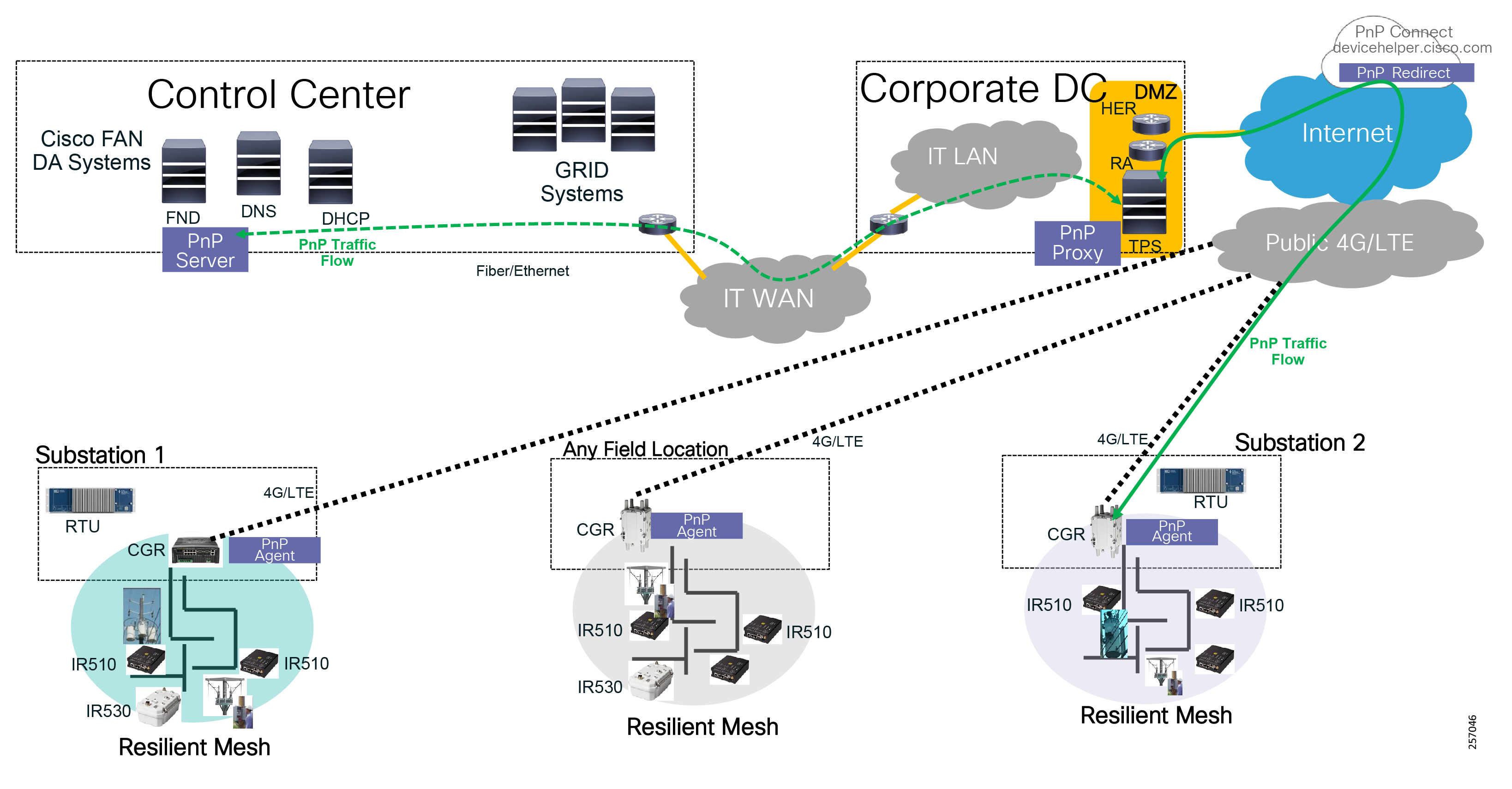
On the other hand, Private Cellular Services uses a customer APN name that needs to be configured on the FAR modem so that the modem can join the correct cellular network. Since the device startup configuration needs to be empty, the APN name needs to be configured using global configuration mode onto the modem configuration, not onto the router configuration, which stays permanent even during device reboot.
Figure 104 FAR ZTD 2.0 over Private APN without Internet Service
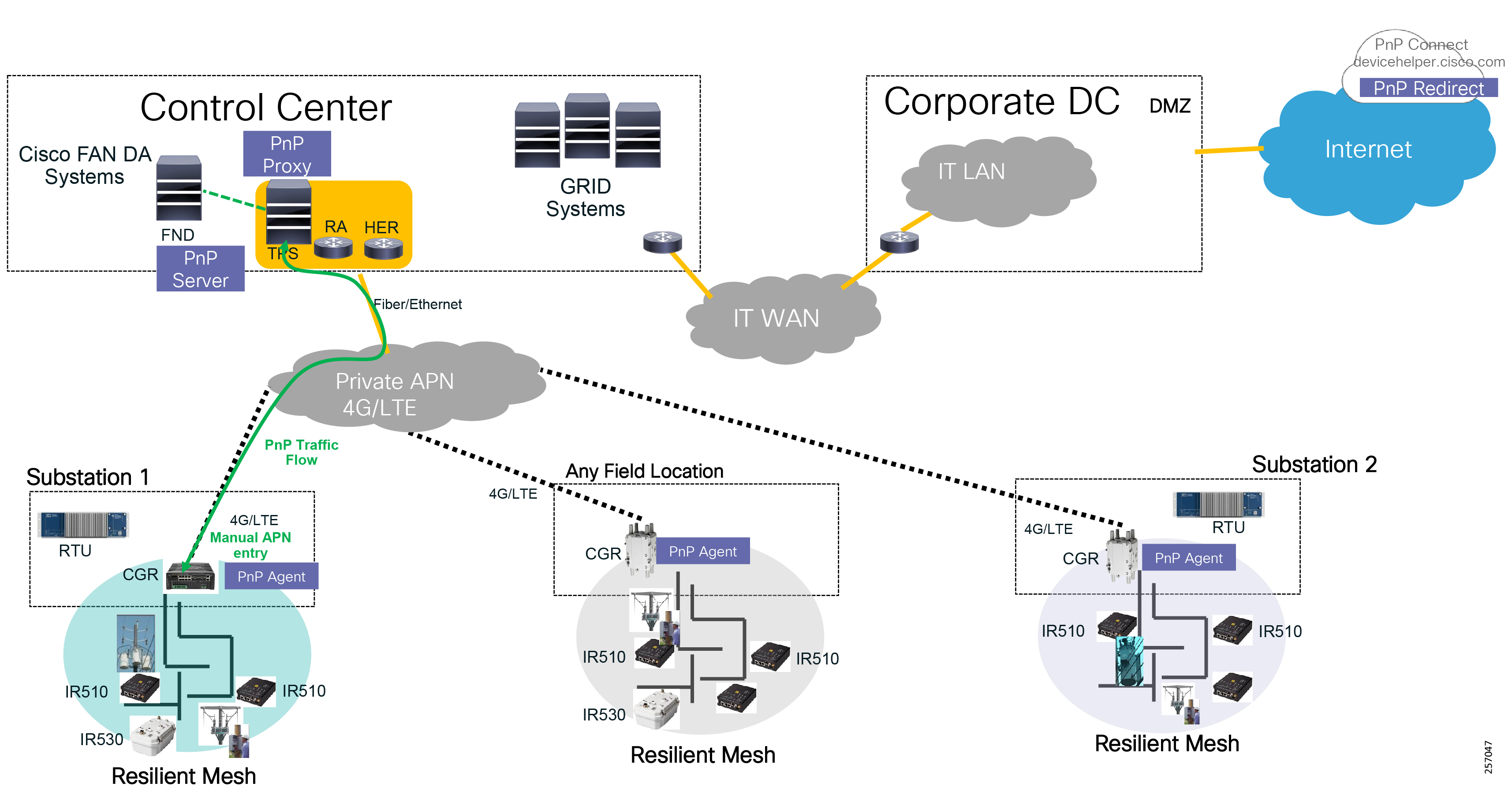
When the Private APN service is provisioned with Internet Service, then customers can use the PnP Connect option to redirect the FAR devices to the TPS server located in the Control Center DMZ. The modem, in this case, still needs to be configured with the custom APN name that was defined when the cellular service order was placed.
Using PnP Connect simplifies the user router configuration, which can be done during Staging or at the final destination as well.
Figure 105 FAR ZTD 2.0 over Private APN with Internet Service
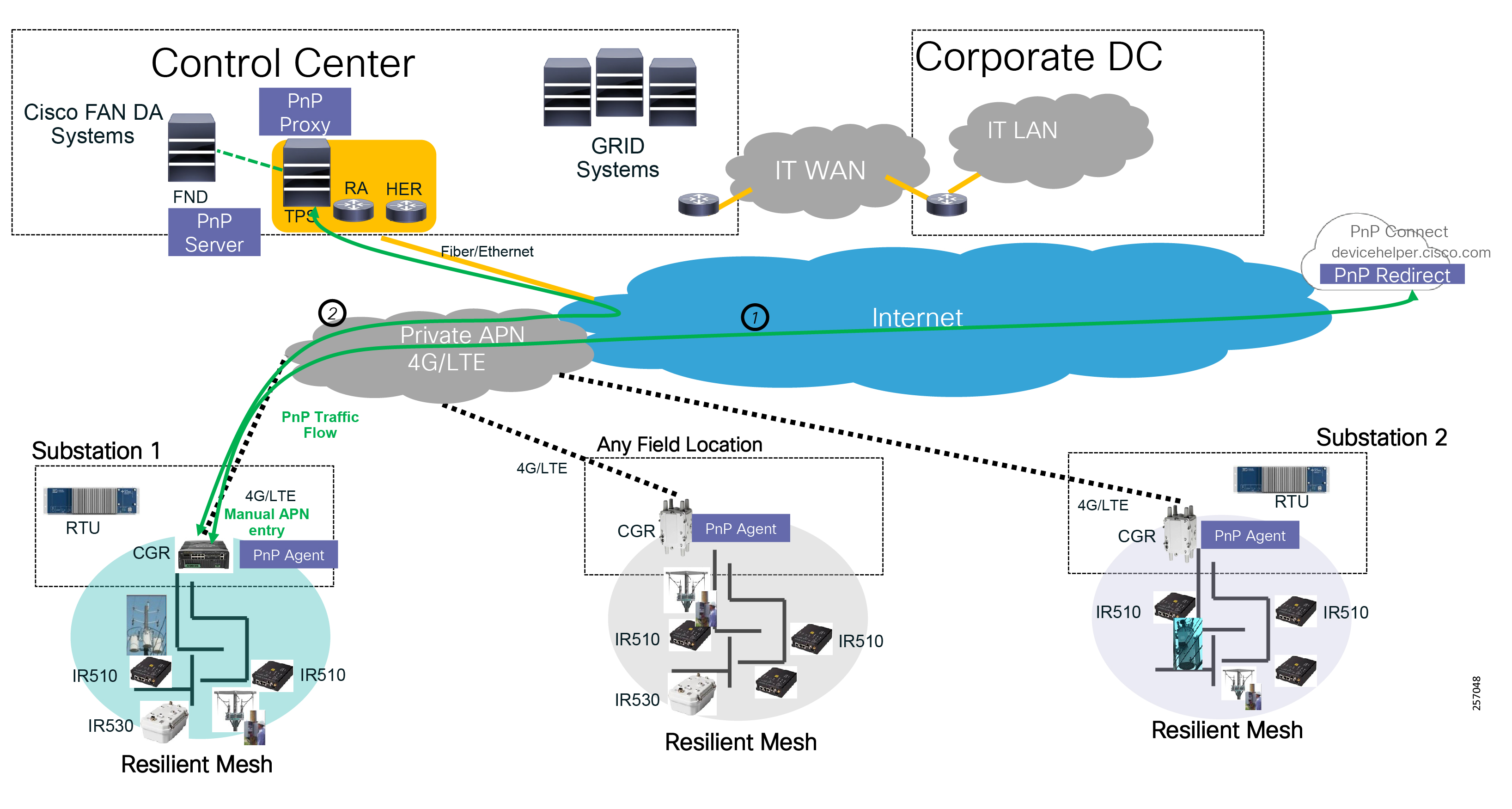
If the Private APN is provisioned without internet services, customers can either manually configure the PnP Server information on the remote device or use the PnP DNS assist. When provisioning the Cellular services, the customer will configure the APN services to use their own DNS servers and create name records that resolve to the TPS server IP address.
|
|
|
|
|
|
|
Note: The device startup configuration must be empty in NVRAM for the PnP process to start. Also, because no startup configuration exists, the CGR router software image must be installed with a specific parameter that gets saved with the boot image name into the Rommon Boot variable instead of the startup configuration file.
For more information, please read the following documentation:
■![]() https://www.cisco.com/c/en/us/td/docs/routers/access/800/829/15-7-3M1-Release-Note.html
https://www.cisco.com/c/en/us/td/docs/routers/access/800/829/15-7-3M1-Release-Note.html
Note: For more information on the Cisco Plug and Plug Solution, please refer to the following URL:
■![]() https://developer.cisco.com/docs/network-plug-n-play/#!network-plug-and-play
https://developer.cisco.com/docs/network-plug-n-play/#!network-plug-and-play
Verizon Cellular service supports Dual APN configuration (also referred to as Split Data Routing) where customers could use the Public APN for device onboarding ZTD 2.0. During the device onboarding, the second Private APN can be configured eliminating the need for manual APN name configuration. Once the device is onboarded and managed by FND, customers could disable the Public APN for improved security.
Note: For more information on Cisco and Verizon Dual APN configuration guide, please refer to the following URL:
■![]() https://www.cisco.com/c/dam/en/us/td/docs/routers/access/interfaces/software/deployment/guide/guide-061217.pdf
https://www.cisco.com/c/dam/en/us/td/docs/routers/access/interfaces/software/deployment/guide/guide-061217.pdf
By automating the entire process, customers have the option to not use a staging facility; that reduces installation duration and cost by provisioning the devices at their final destination, as depicted in Figure 106.
Figure 106 Device Provisioning using ZTD 2.0 (PnP)
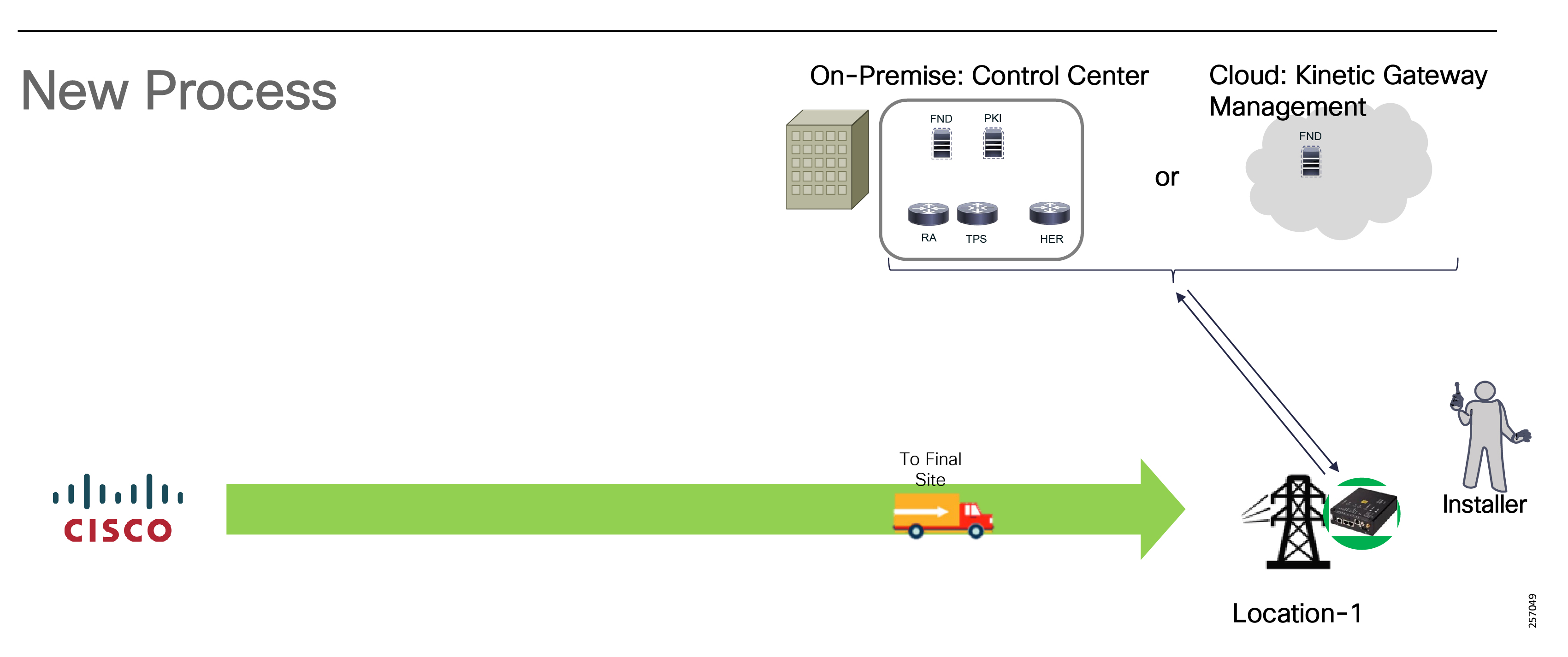
Note: It is highly recommended that customers test the process few times before mass deploying all the FAR routers during deployment phase.
Field Device (FD) Device Onboarding using ZTD 1.0 (Manual Bootstrapping)
Figure 107 FD Device Onboarding using ZTD 1.0
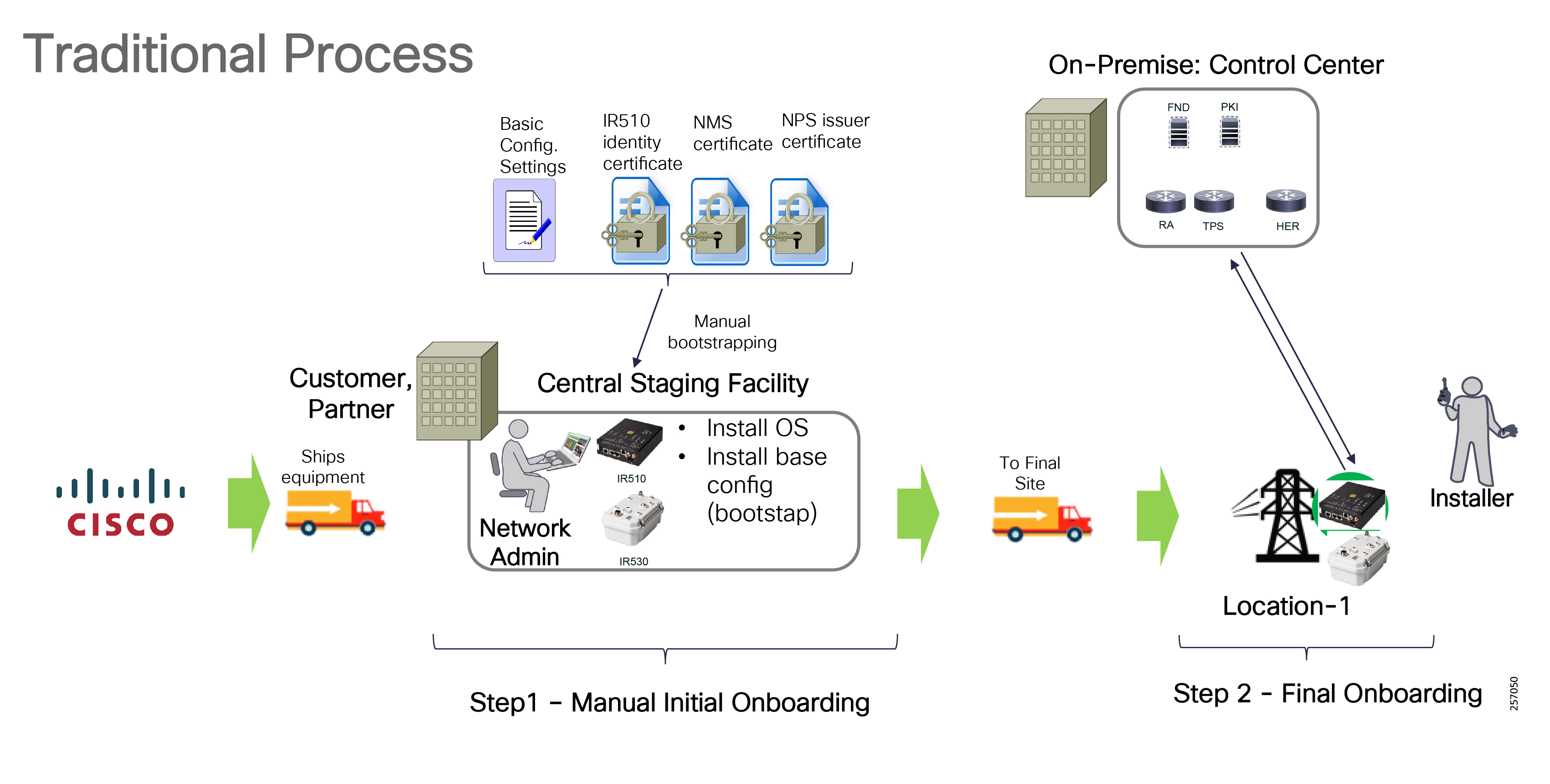
IR510 DA Gateways can be provisioned using two methods: the original method in which the devices must have three certificates installed (utility device identity, etc.) on the IR510 together with the basic RF configuration, sometimes referred to as the manufacturing configuration and the newest method, which is described in the next section.
In the original method, since the certificates are already provisioned, no certificate enrollment takes place, only device authentication and authorization in order to join the mesh network. The last step after the device joins the network is to register itself with FNDS via CSMP protocol and retrieve the final configuration from the FND repository. This method does not support certificate bootstrapping and re-enrollment. For a successful implementation, it is highly recommended that FDs are tested at the staging location before they are deployed since the chance exists that a device won't join the mesh if it has the wrong certificate information.
FD Certificate Enrollment using EST
The newest method, which is part of the Resilient Mesh solution, addresses the above limitations by allowing FDs to perform certificate enrollment to receive a new utility device certificate and renew certificates about to expire. With FND 4.3 and Mesh 6.0, the DA Gateways can take advantage of the embedded Cisco SUDI certificate to start the IEEE 802.1x authentication process to join the mesh and communicate with a new Enrollment over Secure Transport (EST) RA component that runs on FND. EST RA acts was a proxy between the FDs and PKI infrastructure and AAA Server to authenticate, authorize, and enroll the FDs with the Utility's certificate infrastructure in order for them to fully join the mesh network. The device enrollment is done using EST (RFC 7030) over a CoAP/DTLS session. Figure 108 depicts the process. This greatly simplifies the device certificate management process.
Note: The EST RA functionality is enabled by default on FND, but it can also be deployed on an external server running Linux OS.
Figure 108 IR510/IR530 New Enrollment Process
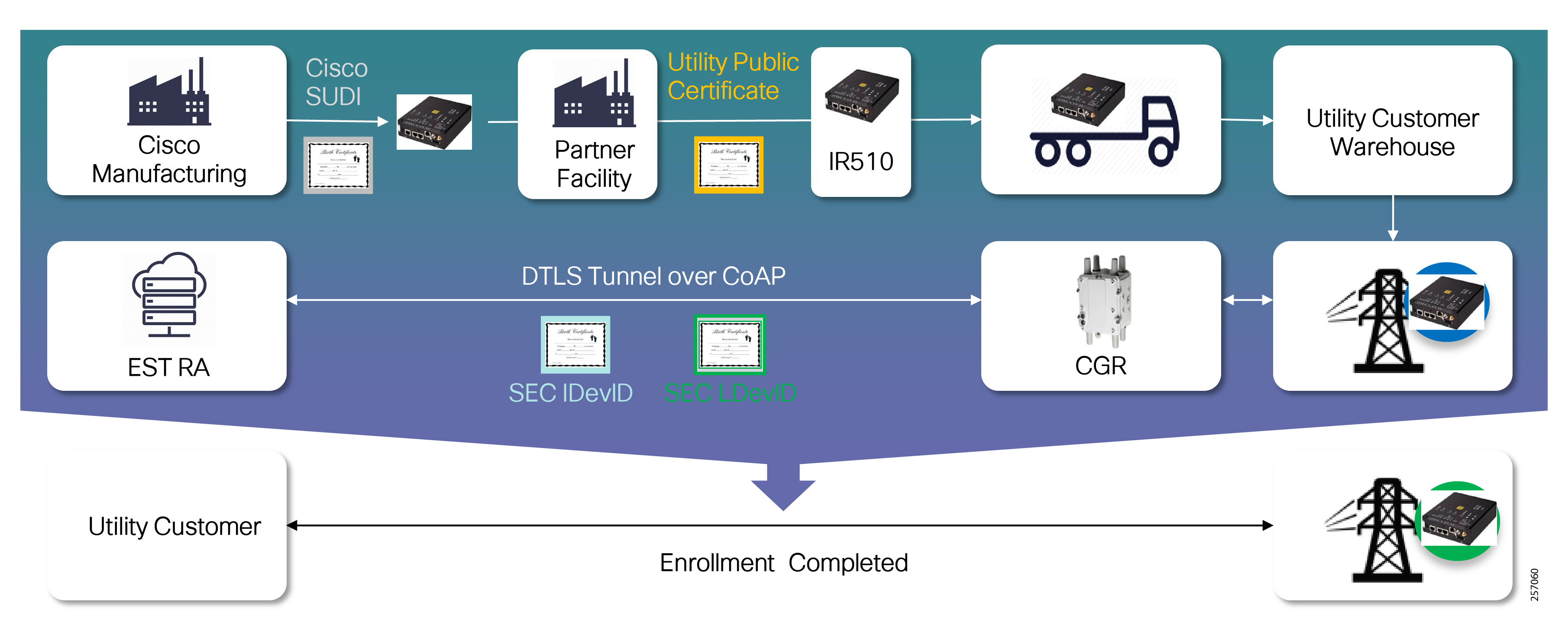
The Cisco SUDI certificates are installed during the manufacturing process. At staging, only the Utility Trust Anchor certificate (FND RA public certificate) together with basic RF configuration (SSID, etc) needs to be provisioned on the Field Devices.
Figure 109 FD Certificate Enrollment using EST Overview

Note: For additional details about the Control Center Network Management design considerations, refer to the Cisco FAN Head-End Implementation Guide at the following URL:
■![]() https://salesconnect.cisco.com/open.html?c=db570d3f-3212-4659-a306-5f65aeab862b
https://salesconnect.cisco.com/open.html?c=db570d3f-3212-4659-a306-5f65aeab862b
Once the devices registration is successful with FND, the device will receive its full configuration.
Cellular FAN DA Solution Devices Onboarding Overview
Figure 110 Cellular Gateways Onboarding Process
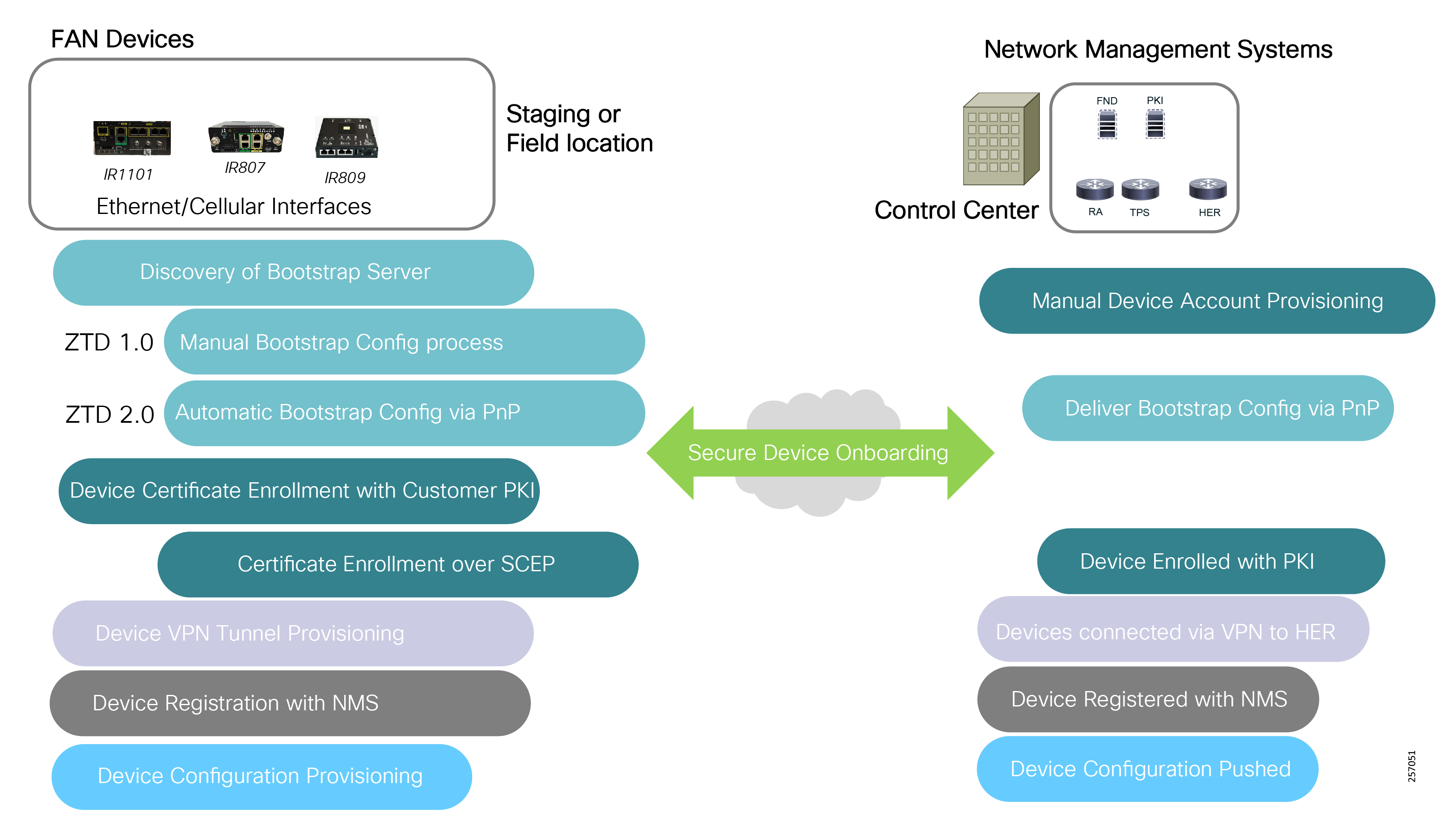
Today, the FAN DA Cellular solution supports the device onboarding methods shown in Table 51:
|
|
|
|
|
The FAN DA Cellular product can be managed On-Premise with two different management systems: Field Network Director (FND) or Cisco DNA Center (DNAC). FND is the preferred NMS for Cisco FAN DA. Cisco DNAC could be used in customer accounts where the utility enterprise IT team is already using DNAC for the enterprise network and would like to maintain the same look and feel for the OT network.
Cisco also offers a cloud-based gateway management solution called Cisco Kinetic Gateway Management (GMM) for customers that prefer a subscription model.
■![]() Cisco Field Network Director (FND) Overview:
Cisco Field Network Director (FND) Overview:
–![]() https://www.cisco.com/c/en/us/products/cloud-systems-management/iot-field-network-director/index.htmlCisco DNA Center Overview
https://www.cisco.com/c/en/us/products/cloud-systems-management/iot-field-network-director/index.htmlCisco DNA Center Overview
–![]() https://www.cisco.com/c/en/us/products/cloud-systems-management/dna-center/index.html
https://www.cisco.com/c/en/us/products/cloud-systems-management/dna-center/index.html
■![]() Cisco Kinetic Gateway Management (Cloud Service):
Cisco Kinetic Gateway Management (Cloud Service):
–![]() https://developer.cisco.com/docs/kinetic/ - !gmm-overview
https://developer.cisco.com/docs/kinetic/ - !gmm-overview
DA Cellular Gateway Device Onboarding using ZTD 1.0 (Manual Bootstrapping)
The device onboarding process for Cellular Gateway products is similar to the Unlicensed 900 MHz FAN solution described in Field Area Routers (FAR) Device Onboarding using ZTD 1.0 (Manual Bootstrapping).
The main differences between the products are the cellular interface naming:
■![]() IR1101 format is: interface Cellular 0/1/0 for SIM0 slot or Cellular 0/1/1 for SIM1 slot
IR1101 format is: interface Cellular 0/1/0 for SIM0 slot or Cellular 0/1/1 for SIM1 slot
■![]() IR1101 expansion module: interface Cellular 0/2/0 for SIM0 and Cellular 0/2/1 for SIM1 slot
IR1101 expansion module: interface Cellular 0/2/0 for SIM0 and Cellular 0/2/1 for SIM1 slot
■![]() IR807 format is: interface Cellular 0
IR807 format is: interface Cellular 0
■![]() IR809 format is: interface Cellular 0
IR809 format is: interface Cellular 0
DA Cellular Gateway Device Onboarding using ZTD 2.0 (PnP)
The preferred method for provisioning cellular products is the ZTD 2.0 because it simplifies deployment and allows for a large number of devices to be provisioned automatically. The same process described in Automatic Device Bootstrapping Configuration using PnP Connect applies to IR1101, IR807, and IR809.
Figure 111 Device Onboarding using ZTD 2.0 (PnP)
Devices can be onboarded at the staging facility or final destination. Provisioning devices at the final destination reduces costs associated with the staging facility, additional equipment shipments, and resource travel. It improves solution security by removing the dependency on good third-party security policies. On the other hand, this new type of deployment requires thorough testing during the Pre-deployment phase to ensure that all components work as expected to avoid additional site visits. When devices are provisioned over cellular backhaul connectivity, the solution depends on the Service Provider service reliability.
Note: It is highly recommended that customers test the process few times before mass deploying all the DA Cellular Gateways during the deployment phase in order to avoid additional truck rolls post deployment.
FAN Device Software Management
FND manages the firmware upgrades for the FAR devices, DA Gateways, and Range Extenders. The first stage of the upgrade process is firmware upload to local device storage. Upgrades can be scheduled so that they can be done during times where the grid network activity is slow. The process can be canceled or paused at any time.
Firmware upgrades can be done per groups of devices and for special cases per device. FND will first check if the targeted devices have the software firmware on flash so that it reduces the WAN bandwidth utilization. Upgrades are done in increments of 16 devices at the same time from a particular group. Since flash space is limited, the FND will delete the unused software and, if there isn't enough space, it will notify the administrator that the device requires manual upgrade intervention.
Depending on the FAR backhaul bandwidth, the software load stage to the FAR could take anywhere from a few minutes to few hours. The length of this process is also influenced by the number of Field Devices and the Control Center WAN interface bandwidth oversubscription ratio to the number of substations. To optimize the upload stage, firmware can be delivered over IPv6 multicast to optimize the mesh bandwidth usage for a large group of devices. Unicast is also supported. Based on the number of targeted devices, the FND will calculate whether multicast or unicast are most efficient at transmitting the firmware.
Mesh devices have flash storage divided in the Uploading slot, Running slot, and Back-up slot. When FND is uploading a new firmware image, it will overwrite the Uploading slot information. The image is uploaded block by block and only missing blocks are retransmitted.
With the new Resilient Mesh 6.0 software, the mesh uses the Cascade Firmware Upgrade feature to further improve the software delivery process and reduce the bandwidth utilization of the mesh. The firmware is reusing Multicast Protocol for Lossy Networks (MPL) RFC 7731, data and control messages with a slightly different behavior to improve functionality. Now retransmission take place between node and parents rather than between nodes and the FND. Mesh devices use ICMPv6 packets to carry the MPL request control messages that carry the seed ID and message bitmap and are sent to the neighbor IPv6 unicast link-local address instead of to the multicast link-local address (e.g. FC02::FC). The multicast messages are sent in the broadcast channel based on the common broadcast PAN scheduler.
The performance or the duration of the firmware delivery is affected by the number of forward density and the numbers of hops to a destination. Higher density within an area also improves the source multicast input rate into mesh. The mesh number of nodes: small, large; number of hops and the FND input rate.
Administrators can control the source multicast input rate as Fast, Medium, and Slow into the mesh on the FND management servers. The MPL messages are marked with a QoS DSCP value of 0 (low priority).
Figure 112 Mesh Cascade Firmware Update Overview
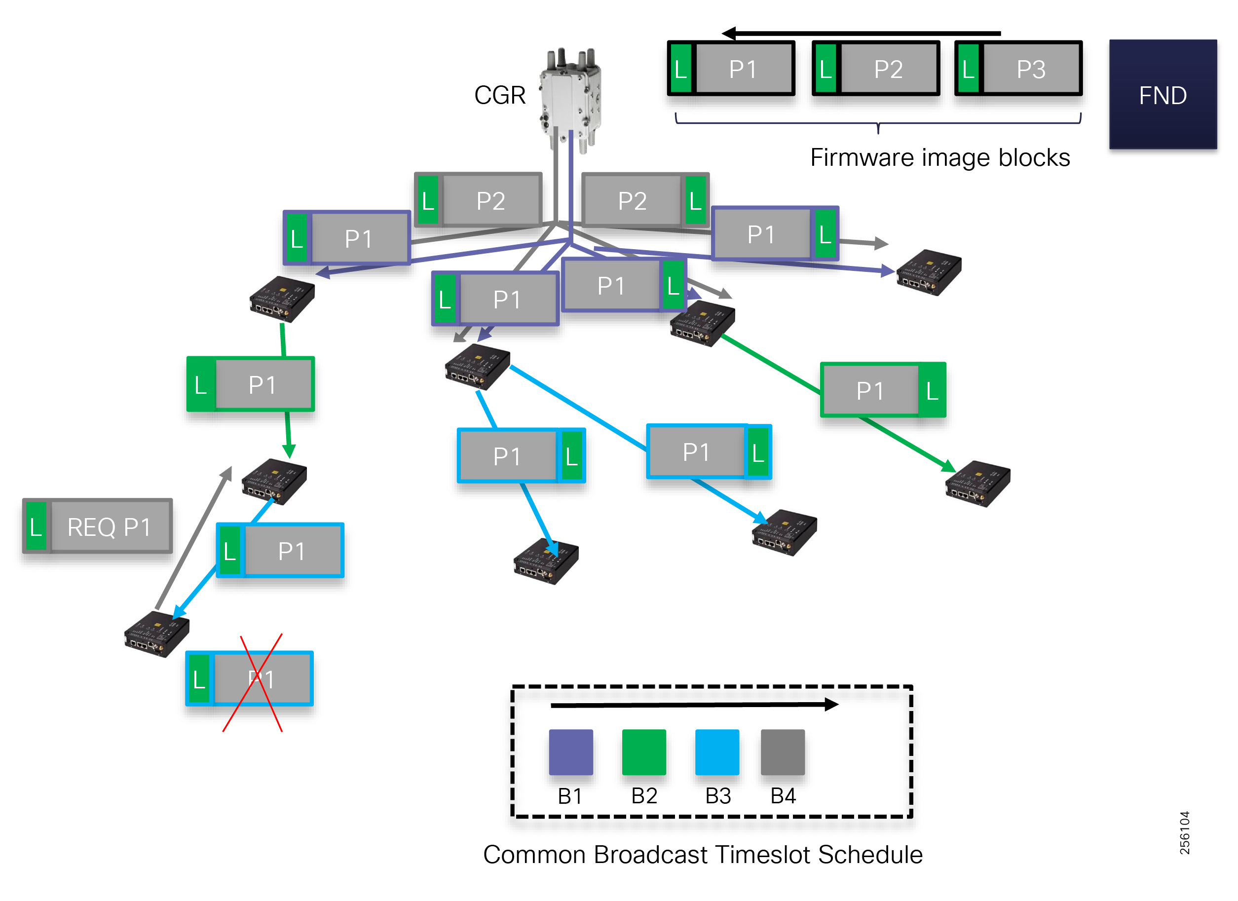
Figure 112 shows an example of how the FD image firmware is split in blocks that are encapsulated in IPv6 packets. The MPL messages are low priority and are transmitted in the Mesh Broadcast time slots. Each time slot is depicted by a different color to show how packets are transmitted over time. When a node has not received the entire firmware image blocks, it can request its parents to retransmit the missing blocks.
Once all the firmware image blocks are received, the device image is loaded in the running slot and the device is rebooted.
WAN Device Management
The HER devices use the traditional NMS protocols like SNMP to be monitored and managed. Customers can use the existing management tools to perform device management functions. For new deployments, Cisco Prime Infrastructure is an advanced management tool and can be used to manage the WAN infrastructure.
Note: Cisco Prime Infrastructure product overview. Refer to the following URL:
■![]() https://www.cisco.com/c/en/us/products/cloud-systems-management/prime-infrastructure/index.html
https://www.cisco.com/c/en/us/products/cloud-systems-management/prime-infrastructure/index.html
Edge Compute Software Management
Starting with FND 4.4, Edge Compute applications can be managed from a single GUI interface of the FND server. Customers can package their application in a Docker-style container and upload it to the FND for delivery and installation on the Field Device. FND uses an optimized process for software delivery similar to the FD firmware update.
Figure 113 Edge Compute Develop and Deployment Overview
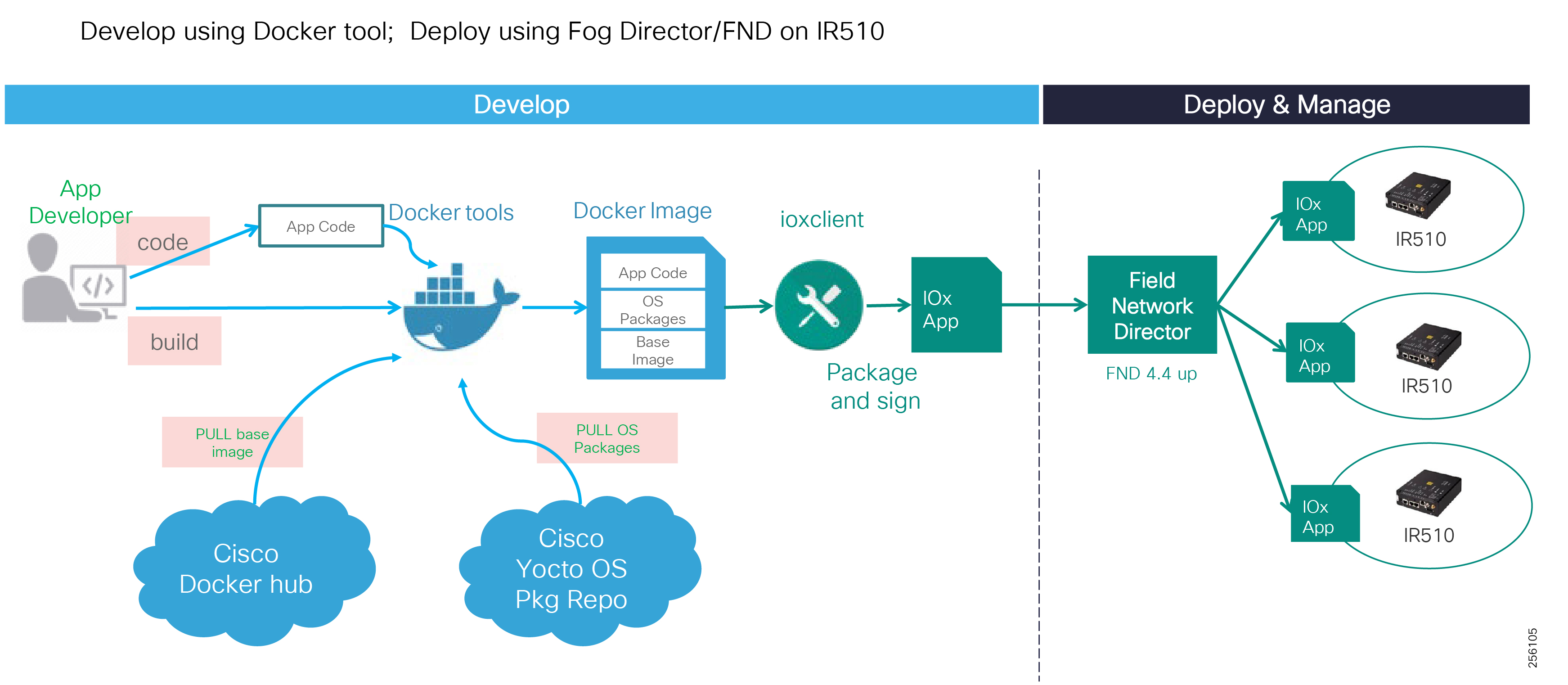
Network designers should work closely with the utility software development team or third-party software companies. Since the mesh bandwidth is valuable and limited, software developers should try to optimize the way the application and its library dependencies are packaged in the EC container. Avoid monolithic packaging because any changes will require the entire container to be re-deployed over the mesh, thereby consuming unnecessary bandwidth. A good container design should leverage the Docker's layering function and separate the elements that have a higher probability of changing. For example, the application code should be part of its own layer since software programmers most likely will release new software functionality more often than the application's library decencies updates. In addition, if the application requires multiple libraries like Java and Python and then separating each library in a layer would help with critical software patch releases.
Figure 114 FND EC Application Deployment
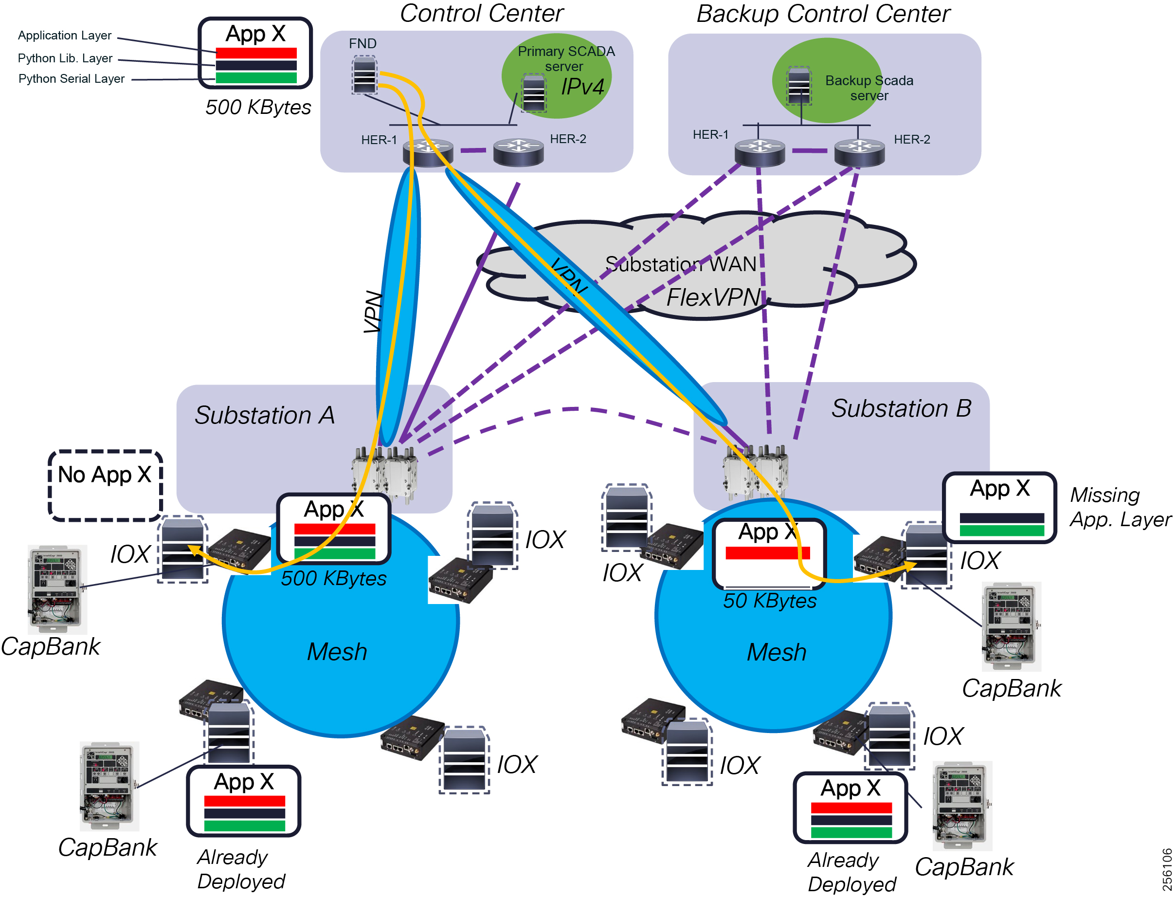
Administrators can use the FND's graphical statistic page to check the status of the application running state, device resource utilization, and troubleshoot any application crashes. Application and device log analysis was optimized so that administrators can remotely look at the most recent events or retrieve events based on a customized time period.
Figure 115 FND FD IOX Application Statistics
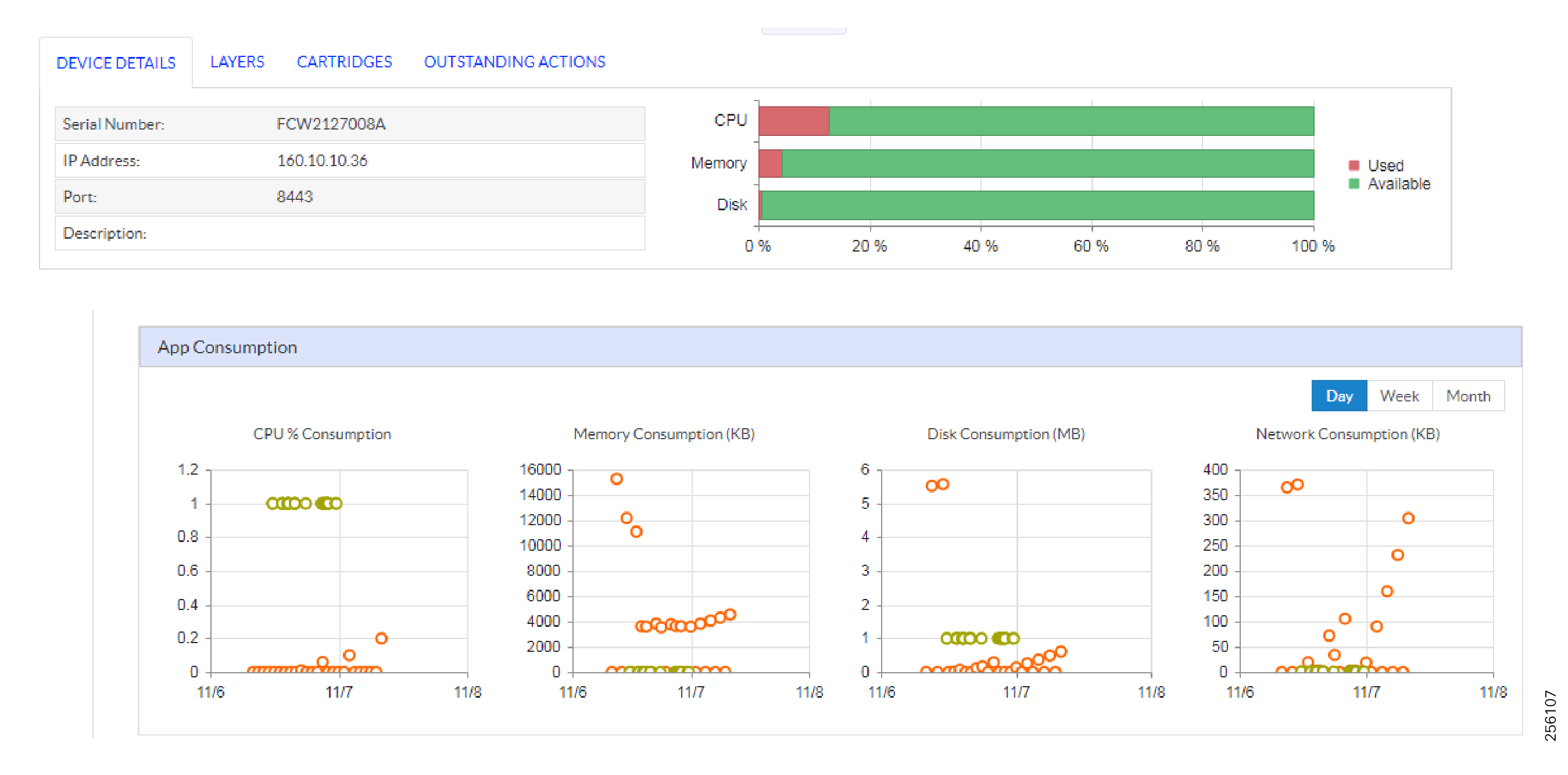
Device Work Order Ticket
FND has a built-in Work Order functionality so that only authorized Field Technicians can access the FAR and the FD Mesh devices. Cisco provides the IOT Device Manager (IOT-DM) graphical tool for local management of the mesh device using the out-of-band management Console or Ethernet port.
Figure 116 IoT Device Manager Graphical Interface
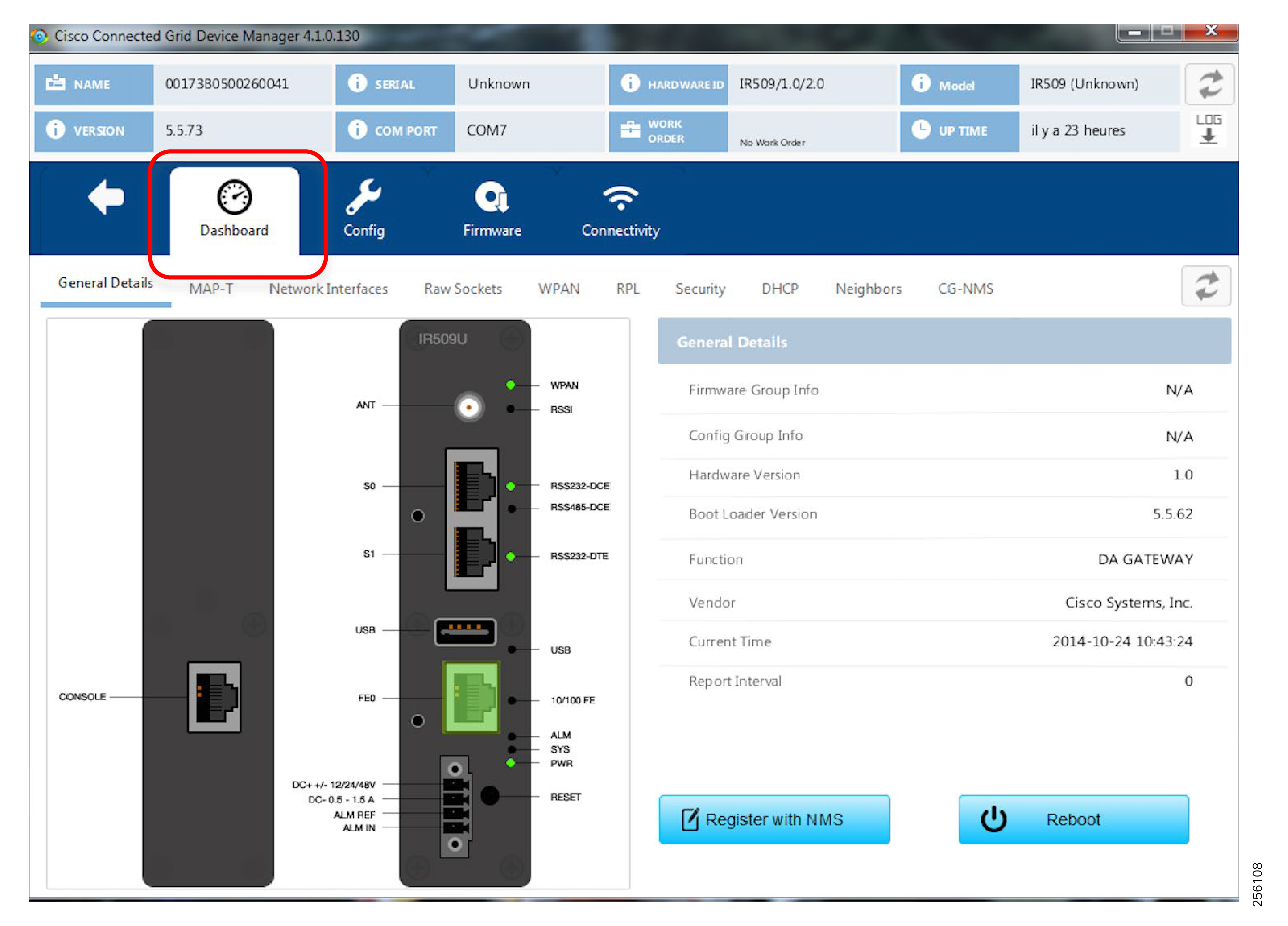
Access to these ports is restricted by enforcing network authentication and authorization for a period of time defined in the FND Work Order ticket form. The authentication is based on certificates and no user and password needs to be exchanged with the Field Technician, greatly increasing the solution security. Once the work order expires, the Field Technician laptop won't be able to access the Field Device even if there is physical access. A new work order ticket will need to be created by the System Operation personnel at the Control Center.
Figure 117 Work Order Process Flow
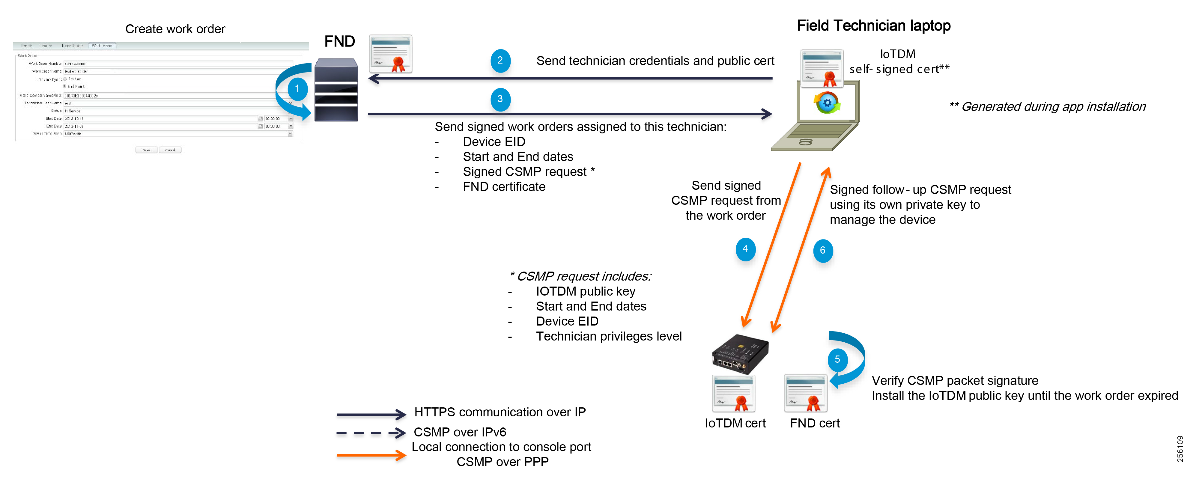
Field technicians can perform local troubleshooting and upload new firmware using the graphical IOT-DM tool.
Note: Cisco IOT-DM tool requires Windows 10 OS. Please refer to the following URL:
■![]() https://www.cisco.com/c/en/us/td/docs/routers/connectedgrid/iot_dm/guide/guide_5_0/b_iot-device-manager-5/b_iot-device-manager-5_chapter_00.html
https://www.cisco.com/c/en/us/td/docs/routers/connectedgrid/iot_dm/guide/guide_5_0/b_iot-device-manager-5/b_iot-device-manager-5_chapter_00.html
Network Availability and Resiliency
FAN Infrastructure Layer
The IEEE 802.15.4g supports only one coordinator per wireless mesh PAN. The FAR device acts as the PAN coordinator. In order to increase the network availability and the resiliency of the network and avoid Inter-PAN migration, Cisco has developed the High Availability feature. Customers can deploy FAR chassis WPAN module redundancy or FAR chassis redundancy based on the targeted network availability goals.
Note: The High Availability feature requires an external Ethernet cable between the redundant chassis.
In both implementation types, the WPAN modules work in an Active/Standby configuration. Only one WPAN, the Active WPAN module, sends and receives IEEE 802.15.4g frames. The Active WPAN synchronizes its state (Neighbor table, RPL, etc.) with the Standby WPAN over the FAR backplane when the two are installed in the same chassis or over a Layer 2 Ethernet link between the two chassis.
Figure 118 HA WPAN Deployment: Normal and Abnormal Conditions
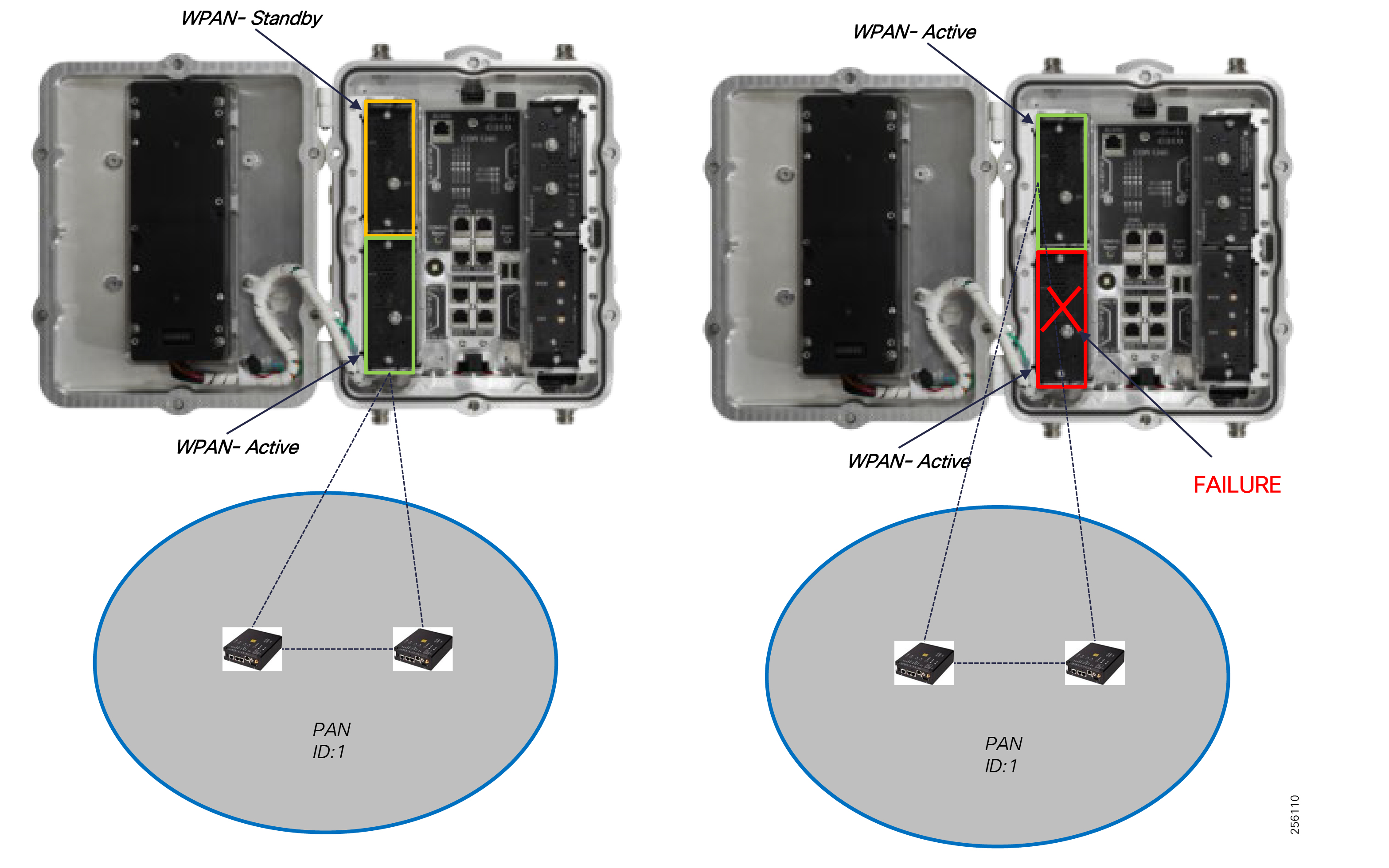
For WPAN HA configuration, the network recovery time is within a few seconds.
Figure 119 HA Chassis Deployment: Normal and Abnormal Conditions
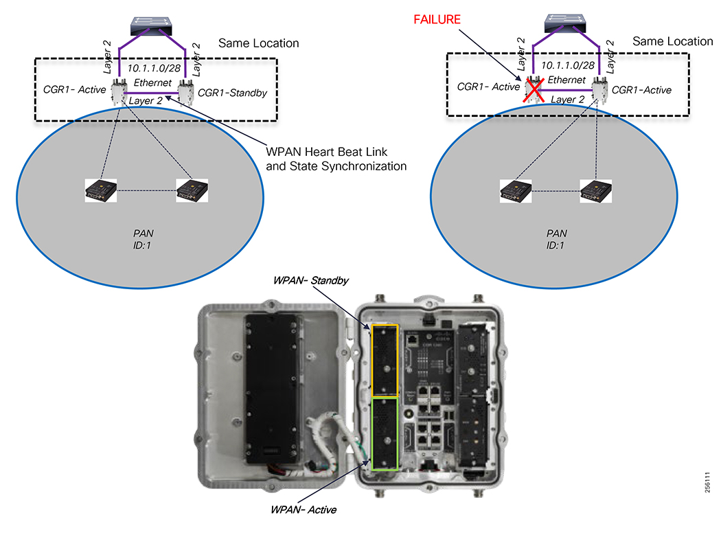
For Chassis HA, the recovery time is within a couple of minutes based on the failure detection timers.
For Highly Available environments, Cisco recommends customers deploy the chassis redundancy because it offers additional protection against failures.
|
|
|
|
|
|
||
|
|
||
|
|
||
|
|
||
|
|
To increase the overall PAN network availability, each node should have at least two upstream links to two diverse parents. Ideally, the higher the separation angle between the two links, the better so that a single obstruction will not affect both paths. In addition, the two upstream links should have similar characteristics in terms of performance and rank position within the RPL routing tree. This will help minimize the downstream tree topology changes during a link failure. In places where no redundancy exists, customer should consider installing additional Range Extenders (IR530) to increase the node network availability, as shown in Figure 120.
Figure 120 Upstream Link and Node Redundancy: Normal Conditions with Upstream Redundancy and Link & Node Failure
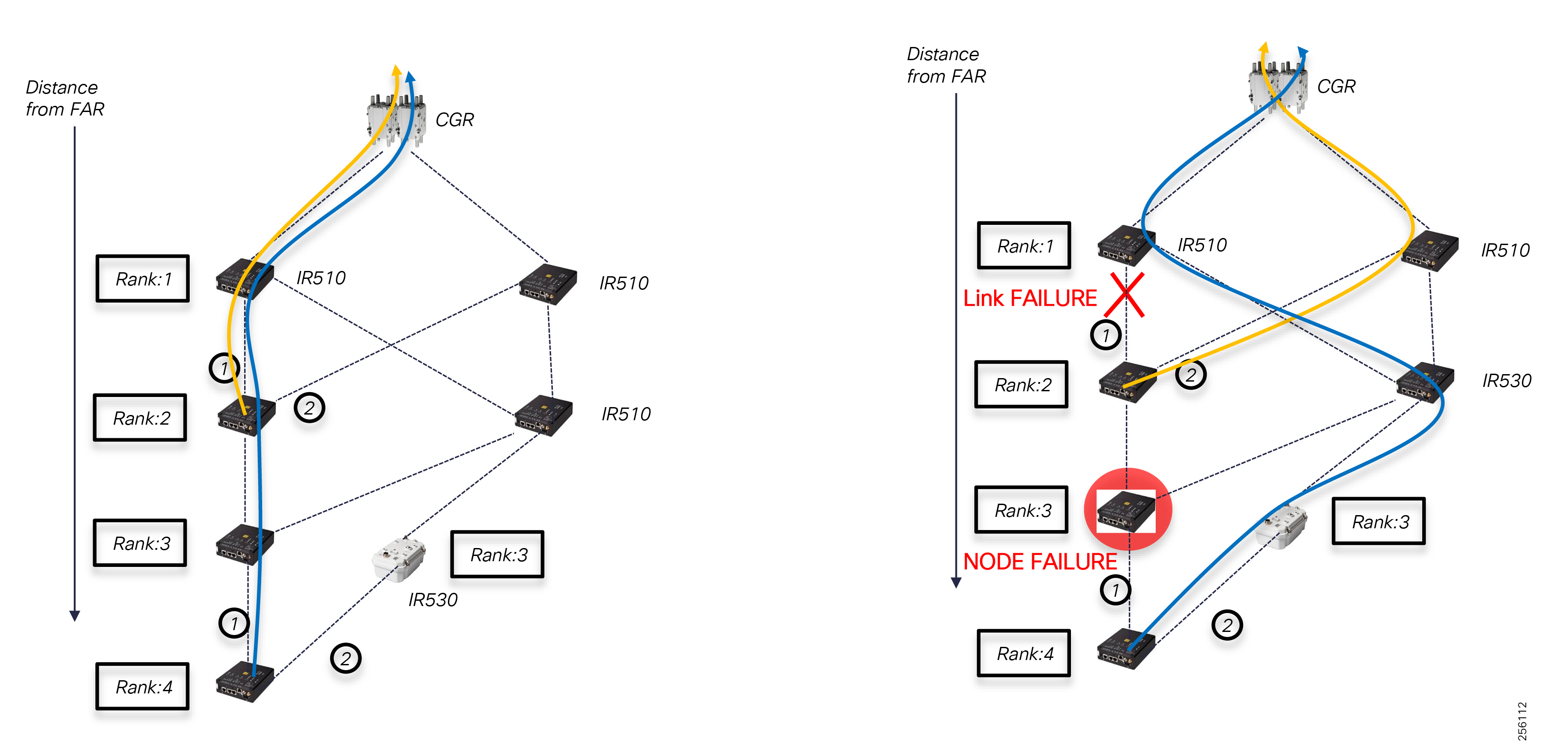
Customers should consider adding battery backup to the DA Gateway devices to increase the network uptime, especially during a distribution feeder power outage. The IR510 can be powered using DC Input voltage with a range from ± 9.5V to ± 60V. Depending on the geographical climate deployment area and the additional equipment that is installed in the enclosure housing, the IR510, customers should ensure proper spacing between equipment or consider additional ventilation options to stay within the IR510's thermal requirements for proper operations.
Note: The system shall operate in a thermal environment from -40 °C to 85 °C.
Figure 121 DA Gateway Battery Back-up Example
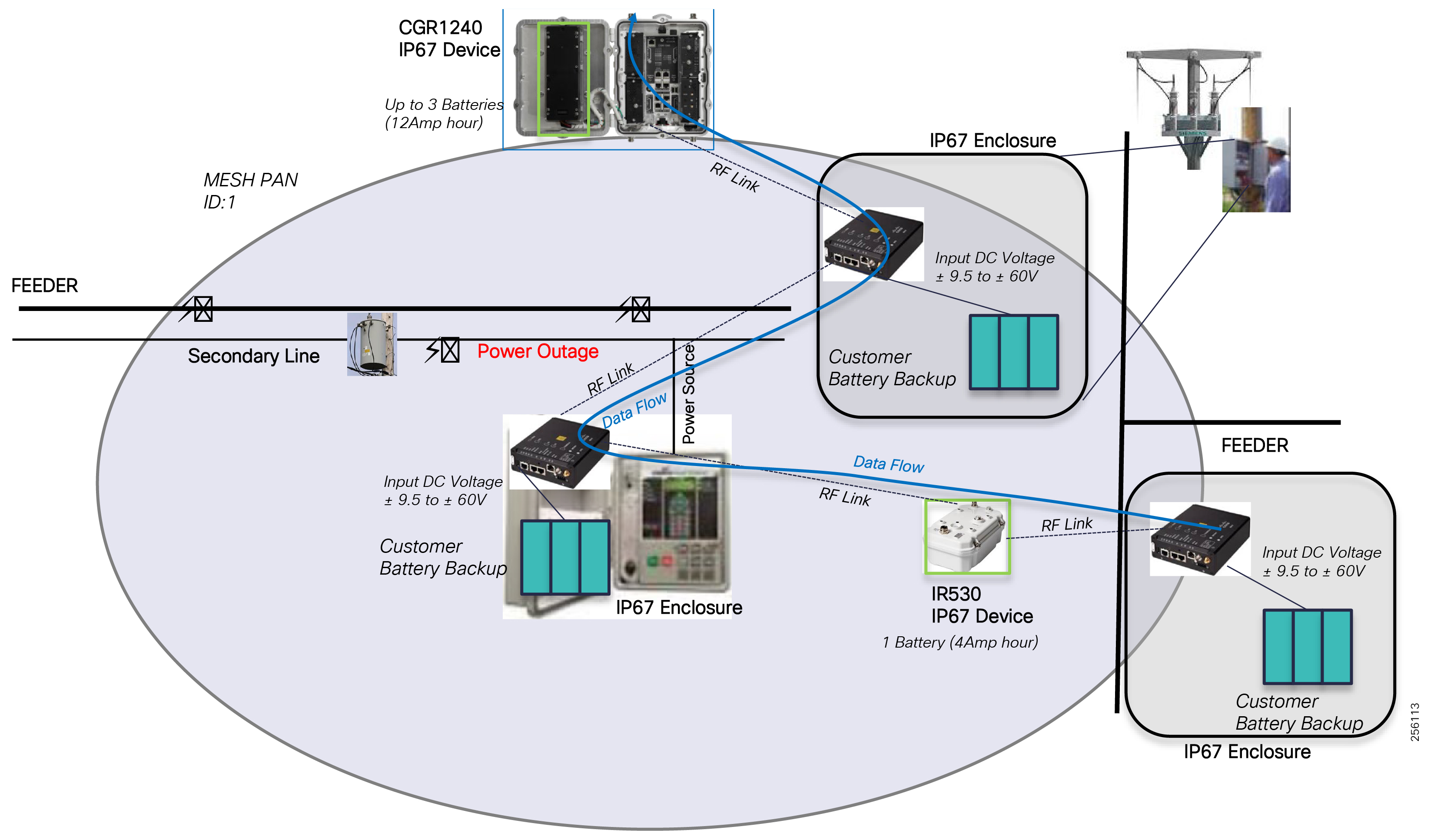
For customers that are looking to leverage a solar panel to charge the UPS battery attached to an IR510, the following data can be used as a reference guide for initial system planning to determine if the equipment location installation can provide enough solar energy to meet the system availability.
IR510 power usage depends on the radio transmission modulation, data rate, and transmitter duty cycle. For 50% duty cycles, the power usage is around 8W. Power usage increases when additional IOX applications are ran on the IR510. When IOX CPU utilization is at 50%, the power consumption will use an additional 4-5W.
Note: The power usage listed above are reference numbers for an ambient temperature of 77°F (25 °C). For precise numbers check the product data sheet.
For disaster recovery scenarios, when a wide PAN failure has occurred (for example, the mesh coordinator has failed), the DA Gateways can perform Inter-PAN migration as a gateway of last resort. This migration process is slow and depends on a number of factors:
■![]() Node cache knowledge of the adjacent PAN information
Node cache knowledge of the adjacent PAN information
■![]() Node security credential of the adjacent PAN
Node security credential of the adjacent PAN
■![]() Number of nodes that needs to perform Inter-PAN migration
Number of nodes that needs to perform Inter-PAN migration
■![]() The failed PAN ID topology (daisy-chained, etc)
The failed PAN ID topology (daisy-chained, etc)
Figure 122 Disaster Recovery via Inter-PAN Migration: Normal State and PAN ID 1 Failure
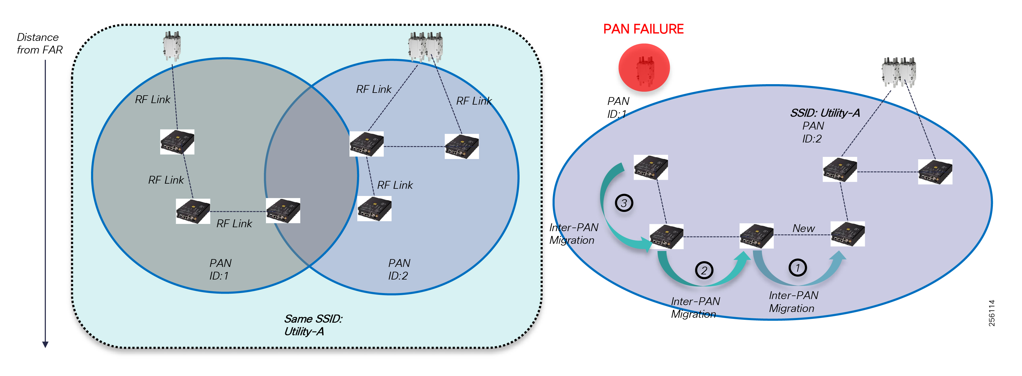
Note: In order for Inter-PAN Migration to work, both mesh PANs must be configured with the same SSID.
Inter-PAN migration design should be carefully analyzed as part of the PAN Capacity planning and the PAN targeted performance since traffic volume will increase based on the number of nodes that will migrate and the type of DA applications they support.
WAN Infrastructure Layer
FlexVPN can be deployed in a Highly Available configuration to increase network availability and resiliency over the WAN. To prevent hub failures, customers can deploy FlexVPN in a Multi-Hub Stateless Failover or Multi-Hub Resiliency topology within the same Control Center or across the Primary and Back-up Control Centers.
A FlexVPN with Stateless Failover design has two or more hubs routers configured in an active/standby HSRP configuration and the spoke devices. FAR routers are only configured with a single VPN tunnel to the HSRP Virtual IP address.
The Multi-Hub Resiliency design uses the spoke backup peer IKEv2 feature where the FAR routers are configured with multiple backup HER IP addresses and only establish one VPN tunnel to the primary HER device. If a failure occurs, the FAR router will establish a new VPN tunnel to the secondary or tertiary HER IP address.
■![]() Each HA design convergence can be lowered to a milliseconds or seconds range by using additional failure detection mechanisms like BFD or IPSLA at the expense of the WAN bandwidth utilization.
Each HA design convergence can be lowered to a milliseconds or seconds range by using additional failure detection mechanisms like BFD or IPSLA at the expense of the WAN bandwidth utilization.
■![]() Additional configuration enhancements can be done for designs with spoke with dual-tunnel configuration so that traffic is load-balanced across the two HERs.
Additional configuration enhancements can be done for designs with spoke with dual-tunnel configuration so that traffic is load-balanced across the two HERs.
If the Inter-PAN migration is desired and implemented, network administrators need to take into consideration the additional dynamic IPv6 host routes that are being learned by the FAR devices from the DA Gateways that join an adjacent PAN. The host route is inserted in the FAR routing table as a connected route, which will need to be advertised into the FlexVPN routing domain so that traffic from the Control Center can be routed toward the new FAR device.
Figure 123 PAN MAP-T Prefix Advertisement
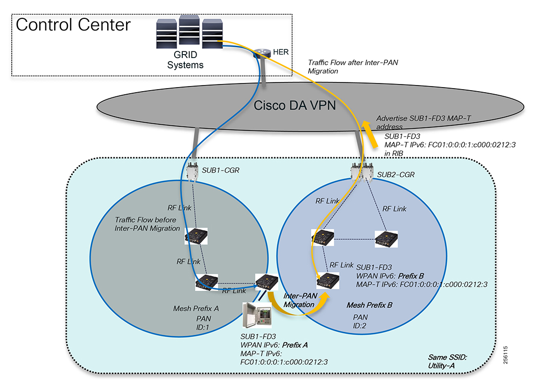
For Dual-Hub Resiliency, please refer to the following URL:
■![]() https://www.cisco.com/c/en/us/support/docs/security/flexvpn/118888-configure-flexvpn-00.html
https://www.cisco.com/c/en/us/support/docs/security/flexvpn/118888-configure-flexvpn-00.html
For the FlexVPN with IKEv2 Load-Balancing Cluster Configuration Guide, please refer to the following URL:
■![]() https://www.cisco.com/en/US/docs/ios-xml/ios/sec_conn_ike2vpn/configuration/15-2mt/sec-cfg-clb-supp.html
https://www.cisco.com/en/US/docs/ios-xml/ios/sec_conn_ike2vpn/configuration/15-2mt/sec-cfg-clb-supp.html
For Multi-Hub Resiliency with Spoke Dual Tunnel per WAN Transport Service, please refer to the following URL:
■![]() https://www.cisco.com/c/en/us/support/docs/security/flexvpn/116412-configure-flexvpn-00.html
https://www.cisco.com/c/en/us/support/docs/security/flexvpn/116412-configure-flexvpn-00.html
Headend Infrastructure Layer
The FND is a critical application for monitoring and managing a Distribution Grid communication infrastructure. The FND was designed with High Availability in mind and customers should deploy the management software in a redundant configuration to address the overall availability of system.
FND provides two main levels of HA: one for the front-end FND Server(s) and the other for the backend and database HA:
■![]() FND Server HA-This is achieved by connecting multiple FND servers to network load balancer. Traffic originating from the FAN network goes to the load balancer, which uses a round-robin protocol to distribute the load among the FND cluster servers.
FND Server HA-This is achieved by connecting multiple FND servers to network load balancer. Traffic originating from the FAN network goes to the load balancer, which uses a round-robin protocol to distribute the load among the FND cluster servers.
■![]() FND Database HA-This is achieved by configuring two FND Database servers: a primary server and a standby (or secondary) server. When the primary database receives new data, it sends a copy to the standby database. A separate system runs the Observer (the Observer can also run on the standby server), which is a program that monitors the FND Database servers. If the primary database fails, the Observer configures the standby server as the new primary database. FND Database HA works in single and cluster IoT FND server deployments.
FND Database HA-This is achieved by configuring two FND Database servers: a primary server and a standby (or secondary) server. When the primary database receives new data, it sends a copy to the standby database. A separate system runs the Observer (the Observer can also run on the standby server), which is a program that monitors the FND Database servers. If the primary database fails, the Observer configures the standby server as the new primary database. FND Database HA works in single and cluster IoT FND server deployments.
Figure 124 FAN Management System High Availability
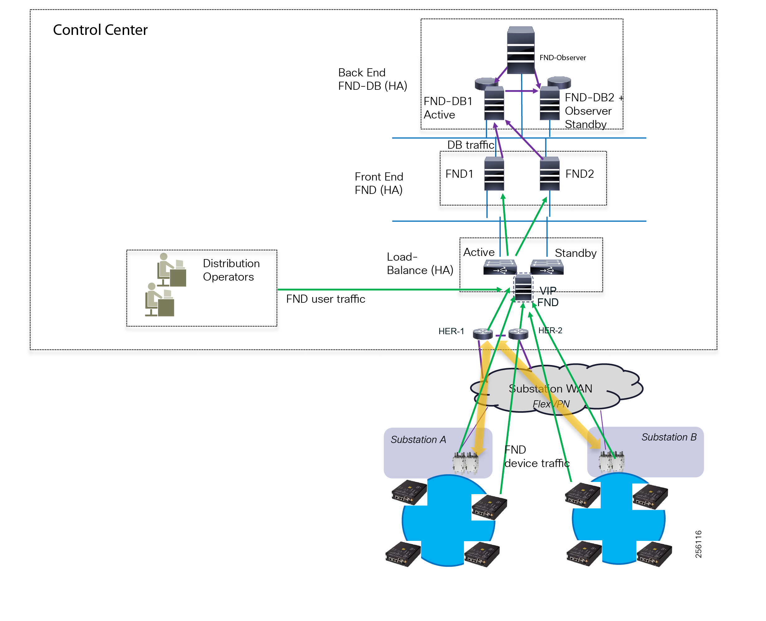
HA Guidelines and Limitations:
■![]() All FND nodes must on the same subnet
All FND nodes must on the same subnet
■![]() All FND nodes must run on similar hardware
All FND nodes must run on similar hardware
■![]() All IoT FND nodes must run the same software version
All IoT FND nodes must run the same software version
Note: The WAN and FAN devices can continue to operate for days during a catastrophic FND failure, but since FND maintains the security mesh keys for the FAN devices, customers must recover the FND server to avoid any disruption in the monitoring and controlling of the DA grid devices.
Cisco recommends customers consider deploying the FAN management infrastructure to a disaster recovery site as well; for example, Back-up Control Centers, especially for utilities located in areas open to natural disasters.
Besides the FND and FND Database, the other Headend Infrastructure components (Load-balancers, firewalls, DNS, DHCP, and Active Directory) should also be deployed in HA configuration to increase the availability of each service.
For the Cisco FND HA Installation Guide, please refer to the following URL:
■![]() https://www.cisco.com/c/en/us/td/docs/routers/connectedgrid/iot_fnd/install/4_1/iot_fnd_install_4_1/high_availability.html
https://www.cisco.com/c/en/us/td/docs/routers/connectedgrid/iot_fnd/install/4_1/iot_fnd_install_4_1/high_availability.html
For the Cisco Prime Network Register (CNR) HA - Administration Guide, please refer to the following URL:
■![]() https://www.cisco.com/c/en/us/td/docs/net_mgmt/prime/network_registrar/9-1/administration/guide/Admin-Guide/Admin-Guide_chapter_00.html
https://www.cisco.com/c/en/us/td/docs/net_mgmt/prime/network_registrar/9-1/administration/guide/Admin-Guide/Admin-Guide_chapter_00.html
For the Cisco Firewall HA Configuration Guide, please refer to the following URL:
■![]() https://www.cisco.com/c/en/us/td/docs/security/firepower/601/configuration/guide/fpmc-config-guide-v601/fpmc-config-guide-v601_chapter_01100110.pdf
https://www.cisco.com/c/en/us/td/docs/security/firepower/601/configuration/guide/fpmc-config-guide-v601/fpmc-config-guide-v601_chapter_01100110.pdf
For F5 Big IP Load Balancer Product Information, please refer to the following URL:
■![]() https://www.f5.com/services/resources/glossary/load-balancer
https://www.f5.com/services/resources/glossary/load-balancer
Equipment Mean Time Between Failures
Table 54 shows the Equipment Mean Time between Failures.
|
|
|
|
Network Scalability
FAN Infrastructure Layer
Customers can connect multiple grid devices to the DA Gateways based on the device communication interface.
|
|
|
|
|
Might require gender changer if grid devices are the same type |
|||
For more than one device, customers must use a layer 2 switch |
Currently, IR510 software version 6.0 supports up to 15 NAT44 entries; therefore, the number of IPv4 grid devices behind the IR510 varies and it's less than 254. This only applies when the application session towards the IPv4 grid device is initiated from a remote location and each IPv4 grid devices uses many unique ports.
Note: Out of the 15 NAT entries, three are used by the IOX module on the IR510
For DA deployments, this is not a problem since typically on an electrical feeder pole or underground cabinet, no more than two or three IPv4 grid devices exist
IPv6 grid devices do not have any restrictions. Cisco recommends customers make IPv6 support a requirement during the purchase evaluation process for electric grid equipment.
Note: The range extender (IR530) does not have any communication interface to connect grid devices
Each mesh device can maintain a large number of Layer 2 neighbors. A node maintains connectivity status up to four parents (upwards) and has no limit for downwards children when the Resilient Mesh operates in Non-Storing mode. When the mesh needs to support peer-to-peer communication, then the mesh must be configured for Storing Mode, which has a limit of the number of downward routes it can store.
|
|
|
|
|
|
||
|
|
||
|
|
The IR510 has a dedicated Edge Compute environment where customers can load grid applications to perform different local functions. The IR510 CPU is divided into CPU units that can be allocated and reserved to each application container.
|
|
|
|
|
|
|
|||
|
|
|||
|
|
|||
|
|
|||
|
|
|||
|
|
|||
|
|
Cisco CGR routers have four modular slots where customers can install a few combinations of modules based on the desired service.
|
|
|
|
Besides these modules, customers can attach serial as well as IP devices to the CGR.
|
|
|
|
Cisco CGR routers act as PAN Coordinators and maintain additional information compared to IR510 or IR530. The following are device software limits, including the maximum PAN size.
|
|
|
|
|
|
||
|
|
||
|
|
When designing a PAN size, network administrators need to account for all nodes during normal operations, but also for any potential nodes from nearby PANs that can perform Inter-PAN migration.
Initially, Edge Compute was implemented in the CGR routers using the native hardware. Since CGR routers act as aggregation devices, the onboard resources were not sufficient for today's edge process requirements. For small application and low resource utilizations, customers can still leverage the native IOx functionality. Recently, Cisco has developed a dedicated Edge Compute module called Cisco Server Module (CSM) that customers can install in one of the CGR router slots.
The CGR onboard IOx resources should be disabled and allocated 100% to IOS when a CSM module is installed.
For the Cisco CGR CGM Module Data Sheet, please refer to the following URL:
■![]() https://www.cisco.com/c/en/us/products/collateral/routers/1000-series-connected-grid-routers/datasheet-c78-739683.html
https://www.cisco.com/c/en/us/products/collateral/routers/1000-series-connected-grid-routers/datasheet-c78-739683.html
For additional Edge Compute resources, especially for large Edge Compute deployments, customers can deploy one or more IC3000 hardened server appliances within the substation network.
|
|
|
|
|
|
|
|||
|
|
|||
|
|
|||
|
|
|||
|
|
For the Cisco IC3000 Appliance Data Sheet, please refer to the following URL:
■![]() https://www.cisco.com/c/en/us/products/collateral/routers/3000-series-industrial-compute-gateways/datasheet-c78-741204.html
https://www.cisco.com/c/en/us/products/collateral/routers/3000-series-industrial-compute-gateways/datasheet-c78-741204.html
For the Cisco IOx Product Matrix, please refer to the following URL:
■![]() https://developer.cisco.com/docs/iox/ - !platform-support-matrix/platform-support-matrix
https://developer.cisco.com/docs/iox/ - !platform-support-matrix/platform-support-matrix
WAN Infrastructure Layer
FAR routers in the substation establish VPN tunnels with the HER devices in the Control Centers. Typically, only a pair of FAR devices is installed in the substation yard in a HA configuration.
Additional FAR devices or pair of devices can be installed within the same substation yard, but additional RF consideration must be taken into account that could have a negative impact on network performance. This topic is further explained in RF Design Considerations.
Depending on the WAN design solution, the active CGR router initiates one or multiple FlexVPN tunnels based on the utility Control Centers and Disaster Recovery locations. A network administrator has no limitations to take into consideration from a VPN tunnel scaling prospective, nor from a packet-forwarding rate because maximum Mesh radio physical interfaces rate of 1.2Mbps is much less than the FAR WAN interfaces when connected via an Ethernet interface 10, 100, or 1000Mbps.
The scaling consideration come into place for deployments with a large number of substations where the HER device (FlexVPN server) needs to aggregate lots of VPN tunnels. The HER maximum of tunnels is greatly affected by how many protocols the device must maintain besides the VPN control plane. GRE, dynamic routing protocols, aggressive routing protocol timers, and security services all reduce the maximum number of tunnels support on a HER device.
|
|
|
|
|
|
|
Headend Infrastructure Layer
The FND can support a large number of devices as listed in Table 64 and Table 65:
|
|
|
|
|
|
|
|
|
|
|
|
Network Flexibility
FAN Infrastructure Layer
The Cisco Resilient Mesh solution can support any type of network topology. The number of nodes, their location and each node RF coverage will dictate how the topology will look like. A node supports point-to-point and point-to-multipoint connectivity to other adjacent nodes. If multiple nodes share the same RF signal propagation area, then they can form a hub-and-spoke or star topology.
Figure 125 Basic Network Topology
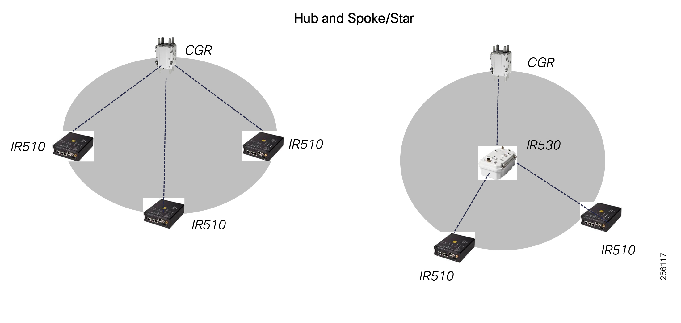
The network can be extended beyond one RF area by using composite network topologies like daisy chain, tree, or cluster tree topologies that cover larger distances.
Figure 126 Extended Network Topologies
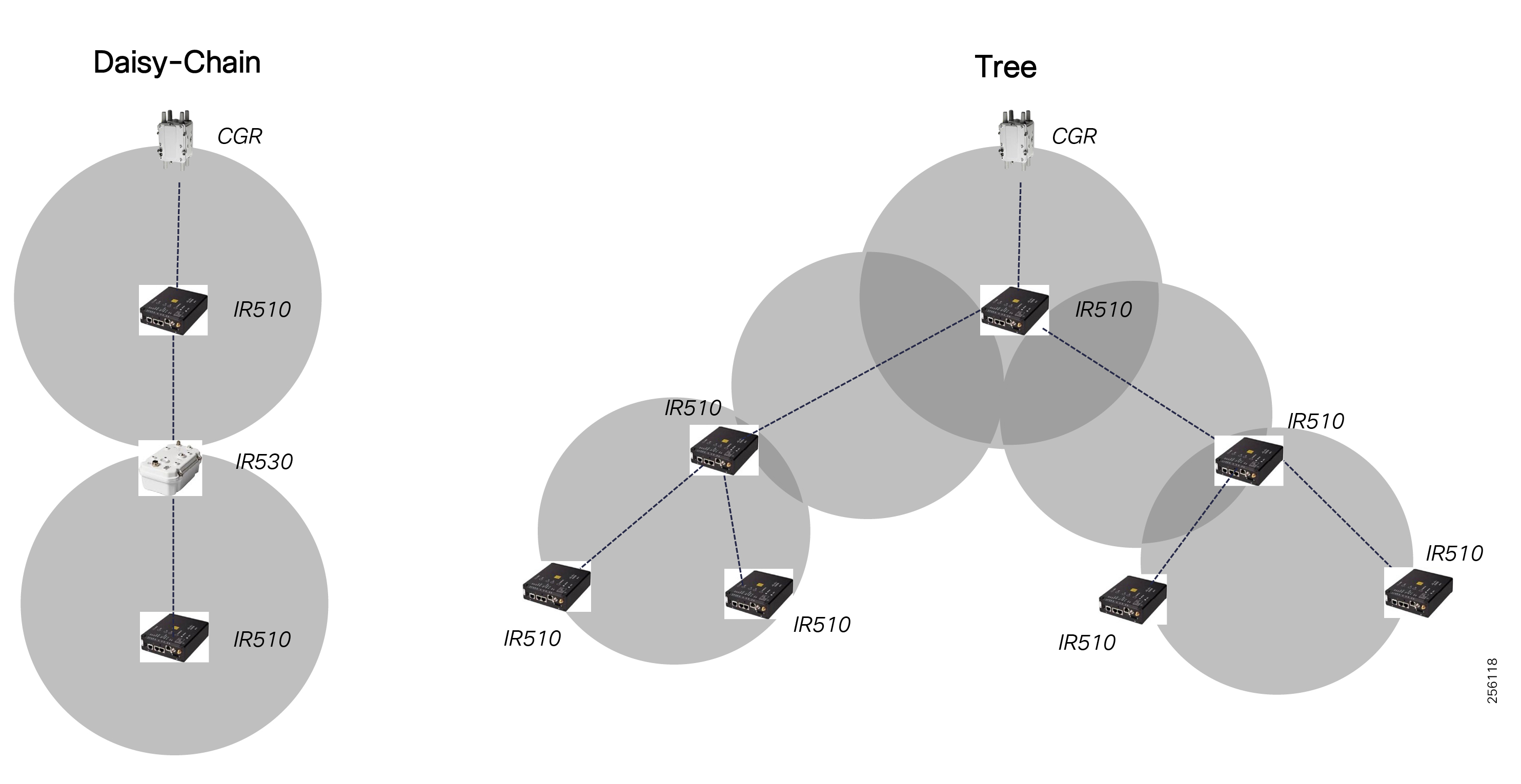
The solution supports dynamic changes to the network topology because of RF changing conditions, referred to as node migration. Intra-PAN migration takes place when a node chooses another node as its parent based on the shortest path cost to the FAR router. Inter-PAN migration occurs when a node decides to join another adjacent PAN ID because of lack of additional parents in its original PAN or better PAN characteristics like lower node density and a better path cost to the new FAR.
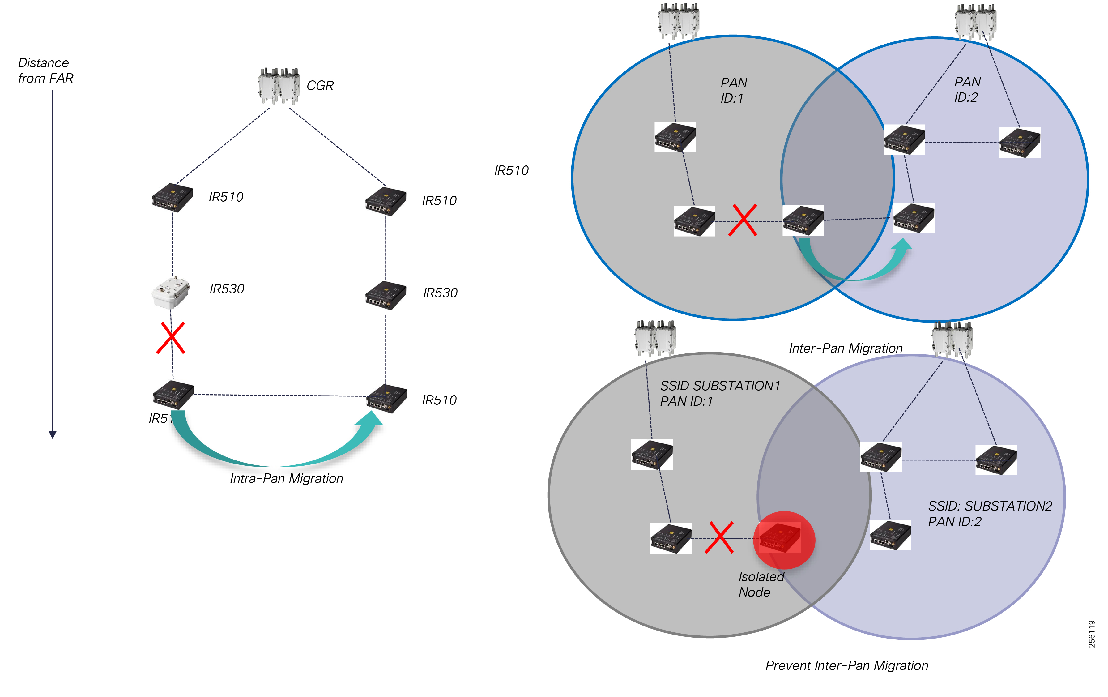
Inter-PAN migration can be prevented by configuring a unique SSID per substation, practically creating two different mesh networks. For these types of designs, administrators should plan for additional redundancy within the PAN where each node has multiple candidate parents to avoid node isolation as shown in Figure 128:
Figure 128 Prevent Inter-PAN Migration
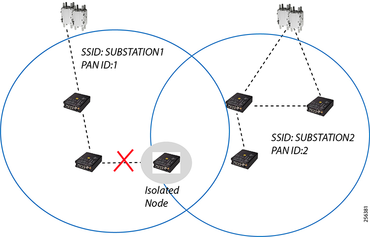
The RF mesh PAN topology will be largely determined by the physical aspect of the grid electrical network and the available utility assets infrastructures (electrical polls, street lighting polls) where communication can be installed. The following factors influence the overall topology:
■![]() Number of FAR devices based on the number of substations and areas with high density of nodes.
Number of FAR devices based on the number of substations and areas with high density of nodes.
■![]() Number of Range Extenders for signal coverage gaps or increased node redundancy
Number of Range Extenders for signal coverage gaps or increased node redundancy
One important aspect of a FAN DA solution is that the RF topology does not have to match the electrical grid feeder network unless specific peer-to-peer communication is required between two DA devices.
Cisco recommends not engineering every node and link on how data is forwarded through the mesh since the solution was designed to be dynamic and to support the end DA device communication based on the best path, shortest path through the mesh independent of the communication equipment feeder asset installation.
Figure 129 Feeder Agnostic Mesh Topology
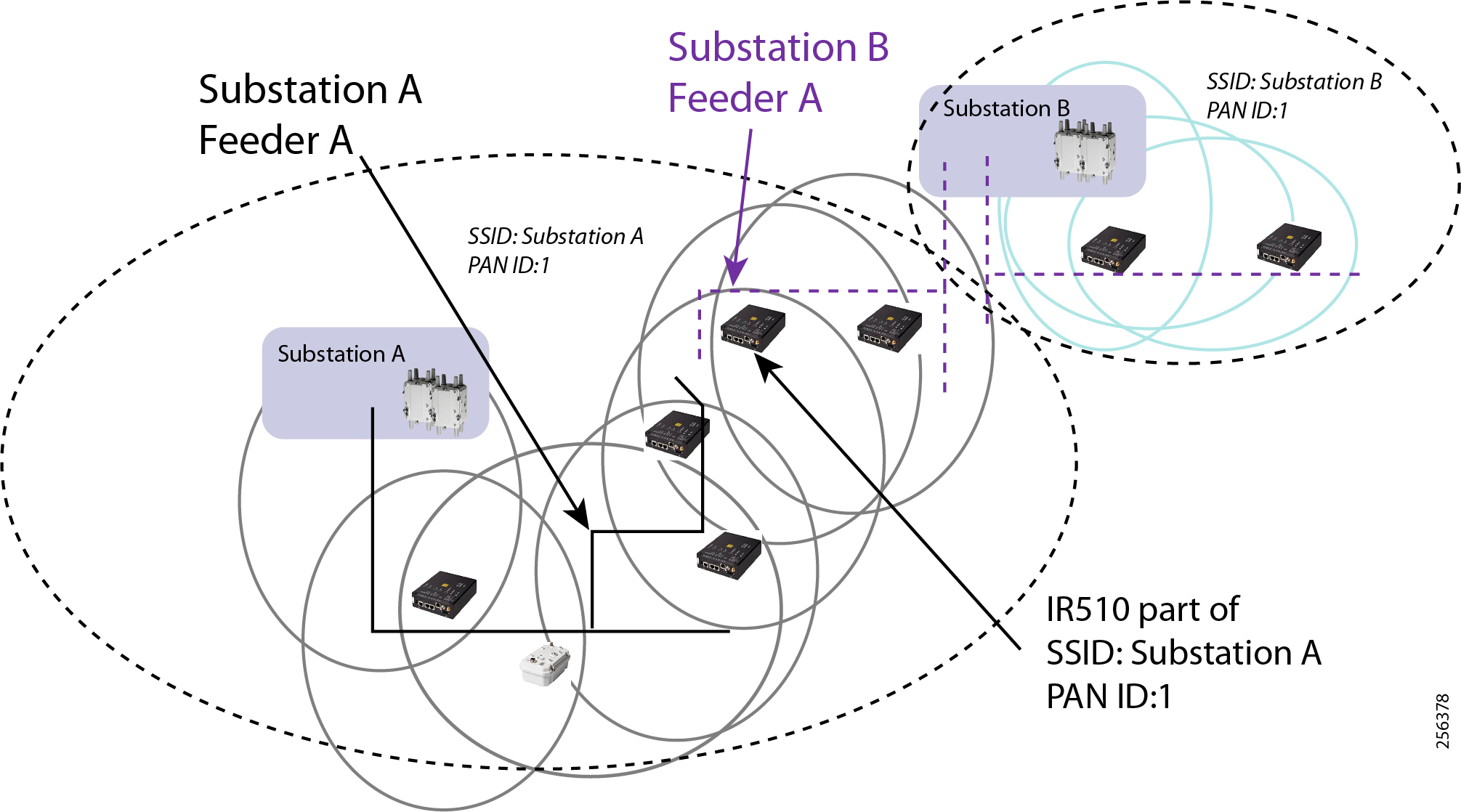
WAN Infrastructure Layer
The Cisco FAN Distribution Automation solution was developed to fit different customer WAN environments.
The solution is agnostic to the customer's WAN transport service (private dark fiber, managed Layer 2 Metro Service, Layer 3 MPLS service, or Private or Managed Cellular service) by using an overlay VPN design based on FlexVPN. The DA packets are encrypted and encapsulated with new IP headers that are hidden from service providers as they travel through the WAN infrastructure and protect the utility grid infrastructure. For Private Cellular services where utility has an acquired licensed spectrum, the FAR devices must be connected to the utility's private modem.
Figure 130 Supported WAN Transport Services
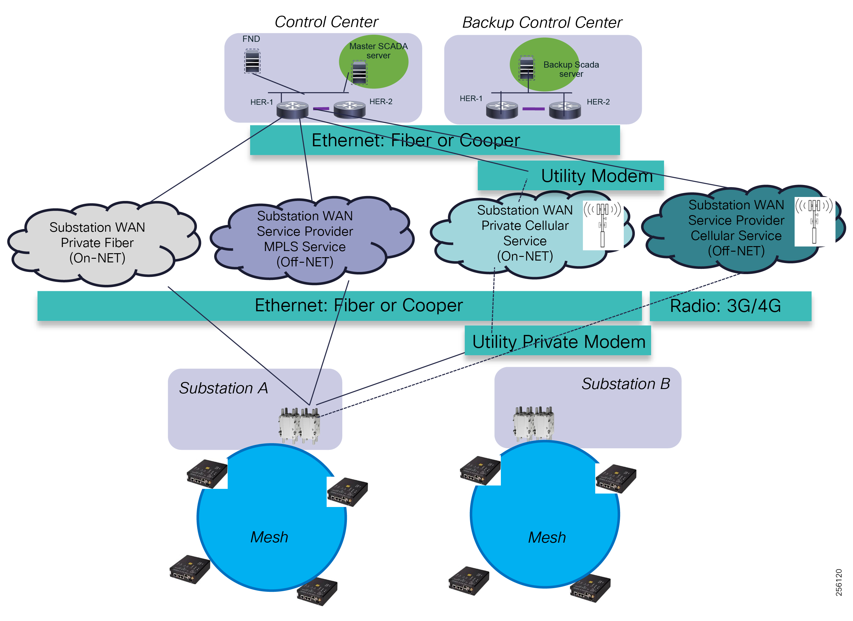
The overlay VPN supports any-to-any or hub-and-spoke topologies at the transport layer. For FLISR scenarios where peer-to-peer is required between substations, customers should consider implementing or acquiring an any-to-any topology to achieve optimal traffic flow between substations.
Customers can provision new services and connect the FAR router directly to the service via an Ethernet or Cellular interface. Security features can be configured to harden the security of the devices. Customers with an existing substation WAN can take the FAN Aggregation layer (FAR devices) and connect them to their existing Substation WAN router or LAN infrastructure. For NERC/CIP substations or for more secure designs, the FAR routers can be connected to the Substation DMZ to ensure that no unauthorized traffic enters the utility network from the FAN network.
Figure 131 Substation Connectivity Options
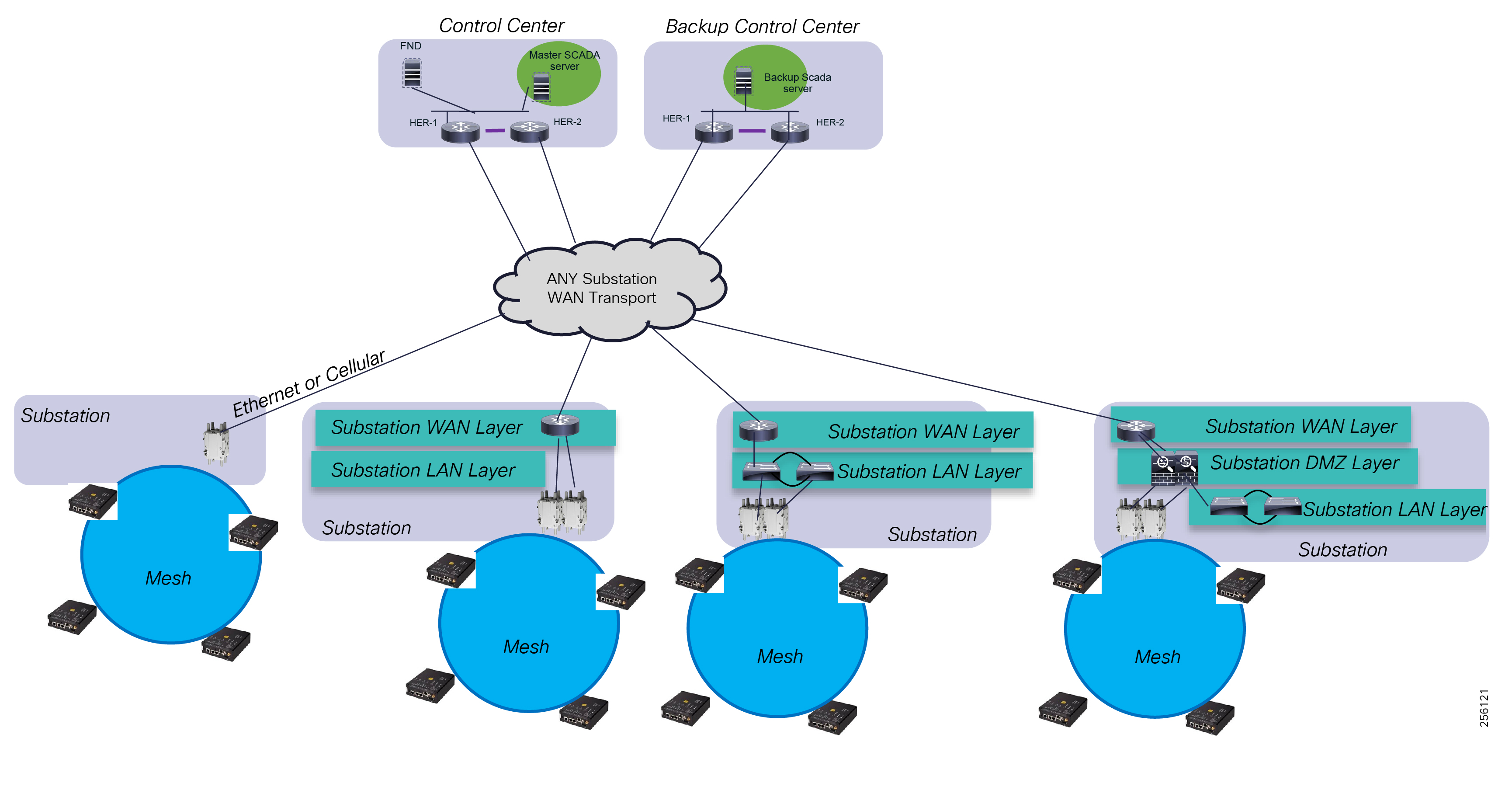
The solution can be customized to fit different SCADA architectures over existing WAN implementations as described in Utility SCADA Systems Architecture Overview. If the WAN infrastructure is not IPv6 or multicast ready, the overlay VPN implementations helps the customer deploy the DA solution without having to make changes to the existing WAN infrastructure.
Cisco has offered different types of security products and VPN technologies such as remote client access and site-to-site VPN for quite some time. The VPN technologies evolved over time into different solutions like EasyVPN and DMVPN. With the release of FlexVPN, Cisco has consolidated the VPN implementation types and their configuration syntax under a single architecture to simplify the solution management.
Cisco FlexVPN incorporates the remote client access functionality of EasyVPN, Cisco VPN Client, and Cisco AnyConnect as well as site-to-site VPN functionality of point-to-point VPN or FlexVPN.
The FAN DA solution does not require any remote client access functionality. The VPN tunnels between the FAR and HER devices are site-to-site VPN tunnel.
The most predominant VPN designs are either FlexVPN or DMVPN. Cisco recommends FlexVPN for the FAN DA solution because its control plane is lightweight out of the box compared to DMVPN. FlexVPN designs are more appropriate for Cellular service deployment or when Cellular is used as a backup solution since usage is metered and utilities typically acquire a shared data plan among all FAN devices. By default, customers can use FlexVPN IKEv2 routing functionality to advertise Control Center routes during the tunnel establishment phase without needing to run a dynamic routing protocol over the VPN tunnel. This approach will conserve additional bandwidth used by the control plane of a routing protocol over the Cellular network.
Another benefit of the FlexVPN over DMVPN is that the VPN Hub servers, the HER devices can implement point-to-point tunnels per remote FAR device, cloned from a virtual-interface template, instead of a DMVPN multi-point GRE interface. This enables customers to configure QoS policies per remote location, especially when remote sites have different transport services. In situations of Private WAN implementations, customers might have a higher WAN interface service for critical or larger substations than for others. In case of Cellular, a remote location could be further located from the Cellular; therefore, its link bandwidth and performance characteristics would be different from other locations. This will avoid the VPN hub from oversubscribing the remote site backhaul link.
FlexVPN and DMVPN support both any-to-any and hub-and-spoke topologies.
Figure 132 FlexVPN Network Topologies
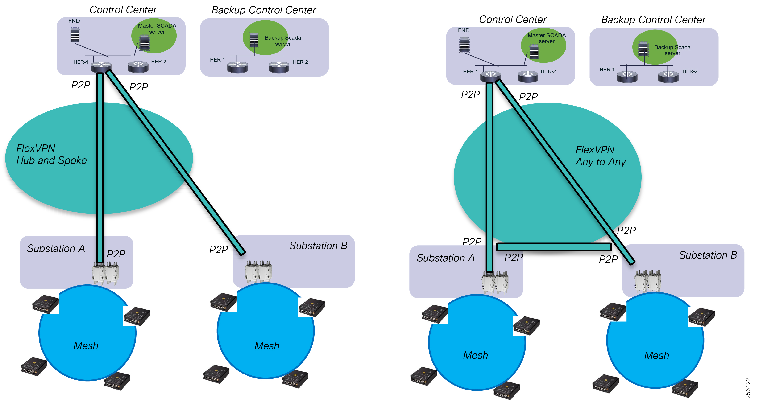
Implementing a hub-and-spoke topology does not mean that Substation A devices or mesh devices can't talk to devices located at Substation B. Additional configuration needs to be applied to either filter the substation routes or only advertise specific Control Center networks. FlexVPN IKEv2 routing simplifies this configuration by associating specific routes per remote location spoke identity.
Customers that have already implemented DMVPN can modify the design to leverage FlexVPN instead; this can be easily done since DMVPN is a subset of FlexVPN.
Headend Infrastructure Layer
The Cisco FAN Headend infrastructure can be added to the existing Control Center LAN infrastructure as a separate block or part of the existing network.
The headend infrastructure requires a few elements like RA, TPS, or HER to be located in the Control Center WAN block in a DMZ area. The FAR devices will need reachability over the WAN transport infrastructure, not the overlay VPN, to the three elements in the DMZ during the FAR device provisioning process.
In addition, the FAN solution requires integration with the existing Active Directory and the certificate (PKI) infrastructure. Customer can also choose to build a dedicated environment.
Figure 133 FAN DA Headend Integration
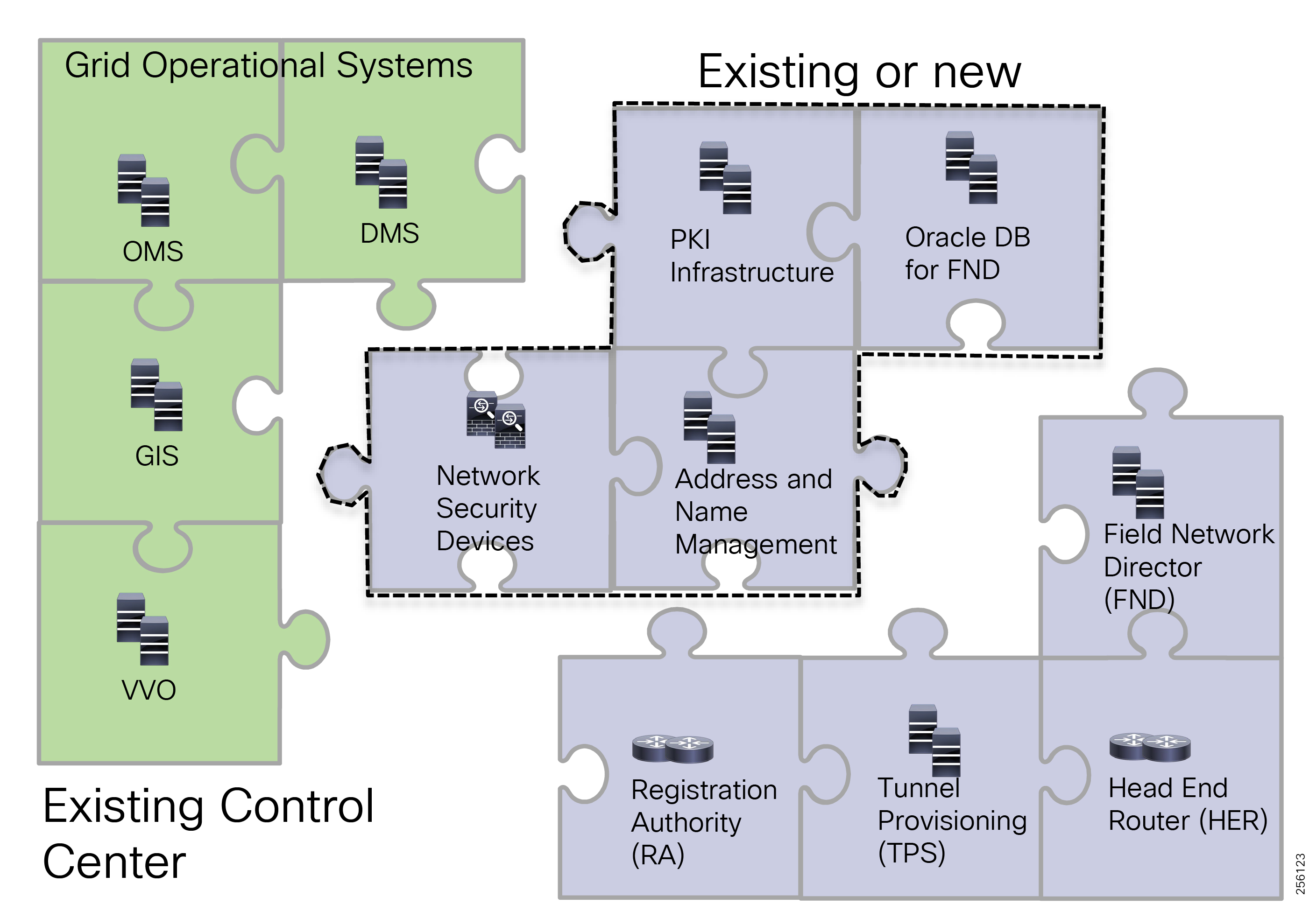
Customers that have deployed the Cisco FAN AMI solution can re-use the AMI Headend infrastructure (HER, RA, TPS, and FND) for the DA solution, as long as the infrastructure is upgraded to the FAN DA software version required.
For small-scale deployments, customers can install multiple components in a virtual environment like VMWare vSphere.
RF Design Considerations
This section starts with an overview of the ISM Band, regulatory requirements, and IEEE 802.15.4 Layer 1 and 2 standards used by the Cisco Resilient Mesh Solution. Readers familiar with these topics can skip the introduction and delve into Cisco Resilient Mesh Release Overview,
It is followed by a detail review of the Cisco Resilient Mesh based on the new IEEE 802.15.4 Option 2 that uses OFDM modulation for increased performance to support the Distribution Automation Use Cases highlighted in Use Cases.
ISM Band Overview
Cisco Resilient Mesh uses the 900Mhz Industrial, Scientific, and Medical (ISM) radio band, which is an unlicensed frequency band for transmission between the FAN communication equipment.
The ISM bands for North America use the following frequency ranges:
1.![]() 902-928 MHz, (26 MHz block)
902-928 MHz, (26 MHz block)
2.![]() 2400-2483.5 MHz, (83.5 MHz block)
2400-2483.5 MHz, (83.5 MHz block)
The following regulatory compliance institutions define the rules for the spectrum usage accordingly to their country policies:
1.![]() USA—Federal Communication Commission (FCC), documented in the Code of Federal Regulations (CFR) Title 47 in Parts 15.247 and Part 15.249
USA—Federal Communication Commission (FCC), documented in the Code of Federal Regulations (CFR) Title 47 in Parts 15.247 and Part 15.249
2.![]() Canada—Industry Canada (IC), documented in RSS-Gen, RSP-100 and RSS-210
Canada—Industry Canada (IC), documented in RSS-Gen, RSP-100 and RSS-210
3.![]() Mexico—NORMA Oficial Mexicana, documented in NOM-121-SCT1-2009
Mexico—NORMA Oficial Mexicana, documented in NOM-121-SCT1-2009
The key takeaways from the FCC documents is that while the ISM band uses unlicensed spectrum, it does not mean that it is not regulated or controlled and that equipment vendors cannot adhere to these rules. Cisco products are certified and compliant with these FCC rules.
The Cisco Resilient Mesh falls under the hybrid systems category therefore the window period of time is based on the number of channels multiply by 0.4, which is 31*0.4 = 12.4 seconds.
The 900Mhz band is optimal for last mile connectivity. The combination of transmit power and wavelength results in a good signal propagation covering distances up to a mile or a mile and a half in environments with line of sight (LoS) and low noise floor, while offering enough bandwidth to support Utility Distribution Applications at a much lower cost than Fiber, Wi-Fi, Cellular, or other radio technologies.
The use of narrow band allows receivers to demodulate the signal at lower RSSI levels. Together with the frequency hopping technique, which spreads the signal over the ISM band, this technology has an operational advantage in environments with higher noise floor levels and interference and allows it to co-exist with other systems operating within the ISM band and supports deployment of dense area of DA Gateways.
Figure 134 FCC 900MHz ISM Narrow Band Spread Spectrum
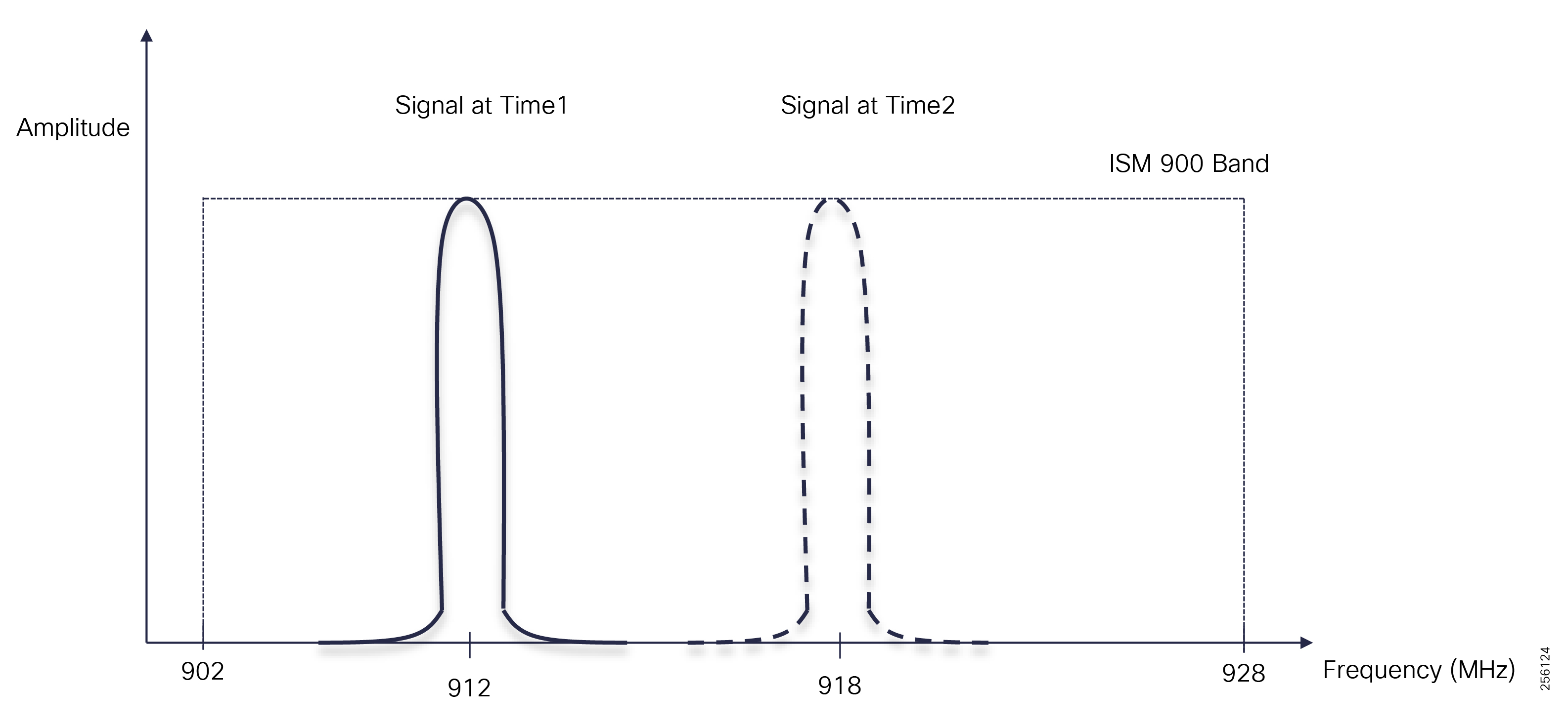
For the CFR Title 47 - Part 15.247 and Part 15.249, please refer to the following URL:
■![]() https://www.ecfr.gov/cgi-bin/text-idx?SID=836adae133a1c7714e83c4db3eec1b2c&mc=true&node=pt47.1.15&rgn=div5 - se47.1.15_1247
https://www.ecfr.gov/cgi-bin/text-idx?SID=836adae133a1c7714e83c4db3eec1b2c&mc=true&node=pt47.1.15&rgn=div5 - se47.1.15_1247
■![]() https://www.ecfr.gov/cgi-bin/text-idx?SID=836adae133a1c7714e83c4db3eec1b2c&mc=true&node=pt47.1.15&rgn=div5#se47.1.15_1249
https://www.ecfr.gov/cgi-bin/text-idx?SID=836adae133a1c7714e83c4db3eec1b2c&mc=true&node=pt47.1.15&rgn=div5#se47.1.15_1249
For the IC RSS-Gen, please refer to the following URL:
■![]() https://www.ic.gc.ca/eic/site/smt-gst.nsf/eng/sf08651.html
https://www.ic.gc.ca/eic/site/smt-gst.nsf/eng/sf08651.html
■![]() https://www.ic.gc.ca/eic/site/smt-gst.nsf/eng/sf01320.html
https://www.ic.gc.ca/eic/site/smt-gst.nsf/eng/sf01320.html
For the NORMA, please refer to the following URL:
■![]() http://dof.gob.mx/nota_detalle.php?codigo=5147409&fecha=21/06/2010
http://dof.gob.mx/nota_detalle.php?codigo=5147409&fecha=21/06/2010
ISM Interference Considerations
Radio networks are prone to interferences and frame retransmission due to the inherent nature of the medium through which the signal must travel.
In general, interference can be classified in the two categories:
■![]() Adjacent Band Interference (Out of band)
Adjacent Band Interference (Out of band)
In the case of adjacent band interference, neighboring communications systems near the ISM band in North America could lead to link poor performance within a specific area, especially when the systems are co-located. Even though FCC has allocated Guard Bands between bands to limit the RF leakage between bands, this will not solve improper customer equipment installation like the one in Figure 135.
Figure 135 Co-Site Interference Example
The most relevant neighboring systems to ISM band are:
■![]() Cellular Band 5, 26 operating on 850Mhz with high transmit power: up to 100 Watts per channel
Cellular Band 5, 26 operating on 850Mhz with high transmit power: up to 100 Watts per channel
■![]() Land Mobile Radios (LMR) systems, which operate in the 851-870 MHz band using up to 35 Watts of transmit power
Land Mobile Radios (LMR) systems, which operate in the 851-870 MHz band using up to 35 Watts of transmit power
Cellular Band 5 is used by Verizon for LTE and for legacy 2G/3G services. Verizon's LTE service primary band in USA is Band 13 (700 MHz). AT&T also uses this band primarily for some 3G (HSPA+) services and for LTE service where the primary bands are not available: Band 12 and 17 operating in 700 MHz range.
Cellular Band 26 is used by Sprint 4G in some rural areas to boost coverage or within buildings.
Figure 136 ISM Adjacent Frequency Bands Considerations
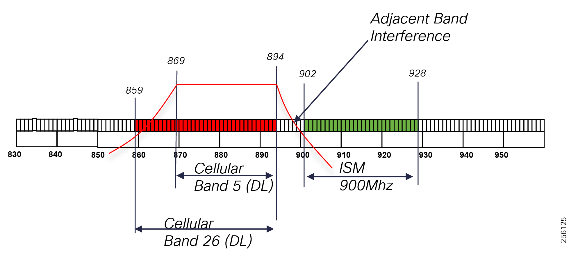
Cisco Resilient Mesh products have built-in filters to reduce the RF leakage from adjacent bands that desensitize the Cisco DA Gateways receiver. Based on the interference system type and location, customers might need to install Cisco DA Gateways away from interference sources. If that's not possible due to limited installation locations, then customers can use external filters that are designed to reduce the interferences on a given frequency range. The filter will be installed between the Cisco DA RF port and the antenna.
It is highly recommended that customers engage a professional RF company to determine what external filters would be required and solve the external interference.
There are two types of In-band interferences. The first one is Co-Channel interference, where two signals (desired and unwanted signal) exist within the same channel at the same time, but with different RSSI levels. This interference can usually be mitigated by relocating the receiving station away from the interferer or closer to the transmitting station to create enough signal level separation so that receiver can demodulate the desired signal.
Figure 137 Co-Channel Interference
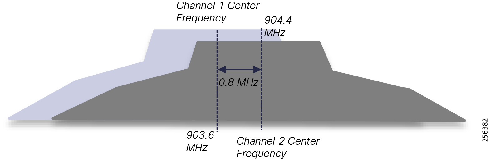
For Cisco Resilient Mesh, OFDM 800 Kbps (Phymode 149) data rate, the delta between the desired signal and unwanted signal should be at least 15dB. The second type of interference is the Adjacent Channel Interference, which occurs when the desired and unwanted signal are in different adjacent channels, but because of the close proximity, the two signals interfere with each other.
Figure 138 Adjacent Channel Interference
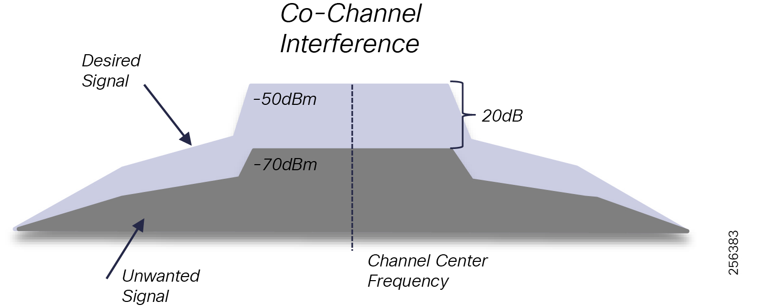
The Co-channel and Adjacent Interferences can be separated into two sub-categories, based on the system ownership. External in-band interference is caused by other systems operating in the same ISM band located in the vicinity of your system for which you don't have authority. Internal or self-interference is caused by other devices within a customer system that are co-located in the same area. Since ISM band is licensed for free, customer should expect in-band interference in the field.
IEEE 802.15.4, because of its robust design that leverages spread spectrum with channel hopping schema, allows multiple systems operating in the ISM band to co-exist as long as equipment manufacturers properly respect the FCC regulations and IEEE 802.15.4 standard and the customer follows common RF best practices for:
■![]() Physical separation between transmitters
Physical separation between transmitters
■![]() System traffic load design in terms of node density within and area and transmitter duty-cycle utilization
System traffic load design in terms of node density within and area and transmitter duty-cycle utilization
Carrier Sense Multiple Access with Collision Detection (CSMA/CD) assists with frame corruption prevention due to in-band interference, but when collision does occur, IEEE 802.15.4 's MAC layer reliability services will ensure that lost frames are retransmitted so that the utility applications are not affected.
The more challenging scenario is when external systems are proprietary and do not adhere to industry standards to implement CSMA/CD or purely use a high duty-cycle transmission plan within the FCC limits. Some Fault Indicators systems are an example of such implementation.
Customer should take a more holistic approach to deploying Smart Grid technologies by evaluating vendors and their products for interoperability and co-existence.
Take into consideration the following external systems that operate within ISM band during the RF planning phase:
■![]() Advanced Metering Infrastructure (AMI)
Advanced Metering Infrastructure (AMI)
■![]() Fault Location Indicators Sensors
Fault Location Indicators Sensors
Self-interference can be mitigated by a proper RF design since the customers own the infrastructure and have full control over the system, installation location, antenna types, etc.
It is essential that customers work with a professional RF company, perform proper site survey of the area, and model the RF signal propagation using advanced software design for this type of tasks.
PHY and MAC Layers (IEEE 802.15.4g/e) Standard Overview
In 2011, the IEEE developed the 802.15.4 technical standard as a framework for low cost, low rate, and low power Wireless Personal Area Network (WPAN) for the Physical Layer (Layer 1) and the MAC or Data Link Layer (Layer 2). It is based on the unlicensed spectrum ISM bands.
The main goals used to develop the standard were:
1.![]() Thousands of devices in a small area
Thousands of devices in a small area
4.![]() Multi-Hop for communication beyond the device range
Multi-Hop for communication beyond the device range
5.![]() Self-Organization with dynamic routing
Self-Organization with dynamic routing
6.![]() Coexist with other systems operating in the same unlicensed frequency
Coexist with other systems operating in the same unlicensed frequency
In 2012, IEEE 802.15.4g amendment was developed to include additional outdoor physical layer data rates and modulation for Smart Utility Networks (SUN) and the modification of the MAC layer to support the new formats:
1.![]() Multi-Rate and Multi-Regional (MR) Frequency Shifting Key (FSK)
Multi-Rate and Multi-Regional (MR) Frequency Shifting Key (FSK)
2.![]() MR Orthogonal Frequency-Division Multiplexing (OFDM)
MR Orthogonal Frequency-Division Multiplexing (OFDM)
3.![]() MR Offset Quadrature Phase Shift Keying (QPSK)
MR Offset Quadrature Phase Shift Keying (QPSK)
Part of the standard IEEE has defined multiple options for OFDM modulation. Cisco has implemented OFDM Option 2 profile as part of the Resilient Mesh release to increase the physical link data rates.
Note: Currently, only the 1200, 800, 400, and 200 data rates are supported. The remaining data rates will be supported in the future through software updates.
The standards define a general frame format for all packet transmissions. The frame format consists of both the physical and the MAC layer. The frame format consists of three parts:
Figure 139 IEEE 802.15.4 General Frame Format
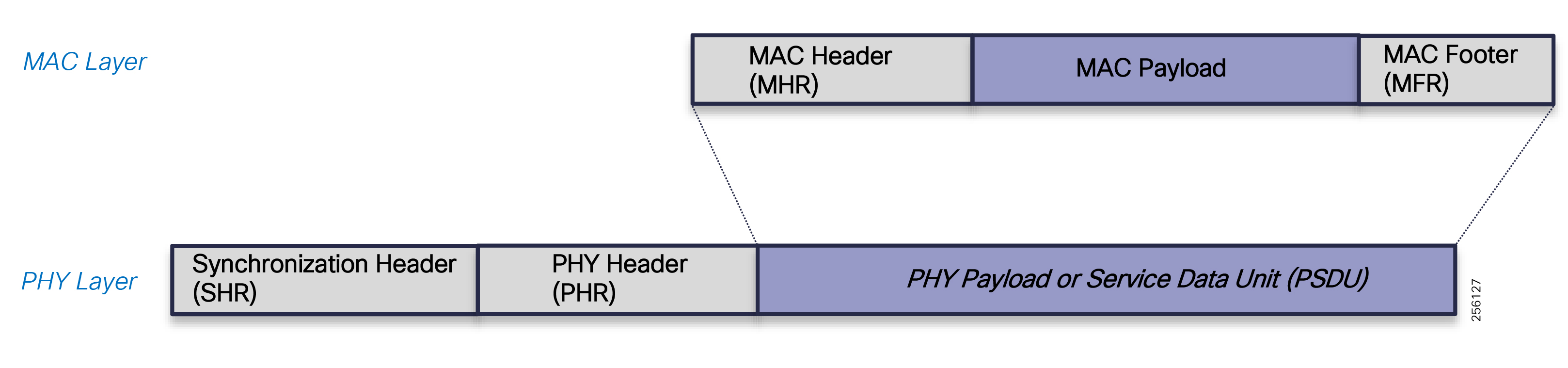
The PHY layer uses a Synchronization Header and Physical Header. The Synchronization Header has a Preamble field that is used to RF symbol synchronization between the sender and receiver so that the receiver can correctly receive the following frame. The Start of Frame Delimiter (SFD) indicates to the receiver the end of the Preamble field and the beginning of the frame payload or the Payload Service Data Unit (PSDU).
Initially, the maximum PSDU size was 127 Bytes but it was increased later on to 2047 Bytes.
Figure 140 PHY Layer Frame Fields
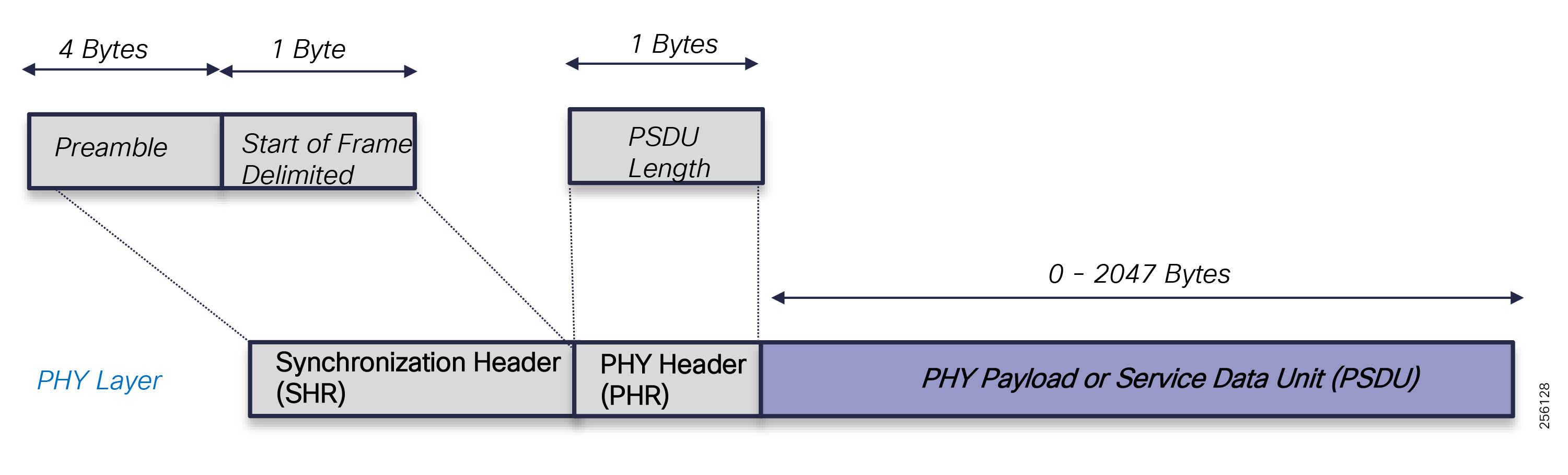
Note: The SHR and PHR are specific to each PHY mode of operations and can be found in Clause 6 of the standard. Please refer to the following URL:
■![]() https://standards.ieee.org/standard/802_15_4-2006.html
https://standards.ieee.org/standard/802_15_4-2006.html
For the IEEE 802.15.4g Standard, please refer to the following URL:
■![]() https://standards.ieee.org/standard/802_15_4-2011.html
https://standards.ieee.org/standard/802_15_4-2011.html
At the MAC layer, the IEEE 802.15.4e standard defines the following fields within the frame (MPDU): the MAC Header (MHR), MAC Payload, and MAC Footer.
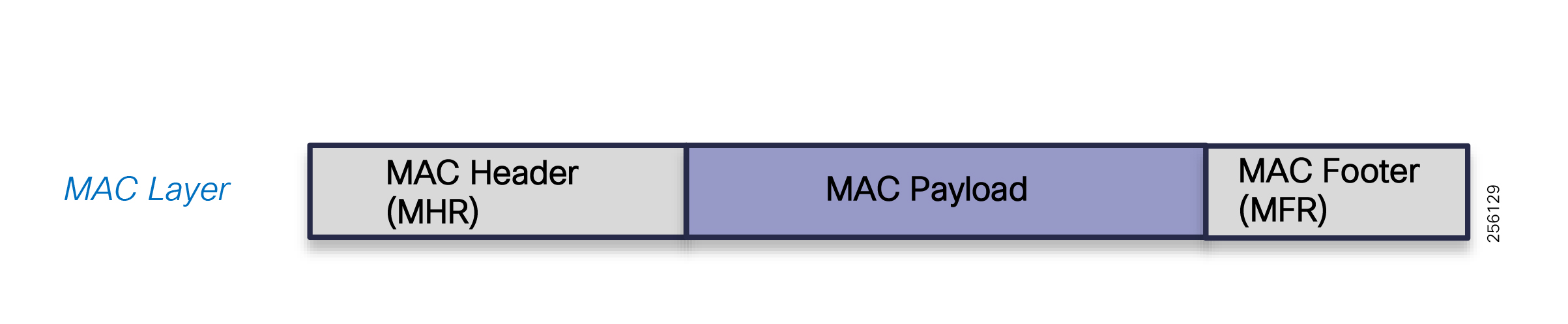
The four types of MAC frames are:
Note: The MAC Payload is not used for ACK frames.
The MHR and the MFR is common to all MAC frames. The MHR has several subfields that are described in the standard, but the ones of interest are the Frame Control subfields, which contains flags that tell the receiver how to interpret the rest of the header fields and whatever the frame needs to be acknowledged.
The Security Field indicates if the MAC frame contains the optional Security Header Field and if the MAC payload is protected.
PAN ID Compression is uses to indicate if both Source and Destination PAN ID fields must be present in the Address Field.
The Destination and Source Mode fields specify if the PAN ID is present within the Address Field and if the Address size: Destination or Source is in native 64-bit format or the compressed 16-bit format.
The Sequence Number field is used to track the acknowledgments for the data packets and the Address Field and Auxiliary Security Head, which is present only when Security Enable field is set to 1.
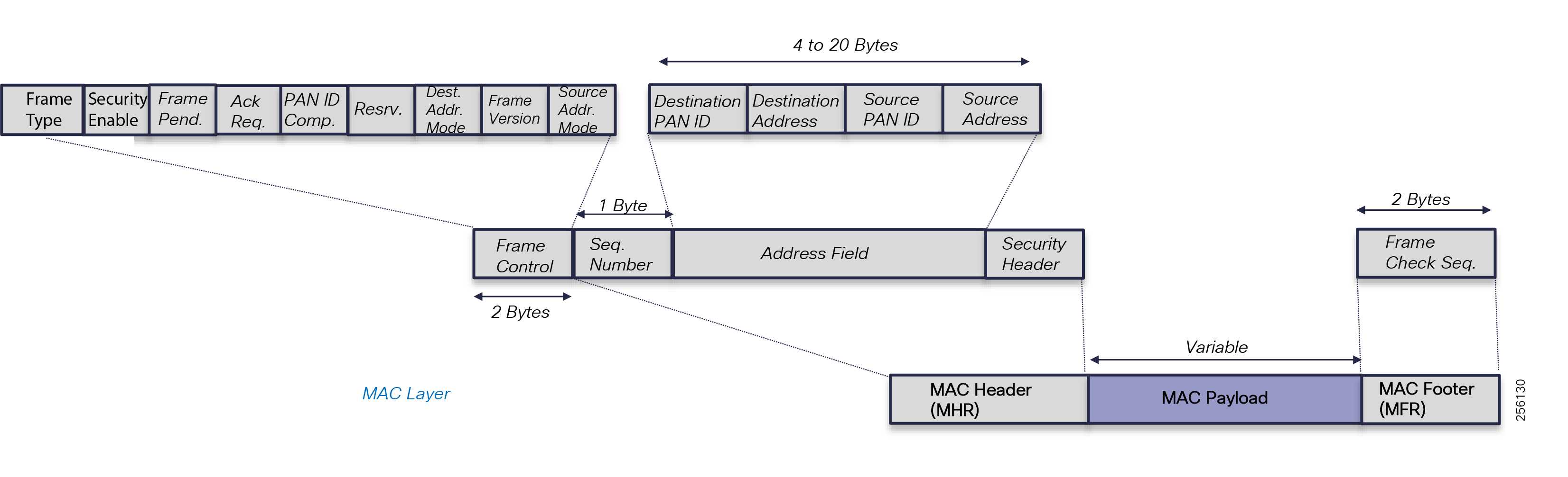
The Address Field varies in size, based on the flags set in the Frame Control subfields.
At the end of the MAC frame, there is a MAC Footer that is a Frame Check Sequence field that is calculated over the MHR and MAC Payload for frame data corruption.
MAC Payload follows the MHR and its payload structure and size varies based on the MAC frame type. It is briefly described below. If security is enabled, then the payload is protected through encryption.
Enhanced Beacons (EB) messages are used by the Cisco DA devices to disseminate useful information regarding the PAN to which they belong so that other devices that are looking to joining a PAN can discover the available networks in the vicinity. Joining nodes are nodes that have not yet been granted access to the PAN. As such, joining nodes cannot communicate IPv6 datagrams with neighboring devices. The EB message is the only message sent in the clear that can provide useful information to joining nodes to select the best PAN and best neighbor within a PAN. The following information is sent in the EB frame:
■![]() SASID, which is used as a filter so new devices can avoid joining foreign networks.
SASID, which is used as a filter so new devices can avoid joining foreign networks.
■![]() GTK info: Include GTK ID and a SHA256 key hash. Mesh nodes use it during the join process to check if it has the GTK or not. This IE is also used when the GTK is renewed by the FAR. Each node can store up to four keys per PAN and keys for up to two different PANs.
GTK info: Include GTK ID and a SHA256 key hash. Mesh nodes use it during the join process to check if it has the GTK or not. This IE is also used when the GTK is renewed by the FAR. Each node can store up to four keys per PAN and keys for up to two different PANs.
■![]() PAN size: number of RPL nodes. Value only updated by the FAR/RPL root.
PAN size: number of RPL nodes. Value only updated by the FAR/RPL root.
■![]() Path cost to the root: RPL Rank.
Path cost to the root: RPL Rank.
■![]() Unicast/listening Schedule: Used to implement the channel-hopping algorithm.
Unicast/listening Schedule: Used to implement the channel-hopping algorithm.
Joining devices also use the RSSI value of the received EB message to determine if a neighbor is likely to provide a good link. The transceiver hardware provides the RSSI value of each frame. Neighbors that have an RSSI value below the minimum threshold during the course of receiving EB messages are not considered for PAN access requests.
Figure 143 MAC Beacon Frame Fields
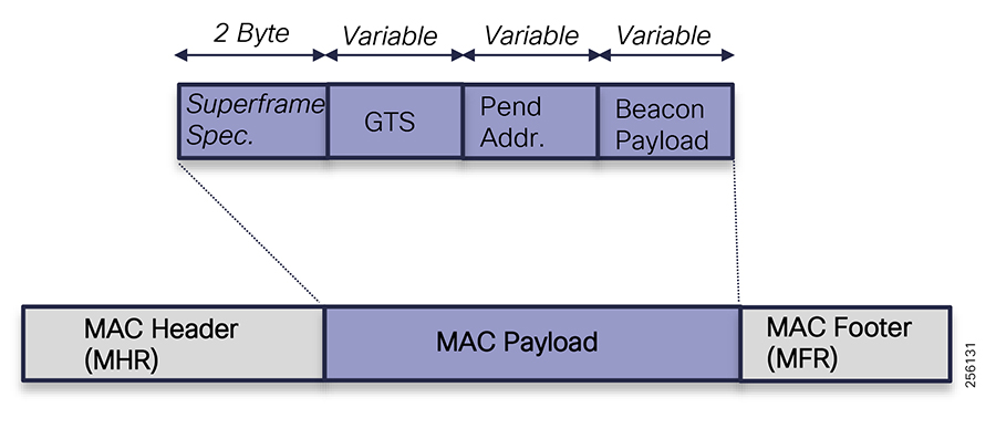
Nodes use MAC command frames to:
■![]() Association request and response
Association request and response
■![]() Disassociate with a particular network
Disassociate with a particular network
■![]() Request Beacon frames, GTS info
Request Beacon frames, GTS info
■![]() Send notification for PAN ID conflict or Orphan scenarios
Send notification for PAN ID conflict or Orphan scenarios
The Command Type field specifies the command type that is found in the Command Payload field. The command types include Association Request and Association Response, which can be found in the Standard Reference Documentation.
Figure 144 MAC Command Frame Fields
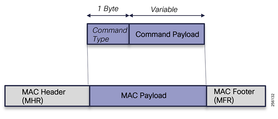
Data frames can be sent as unicast or broadcast with a retransmission mechanism. If an ACK is not received, the node will try to re-transmit it up to eight times at the MAC layer. If the packet is sent upstream, the node will also try to send it to a backup parent (retransmission at the network layer) up to 8 times.
Since version 6.0-19, the number of retransmissions will be based on the QoS classification of the packet, where packets with higher Assured Forwarding (AF) class and low drop probability markings will be retransmitted more than lower AF classes.
Both type of packets will always carry an IE describing the Unicast listening schedule of the sender.
Figure 145 MAC Data Frame Fields
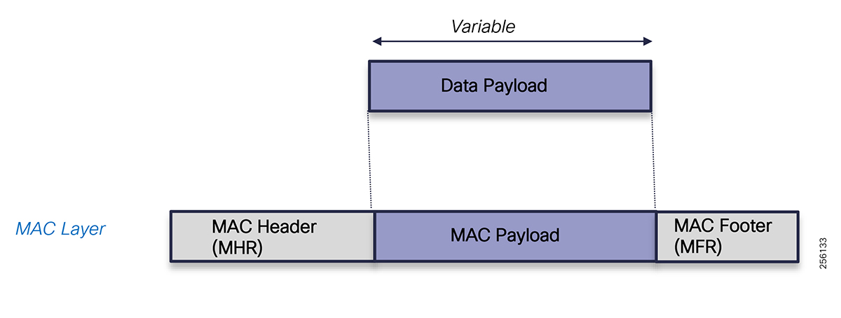
In the current implementation, any data packet must be acknowledged. Receiving an ACK packet will help to compute the ETX value for the link (used by RPL) as well as the forward RSSI for the sending node. The ACK packet is encrypted like any other Data frame.
Figure 146 MAC ACK Frame Fields
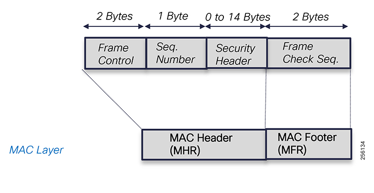
For the IEEE 802.15.4e Standard, please refer to the following URL:
■![]() https://standards.ieee.org/standard/802_15_4-2011.html
https://standards.ieee.org/standard/802_15_4-2011.html
Around the same time in 2012, Wireless Smart Utility Networks (Wi-SUN) Alliance was formed to drive industry adaption of the IEEE 802.15.4g, develop industry market requirements (MRD) and Technical Profile Specifications (TPS), and establish a certification program for multi-vendor equipment interoperability testing.
Cisco has been a member of the Wi-SUN Alliance from the beginning and is a big promoter for open standards and multi-vendor interoperability.
At the time of the writing, Cisco was going through the certification process for the Wi-SUN 1.0 certification.
Cisco Resilient Mesh Release Overview
Cisco Resilient Mesh is the second-generation outdoor wireless solution based on ISM band (900 MHz) targeted for the Americas region. It is based on the newly launched DA Gateway product, the IR510, the range extended IR530, and the CGR WPAN OFDM module. It leverages a new software release (CG-Mesh 6.0.19) that includes enhanced features like Adaptive Modulation and Adaptive Data Rate and new capabilities like Edge Compute to support Utility Customers' Distribution Automation use cases.
General RF Design Considerations
Each outdoor wireless mesh deployment is unique since each environment has its own local radio characteristics based on the equipment installation locations, obstructions, noise floor, and external interferences.
Typically, the following factors have a major influence over the RF design:
■![]() Geographical location, terrain type: mountains, hills or plains
Geographical location, terrain type: mountains, hills or plains
■![]() Demographics: urban, sub-urban or rural areas
Demographics: urban, sub-urban or rural areas
■![]() Climate: tropical, polar, dry, temperate, etc
Climate: tropical, polar, dry, temperate, etc
■![]() Utility profile: service territory and number of grid assets
Utility profile: service territory and number of grid assets
Figure 147 Geographical Locations and Demographics
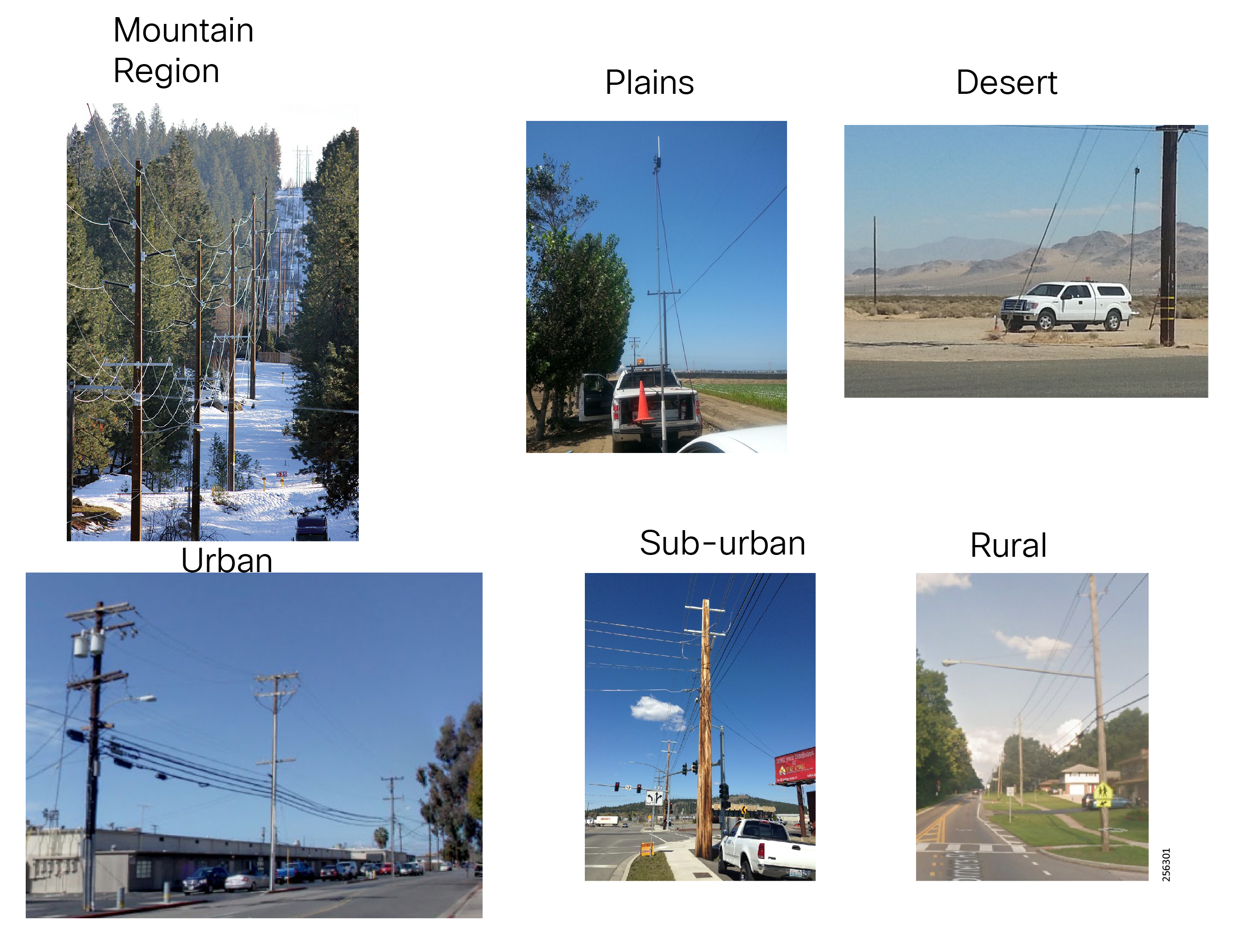
Mountain or hilly areas typically affect the device's LoS and free space required between nodes to have a good reliable link with low packet error rate (PER). Two adjacent devices could have different elevation points, which will influence how antennas are installed. Tree branches and leaves could obstruct some of the path between the nodes, which leads to variation on the RSSI level between the nodes that require good fading margins for the links to be stable. Flat areas have more open spaces and allow for better signal propagation, resulting in greater link distance. In desert areas, foliage typically is not a problem, but differences in temperature between day and night will result in couple or few dBm changes in the RSSI values.
The demographics introduce different RF challenges. In urban areas, a lot more noise and interferences exists because of the multitude of other RF systems or commercial business that have elements that produce noise. An RF design for an urban area will look different then a design for a rural area because the node density per area would be different. In urban areas, utility assets are closer (between a half mile and one mile) whereas in rural areas assets could be more than two miles apart from each other, therefore requiring additional range extenders to extend the signal coverage. The urban area is more prone to interference due to the clutter diversity (such as airports and hospitals) that exists within the metropolitan area.
Figure 148 Urban Clutter Diversity
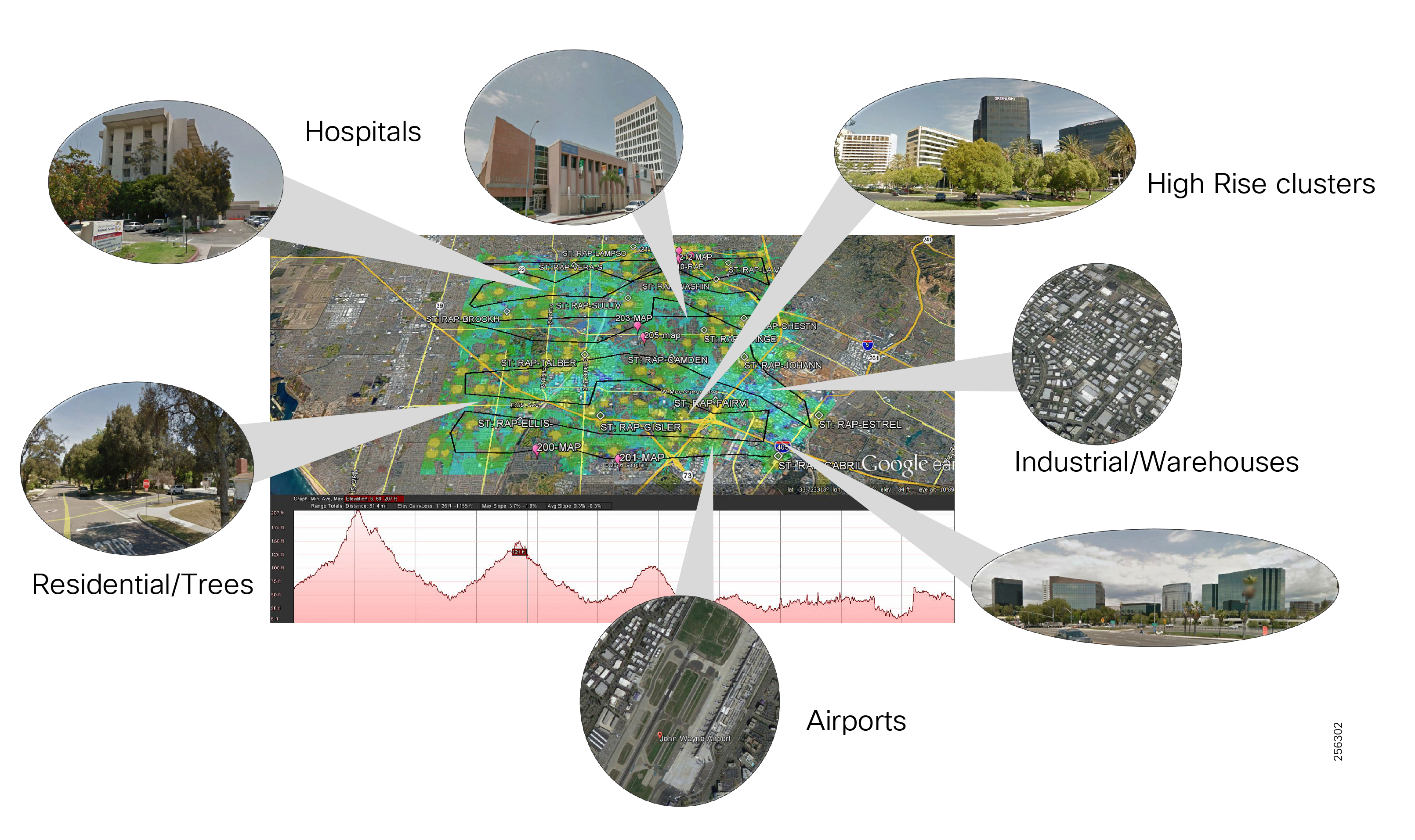
The utility service territory and the number of grid assets that need to be connected affect the number of mesh devices the solution requires. A large utility most likely will have a presence in different demographic regions. In urban areas, the Distribution Automation feeder length is only a couple of miles long since the substation density per area is greater than rural areas. This allows the design to have multiple take out points. The PAN coverage will be small with higher density nodes and allow for higher capacity. The design will only use range extenders in areas that coverage is not that great due to obstacles or RF interference. In sub-urban areas, the substations will be more spread out, with longer feeder length, up to 4 to 5 miles. This design will require additional range extender to increase the coverage area and to increase the redundancy of the PAN by designing additional paths between the nodes.
Rural deployments will cover long feeders up to 10 miles, which will leverage a larger number of range extenders than in urban areas. This type of design will lack the redundancy since it has a daisy-chain topology. Customers should plan to design additional redundant path using just range extenders.
Medium and small utilities will typically have only one or two RF designs covering urban and/or rural with a lower number of substations and grid assets to connect. For designs with a small number of substations and FAR routers in order to keep the mesh depth to a reasonable number of 4 to 5 hops, customers can use range extenders to aggregate nodes, therefore reducing the number of hops between nodes, or install additional FAR routers that use cellular for backhaul connectivity.
Communication Equipment Placement
In this design guide, the FARs or CGRs are assumed to be installed within the utility substation premise and to leverage the substation WAN for backhaul transport. This will keep the network operation costs down by reusing the existing WAN infrastructure. The solution does not require any changes to the substation WAN since it's using an overlay VPN design that makes the Cisco Resilient Mesh design agnostic to the WAN design.
Utilities typically already have a radio communication infrastructure within the substations: RF towers or wooden polls where the CGR routers can be installed. The CGR will be connected using fiber back to the substation communication hut where it will be connected to the substation LAN or WAN router.
Figure 149 Substation Communication Tower
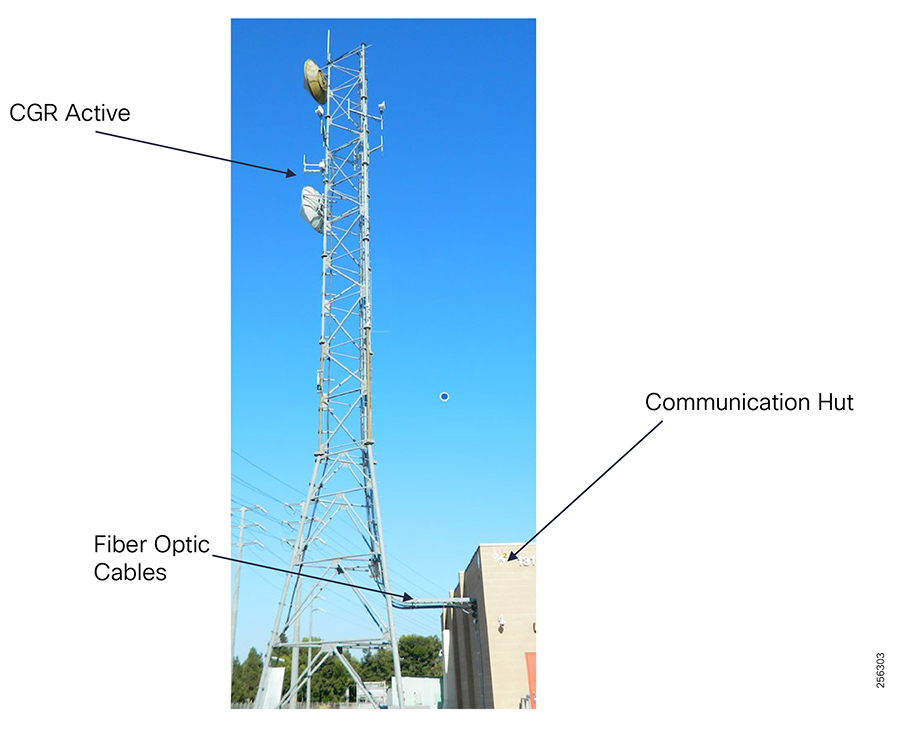
For urban substations that are surrounded by tall residential or commercial buildings that obstruct the CGR signal propagation, customers will have to install more than one CGR router outside the substation yard. For that, customers can extend the fiber connectivity from the substations onto the feeder and install the CGR on the feeder itself. If the fiber extension is not an option, then customers can leverage Wi-Fi point-to-point or mesh to extend the substation connectivity.
The DA Gateways and the IR510 typically is installed on the feeder overhead infrastructure inside the grid device controller enclosure that is mounted on the poll.
Figure 150 IR510 Overhead Line Installation
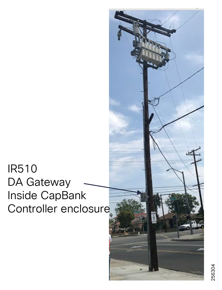
However, some instances exist in the urban or residential area where the utility uses an underground distribution infrastructure. In that case, the communication equipment is installed on pad mounts or within manholes.
Figure 151 IR510 Underground Line Installation
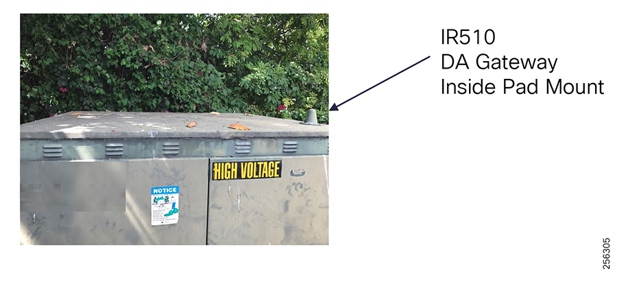
These locations are fixed and are part of the Feeder Automation planning. Together with the substation locations, it will be used as the initial data source for the RF design development. Customers will need to provide each location GIS coordinates and the type of grid asset that will be connected. RF engineers will use professional tools to model the first RF design and determine if additional coverage is required. If range extenders and IR530 are required, then customers also need to provide the potential infrastructure asset list (poll IDs and locations where the additional communication equipment can be installed). The RF engineering team will rework the RF design model to take into consideration these additional locations.
Figure 152 IR530 Street Lighting Poll Installation
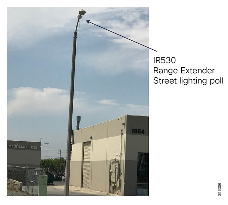
Equipment Antenna Considerations
Cisco provides customers with a variety of antenna options that were specifically designed for this solution. Because the radio network is a mesh network, a node must communicate with more than two nodes, typically in opposite directions. This requirement leads to installations that use omni-directional antennas, unless a node is a leaf-node. In that case, customers can use a directional antenna.
The following antennas are available for use:

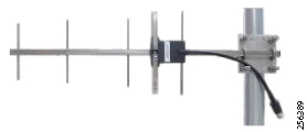
For the Cisco Omni Low Gain (ANT-WPAN-OD-OUT-N) Datasheet, please refer to the following URL:
■![]() http://www.cisco.com/c/en/us/td/docs/routers/connectedgrid/antennas/installing/cg_antenna_install_guide/ANT-WPAN-OD-OUT-N.html
http://www.cisco.com/c/en/us/td/docs/routers/connectedgrid/antennas/installing/cg_antenna_install_guide/ANT-WPAN-OD-OUT-N.html
For the Cisco CGR 1240 Omni 2.3 dBi Gain (ANT-MP2-I-OUT-M) Datasheet, please refer to the following URL:
■![]() http://www.cisco.com/c/en/us/td/docs/routers/connectedgrid/antennas/installing/cg_antenna_install_guide/ANT-MP2-I-OUT-M-ANT-MP2-I-O-SS-M.html
http://www.cisco.com/c/en/us/td/docs/routers/connectedgrid/antennas/installing/cg_antenna_install_guide/ANT-MP2-I-OUT-M-ANT-MP2-I-O-SS-M.html
For the Cisco Omni 54 dBi Gain (ANT-LPWA-DB-O-N-5) Datasheet, please refer to the following URL:
■![]() https://www.cisco.com/c/en/us/td/docs/routers/connectedgrid/antennas/installing-combined/industrial-routers-and-industrial-wireless-antenna-guide/ANT-LPWA-DB-O-N-5.pdf
https://www.cisco.com/c/en/us/td/docs/routers/connectedgrid/antennas/installing-combined/industrial-routers-and-industrial-wireless-antenna-guide/ANT-LPWA-DB-O-N-5.pdf
For the Cisco Yagi 9 dBi Gain (ANT-WPAN-Y-OUT-N) Datasheet, please refer to the following URL:
■![]() http://www.cisco.com/c/en/us/td/docs/routers/connectedgrid/antennas/installing/cg_antenna_install_guide/ANT-WPAN-Y-OUT-N.html
http://www.cisco.com/c/en/us/td/docs/routers/connectedgrid/antennas/installing/cg_antenna_install_guide/ANT-WPAN-Y-OUT-N.html
RF Design Development Process
Developing a good RF design can be a complex process for engineering teams that lack the RF expertise and can lead to failed implementations. For that reason, it is critical that customers acquire the proper resources to assist with the RF design development. There is no good substitute for RF field experience and practice.
In order to successfully develop an RF design and deploy the Cisco Resilient Mesh solution, customers should engage a Cisco partner or Cisco Services to assist with the RF design phase for their environment.
The RF design phase should encompass the following process steps:
1.![]() Develop Utility application model
Develop Utility application model
2.![]() Initial Field site survey samples
Initial Field site survey samples
3.![]() Develop predictive RF Model using software tools
Develop predictive RF Model using software tools
4.![]() Validate RF Model in the Field
Validate RF Model in the Field
Figure 153 RF Design Development Process
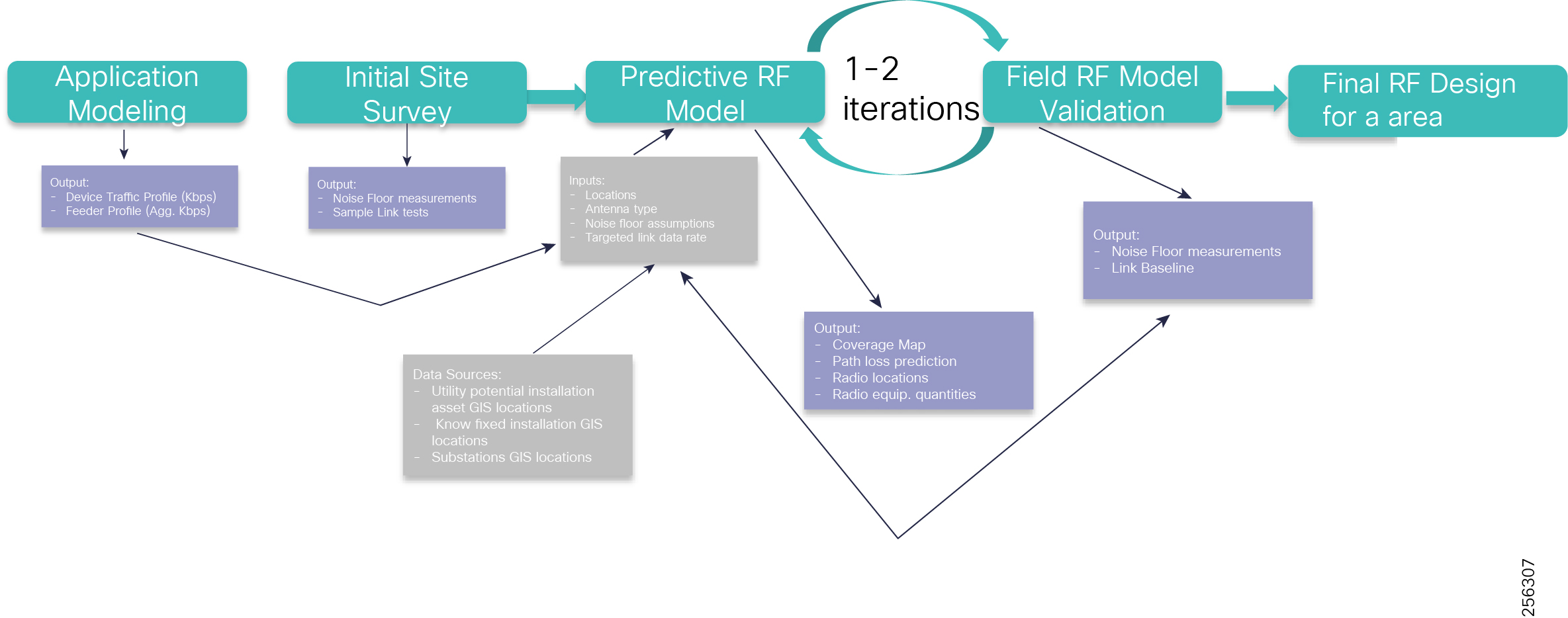
In the Application Model step, customers should determine the application communication requirements based on the different use cases that the network must support. A device communication traffic profile should be developed for each grid device type (such as capacitor bank controller and recloser), identifying the bandwidth and latency required during steady state and normal grid operations, and the burst rate for the worst case scenario when there are a lot of events happening in the electrical grid.
With this information, a feeder traffic profile can be developed based on the feeder's device types and quantities, which will be used with the RF modeling output to determine the network mesh depth, number of take out points, or CGR routers to ensure that the network would support the DA applications traffic profiles.
The purpose of the Initial Field survey is to collect samples of the RF characteristics (noise floor readings, in-band, and external interference from a few locations) that would be used as input in the predictive RF Modeling tool so that the output model will be more accurate. In addition, it will allow for the discovery of unknowns since the RF modeling tools don't use real-time data and eliminate any surprises later in the deployment.
Using advanced RF modeling tools, based on the following set of input data, a signal coverage map will be generated that depicts potential RF links between devices that meets the desired signal RSSI criteria:
■![]() GIS coordinates of the utility assets where the communication equipment can be installed
GIS coordinates of the utility assets where the communication equipment can be installed
■![]() Equipment installation height and antenna type
Equipment installation height and antenna type
■![]() Initial Field site survey data
Initial Field site survey data
■![]() Desired Link Modulation and Data Rate
Desired Link Modulation and Data Rate
Figure 154 RF Heat-map with Potential Links
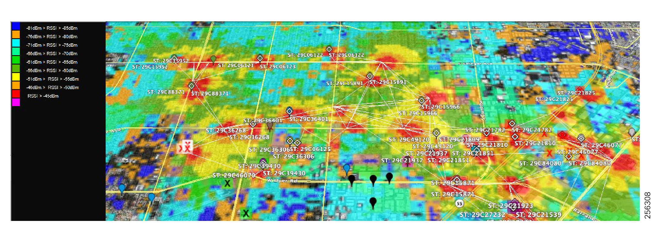
An RF engineer would be able to identify the following:
■![]() Signal coverage gaps; isolated nodes
Signal coverage gaps; isolated nodes
■![]() Single points of failure; nodes with a single parent
Single points of failure; nodes with a single parent
■![]() Oversubscribed nodes; parents with large number of children
Oversubscribed nodes; parents with large number of children
■![]() Long paths; nodes exceeding normal hop count
Long paths; nodes exceeding normal hop count
The engineer could then refine the RF Model by adding additional range extenders or CGR routers to increase the number of take out points.
Based on the RF Model output, a second Field Site Survey is required to validate the predicted RF links and gather additional RF samples from other locations. The RF team should baseline the candidate links identified by the RF Model in terms of throughput, delay, and packet loss. The link test should be done as close as possible to the equipment final installation point.
Using the results collected during this phase, the RF team can determine if the RF Model is good enough or if further refinements are required. Typically, it takes one to two iterations before finalizing the RF Model.
Once the equipment is deployed in the field, the customer can use the Cisco Resilient FND management tools to monitor the link health over time between the DA gateways. The FND allows customers to define the link ETX range to categorize links as Good, Poor, and Fair.
Network RF Segmentation
The Cisco Resilient Mesh uses the concept of SSID and PAN ID. The SSID is a unique global name that represents the Utility network. Within the utility network SSID, each coordinator or CGR router forms a PAN network that runs its own RPL instance. Mesh nodes must be configured with the SSID information and, based on the available PANs, nodes will join a specific PAN. In the case where the CGR routers are installed within the substation premise, each substation and its neighborhood area will have one PAN ID. This logical configuration will allow nodes to perform Inter-PAN migration as long as nodes can hear nodes in adjacent PANs and can establish a stable link. In addition, nodes can be move from one substation area to another if customers would like to redeploy a node.
Note: Nodes will cache information for a maximum of two PANs. When redeploying a node, the node will first try to join the PANs for which it has cached information so joining a new PAN might take longer. It is recommended to reprogram the node configuration file so that the cached PAN info is erased.
Figure 155 One PAN per Substation
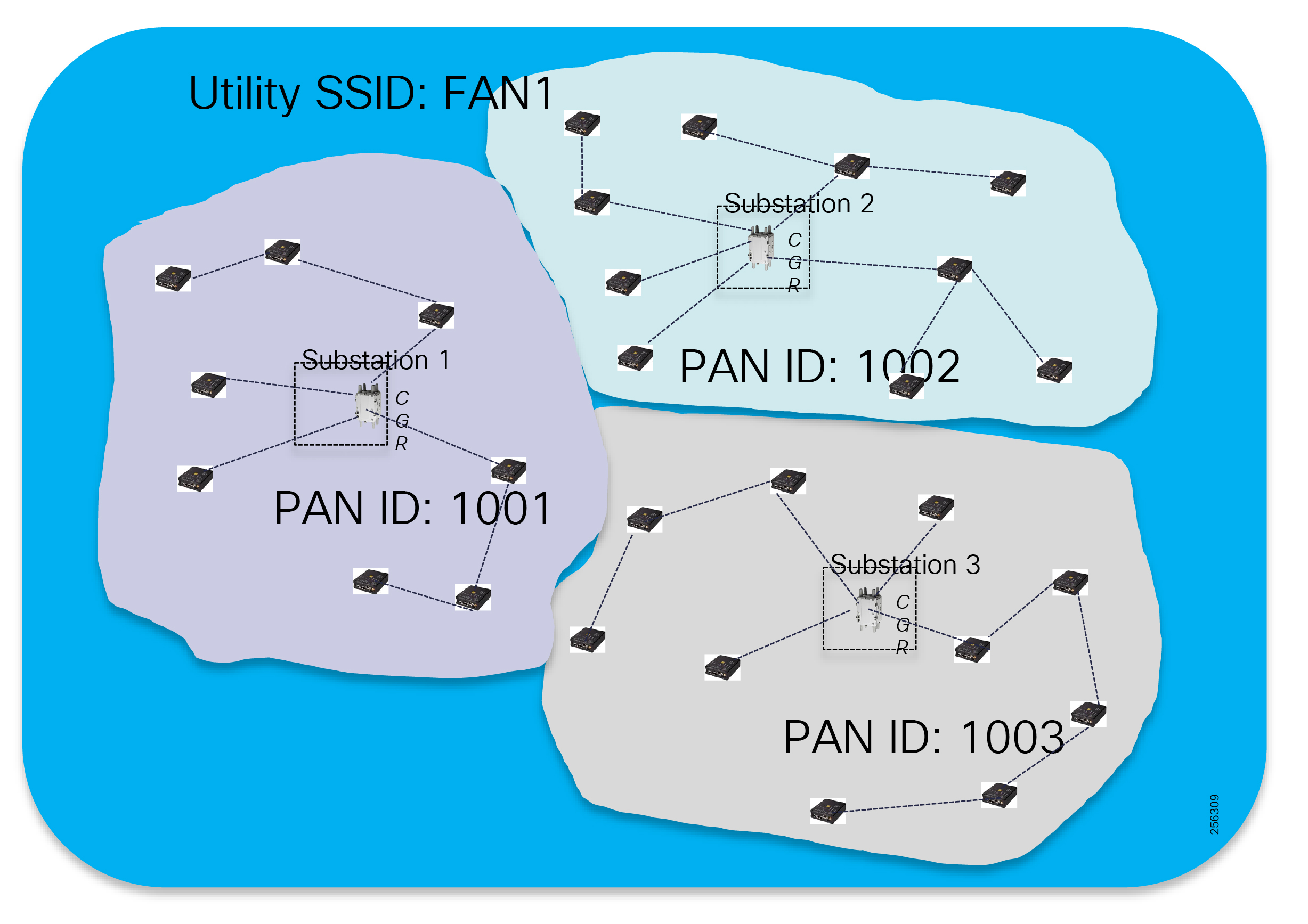
Capacity Planning
The Cisco Resilient Mesh products radio interfaces are half-duplex, meaning that the communication between two devices is uni-directional. Sending and receiving data does not occur at the same time.
Figure 156 Half-Duplex Communication
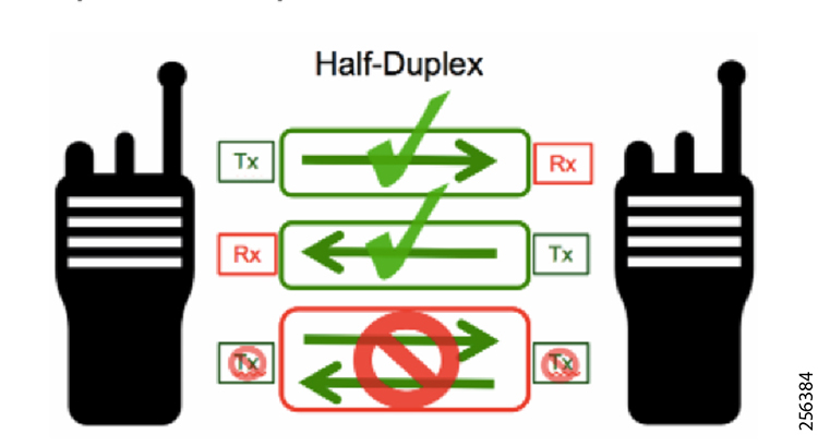
Because of this mode of operation, the end-to-end application throughput is less than the physical data rate. If the application traffic flow needs to travel multiple hops, the throughput will keep decreasing at each hop. It is important that network administrators design the network depth to a reasonable number of hops in order to achieve the desired level of services. The Cisco recommendation is to keep the mesh depth to no more than 4 to 5 hops for DA applications.
Typically, a mesh network is designed for the highest link data rate between each node since the same link could carry traffic from other downstream nodes unless that link is connecting a leaf node and since the mesh dynamic topology that can change due to changes in the RF conditions. For example, a leaf node could become a parent; therefore, its link now will also be an uplink.
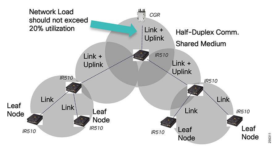
During the network capacity planning phase, network designers should not plan to load the network at more than 20% capacity during steady state. Each aggregation node should not transport more than 20% of the available goodput bandwidth determine during the RF Site Survey phase so that the node is not oversubscribed. This approach will allow the network to operate during peak times, especially when many events are happening in the grid or when the RF environment is experiencing poor performance and the mesh nodes need to perform packet retransmissions.
Always design the first links between the CGR router and the first rank nodes to operate at the highest data rate possible and plan for at least 10 to 15 dB fading margin so that the links will remain stable during RSSI changes. The first links will have the heaviest utilization in the PAN since they are the trunk of the RPL tree.
Figure 158 Design First Links for Highest Data Rate
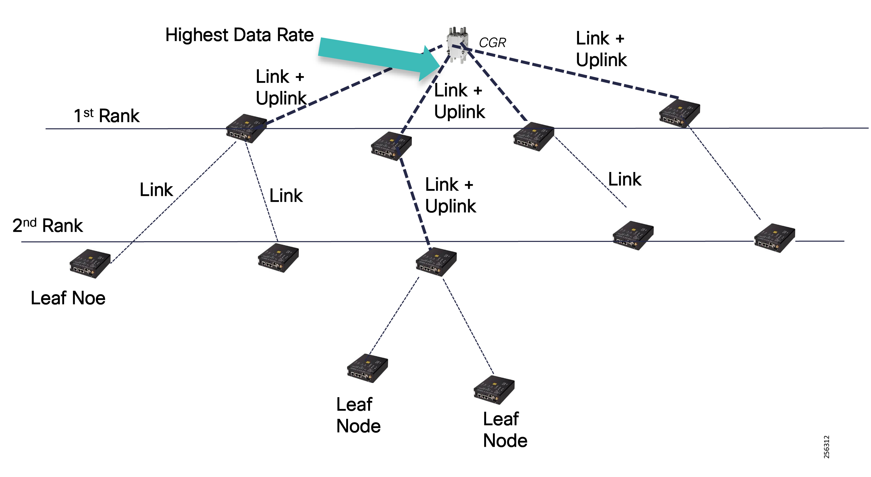
Following this recommendation, network administrators can determine the ratio of children per parent to ensure that there is no oversubscription and that the network has enough remaining capacity to operate during critical electrical grid events. Figure 159 is an example of how to determine the ratio, assuming constant ingress traffic into the mesh from grid devices or downstream nodes. If the ingress traffic from all downstream nodes is not constant, then the ratio of children per parent can be done based on a statistical model that will allow more children per parent or each child could send ingress traffic into the mesh at a higher capacity.
Figure 159 Parent/Children Ratio Example
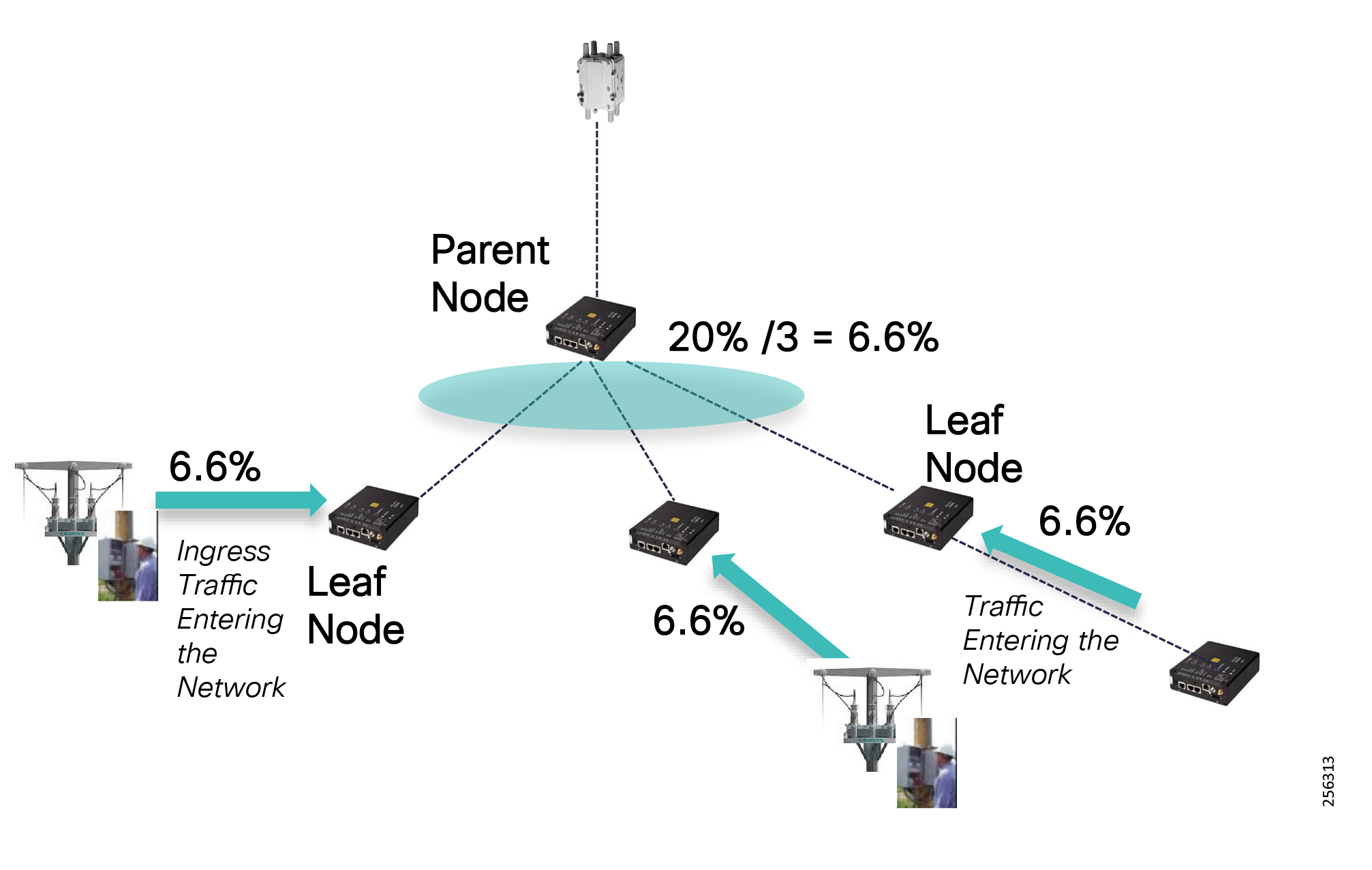
Channel Hopping Schema
The Cisco Resilient Nodes follow a global broadcast channel schedule that is randomly generated by the PAN coordinator, the CGR router. Mesh nodes determine the global broadcast channel schedule and synchronize their local clock from the Information Element (IE) frames.
Each node also randomly generates the Local Unicast Channel Schedule that complies with the FCC regulation and IEEE standard described in ISM Band Overview. Nodes follow this schedule to listen on a specific channel for a given period of time, 125 milliseconds before hopping onto another channel or the broadcast channel. Adjacent nodes determine another node's Unicast Channel schedule and know when and to which channel it can transmit data. This ensures that a node cannot transmit more than 400msec on any given channel within a 20-second period.
Dwell window and max-dwell parameters under the WPAN interface set the transmit limits in order to comply with the regional ISM band regulations. The dwell window defines the measurement period and the maximum dwell time represents the maximum transmit duration within the window period. For US, the dwell window period for the Cisco Resilient Mesh is defined by the number of channel (31 channels) multiplied by 0.4 seconds which totals 12.4 seconds and the max-dwell time is 0.4 seconds.
Because each node has a different unicast channel schedule, multiple nodes can co-exist within the same area and can receive data at the same time instance (multiple transmissions), assuming the channels are not adjacent and at the receiving node, the desired signal is stronger by 15 dB than the undesired signal.
Figure 160 Channel Hopping Schedules
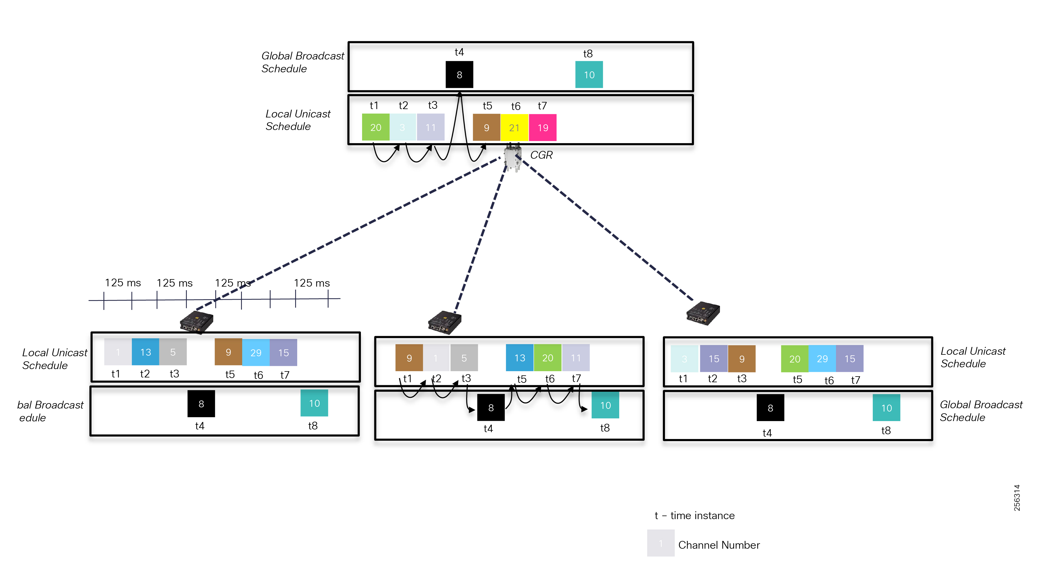
Note: The transmit function has priority over the unicast listening schedule; therefore, when a node has data to transmit, it can skip the listening node state until it reaches the FCC transmit limit. When a node skips the listening state, the adjacent nodes have no way of knowing that the node is not listening anymore and can attempt to send data to the channel the node was supposed to listen. This scenario leads to frame retransmission until the targeted node switches back to the listening unicast schedule.
Channel notching is a feature that lets customers remove certain channels from being used by the unicast scheduler. This feature is useful when some channels have poor performance due to heavy utilization from nearby systems or interference devices. This feature is configured per neighbor on both sides of a link.
Figure 161 Channel Notching List Feature
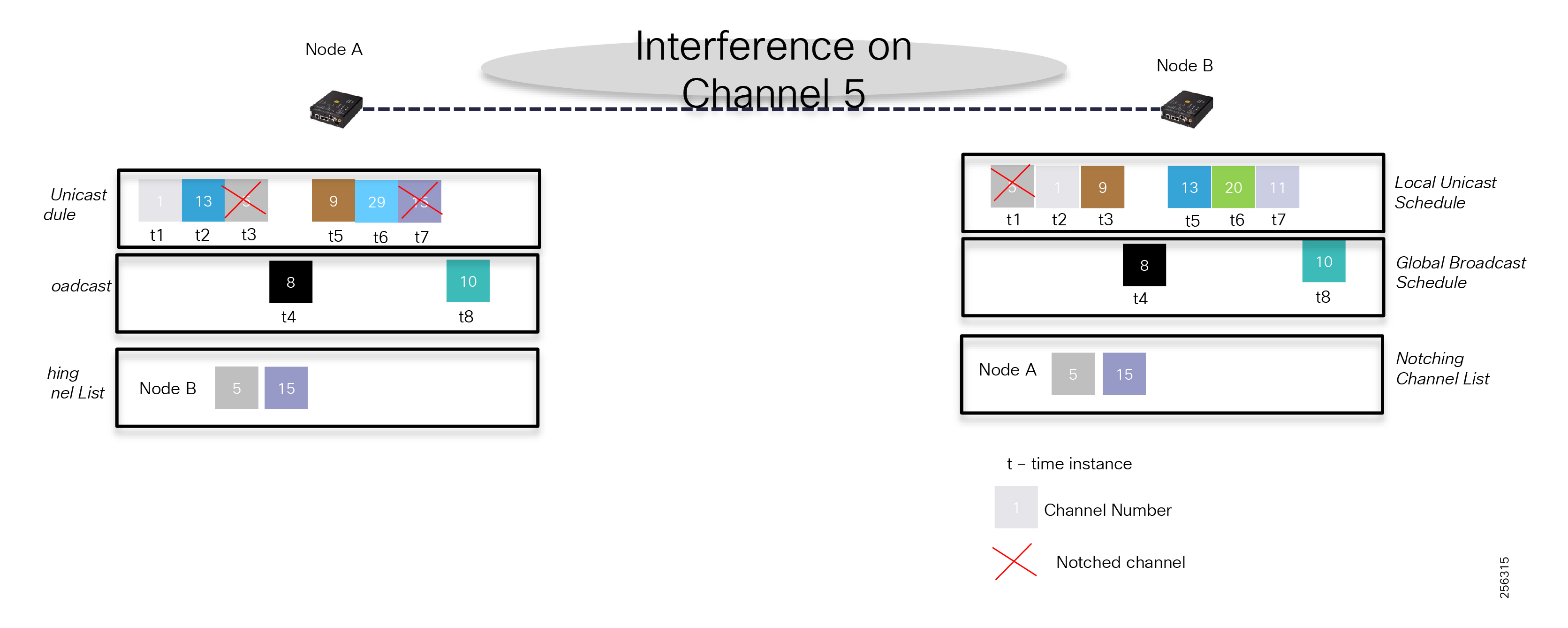
Note: Based on FCC regulation, a node must be configured with at least 25 channels.
Adaptive Data Rate and Adaptive Modulation Considerations
Cisco Resilient Mesh release has brought to the market a unique, innovative solution that customers can leverage for their deployments. Since then, the mesh software was enhanced so that each mesh node can be configured with more than a single, fixed data rate. Network administrators can plan for the network to support up to four data rates and, if the RF link characteristics deteriorate, the software can dynamically change its data rate to a lower rate, which should have a better RSSI margin to maintain connectivity with a neighbor node. The reverse is also true: if RF conditions improve, than the software will dynamically increase the link data rate.
This automatic process of down-shifting or up-shifting the data rate within a certain modulation, like OFDM, is called Adaptive Data Rate (ADR). It is done per packet, meaning every packet carries the OFDM MCS data rate in the physical header and the device interface driver can decode the frame at different data rates. Because the link RF characteristics between two nodes are similar, the nodes will use the same data rate in both directions. So, one can think of the adaptive data rate as a per-link or per-neighbor feature.
At a high level, the ADR feature uses the average link RSSI level and average packet loss rate as thresholds to determine when to change the data rate.
Figure 162 Adaptive Rate Feature
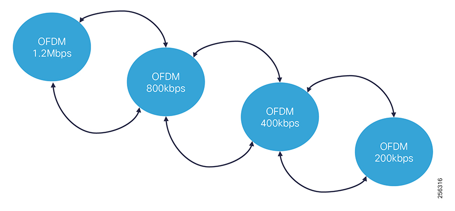
This feature can come in handy for deployments that lack the initial node density and when customers are looking to quickly deploy DA applications in specific parts of an area. The initial RF network design can be done based on a lower data rate, for example 200Kbps, which should allow for greater link distances between nodes. This gives customers deployment agility to address feeders with poor performance first. Over time, the area will have enough density for the RF design to be changed so that the links operate at a higher data rate, therefore higher capacity.
|
|
|
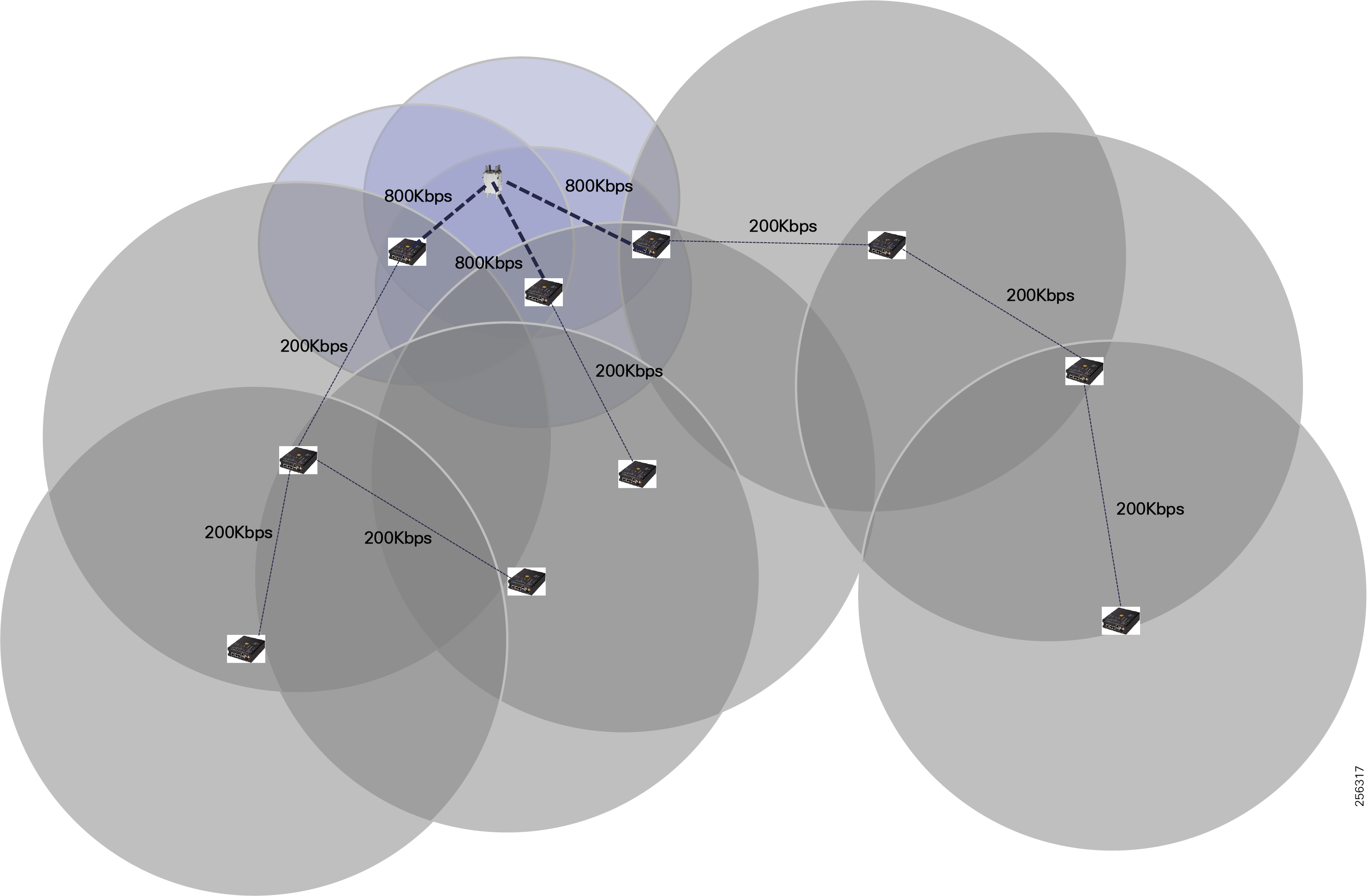

Adaptive data rate can also help during temporary space obstruction between two nodes. For example, let's say a delivery truck is parked between two nodes. The software will down-shift to a lower data rate in order to maintain connectivity. This is a trade-off between available performance and network availability. If the link happened to be an uplink also, then the nodes will experience congestion, but QoS will ensure that priority traffic will be sent first ahead of non-critical traffic.
Figure 163 Normal Conditions and Temporary Path Obstruction
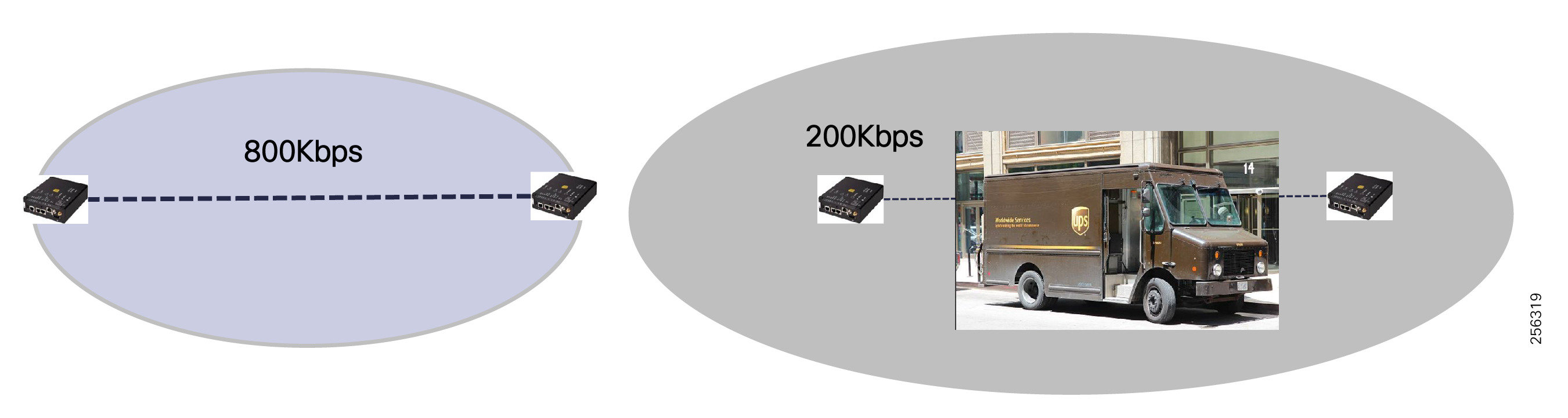
Another scenario where customers can benefit from AR is with leaf nodes that are connected to grid assets (example: end-of-line meters) that don't require fast data rates. During the RF design phase, customer can engineer these links to operate at a lower data rate.
Figure 164 Lower Data Rate for Lead Nodes
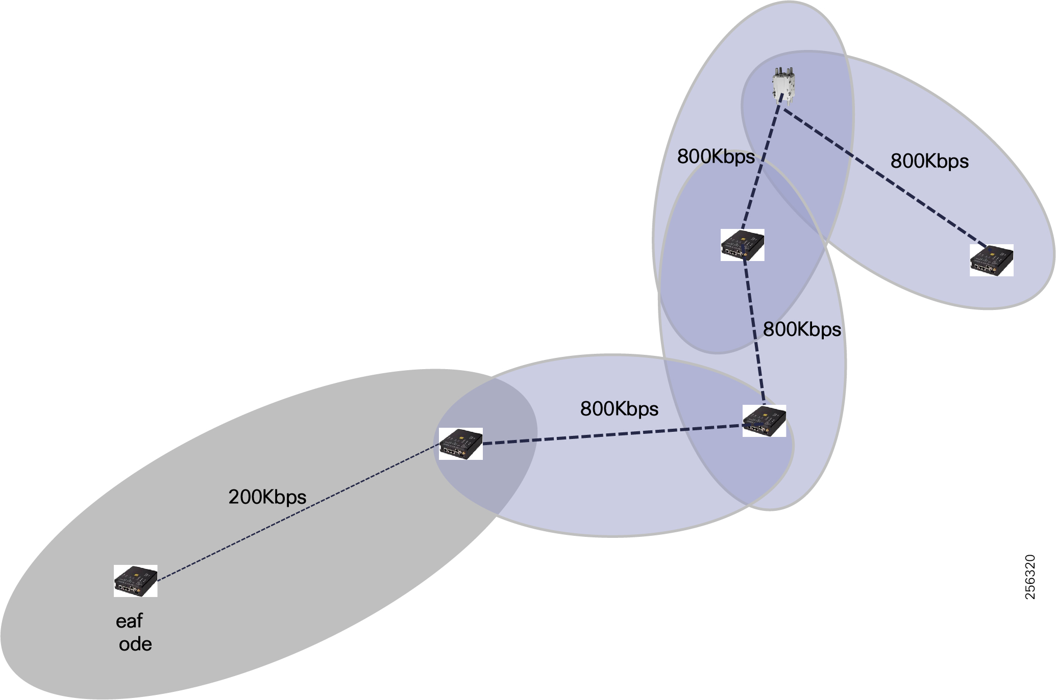
Customers should avoid mixing link data rates on aggregation nodes to avoid performance issues. When an aggregation node has some children that operate at 800Kbps data rate and others at 200Kbps, the children with faster data rate could become stuck behind longer transmission from the slower children.
The Cisco Resilient Mesh also supports Adaptive Modulation, which will allow devices to change a link modulation from OFDM modulation to FSK modulation and vice versa.
Figure 165 Adaptive Modulation Feature
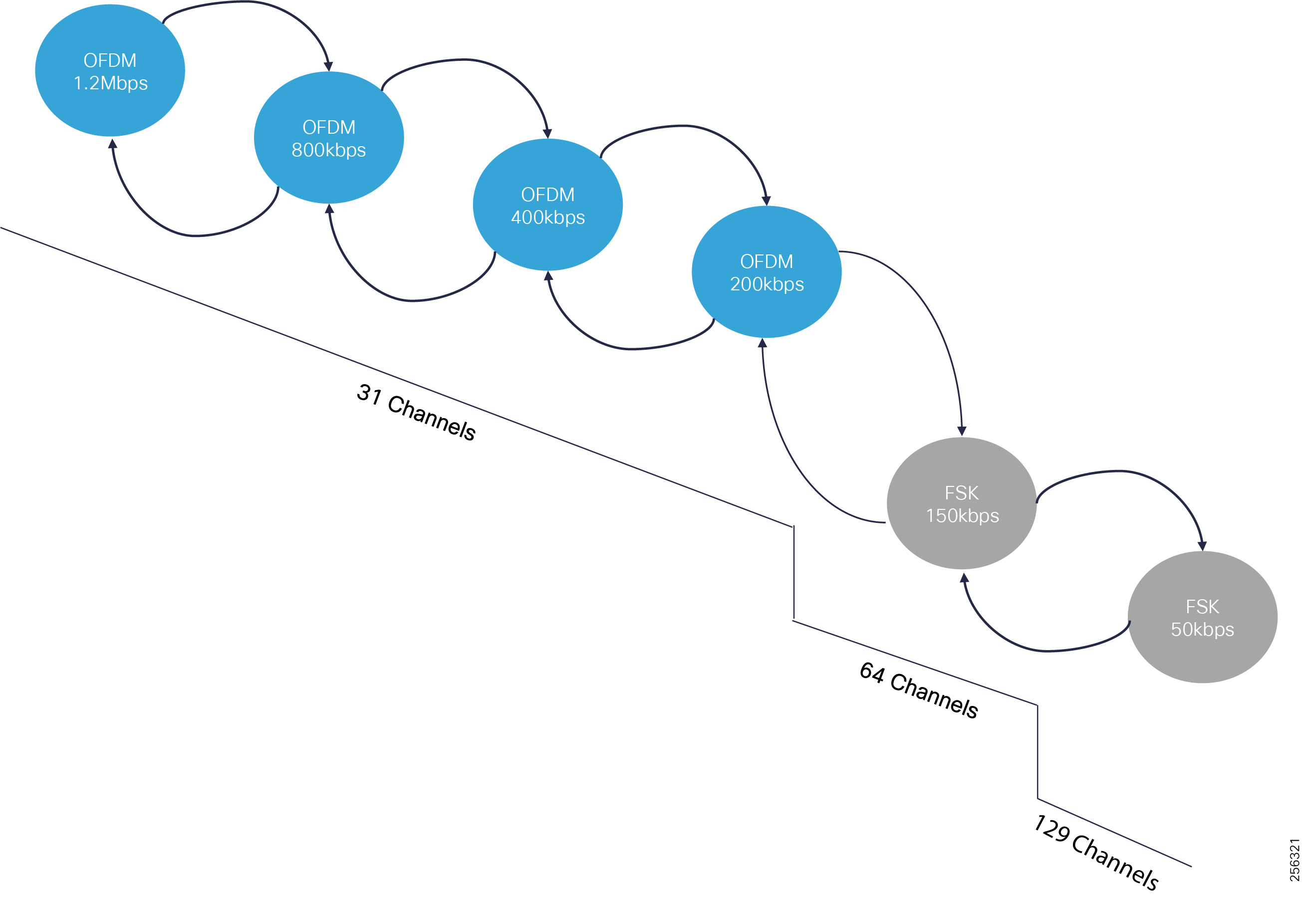
This allows Cisco Resilient Mesh to be backward compatible with existing AMI deployments based on Cisco CG-Mesh and allow for a true multi-service solution for DA, AMI, DER, etc.
Resilient Mesh Performance
RF Link and Path Performance
The Cisco Resilient Mesh has been enhanced to perform faster physical transmission data rates based on the IEEE 802.15.4g/e Option 2 profile using OFDM modulation. At the time of this writing, the software supports five out of the seven modulation data rates specified in the standard. Cisco will support the remaining data rate in the upcoming software releases without requiring any hardware upgrades.
The transmit power varies across the different OFDM data rates; the higher the data rate, the less transmit power is used in order to comply with the FCC regulations. Therefore, the link area of coverage will be smaller for the lower data rates. This is an important aspect that should be considered during the RF design planning, especially if customers are implementing Adaptive Data Rates and Adaptive Modulation, as described in Adaptive Data Rate and Adaptive Modulation Considerations.
Note: The transmit power cannot be changed by customers.
Note: The RSSI for 10% Packet Error Rate (PER) it was captured at a normal temperature of 77° F/ 25° C and it will vary by few units in region with extreme temperatures.
|
|
|
|
|
|
|
|
|
|
All OFDM physical data rates use the same channel plan structure with 31 channels, where the Channel Hopping Scheduler randomly hops across them based on the FCC regulations described in RF Design Considerations.
|
|
|
|
|
|
The Cisco Resilient Mesh also supports lower data rates based on Frequency Shifting Keying (FSK) for backward compatibility for the initial AMI and DA deployments based on the IR509 and IR529.
Note: A lower OFDM data rate is better than a higher FSK data rate because of the advanced encoding schema that OFDM uses that carries redundant data across sub-carriers within a channel. To enable data redundancy within FSK modulation, administrators must enable FSK FEC, which reduces the data rate in a half.
|
|
|
|
|
|
|
|
|
The Resilient Mesh also supports a very low data rate based on the Offset Quadrature Phase-Shift Keying (OQPSK) modulation that can be uses for sensor data collection.
|
|
lation |
|
|
|
|
|
|
ation PHY Mode |
One Link Performance Testing (Reference Results)
The link performances between two devices can greatly vary based on the RF conditions. When testing performance, it is important to detail the conditions in which the test took place. For example, a test performed using the same link RSSI values between two nodes will have different results when the noise floor differs or if there is a device that interfere in the vicinity, or if one test is performed during a sunny day versus a rainy day. Figure 166 shows the test results performed during internal lab validation and gives network designers a sense of the application throughput between two nodes. The testing was performed in various conducted environments using coax cabling over a good quality link (RSSI = ~70 dBm), low noise floor conditions (-120 dBm), and no external interference. A UDP data stream was sent from one node to another using different packet sizes: 64B, 256B, 512B, and 1300 Bytes and the maximum throughput between the nodes was recorded at which the Packet Error Rate (PER) < 1%.
Figure 166 Link Performance Test Topology
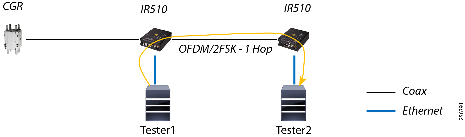
The one-way latency across the link varies based on the link data rate. The higher the data rate, the less time it takes for a frame to be transmitted over the air. Table 74 captures the average latency for sending a stream with different packet sizes for 10 seconds from one node to another over the same link conditions as the previous throughput testing.
The link latency will vary if a node has multiple parents since the RF link characteristics will change with each parent link. Also, if one parent link is experiencing congestion or interference, the child node will retransmit the packet multiple times using different Back-off timers, based on the priority of the packet as discussed in Figure 87; therefore, latency to transmit one packet will increase.
Path, Multi-hop Throughput Performance Testing (Reference Results)
The same RF environmental conditions used in the Link performance testing were used to determine the mesh path performances over multiple hops: OFDM - 5 links and FSK - 2 links.
This type of testing was done to baseline the mesh performance for DA FLISR use case if the Grid vendor solution requires peer-to-peer communication between the reclosers.
Figure 168 Path Performance Test Topology
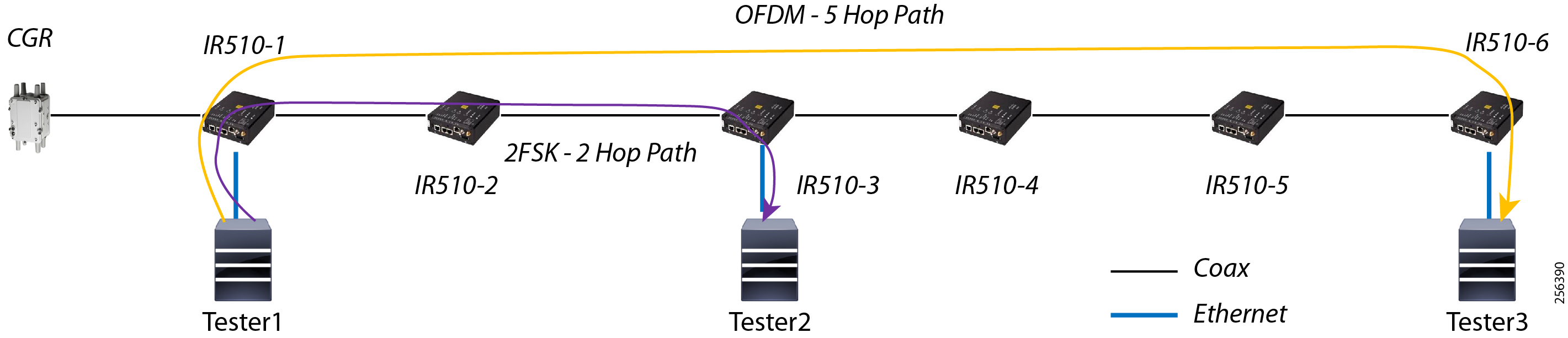
DA Feeder Automation using Cellular Service (3G/4G) Solution
This chapter includes the following major topics:
■![]() Important Features Supported by LTE Pluggable Modules
Important Features Supported by LTE Pluggable Modules
■![]() Distribution Automation Architecture using Cellular Backhaul
Distribution Automation Architecture using Cellular Backhaul
■![]() Cellular Backhaul Design Considerations
Cellular Backhaul Design Considerations
Cellular backhaul will be the most prevalent deployment backhaul and the new Cisco IR1101 platform will be the correct choice for deploying as a DA Gateway. However, the Cisco IR807 could be deployed in cases where lower cost and lower power consumption are the primary requirements. The CGR 1120 platform will suit for Dual LTE backhaul DA Gateway deployments.
Cisco DA Gateways supports a Cellular-pluggable module that supports the following 4G/3G modes:
■![]() 4G LTE—4G LTE mobile specification provides multi-megabit bandwidth, more efficient radio network, latency reduction, and improved mobility. LTE solutions target new cellular networks. These networks initially support up to 100 Mb/s peak rates in the downlink and up to 50 Mb/s peak rates in the uplink. The throughput of these networks is higher than the existing 3G networks
4G LTE—4G LTE mobile specification provides multi-megabit bandwidth, more efficient radio network, latency reduction, and improved mobility. LTE solutions target new cellular networks. These networks initially support up to 100 Mb/s peak rates in the downlink and up to 50 Mb/s peak rates in the uplink. The throughput of these networks is higher than the existing 3G networks
■![]() 3G Evolution High-Speed Packet Access (HSPA/HSPA+)—HSPA is a UMTS-based 3G network. It supports High-Speed Downlink Packet Access (HSDPA) and High-Speed Uplink Packet Access (HSUPA) data for improved download and upload speeds. Evolution High-Speed Packet Access (HSPA+) supports Multiple Input/Multiple Output (MIMO) antenna capability.
3G Evolution High-Speed Packet Access (HSPA/HSPA+)—HSPA is a UMTS-based 3G network. It supports High-Speed Downlink Packet Access (HSDPA) and High-Speed Uplink Packet Access (HSUPA) data for improved download and upload speeds. Evolution High-Speed Packet Access (HSPA+) supports Multiple Input/Multiple Output (MIMO) antenna capability.
■![]() 3G Evolution-Data Optimized (EVDO or DOrA) Mode—EVDO is a 3G telecommunications standard for the wireless transmission of data through radio signals, typically for broadband Internet access. DOrA refers to EVDO Rev-A. EVDO uses multiplexing techniques including Code Division Multiple Access (CDMA), as well as Time Division Multiple Access (TDMA), to maximize both individual users' throughput and the overall system throughput.
3G Evolution-Data Optimized (EVDO or DOrA) Mode—EVDO is a 3G telecommunications standard for the wireless transmission of data through radio signals, typically for broadband Internet access. DOrA refers to EVDO Rev-A. EVDO uses multiplexing techniques including Code Division Multiple Access (CDMA), as well as Time Division Multiple Access (TDMA), to maximize both individual users' throughput and the overall system throughput.
For more details about other supported TDD LTE, UMTS, HSPA+ and HSPA bands, please refer to product specification documentation at the following URL:
■![]() https://www.cisco.com/c/en/us/td/docs/routers/access/1101/hardware/installation/guide/1101hwinst/pview.html#12287
https://www.cisco.com/c/en/us/td/docs/routers/access/1101/hardware/installation/guide/1101hwinst/pview.html#12287
■![]() https://www.cisco.com/c/en/us/td/docs/routers/connectedgrid/cgr1000/ios/modules/4g_lte/b_4g_cgr1000.html
https://www.cisco.com/c/en/us/td/docs/routers/connectedgrid/cgr1000/ios/modules/4g_lte/b_4g_cgr1000.html
■![]() https://www.cisco.com/c/en/us/td/docs/routers/access/800/807/software/configuration/guide/b_IR807_config/b_IR807_config_chapter_011.html
https://www.cisco.com/c/en/us/td/docs/routers/access/800/807/software/configuration/guide/b_IR807_config/b_IR807_config_chapter_011.html
For details about wireless antenna positioning guidelines, you can refer to the following document.
■![]() https://www.cisco.com/c/en/us/td/docs/routers/access/1101/hardware/installation/guide/1101hwinst/pview.html#12287
https://www.cisco.com/c/en/us/td/docs/routers/access/1101/hardware/installation/guide/1101hwinst/pview.html#12287
Important Features Supported by LTE Pluggable Modules
■![]() Dual SIM, which allows SIM to be active in either slot; failover to the alternative SIM slot if the active SIM loses connectivity to the network
Dual SIM, which allows SIM to be active in either slot; failover to the alternative SIM slot if the active SIM loses connectivity to the network
■![]() Auto SIM mode, which will automatically select the right carrier after a SIM slot switching and automatically reset the modem
Auto SIM mode, which will automatically select the right carrier after a SIM slot switching and automatically reset the modem
■![]() SIM Online Insertion and Removal (OIR)
SIM Online Insertion and Removal (OIR)
■![]() SIM lock and unlock capabilities
SIM lock and unlock capabilities
■![]() IPv6 protocol is supported on the cellular interface to enable LTE IPv6 data connection
IPv6 protocol is supported on the cellular interface to enable LTE IPv6 data connection
Distribution Automation Architecture using Cellular Backhaul
The DA application bidirectional flow can be classified as follows:
Cellular Backhaul will suit for second flow; i.e., SCADA -----> IEDs
Figure 169 depicts a solution architecture where IEDs can directly communicate with the centralized SCADA. In this design, DA Gateways directly connect to HER in the regional control center via public WAN connectivity. For redundancy design, DA Gateways can have two active/active tunnels to two different regional Control Centers. DA application traffic and NMS control traffic can flow in the same FlexVPN tunnel.
For more details, refer to the Distribution Automation - Secondary Substation Design Guide at the following URL:
■![]() https://www.cisco.com/c/en/us/td/docs/solutions/Verticals/Distributed-Automation/Secondary-Substation/DG/DASS-DG.pdf
https://www.cisco.com/c/en/us/td/docs/solutions/Verticals/Distributed-Automation/Secondary-Substation/DG/DASS-DG.pdf
Figure 169 SCADA to IED Traffic Flow
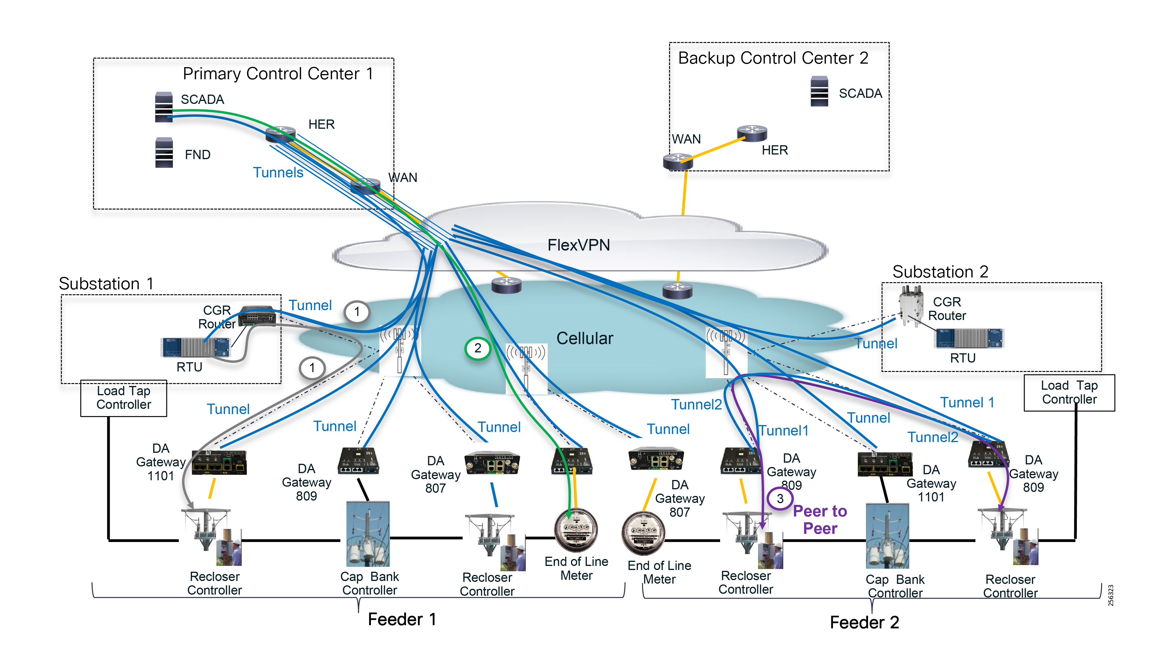
Cellular Backhaul Design Considerations
■![]() Bandwidth is generally shared between many users (such as smartphones, smart meters, and M2M) when attached to the same base station. This makes it difficult to design a network with guaranteed bandwidth, latency, and QoS parameters for meeting any performance-based criteria.
Bandwidth is generally shared between many users (such as smartphones, smart meters, and M2M) when attached to the same base station. This makes it difficult to design a network with guaranteed bandwidth, latency, and QoS parameters for meeting any performance-based criteria.
■![]() Bandwidth is asymmetric since the services are designed to offer greater download speed to smartphone users. Conversely, FAN traffic profiles have either symmetrical or greater upstream speed requirements, which requires evaluating the traffic load when designing the network. This means using a network protocol to understand the link capacity and potential costs (dependent on service subscription tariffs).
Bandwidth is asymmetric since the services are designed to offer greater download speed to smartphone users. Conversely, FAN traffic profiles have either symmetrical or greater upstream speed requirements, which requires evaluating the traffic load when designing the network. This means using a network protocol to understand the link capacity and potential costs (dependent on service subscription tariffs).
■![]() Coverage and network availability must be evaluated for rural zones with isolated devices.
Coverage and network availability must be evaluated for rural zones with isolated devices.
■![]() Cellular deployments only offer native IPv4 services and if IPv6 connectivity is required, IPv6 traffic must be tunneled over GRE/IPv4.
Cellular deployments only offer native IPv4 services and if IPv6 connectivity is required, IPv6 traffic must be tunneled over GRE/IPv4.
Glossary
The following table lists the acronyms and initialisms used in this document.j
|
|
|
|
|
|
|
|
|
|
|
|
|
|
|
|
|
|
|
|
|
|
|
|
|
|
|
|
|
|
|
|
|
|
|
|
|
|
|
|
|
|
|
|
|
|
|
|
|
|
|
|
|
|
|
|
|
|
|
|
|
|
|
|
|
|
 Feedback