Rack-Mount the Chassis

Unpack and Inspect the Chassis


Tip


Keep the shipping container in case the chassis requires shipping in the future. If any internal components fail, you must send your chassis back to us for RMA.


Note


The chassis is thoroughly inspected before shipment. If any damage occurred during transportation or any items are missing, contact your customer service representative immediately.


See Package Contents for a list of what shipped with the chassis.

Procedure


Step 1

Remove the chassis from its cardboard container and save all packaging material.

Step 2

Compare the shipment to the equipment list provided by your customer service representative. Verify that you have all items.

Step 3

Check for damage and report any discrepancies or damage to your customer service representative. Have the following information ready:

  • Invoice number of shipper (see the packing slip)

  • Model and serial number of the damaged unit. See Serial Number Locations for the location of the serial number.

  • Description of damage

  • Effect of damage on the installation


Rack-Mount the Chassis

Before you begin

You can install the chassis in a rack using the Cisco rack kit (part number 800-43376-02).

The rack must be of the following type:

  • A standard 19-inch (48.3-cm) wide, 4-post EIA rack with mounting posts that conform to English universal hole spacing per section 1 of ANSI/EIA-310-D-1992.

  • The rack post holes can be square 0.38-inch (9.6 mm), round 0.28-inch (7.1 mm), #12-24 UNC, or #10-32 UNC when you use the supplied slide rails.

  • The minimum vertical rack space per appliance must be 1 RU, equal to 1.75 inches (44.45 mm).

  • The slide rails for the chassis have an adjustment range of 24 to 36 inches (610 to 914 mm).


Note


The slide rails that ship with the chassis do not require tools for installation if you install them in a rack that has square 0.38-inch (9.6 mm), round 0.28-inch (7.1 mm), or #12-24 UNC threaded holes.


Safety Warnings
Take note of the following warning:

Warning


Statement 1006—Chassis Warning for Rack-Mounting and Servicing

To prevent bodily injury when mounting or servicing this unit in a rack, you must take special precautions to ensure that the system remains stable. The following guidelines are provided to ensure your safety:

  • This unit should be mounted at the bottom of the rack if it is the only unit in the rack.

  • When mounting this unit in a partially filled rack, load the rack from the bottom to the top with the heaviest component at the bottom of the rack.

  • If the rack is provided with stabilizing devices, install the stabilizers before mounting or servicing the unit in the rack.


Warning


Statement 1032—Lifting the Chassis

To prevent personal injury or damage to the chassis, never attempt to lift or tilt the chassis using the handles on modules, such as power supplies, fans, or cards. These types of handles are not designed to support the weight of the unit.


Warning


Statement 1098—Lifting Requirement

Two people are required to lift the heavy parts of the product. To prevent injury, keep your back straight and lift with your legs, not your back.


Procedure


Step 1

Attach the inner rails to the sides of the chassis:

  1. Align an inner rail with one side of the chassis so that the three keyed slots in the rail align with the three pegs on the side of the chassis.

  2. Set the keyed slots over the pegs, and then slide the rail toward the front to lock it in place on the pegs. The front slot has a metal clip that locks over the front peg.

  3. Install the second inner rail to the opposite side of the chassis.

Figure 1. Attach the Inner Rail to the Side of the Chassis

1

Front of chassis

2

Locking clip on inner rail

Step 2

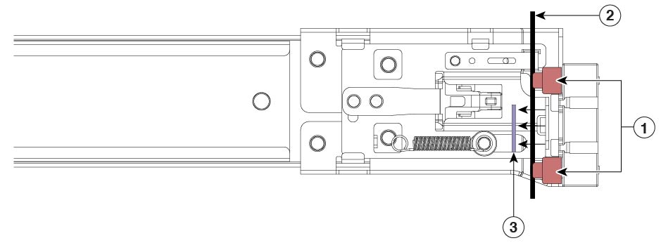
Open the front securing plate on both slide-rail assemblies. The front end of the slide-rail assembly has a spring-loaded securing plate that must be open before you can insert the mounting pegs into the rack-post holes.

On the outside of the assembly, push the green arrow button toward the rear to open the securing plate.

Figure 2. Front Securing Mechanism on the Inside of Front End

1

Front mounting pegs

2

Rack post

3

Securing plate shown pulled back to open position

Step 3

Install the slide rails into the rack:

  1. Align one slide-rail assembly front end with the front rack-post holes that you want to use.

    The slide rail front end wraps around the outside of the rack post and the mounting pegs enter the rack-post holes from the outside-front.

    Note


    The rack post must be between the mounting pegs and the open securing plate.

  2. Push the mounting pegs into the rack-post holes from the outside-front.

  3. Press the securing plate release button, marked “PUSH.” The spring-loaded securing plate closes to lock the pegs in place.

  4. Attach the second slide-rail assembly to the opposite side of the rack. Make sure that the two slide-rail assemblies are at the same height with each other and are level front-to-back.

  5. Pull the inner slide rails on each assembly out toward the rack front until they hit the internal stops and lock in place.

Step 4

Insert the chassis into the slide rails:

  1. Align the rear of the inner rails that are attached to the chassis sides with the front ends of the empty slide rails on the rack.

  2. Push the inner rails into the slide rails on the rack until they stop at the internal stops.

  3. Slide the release clip toward the rear on both inner rails, and then continue pushing the chassis into the rack until its front slam latches engage with the rack posts

Figure 3. Inner Rail Release Clip

1

Inner rail release clip

2

Inner rail attached to chassis and inserted into outer rail

3

Outer rail attached to rack post

Step 5

(Optional) Secure the chassis in the rack more permanently by using the two screws that are provided with the slide rails. Perform this step if you plan to move the rack with chassis installed. With the chassis fully pushed into the slide rails, open a hinged slam latch lever on the front of the chassis and insert the screw through the hole that is under the lever. The screw threads into the static part of the rail on the rack post and prevents the chassis from being pulled out. Repeat for the opposite slam latch.


What to do next

Install the cables according to your default software configuration as described in the Getting Started Guide for your software version.