How Remote Management Works
To allow the management center to manage the threat defense over the internet, use the outside interface for management center manager access instead of the Management interface. Because most remote branch offices only have a single internet connection, outside manager access makes centralized management possible.
 Note |
The management connection is a secure, TLS-1.3-encrypted communication channel between itself and the device. You do not need to run this traffic over an additional encrypted tunnel such as Site-to-Site VPN for security purposes. If the VPN goes down, for example, you will lose your management connection, so we recommend a simple management path. |
Registration Methods
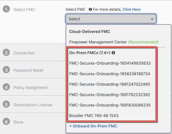
Use one of the following methods to provision your threat defense:
Zero-Touch Provisioning (Management Center 7.4 and later, Threat Defense 7.2 and later)
-
Send the threat defense to the remote branch office. Do not configure anything on the device, because zero-touch provisioning may not work with pre-configured devices.
Note
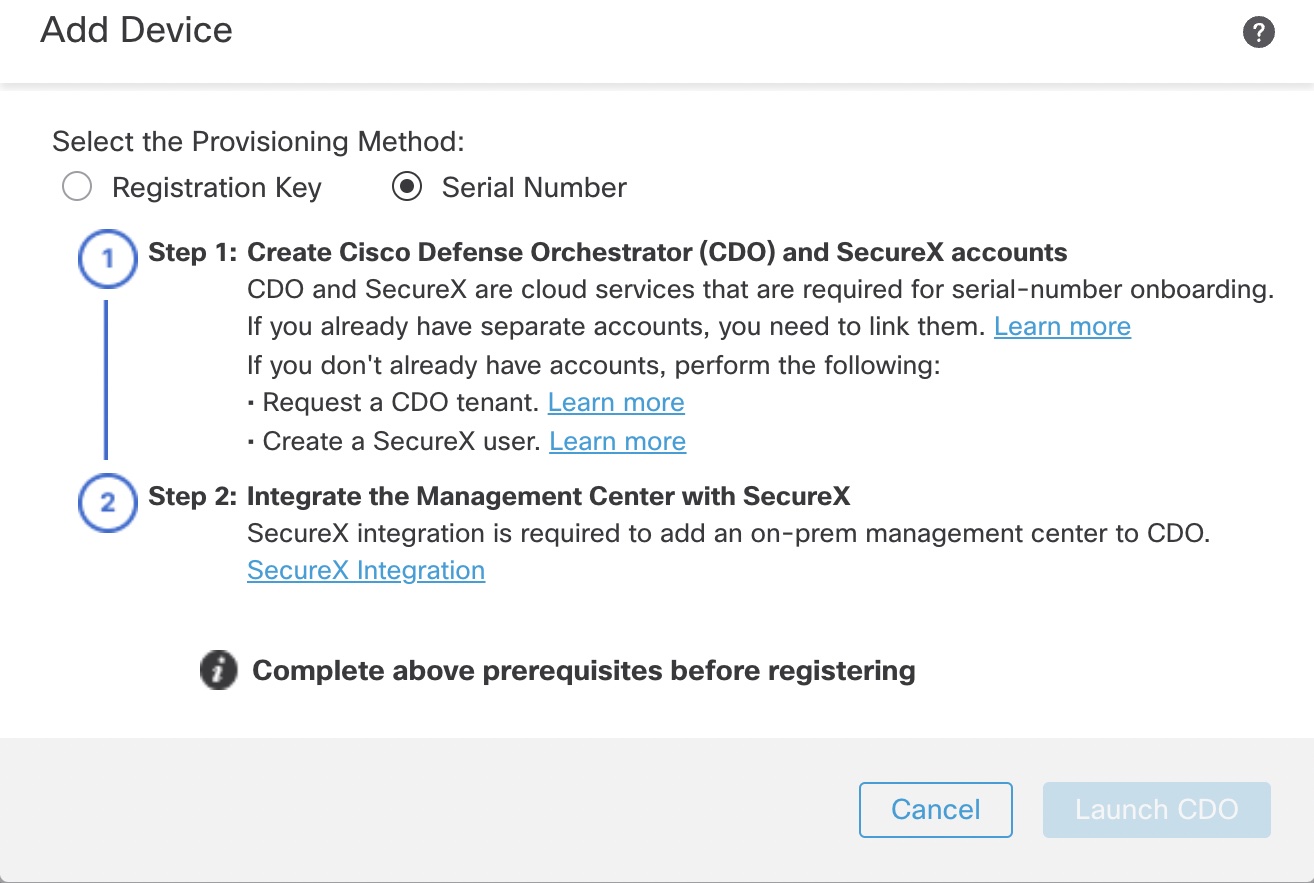
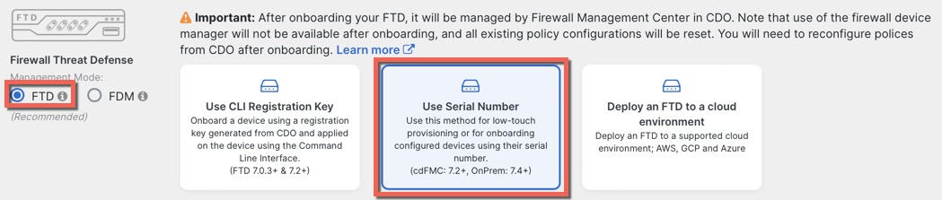
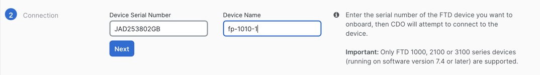
You can preregister the threat defense on the management center using the threat defense serial number before sending the device to the branch office. The management center integrates with the Cisco Security Cloud and CDO for this functionality.
-
At the branch office, cable and power on the threat defense.
-
Finish registering the threat defense using the CDO.
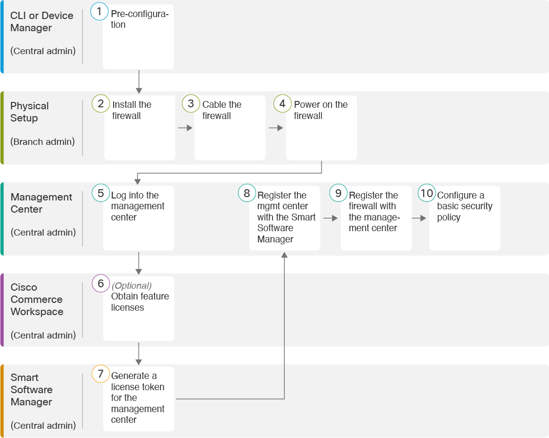
Manual Provisioning
-
Pre-configure the threat defense at the CLI or using the device manager, and then send the threat defense to the remote branch office.
-
At the branch office, cable and power on the threat defense.
-
Finish registering the threat defense using the management center.
Threat Defense Manager Access Interface
This guide covers outside interface access because it is the most likely scenario for remote branch offices. Although manager access occurs on the outside interface, the dedicated Management interface is still relevant. The Management interface is a special interface configured separately from the threat defense data interfaces, and it has its own network settings.
-
The Management interface network settings are still used even though you are enabling manager access on a data interface.
-
All management traffic continues to be sourced from or destined to the Management interface.
-
When you enable manager access on a data interface, the threat defense forwards incoming management traffic over the backplane to the Management interface.
-
For outgoing management traffic, the Management interface forwards the traffic over the backplane to the data interface.
Manager Access Requirements
Manager access from a data interface has the following limitations:
-
You can only enable manager access on a physical, data interface. You cannot use a subinterface or EtherChannel, nor can you create a subinterface on the manager access interface. You can also use the management center to enable manager access on a single secondary interface for redundancy.
-
This interface cannot be management-only.
-
Routed firewall mode only, using a routed interface.
-
PPPoE is not supported. If your ISP requires PPPoE, you will have to put a router with PPPoE support between the threat defense and the WAN modem.
-
The interface must be in the global VRF only.
-
SSH is not enabled by default for data interfaces, so you will have to enable SSH later using the management center. Because the Management interface gateway will be changed to be the data interfaces, you also cannot SSH to the Management interface from a remote network unless you add a static route for the Management interface using the configure network static-routes command.
High Availability Requirements
When using a data interface with device high availability, see the following requirements.
-
Use the same data interface on both devices for manager access.
-
Redundant manager access data interface is not supported.
-
You cannot use DHCP; only a static IP address is supported. Features that rely on DHCP cannot be used, including DDNS and zero-touch provisioning.
-
Have different static IP addresses in the same subnet.
-
Use either IPv4 or IPv6; you cannot set both.
-
Use the same manager configuration (configure manager add command) to ensure that the connectivity is the same.
-
You cannot use the data interface as the failover or state link.
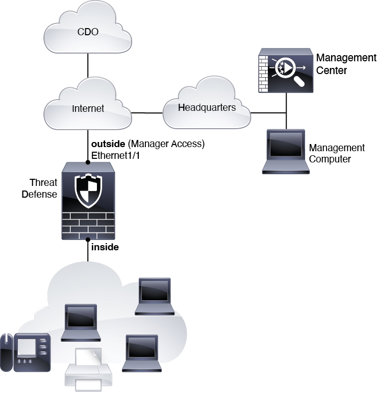
Zero-Touch Provisioning Network
The following figure shows a typical network deployment for the firewall where:
-
The management center is at central headquarters.
-
The threat defense uses the outside interface for manager access.
-
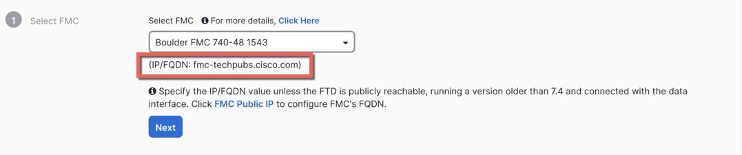
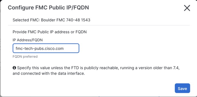
Either the threat defense or management center needs a public IP address or hostname to allow the inbound management connection, although you do not need to know the IP address for registration. For pre-7.2(4) and 7.3 threat defense versions, the management center needs to be publicly reachable.
-
Both the management center and threat defense initially communicate with the Cisco Security Cloud and CDO to establish the management connection
-
After initial establishment, CDO is used to reestablish the management connection if it is disrupted; for example, if the threat defense IP address changes due to a new DHCP assignment, CDO will inform the management center of the change.
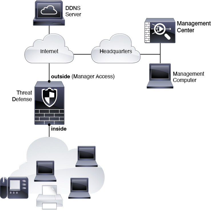
Manual Provisioning Network
The following figure shows a typical network deployment for the firewall where:
-
The management center is at central headquarters.
-
The threat defense uses the outside interface for manager access.
-
Either the threat defense or management center needs a public IP address or hostname to allow to allow the inbound management connection; you need to know this IP address for initial setup. You can also optionally configure Dynamic DNS (DDNS) for the outside interface to accommodate changing DHCP IP assignments.


 ).
).


 )
)
 Feedback