Policy Based Routing

This chapter describes how to configure the ASA to support policy based routing (PBR). The following sections describe policy based routing, guidelines for PBR, and configuration for PBR.

About Policy Based Routing

Traditional routing is destination-based, meaning packets are routed based on destination IP address. However, it is difficult to change the routing of specific traffic in a destination-based routing system. With Policy Based Routing (PBR), you can define routing based on criteria other than destination network—PBR lets you route traffic based on source address, source port, destination address, destination port, protocol, or a combination of these.

Policy Based Routing:

  • Lets you provide Quality of Service (QoS) to differentiated traffic.

  • Lets you distribute interactive and batch traffic across low-bandwidth, low-cost permanent paths and high-bandwidth, high-cost switched paths.

  • Allows Internet service providers and other organizations to route traffic originating from various sets of users through well-defined Internet connections.

Policy Based Routing can implement QoS by classifying and marking traffic at the network edge, and then using PBR throughout the network to route marked traffic along a specific path. This permits routing of packets originating from different sources to different networks, even when the destinations are the same, and it can be useful when interconnecting several private networks.

Why Use Policy Based Routing?

Consider a company that has two links between locations: one a high-bandwidth, low-delay expensive link, and the other a low-bandwidth, higher-delay, less-expensive link. While using traditional routing protocols, the higher-bandwidth link would get most, if not all, of the traffic sent across it based on the metric savings obtained by the bandwidth and/or delay (using EIGRP or OSPF) characteristics of the link. PBR allows you to route higher priority traffic over the high-bandwidth/low-delay link, while sending all other traffic over the low-bandwidth/high-delay link.

Some applications of policy based routing are:

Equal-Access and Source-Sensitive Routing

In this topology, traffic from HR network & Mgmt network can be configured to go through ISP1 and traffic from Eng network can be configured to go through ISP2. Thus, policy based routing enables the network administrators to provide equal-access and source-sensitive routing, as shown here.

Quality of Service

By tagging packets with policy based routing, network administrators can classify the network traffic at the perimeter of the network for various classes of service and then implementing those classes of service in the core of the network using priority, custom or weighted fair queuing (as shown in the figure below). This setup improves network performance by eliminating the need to classify the traffic explicitly at each WAN interface in the core of backbone network.

Cost Saving

An organization can direct the bulk traffic associated with a specific activity to use a higher-bandwidth high-cost link for a short time and continues basic connectivity over a lower-bandwidth low-cost link for interactive traffic by defining the topology, as show here.

Load Sharing

In addition to the dynamic load-sharing capabilities offered by ECMP load balancing, network administrators can now implement policies to distribute traffic among multiple paths based on the traffic characteristics.

As an example, in the topology depicted in the Equal-Access Source Sensitive Routing scenario, an administrator can configure policy based routing to load share the traffic from HR network through ISP1 and traffic from Eng network through ISP2.

Implementation of PBR

The ASA uses ACLs to match traffic and then perform routing actions on the traffic. Specifically, you configure a route map that specifies an ACL for matching, and then you specify one or more actions for that traffic. Finally, you associate the route map with an interface where you want to apply PBR on all incoming traffic.


Note


Before proceeding with configuration, ensure that the ingress and egress traffic of each session flows through the same ISP-facing interface to avoid unexpected behavior caused by asymetirc routing, specifically when NAT and VPN are in use.


Guidelines for Policy Based Routing

Firewall Mode

Supported only in routed firewall mode. Transparent firewall mode is not supported.

Per-flow Routing

Since the ASA performs routing on a per-flow basis, policy routing is applied on the first packet and the resulting routing decision is stored in the flow created for the packet. All subsequent packets belonging to the same connection simply match this flow and are routed appropriately.

PBR Policies Not Applied for Output Route Look-up

Policy Based Routing is an ingress-only feature; that is, it is applied only to the first packet of a new incoming connection, at which time the egress interface for the forward leg of the connection is selected. Note that PBR will not be triggered if the incoming packet belongs to an existing connection, or if NAT is applied and NAT chooses the egress interface.

PBR Policies Not Applied for Embryonic Traffic


Note


An embryonic connection is where the necessary handshake between source and destination has not been made.


When a new internal interface is added and a new VPN policy is created using a unique address pool, PBR is applied to the outside interface matching the source of the new client pool. Thus, PBR sends traffic from the client to the next hop on the new interface. However, PBR is not involved in the return traffic from a host that has not yet established a connection with the new internal interface routes to the client. Thus, the return traffic from the host to the VPN client, specifically, the VPN client response is dropped as there is no valid route. You must configure a weighted static route with a higher metric on the internal interface.

Clustering

  • Clustering is supported.

  • In a cluster scenario, without static or dynamic routes, with ip-verify-reverse path enabled, asymmetric traffic may get dropped. So disabling ip-verify-reverse path is recommended.

IPv6 Support

IPv6 is supported

Path Monitoring Guidelines

Following are the guidelines for configuring the path monitoring on the interfaces:
  • Interfaces must have an interface name.

  • Management-only interfaces cannot be configured with the path monitoring. To configure the path monitoring, you must uncheck the Dedicate this interface to management only check box.

  • Path monitoring is not supported on devices in Transparent or multicontext system mode.

  • Auto monitoring types (auto, auto4, and auto6) are not supported for Tunnel interfaces.

  • Path monitoring cannot be configured for the following interfaces:

    • BVI

    • Loopback

    • DVTI

Additional Guidelines

  • All existing route map related configuration restrictions and limitations will be carried forward.

  • Do not use route maps containing match policy lists for policy based routing. The match policy-list is only used for BGP.

  • Unicast Reverse Path Forwarding (uRPF) validates the source IP address of packets received on an interface against the routing table and not against the PBR route map. When uRPF is enabled, packets received on an interface through PBR are dropped as they are without the specific route entry. Hence, when using PBR, ensure to disable uRPF.

Path Monitoring

Path monitoring, when configured on interfaces, derive metrics such as round trip time (RTT), jitter, mean opinion score (MOS), and packet loss per interface. These metrics are used to determine the best path for routing PBR traffic.

The metrics on the interfaces are collected dynamically using ICMP probe messages to the interface's default gateway or a specified remote peer.

Default Monitoring Timers

For metric collection and monitoring, the following timers are used:

  • The interface monitor average interval is 30 seconds. This interval indicates the frequency to which the probes average.

  • The interface monitor update interval is 30 seconds. This interval indicates the frequency at which the average of the collected values are calculated and made available for PBR to determine the best routing path.

  • The interface monitor probe interval by ICMP is one second. This interval indicates the frequency at which an ICMP ping is sent.

  • The application monitor probe interval by HTTP is 10 seconds. This interval indicates the frequency at which an HTTP ping is sent. Path monitoring uses the last 30 samples of HTTP ping for calculating the average metrics.


Note


You cannot configure or modify the interval for any of these timers.


Typically, in PBR, traffic is forwarded through egress interfaces based on the priority value (interface cost) configured on them. From management center version 7.2, PBR uses IP-based path monitoring to collect the performance metrics (RTT, jitter, packet-lost, and MOS) of the egress interfaces. PBR uses the metrics to determine the best path (egress interface) for forwarding the traffic. Path monitoring periodically notifies PBR about the monitored interface whose metric got changed. PBR retrieves the latest metric values for the monitored interfaces from the path monitoring database and updates the data path.

Path monitoring functions only with dynamic metrics, and only if the RTT, jitter, packet-lost, or MOS variables are set on the interfaces. Path monitoring does not function with static metrics—interface cost (cost set in interface).

You must enable path monitoring for the interface and configure the monitoring type. The PBR policy page allows you to specify the desired metric for path determination. See Configure Policy Based Routing.

Configure Path Monitoring

You can configure path monitoring to perform Policy Based Routing based on the network service groups. To use path monitoring without NSG, you can navigate to the Interface > Edit page and specify the path monitoring type. See Configure Policy Based Routing.

Procedure


Step 1

In ASDM, choose Configuration > Device Setup > Interface Settings > Path Monitoring.

Step 2

Select interface from Interface drop-down.

Step 3

Select the network service group (NSG) in the Available Network Service Groups box. To select multiple NSGs, use the control key and click on the required NSGs.

Step 4

Click Add to add the Network Service Groups.

Step 5

Click Apply.

Step 6

To remove the configuration, select the NSGs from the Added Network Service Groups box and click Remove, and then click Apply.


Configure Policy Based Routing

A route map is comprised of one or more route-map statements. Each statement has a sequence number, as well as a permit or deny clause. Each route-map statement contains match and set commands. The match command denotes the match criteria to be applied on the packet. The set command denotes the action to be taken on the packet.

  • When a route map is configured with both IPv4 and IPv6 match/set clauses or when a unified ACL matching IPv4 and IPv6 traffic is used, the set actions will be applied based on destination IP version.

  • When multiple next-hops or interfaces are configured as a set action, all options are evaluated one after the other until a valid usable option is found. No load balancing will be done among the configured multiple options.

  • The verify-availability option is not supported in multiple context mode.

Procedure


Step 1

Define a standard or extended access-list:

access-list name standard {permit | deny} {any4 | host ip_address | ip_address mask}

access-list name extended {permit | deny} protocol source_and_destination_arguments

Example:


ciscoasa(config)# access-list testacl extended permit ip 
10.1.1.0 255.255.255.0 10.2.2.0 255.255.255.0

If you use a standard ACL, matching is done on the destination address only. If you use an extended ACL, you can match on source, destination, or both.

For the extended ACL, you can specify IPv4, IPv6, Identity Firewall, or Cisco TrustSec parameters. You can also include network-service objects. For complete syntax, see the ASA command reference.

Step 2

Create a route map entry:

route-map name {permit | deny} [sequence_number]

Example:


ciscoasa(config)# route-map testmap permit 12

Route map entries are read in order. You can identify the order using the sequence_number argument, or the ASA uses the order in which you add route map entries.

The ACL also includes its own permit and deny statements. For Permit/Permit matches between the route map and the ACL, the Policy Based Routing processing continues. For Permit/Deny matches, processing ends for this route map, and other route maps are checked. If the result is still Permit/Deny, then the regular routing table is used. For Deny/Deny matches, the Policy Based Routing processing continues.

Note


When a route-map is configured without a permit or deny action and without a sequence-number, it by default will assume the action as permit and sequence-number as 10. When you do not specify the action and the sequence-number, a warning message on incomplete CLI command is displayed, though the route-map is configured with the default values.

Step 3

Define the match criteria to be applied using an access-list:

match ip address access-list_name [access-list_name...]

Example:


ciscoasa(config-route-map)# match ip address testacl

Note


Ensure that the access list does not contain any inactive rules. You cannot set match ACL with inactive rules to a PBR.

Step 4

Configure one or more set actions:

  • Set the next hop address:

    set {ip | ipv6} next-hop ipv4_or_ipv6_address

    You can configure multiple next-hop IP addresses in which case they are evaluated in the specified order until a valid routable next-hop IP address is found. The configured next-hops should be directly connected; otherwise the set action will not be applied.

  • Set the default next hop address:

    set {ip | ipv6} default next-hop ipv4_or_ipv6_address

    If the normal route lookup fails for matching traffic, then the ASA forwards the traffic using this specified next-hop IP address.

  • Set a recursive next hop IPv4 address:

    set ip next-hop recursive ip_address

    Both set ip next-hop and set ip default next-hop require that the next-hop be found on a directly connected subnet. With set ip next-hop recursive, the next-hop address does not need to be directly connected. Instead a recursive lookup is performed on the next-hop address, and matching traffic is forwarded to the next-hop used by that route entry according to the routing path in use on the router.

  • Verify if the next IPv4 hops of a route map are available:

    set ip next-hop verify-availability next-hop-address sequence_number track object

    You can configure an SLA monitor tracking object to verify the reachability of the next-hop. To verify the availability of multiple next-hops, multiple set ip next-hop verify-availability commands can be configured with different sequence numbers and different tracking objects.

  • Set the output interface for the packet:

    set interface interface_name

    or

    set interface null0

    This command configures the interface through which the matching traffic is forwarded. You can configure multiple interfaces, in which case they are evaluated in the specified order until a valid interface is found. When you specify null0, all traffic matching the route-map will be dropped. There must be a route for the destination that can be routed through the specified interface (either static or dynamic).

  • Set the output interface based on the interface’s cost:

    set adaptive-interface cost interface_list

    The egress interface is selected from the space-separated list of interfaces. If the costs of the interfaces are the same, it is an active-active configuration and packets are load-balanced (round-robin) on the egress interfaces. If the costs are different, the interface with the lowest cost is selected. Interfaces are considered only if they are up. For example:

    
    set adaptive-interface cost output1 output2 
    
  • Set the default interface to null0:

    set default interface null0

    If a normal route lookup fails, the ASA forwards the traffic null0, and the traffic will be dropped.

  • Set the Don't Fragment (DF) bit value in the IP header:

    set ip df {0|1}

  • Classify IP traffic by setting a Differentiated Services Code Point (DSCP) or an IP-precedence value in the packet:

    set {ip | ipv6} dscp new_dscp

Note


When multiple set actions are configured, the ASA evaluates them in the following order:
 set ip next-hop verify-availability;set ip next-hop;
 set ip next-hop recursive;
 set interface; set adaptive-interface cost ; set ip default next-hop;
 set default interface.

Step 5

Configure an interface and enter interface configuration mode:

interface interface_id

Example:


ciscoasa(config)# interface GigabitEthernet0/0

Step 6

If you use set adaptive-interface cost as a criteria in the route map, set the cost on the interface:

policy-route cost value

The value can be 1-65535. The default is 0, which you can reset by using the no version of the command. The lower the number, the higher the priority. For example, 1 has priority over 2.

When you set policy-route cost, and use the set adaptive-interface cost command in the route map, the egress traffic is round-robin load balanced across any selected interfaces (assuming they are up) that have the same interface cost. If costs are different, higher cost interfaces are used as backups to the lowest cost interface.

For example, by setting the same cost on 2 WAN links, you can load balance the traffic across those links to perhaps improve performance. However, if one WAN link has higher bandwidth than the other, you can set the higher bandwidth link’s cost to 1, and the lower bandwidth link to 2, so that the lower bandwidth link is used only if the higher bandwidth link is down.

Step 7

You can set the monitoring type for the interface's peer to collect the flexible metrics:

policy-route path-monitoring{ IPv4 | IPv6 | auto | auto4 | auto6}

Where,

  • auto—Sends ICMP probes to the IPv4 default gateway of the interface, if it exists (same as Auto IPv4). Else, sends to the IPv6 default gateway of the interface (same as Auto IPv6).

  • ipv4—Sends ICMP probes to the specified peer IPv4 address (next-hop IP) for monitoring.

  • ipv6—Sends ICMP probes to the specified peer IPv4 address (next-hop IP) for monitoring.

  • auto4—Sends ICMP probes to the IPv4 default gateway of the interface.

  • auto6—Send ICMP probes to the IPv6 default gateway of the interface.

Example:

ciscoasa(config-if)# policy-route ?               

interface mode commands/options:
  cost             set interface cost
  path-monitoring  Keyword for path monitoring
  route-map        Keyword for route-map
ciscoasa(config-if)# policy-route path-monitoring ?
interface mode commands/options:
  A.B.C.D     peer-ipv4
  X:X:X:X::X  peer-ipv6
  auto        Use remote peer IPv4/6 based on config
  auto4       Use only IPv4 address based on config
  auto6       Use only IPv6 address based on config

ciscoasa(config-if)# policy-route path-monitoring auto

To clear path monitoring settings on the interface, use the clear path-monitoring command:

Example:

clear path-montoring outside1

Step 8

Configure policy based routing for through-the-box traffic:

policy-route route-map route_map_name

Example:

ciscoasa(config-if)# policy-route route-map testmap

To remove an existing Policy Based Routing map, simply enter the no form of this command.

Example:


ciscoasa(config-if)# no policy-route route-map testmap


Examples for Policy Based Routing

The following sections show examples for route map configuration, policy based routing, and a specific example of PBR in action.

Examples for Route Map Configuration

In the following example, since no action and sequence is specified, an implicit action of permit and a sequence number of 10 is assumed:


ciscoasa(config)# route-map testmap

In the following example, since no match criteria is specified, an implicit match 'any' is assumed:


ciscoasa(config)# route-map testmap permit 10
ciscoasa(config-route-map)# set ip next-hop 1.1.1.10

In this example, all traffic matching <acl> will be policy routed and forwarded through outside interface.


ciscoasa(config)# route-map testmap permit 10
ciscoasa(config-route-map)# match ip address <acl>
ciscoasa(config-route-map)# set interface outside

In this example, since there are no interface or next-hop actions are configured, all traffic matching <acl> will have df bit and dscp fields modified as per configuration and are forwarding using normal routing.


ciscoasa(config)# route-map testmap permit 10
ciscoasa(config-route-map)# match ip address <acl>
set ip df 1
set ip precedence af11

In the following example, all traffic matching <acl_1> is forwarded using next-hop 1.1.1.10, all traffic matching <acl_2> is forwarded using next-hop 2.1.1.10 and rest of the traffic is dropped. No "match" criteria implies an implicit match "any".


ciscoasa(config)# route-map testmap permit 10
ciscoasa(config-route-map)# match ip address <acl_1>
ciscoasa(config-route-map)# set ip next-hop 1.1.1.10

ciscoasa(config)# route-map testmap permit 20
ciscoasa(config-route-map)# match ip address <acl_2>

ciscoasa(config-route-map)# set ip next-hop 2.1.1.10
ciscoasa(config)# route-map testmap permit 30
ciscoasa(config-route-map)# set interface Null0

In the following example, the route-map evaluation will be such that (i) a route-map action permit and acl action permit will apply the set actions (ii) a route-map action deny and acl action permit will skip to normal route lookup (iii) a route-map action of permit/deny and acl action deny will continue with next route-map entry. When no next route-map entry available, we will fallback to normal route lookup.


ciscoasa(config)# route-map testmap permit 10
ciscoasa(config-route-map)# match ip address permit_acl_1 deny_acl_2
ciscoasa(config-route-map)# set ip next-hop 1.1.1.10

ciscoasa(config)# route-map testmap deny 20
ciscoasa(config-route-map)# match ip address permit_acl_3 deny_acl_4
ciscoasa(config-route-map)# set ip next-hop 2.1.1.10

ciscoasa(config)# route-map testmap permit 30
ciscoasa(config-route-map)# match ip address deny_acl_5
ciscoasa(config-route-map)# set interface outside

In the following example, when multiple set actions are configured, they are evaluated in the order mentioned above. Only when all options of a set action are evaluated and cannot be applied, the next set actions will be considered. This ordering will ensure that the most available and least distant next-hop will be tried first followed by next most available and least distant next-hop and so on.


ciscoasa(config)# route-map testmap permit 10
ciscoasa(config-route-map)# match ip address acl_1
ciscoasa(config-route-map)# set ip next-hop verify-availability 1.1.1.10 1 track 1
ciscoasa(config-route-map)# set ip next-hop verify-availability 1.1.1.11 2 track 2
ciscoasa(config-route-map)# set ip next-hop verify-availability 1.1.1.12 3 track 3
ciscoasa(config-route-map)# set ip next-hop 2.1.1.10 2.1.1.11 2.1.1.12
ciscoasa(config-route-map)# set ip next-hop recursive 3.1.1.10
ciscoasa(config-route-map)# set interface outside-1 outside-2
ciscoasa(config-route-map)# set ip default next-hop 4.1.1.10 4.1.1.11
ciscoasa(config-route-map)# set default interface Null0

Example Configuration for PBR

This section describes the complete set of configuration required to configure PBR for the following scenario:

First, we need to configure interfaces.


ciscoasa(config)# interface GigabitEthernet0/0
ciscoasa(config-if)# no shutdown
ciscoasa(config-if)# nameif inside
ciscoasa(config-if)# ip address 10.1.1.1 255.255.255.0

ciscoasa(config)# interface GigabitEthernet0/1
ciscoasa(config-if)# no shutdown
ciscoasa(config-if)# nameif outside-1
ciscoasa(config-if)# ip address 192.168.6.5 255.255.255.0

ciscoasa(config)# interface GigabitEthernet0/2
ciscoasa(config-if)# no shutdown
ciscoasa(config-if)# nameif outside-2
ciscoasa(config-if)# ip address 172.16.7.6 255.255.255.0

Then, we need to configure an access-list for matching the traffic.


ciscoasa(config)# access-list acl-1 permit ip 10.1.0.0 255.255.0.0
ciscoasa(config)# access-list acl-2 permit ip 10.2.0.0 255.255.0.0

We need to configure a route-map by specifying the above access-list as match criteria along with the required set actions.


ciscoasa(config)# route-map equal-access permit 10
ciscoasa(config-route-map)# match ip address acl-1
ciscoasa(config-route-map)# set ip next-hop 192.168.6.6

ciscoasa(config)# route-map equal-access permit 20
ciscoasa(config-route-map)# match ip address acl-2
ciscoasa(config-route-map)# set ip next-hop 172.16.7.7

ciscoasa(config)# route-map equal-access permit 30
ciscoasa(config-route-map)# set ip interface Null0

Now, this route-map has to be attached to an interface.


ciscoasa(config)# interface GigabitEthernet0/0
ciscoasa(config-if)# policy-route route-map equal-access

To display the policy routing configuration.


ciscoasa(config)# show policy-route
Interface                   Route map
GigabitEthernet0/0   equal-access

Direct Internet Access using Software-Defined WAN

A typical branch office network uses a site-to-site VPN to connect the branch to a corporate hub. All non-local traffic is then directed to the corporate network, where it is either directed to internal services or to the Internet, as appropriate.

This setup creates a bottleneck at the corporate hub. If some branch traffic is for Internet services, such as Google search or Gmail, there is no need to first go to the corporate network before going to the Internet.

Using policy-based routing, you can instead set up direct Internet access from the branch for traffic that does not need the services of the corporate network. Thus, traffic to the Internet is not sent to the corporate hub, and the hub need only handle traffic destined to the internal services of the corporate network. This configuration should improve overall network performance and throughput.

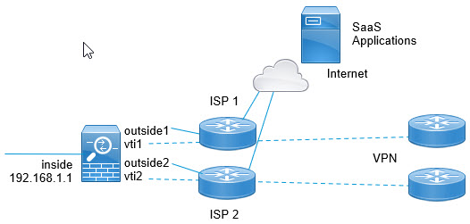
The following example shows how to set up direct Internet access for the following setup, where two outside interfaces connect to different Internet Service Providers, and virtual tunnel interfaces (VTI) host site-to-site VPN connections to the corporate network. The example shows how to direct traffic destined to select SaaS applications to the Internet and thus bypass the corporate network.


Direct Internet access example network.

Before you begin

This example assumes that you already have defined a site-to-site VPN using virtual tunnel interfaces (VTI) defined on the outside (WAN-facing) interfaces to connect the branch to the corporate hub and that it is functioning correctly. Traffic routed to the VTI interfaces is thus directed to the corporate network, whereas traffic routed directly to the outside interfaces goes to the Internet.

It also assumes that you have configured DNS servers and enabled DNS resolution on the device interfaces. Use the show dns trusted-source detail command to see which servers will be snooped. If you want to limit which servers are used, use the no dns trusted-source command to turn off snooping on select servers.

Procedure


Step 1

Configure network-service objects and groups to define the desired traffic.

The following example creates objects to define Office365 and WebEx, then creates a SaaS_Applications object group to contain these. You must create an object group, you cannot use objects directly in an access control entry.


object network-service office365
    domain outlook.office365.com tcp eq 443
    domain onlineapps.live.com tcp eq 443
    domain skype.live.com tcp eq 443
   
object network-service webex
    domain webex.com tcp eq 443
 
object-group network-service SaaS_Applications
    network-service-member office365
    network-service-member webex

Step 2

Create an extended ACL to match the desired traffic.

The following example matches traffic from the inside network to the SaaS Applications object group.


access-list DIA_traffic extended permit ip 192.168.1.0 255.255.255.0
object-group-network-service SaaS_Applications 

Step 3

(Optional.) Configure the cost on the egress interfaces.

Assuming the output1 and output2 interfaces are already configured and functioning, simply add the policy-route cost command. This step is optional if you want to configure the system to use round robin processing to load balance across the 2 egress WAN links. However, you must set the costs if you want to create an active/backup configuration, where one link is used unless it is down.

Following is an example of an equal cost active/active setup.


interface G0/0
  nameif outside1
  policy-route cost 1 

interface G0/1
  nameif outside2
  policy-route cost 1 

Following is an example where output1 is the preferred link, and output2 is used only if output1 is down.


interface G0/0
  nameif outside1
  policy-route cost 1 

interface G0/1
  nameif outside2
  policy-route cost 2 

Step 4

Create a route map to match the extended ACL and direct traffic accordingly.

The following example uses the ACL to match traffic, then uses adaptive interface cost to direct the traffic to the egress interface.


route-map mymap 10 
  match ip address DIA_traffic 
  set adaptive-interface cost outside1 outside2 

Step 5

Configure policy based routing on the ingress interface to send SaaS traffic to the outside interfaces.

The following example attaches the route map to the inside interface to enable policy-based routing for direct Internet access.


interface G1/0
  nameif inside
  policy-route route-map mymap 

Policy Based Routing in Action

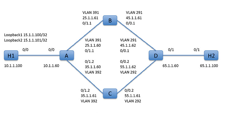
We will use this test setup to configure policy based routing with different match criteria and set actions to see how they are evaluated and applied.

First, we will start with the basic configuration for all the devices involved in the set-up. Here, A, B, C, and D represent ASA devices, and H1 and H2 represent IOS routers.

ASA-A:


ciscoasa(config)# interface GigabitEthernet0/0
ciscoasa(config-if)# nameif inside
ciscoasa(config-if)# security-level 100
ciscoasa(config-if)# ip address 10.1.1.60 255.255.255.0
ciscoasa(config)# interface GigabitEthernet0/1
ciscoasa(config-if)# no shut

ciscoasa(config)# interface GigabitEthernet0/1.1
ciscoasa(config-if)# vlan 391
ciscoasa(config-if)# nameif outside
ciscoasa(config-if)# security-level 0
ciscoasa(config-if)# ip address 25.1.1.60 255.255.255.0

ciscoasa(config)# interface GigabitEthernet0/1.2
ciscoasa(config-if)# vlan 392
ciscoasa(config-if)# nameif dmz
ciscoasa(config-if)# security-level 50
ciscoasa(config-if)# ip address 35.1.1.60 255.255.255.0

ASA-B:


ciscoasa(config)# interface GigabitEthernet0/0
ciscoasa(config-if)# no shut

ciscoasa(config)# interface GigabitEthernet0/0.1
ciscoasa(config-if)# vlan 291
ciscoasa(config-if)# nameif outside
ciscoasa(config-if)# security-level 0
ciscoasa(config-if)# ip address 45.1.1.61 255.255.255.0

ciscoasa(config)# interface GigabitEthernet0/1
ciscoasa(config-if)# no shut

ciscoasa(config)# interface GigabitEthernet0/1.1
ciscoasa(config-if)# vlan 391
ciscoasa(config-if)# nameif inside
ciscoasa(config-if)# security-level 100
ciscoasa(config-if)# ip address 25.1.1.61 255.255.255.0

ASA-C:


ciscoasa(config)# interface GigabitEthernet0/0
ciscoasa(config-if)# no shut

ciscoasa(config)# interface GigabitEthernet0/0.2
ciscoasa(config-if)# vlan 292
ciscoasa(config-if)# nameif outside
ciscoasa(config-if)# security-level 0
ciscoasa(config-if)# ip address 55.1.1.61 255.255.255.0

ciscoasa(config)# interface GigabitEthernet0/1
ciscoasa(config-if)# no shut

ciscoasa(config)# interface GigabitEthernet0/1.2
ciscoasa(config-if)# vlan 392
ciscoasa(config-if)# nameif inside
ciscoasa(config-if)# security-level 0
ciscoasa(config-if)# ip address 35.1.1.61 255.255.255.0

ASA-D:


ciscoasa(config)# interface GigabitEthernet0/0
ciscoasa(config-if)# no shut

ciscoasa(config) #interface GigabitEthernet0/0.1
ciscoasa(config-if)# vlan 291
ciscoasa(config-if)# nameif inside-1
ciscoasa(config-if)# security-level 100
ciscoasa(config-if)# ip address 45.1.1.62 255.255.255.0

ciscoasa(config)# interface GigabitEthernet0/0.2
ciscoasa(config-if)# vlan 292
ciscoasa(config-if)# nameif inside-2
ciscoasa(config-if)# security-level 100
ciscoasa(config-if)# ip address 55.1.1.62 255.255.255.0

ciscoasa(config)# interface GigabitEthernet0/1
ciscoasa(config-if)# nameif outside
ciscoasa(config-if)# security-level 0
ciscoasa(config-if)# ip address 65.1.1.60 255.255.255.0

H1:


ciscoasa(config)# interface Loopback1
ciscoasa(config-if)# ip address 15.1.1.100 255.255.255.255

ciscoasa(config-if)# interface Loopback2
ciscoasa(config-if)# ip address 15.1.1.101 255.255.255.255

ciscoasa(config)# ip route 0.0.0.0 0.0.0.0 10.1.1.60

H2:


ciscoasa(config)# interface GigabitEthernet0/1
ciscoasa(config-if)# ip address 65.1.1.100 255.255.255.0

ciscoasa(config-if)# ip route 15.1.1.0 255.255.255.0 65.1.1.60

We will configure PBR on ASA-A to route traffic sourced from H1.

ASA-A:


ciscoasa(config-if)# access-list pbracl_1 extended permit ip host 15.1.1.100 any

ciscoasa(config-if)# route-map testmap permit 10
ciscoasa(config-if)# match ip address pbracl_1
ciscoasa(config-if)# set ip next-hop 25.1.1.61

ciscoasa(config)# interface GigabitEthernet0/0
ciscoasa(config-if)# policy-route route-map testmap

ciscoasa(config-if)# debug policy-route

H1: ping 65.1.1.100 repeat 1 source loopback1


pbr: policy based route lookup called for 15.1.1.100/44397 to 65.1.1.100/0 proto 1 sub_proto 8 received on interface inside
pbr: First matching rule from ACL(2)
pbr: route map testmap, sequence 10, permit; proceed with policy routing
pbr: evaluating next-hop 25.1.1.61
pbr: policy based routing applied; egress_ifc = outside : next_hop = 25.1.1.61

The packet is forwarded as expected using the next-hop address in the route-map.

When a next-hop is configured, we do a lookup in input route table to identify a connected route to the configured next-hop and use the corresponding interface. The input route table for this example is shown here (with the matching route entry highlighted).


in   255.255.255.255 255.255.255.255 identity
in   10.1.1.60       255.255.255.255 identity
in   25.1.1.60       255.255.255.255 identity
in   35.1.1.60       255.255.255.255 identity
in   10.127.46.17    255.255.255.255 identity
in   10.1.1.0        255.255.255.0   inside
in   25.1.1.0        255.255.255.0   outside
in   35.1.1.0        255.255.255.0   dmz

Next let's configure ASA-A to route packets from H1 loopback2 out of ASA-A dmz interface.


ciscoasa(config)# access-list pbracl_2 extended permit ip host 15.1.1.101 any

ciscoasa(config)# route-map testmap permit 20
ciscoasa(config-route-map)# match ip address pbracl
ciscoasa(config-route-map)# set ip next-hop 35.1.1.61

ciscoasa(config)# show run route-map
!
route-map testmap permit 10
  match ip address pbracl_1
  set ip next-hop 25.1.1.61
!
route-map testmap permit 20
  match ip address pbracl_2
  set ip next-hop 35.1.1.61
!

H1: ping 65.1.1.100 repeat 1 source loopback2

The debugs are shown here:


pbr: policy based route lookup called for 15.1.1.101/1234 to 65.1.1.100/1234 proto 6 sub_proto 0 received on interface inside
pbr: First matching rule from ACL(3)
pbr: route map testmap, sequence 20, permit; proceed with policy routing
pbr: evaluating next-hop 35.1.1.61
pbr: policy based routing applied; egress_ifc = dmz : next_hop = 35.1.1.61

and the route entry chosen from input route table is shown here:


in   255.255.255.255 255.255.255.255 identity
 in   10.1.1.60       255.255.255.255 identity
 in   25.1.1.60       255.255.255.255 identity
 in   35.1.1.60       255.255.255.255 identity
 in   10.127.46.17    255.255.255.255 identity
 in   10.1.1.0        255.255.255.0   inside
 in   25.1.1.0        255.255.255.0   outside
 in   35.1.1.0        255.255.255.0   dmz

History for Policy Based Routing

Table 1. History for Route Maps

Feature Name

Platform Releases

Feature Information

Path monitoring through HTTP client

9.20(1)

PBR can now use the performance metrics (RTT, jitter, packet-lost, and MOS) collected by path monitoring through HTTP client on the application domain rather than the metrics on a specific destination IP. HTTP based path-monitoring can be configured on the interface using Network Service Group objects.

Path monitoring metrics in PBR.

9.18(1)

PBR uses the metrics to determine the best path (egress interface) for forwarding the traffic. Path monitoring periodically notifies PBR with the monitored interface whose metric got changed. PBR retrieves the latest metric values for the monitored interfaces from the path monitoring database and updates the data path.

New/Modified commands: clear path-monitoring , policy-route , show path-monitoring

Policy based routing

9.4(1)

Policy Based Routing (PBR) is a mechanism by which traffic is routed through specific paths with a specified QoS using ACLs. ACLs let traffic be classified based on the content of the packet’s Layer 3 and Layer 4 headers. This solution lets administrators provide QoS to differentiated traffic, distribute interactive and batch traffic among low-bandwidth, low-cost permanent paths and high-bandwidth, high-cost switched paths, and allows Internet service providers and other organizations to route traffic originating from various sets of users through well-defined Internet connections.

We introduced the following commands: set ip next-hop verify-availability, set ip next-hop, set ip next-hop recursive, set interface, set ip default next-hop, set default interface, set ip df, set ip dscp, policy-route route-map, show policy-route, debug policy-route

IPv6 support for Policy Based Routing

9.5(1)

IPv6 addresses are now supported for Policy Based Routing.

We introduced the following commands: set ipv6 next-hop,set default ipv6-next hop, set ipv6 dscp

VXLAN support for Policy Based Routing

9.5(1)

You can now enable Policy Based Routing on a VNI interface.

We did not modify any commands.

Policy Based Routing support for Identity Firewall and Cisco Trustsec

9.5(1)

You can configure Identity Firewall and Cisco TrustSec and then use Identity Firewall and Cisco TrustSec ACLs in Policy Based Routing route maps.

We did not modify any commands.