Getting Started

This chapter describes how to get started with your ASA.

Access the Console for the Command-Line Interface

In some cases, you may need to use the CLI to configure basic settings for ASDM access.

For initial configuration, access the CLI directly from the console port. Later, you can configure remote access using Telnet or SSH according to Management Access. If your system is already in multiple context mode, then accessing the console port places you in the system execution space.


Note


For ASA virtual console access, see the ASA virtual quick start guide.


Access the ISA 3000 Console

Follow these steps to access the appliance console.

Procedure


Step 1

Connect a computer to the console port using the provided console cable, and connect to the console using a terminal emulator set for 9600 baud, 8 data bits, no parity, 1 stop bit, no flow control.

See the hardware guide for your ASA for more information about the console cable.

Step 2

Press the Enter key to see the following prompt:


ciscoasa>

This prompt indicates that you are in user EXEC mode. Only basic commands are available from user EXEC mode.

Step 3

Access privileged EXEC mode.

enable

You are prompted to change the password the first time you enter the enable command:

Example:


ciscoasa> enable
Password:
The enable password is not set. Please set it now.
Enter Password: ******
Repeat Password: ******
ciscoasa#

All non-configuration commands are available in privileged EXEC mode. You can also enter configuration mode from privileged EXEC mode.

To exit privileged mode, enter the disable, exit, or quit command.

Step 4

Access global configuration mode.

configure terminal

Example:


ciscoasa# configure terminal
ciscoasa(config)#

You can begin to configure the ASA from global configuration mode. To exit global configuration mode, enter the exit, quit, or end command.


Access the Firepower 1000, and Secure Firewall 1200/3100/4200 Console

The Firepower 1000, and Secure Firewall 1200/3100/4200 console port connects you to the ASA CLI. From the ASA CLI, you can then connect to the FXOS CLI using Telnet for troubleshooting purposes.

Procedure


Step 1

Connect your management computer to the console port. Be sure to install any necessary serial drivers for your operating system. Use the following serial settings:

  • 9600 baud

  • 8 data bits

  • No parity

  • 1 stop bit

You connect to the ASA CLI. There are no user credentials required for console access by default.

Step 2

Access privileged EXEC mode.

enable

You are prompted to change the password the first time you enter the enable command.

Example:


ciscoasa> enable
Password:
The enable password is not set. Please set it now.
Enter Password: ******
Repeat Password: ******
ciscoasa#

The enable password that you set on the ASA is also the FXOS admin user password if the ASA fails to boot up, and you enter FXOS failsafe mode.

All non-configuration commands are available in privileged EXEC mode. You can also enter configuration mode from privileged EXEC mode.

To exit privileged EXEC mode, enter the disable , exit , or quit command.

Step 3

Access global configuration mode.

configure terminal

Example:


ciscoasa# configure terminal
ciscoasa(config)#

You can begin to configure the ASA from global configuration mode. To exit global configuration mode, enter the exit , quit , or end command.

Step 4

(Optional) Connect to the FXOS CLI.

connect fxos [admin]

  • admin —Provides admin-level access. Without this option, users have read-only access. Note that no configuration commands are available even in admin mode.

You are not prompted for user credentials. The current ASA username is passed through to FXOS, and no additional login is required. To return to the ASA CLI, enter exit or type Ctrl-Shift-6, x.

Within FXOS, you can view user activity using the scope security/show audit-logs command.

Example:


ciscoasa# connect fxos admin
Connecting to fxos.
Connected to fxos. Escape character sequence is 'CTRL-^X'.
firepower# 
firepower# exit
Connection with FXOS terminated.
Type help or '?' for a list of available commands.
ciscoasa#


Access the ASA Console on the Firepower 4100/9300 Chassis

For initial configuration, access the command-line interface by connecting to the Firepower 4100/9300 chassis supervisor (either to the console port or remotely using Telnet or SSH) and then connecting to the ASA security module.

Procedure


Step 1

Connect to the Firepower 4100/9300 chassis supervisor CLI (console or SSH), and then session to the ASA:

connect module slot { console | telnet}

The benefits of using a Telnet connection is that you can have multiple sessions to the module at the same time, and the connection speed is faster.

The first time you access the module, you access the FXOS module CLI. You must then connect to the ASA application.

connect asa

Example:


Firepower# connect module 1 console
Firepower-module1> connect asa

asa>

Step 2

Access privileged EXEC mode, which is the highest privilege level.

enable

You are prompted to change the password the first time you enter the enable command.

Example:


asa> enable
Password:
The enable password is not set. Please set it now.
Enter Password: ******
Repeat Password: ******
asa#

All non-configuration commands are available in privileged EXEC mode. You can also enter configuration mode from privileged EXEC mode.

To exit privileged mode, enter the disable, exit, or quit command.

Step 3

Enter global configuration mode.

configure terminal

Example:


asa# configure terminal
asa(config)# 

To exit global configuration mode, enter the disable , exit , or quit command.

Step 4

Exit the application console to the FXOS module CLI by entering Ctrl-a, d

You might want to use the FXOS module CLI for troubleshooting purposes.

Step 5

Return to the supervisor level of the FXOS CLI.

Exit the console:

  1. Enter ~

    You exit to the Telnet application.

  2. To exit the Telnet application, enter:

    telnet>quit

Exit the Telnet session:

  1. Enter Ctrl-], .


Configure ASDM Access

This section describes how to access ASDM with a default configuration and how to configure access if you do not have a default configuration.

Use the Factory Default Configuration for ASDM Access

With a factory default configuration, ASDM connectivity is pre-configured with default network settings.

Procedure


Connect to ASDM using the following interface and network settings:

  • The management interface depends on your model:

    • Firepower 1010, Secure Firewall 1210/1220—Management 1/1 (192.168.45.1), or inside Ethernet 1/2 through 1/8(1010 and 1210) or 1/10 (1220) (192.168.1.1). Management hosts are limited to the 192.168.45.0/24 network, and inside hosts are limited to the 192.168.1.0/24 network.

    • Firepower 1100, Secure Firewall 3100, 4200—Inside Ethernet 1/2 (192.168.1.1), or Management 1/1 (from DHCP). Inside hosts are limited to the 192.168.1.0/24 network. Management hosts are allowed from any network.

    • Firepower 4100/9300—The Management type interface and IP address of your choice defined when you deployed. Management hosts are allowed from any network.

    • ASA Virtual—Management 0/0 (set during deployment). Management hosts are limited to the management network.

    • ISA 3000—Management 1/1 (192.168.1.1). Management hosts are limited to the 192.168.1.0/24 network.

Note


If you change to multiple context mode, you can access ASDM from the admin context using the network settings above.


Customize ASDM Access

Use this procedure if one or more of the following conditions applies:

  • You do not have a factory default configuration

  • You want to change to transparent firewall mode

  • You want to change to multiple context mode

For routed, single mode, for quick and easy ASDM access, we recommend applying the factory default configuration with the option to set your own management IP address. Use the procedure in this section only if you have special needs such as setting transparent or multiple context mode, or if you have other configuration that you need to preserve.


Note


For the ASAv, you can configure transparent mode when you deploy, so this procedure is primarily useful after you deploy if you need to clear your configuration, for example.


Procedure


Step 1

Access the CLI at the console port.

Step 2

(Optional) Enable transparent firewall mode:

This command clears your configuration.

firewall transparent

Step 3

Configure the management interface:


interface interface_id    
   nameif name 
   security-level level    
   no shutdown    
   ip address ip_address mask

Example:


ciscoasa(config)# interface management 0/0
ciscoasa(config-if)# nameif management
ciscoasa(config-if)# security-level 100
ciscoasa(config-if)# no shutdown
ciscoasa(config-if)# ip address 192.168.1.1 255.255.255.0

The security-level is a number between 1 and 100, where 100 is the most secure.

Step 4

(For directly-connected management hosts) Set the DHCP pool for the management network:


dhcpd address ip_address-ip_address interface_name
dhcpd enable interface_name

Example:


ciscoasa(config)# dhcpd address 192.168.1.2-192.168.1.254 management
ciscoasa(config)# dhcpd enable management

Make sure you do not include the interface address in the range.

Step 5

(For remote management hosts) Configure a route to the management hosts:

route management_ifc management_host_ip mask gateway_ip 1

Example:


ciscoasa(config)# route management 10.1.1.0 255.255.255.0 192.168.1.50 1

Step 6

Enable the HTTP server for ASDM:

http server enable

Step 7

Allow the management host(s) to access ASDM:

http ip_address mask interface_name

Example:


ciscoasa(config)# http 192.168.1.0 255.255.255.0 management

Step 8

Save the configuration:

write memory

Step 9

(Optional) Set the mode to multiple mode:

mode multiple

When prompted, confirm that you want to convert the existing configuration to be the admin context. You are then prompted to reload the ASA.


Examples

The following configuration converts the firewall mode to transparent mode, configures the Management 0/0 interface, and enables ASDM for a management host:


firewall transparent
interface management 0/0

ip address 192.168.1.1 255.255.255.0
nameif management
security-level 100
no shutdown

dhcpd address 192.168.1.2-192.168.1.254 management
dhcpd enable management
http server enable
http 192.168.1.0 255.255.255.0 management

Start ASDM

Launch ASDM using the ASDM-IDM Launcher. The Launcher is an application downloaded from the ASA using a web browser that you can use to connect to any ASA IP address. You do not need to re-download the launcher if you want to connect to other ASAs.

Within ASDM, you can choose a different ASA IP address to manage.

This section describes how to connect to ASDM initially, and then launch ASDM using the Launcher.

ASDM stores files in the local \Users\<user_id>\.asdm directory, including cache, log, and preferences, and also in the Temp directory, including Secure Client profiles.

Procedure


Step 1

On the computer that you specified as the ASDM client, enter the following URL:

https://asa_ip_address/admin

Note


Be sure to specify https://, and not http:// or just the IP address (which defaults to HTTP); the ASA does not automatically forward an HTTP request to HTTPS.

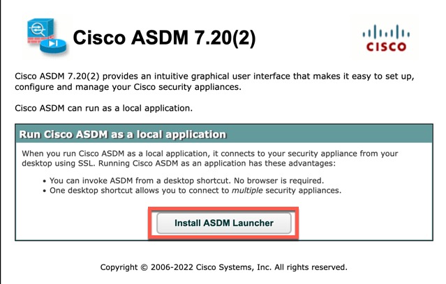
The ASDM launch page appears with the following button:

Install ASDM Launcher

Step 2

To download the Launcher and start ASDM:

  1. Click Install ASDM Launcher.

    Figure 1. Install ASDM Launcher
    Install ASDM Launcher
  2. Leave the username and password fields empty (for a new installation), and click OK.

    With no HTTPS authentication configured, you can gain access to ASDM with no username and the enable password, which is blank by default. When you enter the enable command at the CLI for the first time, you are prompted to change the password; this behavior is not enforced when you log into ASDM. We suggest that you change the enable password as soon as possible so that it does not remain blank; see Set the Hostname, Domain Name, and the Enable and Telnet Passwords. Note: If you enabled HTTPS authentication, enter your username and associated password. Even without authentication, if you enter a username and password at the login screen (instead of leaving the username blank), ASDM checks the local database for a match.

  3. Save the installer to your computer, and then start the installer. The ASDM-IDM Launcher opens automatically after installation is complete.

  4. Enter the management IP address, the same username and password (blank for a new installation), and then click OK.


Customize ASDM Operation

You can install an identity certificate to successfully launch ASDM as well as increase the ASDM heap memory so it can handle larger configurations.

Install an Identity Certificate for ASDM

When using Java 7 update 51 and later, the ASDM Launcher requires a trusted certificate. An easy approach to fulfill the certificate requirements is to install a self-signed identity certificate. You can use Java Web Start to launch ASDM until you install a certificate.

See the following document to install a self-signed identity certificate on the ASA for use with ASDM, and to register the certificate with Java.

http://www.cisco.com/go/asdm-certificate

Increase the ASDM Configuration Memory

ASDM supports a maximum configuration size of 512 KB. If you exceed this amount you may experience performance issues. For example, when you load the configuration, the status dialog box shows the percentage of the configuration that is complete, yet with large configurations it stops incrementing and appears to suspend operation, even though ASDM might still be processing the configuration. If this situation occurs, we recommend that you consider increasing the ASDM system heap memory. To confirm that you are experiencing memory exhaustion, monitor the Java console for the "java.lang.OutOfMemoryError" message.

Increase the ASDM Configuration Memory in Windows

To increase the ASDM heap memory size, edit the run.bat file by performing the following procedure.

Procedure

Step 1

Go to the ASDM installation directory, for example C:\Program Files (x86)\Cisco Systems\ASDM.

Step 2

Edit the run.bat file with any text editor.

Step 3

In the line that starts with “start javaw.exe”, change the argument prefixed with “-Xmx” to specify your desired heap size. For example, change it to -Xmx768M for 768 MB or -Xmx1G for 1 GB.

Step 4

Save the run.bat file.


Increase the ASDM Configuration Memory in Mac OS

To increase the ASDM heap memory size, edit the Info.plist file by performing the following procedure.

Procedure

Step 1

Right-click the Cisco ASDM-IDM icon, and choose Show Package Contents.

Step 2

In the Contents folder, double-click the Info.plist file. If you have Developer tools installed, it opens in the Property List Editor. Otherwise, it opens in TextEdit.

Step 3

Under Java > VMOptions, change the string prefixed with “-Xmx” to specify your desired heap size. For example, change it to -Xmx768M for 768 MB or -Xmx1G for 1 GB.

Step 4

If this file is locked, you see an error such as the following:

Step 5

Click Unlock and save the file.

If you do not see the Unlock dialog box, exit the editor, right-click the Cisco ASDM-IDM icon, choose Copy Cisco ASDM-IDM, and paste it to a location where you have write permissions, such as the Desktop. Then change the heap size from this copy.


Factory Default Configurations

The factory default configuration is the configuration applied by Cisco to new ASAs.

  • Firepower 1010—The factory default configuration enables a functional inside/outside configuration. You can manage the ASA using ASDM from either the management interface or the inside switch ports.

  • Firepower 1100—The factory default configuration enables a functional inside/outside configuration. You can manage the ASA using ASDM from either the management interface or the inside interface.

  • Secure Firewall 1210/1220—The factory default configuration enables a functional inside/outside configuration. You can manage the ASA using ASDM from either the management interface or the inside switch ports.

  • Secure Firewall 3100—The factory default configuration enables a functional inside/outside configuration. You can manage the ASA using ASDM from either the Management 1/1 interface or the inside interface.

  • Secure Firewall 4200—The factory default configuration enables a functional inside/outside configuration. You can manage the ASA using ASDM from either the Management 1/1 interface or the inside interface.

  • Firepower 4100/9300 chassis—When you deploy the standalone or cluster of ASAs, the factory default configuration configures an interface for management so that you can connect to it using ASDM, with which you can then complete your configuration.

  • ASA Virtual—Depending on your hypervisor, as part of deployment, the deployment configuration (the initial virtual deployment settings) configures an interface for management so that you can connect to it using ASDM, with which you can then complete your configuration. You can also configure failover IP addresses. You can also apply a “factory default” configuration if desired.

  • ISA 3000—The factory default configuration is an almost-complete transparent firewall mode configuration with all inside and outside interfaces on the same network; you can connect to the management interface with ASDM to set the IP address of your network. Hardware bypass is enabled for two interface pairs.

For appliances, the factory default configuration is available only for routed firewall mode and single context mode, except for the ISA 3000, where the factory default configuration is only available in transparent mode. For the ASA virtual and the Firepower 4100/9300 chassis, you can choose transparent or routed mode at deployment.


Note


In addition to the image files and the (hidden) default configuration, the following folders and files are standard in flash memory: log/, crypto_archive/, and coredumpinfo/coredump.cfg. The date on these files may not match the date of the image files in flash memory. These files aid in potential troubleshooting; they do not indicate that a failure has occurred.


Restore the Factory Default Configuration

This section describes how to restore the factory default configuration. Both CLI and ASDM procedures are provided. For the ASA virtual, this procedure erases the deployment configuration and applies the following configuration:


interface management 0/0
  ip address 192.168.1.1 255.255.255.0
  nameif management
  security-level 100
  no shutdown
!
asdm logging informational
asdm history enable
!
http server enable
http 192.168.1.0 255.255.255.0 management
!
dhcpd address 192.168.1.2-192.168.1.254 management
dhcpd enable management


Note


On the Firepower 4100/9300, restoring the factory default configuration simply erases the configuration; to restore the default configuration, you must re-deploy the ASA from the supervisor.


Before you begin

This feature is available only in routed firewall mode, except for the ISA 3000, where this command is only supported in transparent mode. In addition, this feature is available only in single context mode; an ASA with a cleared configuration does not have any defined contexts to configure automatically using this feature.

Procedure


Step 1

Restore the factory default configuration:

configure factory-default [ip_address [mask]]

Example:


ciscoasa(config)# configure factory-default 10.1.1.1 255.255.255.0

If you specify the ip_address , then you set the inside or management interface IP address, depending on your model, instead of using the default IP address. See the following model guidelines for which interface is set by the ip_address option:

  • Firepower 1010—Sets the management interface IP address.

  • Firepower 1100—Sets the inside interface IP address.

  • Secure Firewall 1210/1220—Sets the management interface IP address.

  • Secure Firewall 3100—Sets the inside interface IP address.

  • Secure Firewall 4200—Sets the inside interface IP address.

  • Firepower 4100/9300—No effect.

  • ASA Virtual—Sets the management interface IP address.

  • ISA 3000—Sets the management interface IP address.

The http command uses the subnet you specify. Similarly, the dhcpd address command range consists of all available addresses higher than the IP address you specify. For example, if you specify 10.5.6.78 with a subnet mask of 255.255.255.0, then the DHCP address range will be 10.5.6.79-10.5.6.254.

For the Firepower 1000, and the Secure Firewall 1200, 3100, 4200: This command clears the boot system command, if present, along with the rest of the configuration. This configuration change does not affect the image at bootup: the currently-loaded image continues to be used.

For all other models: This command clears the boot system command, if present, along with the rest of the configuration. The boot system command lets you boot from a specific image. The next time you reload the ASA after restoring the factory configuration, it boots from the first image in internal flash memory; if you do not have an image in internal flash memory, the ASA does not boot.

Example:


docs-bxb-asa3(config)# configure factory-default 10.86.203.151 255.255.254.0
Based on the management IP address and mask, the DHCP address
pool size is reduced to 103 from the platform limit 256

WARNING: The boot system configuration will be cleared.
The first image found in disk0:/ will be used to boot the
system on the next reload.
Verify there is a valid image on disk0:/ or the system will
not boot.

Begin to apply factory-default configuration:
Clear all configuration
WARNING: The new maximum-session limit will take effect after the running-config is saved and the system boots next time. Command accepted
WARNING: Local user database is empty and there are still 'aaa' commands for 'LOCAL'.
Executing command: interface management0/0
Executing command: nameif management
INFO: Security level for "management" set to 0 by default.
Executing command: ip address 10.86.203.151 255.255.254.0
Executing command: security-level 100
Executing command: no shutdown
Executing command: exit
Executing command: http server enable
Executing command: http 10.86.202.0 255.255.254.0 management
Executing command: dhcpd address 10.86.203.152-10.86.203.254 management
Executing command: dhcpd enable management
Executing command: logging asdm informational
Factory-default configuration is completed
ciscoasa(config)#                                     

Step 2

Save the default configuration to flash memory:

write memory

This command saves the running configuration to the default location for the startup configuration, even if you previously configured the boot config command to set a different location; when the configuration was cleared, this path was also cleared.

Step 3

(ASDM procedure.) In the main ASDM application window, do the following:

  1. Choose File > Reset Device to the Factory Default Configuration.

    The Reset Device to the Default Configuration dialog box appears.

  2. (Optional) Enter the Management IP address of the management or inside interface, instead of using the default address.

    See the previous CLI step for details about which interface IP is set per model.

  3. (Optional) Choose the Management Subnet Mask from the drop-down list.

  4. Click OK.

    A confirmation dialog box appears.

    Note


    For the Firepower 1000, and the Secure Firewall 1200, 3100, 4200: This command clears the location of the boot image, if present, along with the rest of the configuration. This configuration change does not affect the image at bootup: the currently-loaded image continues to be used.

    For all other models: This action also clears the location of the boot image, if present, along with the rest of the configuration. The Configuration > Device Management > System Image/Configuration > Boot Image/Configuration pane lets you boot from a specific image, including an image on the external memory. The next time you reload the ASA after restoring the factory configuration, it boots from the first image in internal flash memory; if you do not have an image in internal flash memory, the ASA does not boot.

  5. Click Yes.

  6. After you restore the default configuration, save this configuration to internal flash memory. Choose File > Save Running Configuration to Flash.

    Choosing this option saves the running configuration to the default location for the startup configuration, even if you have previously configured a different location. When the configuration was cleared, this path was also cleared.


Restore the ASA Virtual Deployment Configuration

This section describes how to restore the ASA virtual deployment (Day 0) configuration.

Procedure


Step 1

For failover, power off the standby unit.

To prevent the standby unit from becoming active, you must power it off. If you leave it on, when you erase the active unit configuration, then the standby unit becomes active. When the former active unit reloads and reconnects over the failover link, the old configuration will sync from the new active unit, wiping out the deployment configuration you wanted.

Step 2

Restore the deployment configuration after you reload. For failover, enter this command on the active unit:

write erase

Note


The ASA virtual boots the current running image, so you are not reverted to the original boot image. To use the original boot image, see the boot image command.

Do not save the configuration.

Step 3

Reload the ASA virtual and load the deployment configuration:

reload

Step 4

For failover, power on the standby unit.

After the active unit reloads, power on the standby unit. The deployment configuration will sync to the standby unit.


Firepower 1010 Default Configuration

The default factory configuration for the Firepower 1010 configures the following:

  • Hardware switch—Ethernet 1/2 through 1/8 belong to VLAN 1

  • inside→outside traffic flow—Ethernet 1/1 (outside), VLAN1 (inside)

  • management—Management 1/1 (management), IP address 192.168.45.1

  • outside IP address from DHCP, inside IP address—192.168.1.1

  • DHCP server on inside interface, management interface

  • Default route from outside DHCP

  • ASDM access—Management and inside hosts allowed. Management hosts are limited to the 192.168.45.0/24 network, and inside hosts are limited to the 192.168.1.0/24 network.

  • NAT—Interface PAT for all traffic from inside to outside.

  • DNS servers—OpenDNS servers are pre-configured.

The configuration consists of the following commands:


interface Vlan1
nameif inside
security-level 100
ip address 192.168.1.1 255.255.255.0
no shutdown
!
interface Management1/1
managment-only
nameif management
no shutdown
security-level 100
ip address 192.168.45.1 255.255.255.0
!
interface Ethernet1/1
nameif outside
ip address dhcp setroute
no shutdown
!
interface Ethernet1/2
no shutdown
switchport
switchport mode access
switchport access vlan 1
!
interface Ethernet1/3
no shutdown
switchport
switchport mode access
switchport access vlan 1
!
interface Ethernet1/4
no shutdown
switchport
switchport mode access
switchport access vlan 1
!
interface Ethernet1/5
no shutdown
switchport
switchport mode access
switchport access vlan 1
!
interface Ethernet1/6
no shutdown
switchport
switchport mode access
switchport access vlan 1
!
interface Ethernet1/7
no shutdown
switchport
switchport mode access
switchport access vlan 1
!
interface Ethernet1/8
no shutdown
switchport
switchport mode access
switchport access vlan 1
!
object network obj_any
   subnet 0.0.0.0 0.0.0.0
   nat (any,outside) dynamic interface
!
dhcpd auto_config outside
dhcpd address 192.168.1.20-192.168.1.254 inside
dhcpd address 192.168.45.10-192.168.45.12 management
dhcpd enable inside
dhcpd enable management
!
http server enable
http 192.168.45.0 255.255.255.0 management
http 192.168.1.0 255.255.255.0 inside
!
dns domain-lookup outside
dns server-group DefaultDNS
   name-server 208.67.222.222 outside
   name-server 208.67.220.220 outside
!

Firepower 1100 Default Configuration

The default factory configuration for the Firepower 1100 configures the following:

  • inside→outside traffic flow—Ethernet 1/1 (outside), Ethernet 1/2 (inside)

  • outside IP address from DHCP, inside IP address—192.168.1.1

  • management—Management 1/1 (management), IP address from DHCP

  • DHCP server on inside interface

  • Default routes from outside DHCP, management DHCP

  • ASDM access—Management and inside hosts allowed. Inside hosts are limited to the 192.168.1.0/24 network.

  • NAT—Interface PAT for all traffic from inside to outside.

  • DNS servers—OpenDNS servers are pre-configured.

The configuration consists of the following commands:


interface Management1/1
  management-only
  nameif management
  security-level 100
  ip address dhcp setroute
  no shutdown
!
interface Ethernet1/1
  nameif outside
  security-level 0
  ip address dhcp setroute
  no shutdown
!
interface Ethernet1/2
  nameif inside
  security-level 100
  ip address 192.168.1.1 255.255.255.0
  no shutdown
!
object network obj_any
  subnet 0.0.0.0 0.0.0.0
  nat (any,outside) dynamic interface
!
http server enable
http 0.0.0.0 0.0.0.0 management
http 192.168.1.0 255.255.255.0 inside
!
dhcpd auto_config outside
dhcpd address 192.168.1.20-192.168.1.254 inside
dhcpd enable inside
!
dns domain-lookup outside
dns server-group DefaultDNS
   name-server 208.67.222.222 outside
   name-server 208.67.220.220 outside
!

Secure Firewall 1210/1220 Default Configuration

The default factory configuration for the Secure Firewall 1210/1220 configures the following:

  • Hardware switch—Ethernet 1/2 through 1/8 (1210) or Ethernet 1/2 through 1/10 (1220) belong to VLAN 1

  • inside→outside traffic flow—Ethernet 1/1 (outside), VLAN1 (inside)

  • management—Management 1/1 (management), IP address 192.168.45.1

  • outside IP address from DHCP, inside IP address—192.168.1.1

  • DHCP server on inside interface, management interface

  • Default route from outside DHCP

  • ASDM access—Management and inside hosts allowed. Management hosts are limited to the 192.168.45.0/24 network, and inside hosts are limited to the 192.168.1.0/24 network.

  • NAT—Interface PAT for all traffic from inside to outside.

  • DNS servers—OpenDNS servers are pre-configured.

The configuration consists of the following commands:


interface Vlan1
nameif inside
security-level 100
ip address 192.168.1.1 255.255.255.0
no shutdown
!
interface Management1/1
managment-only
nameif management
no shutdown
security-level 100
ip address 192.168.45.1 255.255.255.0
!
interface Ethernet1/1
nameif outside
ip address dhcp setroute
no shutdown
!
interface Ethernet1/2
no shutdown
switchport
switchport mode access
switchport access vlan 1
!
interface Ethernet1/3
no shutdown
switchport
switchport mode access
switchport access vlan 1
!
interface Ethernet1/4
no shutdown
switchport
switchport mode access
switchport access vlan 1
!
interface Ethernet1/5
no shutdown
switchport
switchport mode access
switchport access vlan 1
!
interface Ethernet1/6
no shutdown
switchport
switchport mode access
switchport access vlan 1
!
interface Ethernet1/7
no shutdown
switchport
switchport mode access
switchport access vlan 1
!
interface Ethernet1/8
no shutdown
switchport
switchport mode access
switchport access vlan 1
!
! 1220
interface Ethernet1/9
no shutdown
switchport
switchport mode access
switchport access vlan 1
!
! 1220
interface Ethernet1/10
no shutdown
switchport
switchport mode access
switchport access vlan 1
!
object network obj_any
   subnet 0.0.0.0 0.0.0.0
   nat (any,outside) dynamic interface
!
dhcpd auto_config outside
dhcpd address 192.168.1.20-192.168.1.254 inside
dhcpd address 192.168.45.10-192.168.45.12 management
dhcpd enable inside
dhcpd enable management
!
http server enable
http 192.168.45.0 255.255.255.0 management
http 192.168.1.0 255.255.255.0 inside
!
dns domain-lookup outside
dns server-group DefaultDNS
   name-server 208.67.222.222 outside
   name-server 208.67.220.220 outside
!

Secure Firewall 3100 Default Configuration

The default factory configuration for the Secure Firewall 3100 configures the following:

  • inside→outside traffic flow—Ethernet 1/1 (outside), Ethernet 1/2 (inside)

  • outside IP address from DHCP, inside IP address—192.168.1.1

  • management—Management 1/1 (management), IP address from DHCP

  • DHCP server on inside interface

  • Default routes from outside DHCP, management DHCP

  • ASDM access—Management and inside hosts allowed. Inside hosts are limited to the 192.168.1.0/24 network.

  • NAT—Interface PAT for all traffic from inside to outside.

  • DNS servers—OpenDNS servers are pre-configured.

The configuration consists of the following commands:


interface Management1/1
  management-only
  nameif management
  security-level 100
  ip address dhcp setroute
  no shutdown
!
interface Ethernet1/1
  nameif outside
  security-level 0
  ip address dhcp setroute
  no shutdown
!
interface Ethernet1/2
  nameif inside
  security-level 100
  ip address 192.168.1.1 255.255.255.0
  no shutdown
!
object network obj_any
  subnet 0.0.0.0 0.0.0.0
  nat (any,outside) dynamic interface
!
http server enable
http 0.0.0.0 0.0.0.0 management
http 192.168.1.0 255.255.255.0 inside
!
dhcpd auto_config outside
dhcpd address 192.168.1.20-192.168.1.254 inside
dhcpd enable inside
!
dns domain-lookup outside
dns server-group DefaultDNS
   name-server 208.67.222.222 outside
   name-server 208.67.220.220 outside
!

Secure Firewall 4200 Default Configuration

The default factory configuration for the Secure Firewall 4200 configures the following:

  • inside→outside traffic flow—Ethernet 1/1 (outside), Ethernet 1/2 (inside)

  • outside IP address from DHCP, inside IP address—192.168.1.1

  • management—Management 1/1 (management), IP address from DHCP

  • DHCP server on inside interface

  • Default routes from outside DHCP, management DHCP

  • ASDM access—Management and inside hosts allowed. Inside hosts are limited to the 192.168.1.0/24 network.

  • NAT—Interface PAT for all traffic from inside to outside.

  • DNS servers—OpenDNS servers are pre-configured.

The configuration consists of the following commands:


interface Management1/1
  management-only
  nameif management
  security-level 100
  ip address dhcp setroute
  no shutdown
!
interface Ethernet1/1
  nameif outside
  security-level 0
  ip address dhcp setroute
  no shutdown
!
interface Ethernet1/2
  nameif inside
  security-level 100
  ip address 192.168.1.1 255.255.255.0
  no shutdown
!
object network obj_any
  subnet 0.0.0.0 0.0.0.0
  nat (any,outside) dynamic interface
!
http server enable
http 0.0.0.0 0.0.0.0 management
http 192.168.1.0 255.255.255.0 inside
!
dhcpd auto_config outside
dhcpd address 192.168.1.20-192.168.1.254 inside
dhcpd enable inside
!
dns domain-lookup outside
dns server-group DefaultDNS
   name-server 208.67.222.222 outside
   name-server 208.67.220.220 outside
!

Firepower 4100/9300 Chassis Default Configuration

When you deploy the ASA on the Firepower 4100/9300 chassis, you can pre-set many parameters that let you connect to the Management interface using ASDM. A typical configuration includes the following settings:

  • Management interface:

    • Management type interface of your choice defined on the Firepower 4100/9300 Chassis supervisor

    • Named “management”

    • IP address of your choice

    • Security level 0

    • Management-only

  • Default route through the management interface

  • ASDM access—All hosts allowed.

The configuration for a standalone unit consists of the following commands. For additional configuration for clustered units, see Create an ASA Cluster.


interface <management_ifc>
  management-only
  ip address <ip_address> <mask>
  ipv6 address <ipv6_address>
  ipv6 enable
  nameif management
  security-level 0
  no shutdown
!
http server enable
http 0.0.0.0 0.0.0.0 management
http ::/0 management
!
route management 0.0.0.0 0.0.0.0 <gateway_ip> 1
ipv6 route management ::/0 <gateway_ipv6>

ISA 3000 Default Configuration

The default factory configuration for the ISA 3000 configures the following:

  • Transparent firewall mode—A transparent firewall is a Layer 2 firewall that acts like a “bump in the wire,” or a “stealth firewall,” and is not seen as a router hop to connected devices.

  • 1 Bridge Virtual Interface—All member interfaces are in the same network (IP address not pre-configured; you must set to match your network): GigabitEthernet 1/1 (outside1), GigabitEthernet 1/2 (inside1), GigabitEthernet 1/3 (outside2), GigabitEthernet 1/4 (inside2)

  • All inside and outside interfaces can communicate with each other.

  • Management 1/1 interface—192.168.1.1/24 for ASDM access.

  • DHCP for clients on management.

  • ASDM access—Management hosts allowed.

  • Hardware bypass is enabled for the following interface pairs: GigabitEthernet 1/1 & 1/2; GigabitEthernet 1/3 & 1/4


    Note


    When the ISA 3000 loses power and goes into hardware bypass mode, only the above interface pairs can communicate; inside1 and inside2, and outside1 and outside2 can no longer communicate. Any existing connections between these interfaces will be lost. When the power comes back on, there is a brief connection interruption as the ASA takes over the flows.


The configuration consists of the following commands:


firewall transparent

interface GigabitEthernet1/1
 	bridge-group 1
 	nameif outside1
 	security-level 0
		no shutdown
interface GigabitEthernet1/2
	 bridge-group 1
 	nameif inside1
 	security-level 100
 	no shutdown
interface GigabitEthernet1/3
	 bridge-group 1
	 nameif outside2
	 security-level 0
 	no shutdown
interface GigabitEthernet1/4
 	bridge-group 1
 	nameif inside2
 	security-level 100
 	no shutdown
interface Management1/1
		management-only
		no shutdown
		nameif management
		security-level 100
		ip address 192.168.1.1 255.255.255.0
interface BVI1
		no ip address

access-list allowAll extended permit ip any any
access-group allowAll in interface outside1
access-group allowAll in interface outside2

same-security-traffic permit inter-interface

hardware-bypass GigabitEthernet 1/1-1/2
hardware-bypass GigabitEthernet 1/3-1/4

http server enable
http 192.168.1.0 255.255.255.0 management

dhcpd address 192.168.1.5-192.168.1.254 management
dhcpd enable management


ASA Virtual Deployment Configuration

When you deploy the ASA virtual, you can pre-set many parameters that let you connect to the Management 0/0 interface using ASDM. A typical configuration includes the following settings:

  • Routed or Transparent firewall mode

  • Management 0/0 interface:

    • Named “management”

    • IP address or DHCP

    • Security level 0

  • Static route for the management host IP address (if it is not on the management subnet)

  • HTTP server enabled or disabled

  • HTTP access for the management host IP address

  • (Optional) Failover link IP addresses for GigabitEthernet 0/8, and the Management 0/0 standby IP address

  • DNS server

  • Smart licensing ID token

  • Smart licensing Throughput Level and Essentials Feature Tier

  • Smart Transport URL (https://smartreceiver.cisco.com/licservice/license) and port 80.

  • (Optional) Smart Transport Proxy URL and port

  • (Optional) SSH management settings:

    • Client IP addresses

    • Local username and password

    • Authentication required for SSH using the LOCAL database

  • (Optional) REST API enabled or disabled


Note


To successfully register the ASA virtual with the Cisco Licensing Authority, the ASA virtual requires Internet access. You might need to perform additional configuration after deployment to achieve Internet access and successful license registration.


See the following sample configuration for a standalone unit:


interface Management0/0
  nameif management
  security-level 0
  ip address ip_address
  
  no shutdown
http server enable
http managemment_host_IP mask management
route management management_host_IP mask gateway_ip 1
dns server-group DefaultDNS
  name-server ip_address
call-home
  http-proxy ip_address port port
license smart
  feature tier standard
  throughput level {100M | 1G | 2G}
  license smart register idtoken id_token
aaa authentication ssh console LOCAL
username username password password
ssh source_IP_address mask management
rest-api image boot:/path
rest-api agent


Note


The Essentials license used to be called “Standard” license.


See the following sample configuration for a primary unit in a failover pair:


nameif management
  security-level 0
  ip address ip_address standby standby_ip
  
  no shutdown
route management management_host_IP mask gateway_ip 1
http server enable
http managemment_host_IP mask management
dns server-group DefaultDNS
  name-server ip_address
call-home
  http-proxy ip_address port port
license smart
  feature tier standard
  throughput level {100M | 1G | 2G}
  license smart register idtoken id_token
aaa authentication ssh console LOCAL
username username password password
ssh source_IP_address mask management
rest-api image boot:/path
rest-api agent
failover 
failover lan unit primary
failover lan interface fover gigabitethernet0/8
failover link fover gigabitethernet0/8
failover interface ip fover primary_ip mask standby standby_ip

Get Started with the Configuration

To configure and monitor the ASA, perform the following steps.


Note


ASDM supports up to a maximum of a 512 KB configuration. If you exceed this amount, you may experience performance issues. See Increase the ASDM Configuration Memory.


Procedure


Step 1

For initial configuration using the Startup Wizard, choose Wizards > Startup Wizard.

Step 2

To use the IPsec VPN Wizard to configure IPsec VPN connections, choose Wizards > IPsec VPN Wizard and complete each screen that appears.

Step 3

To use the SSL VPN Wizard to configure SSL VPN connections, choose Wizards > SSL VPN Wizard and complete each screen that appears.

Step 4

To configure high availability and scalability settings, choose Wizards > High Availability and Scalability Wizard.

Step 5

To use the Packet Capture Wizard to configure packet capture, choose Wizards > Packet Capture Wizard.

Step 6

To display different colors and styles available in the ASDM GUI, choose View > Office Look and Feel.

Step 7

To configure features, click the Configuration button on the toolbar and then click one of the feature buttons to display the associated configuration pane.

Note


If the Configuration screen is blank, click Refresh on the toolbar to display the screen content.

Step 8

To monitor the ASA, click the Monitoring button on the toolbar and then click a feature button to display the associated monitoring pane.


Use the Command Line Interface Tool in ASDM

This section tells how to enter commands using ASDM, and how to work with the CLI.

Use the Command Line Interface Tool

This feature provides a text-based tool for sending commands to the ASA and viewing the results.

The commands you can enter with the CLI tool depend on your user privileges. Review your privilege level in the status bar at the bottom of the main ASDM application window to ensure that you have the required privileges to execute privileged-level CLI commands.

Before you begin

  • Commands entered via the ASDM CLI tool might function differently from those entered through a terminal connection to the ASA.

  • Command errors—If an error occurs because you entered an incorrect command, the incorrect command is skipped and the remaining commands are processed. A message appears in the Response area to inform you whether or not any error occurred, as well as other related information.

  • Interactive commands—Interactive commands are not supported in the CLI tool. To use these commands in ASDM, use the noconfirm keyword if available, as shown in the following command:

    
    crypto key generate rsa modulus 1024 noconfirm
    
    
  • Avoid conflicts with other administrators—Multiple administrative users can update the running configuration of the ASA. Before using the ASDM CLI tool to make configuration changes, check for other active administrative sessions. If more than one user is configuring the ASA at the same time, the most recent changes take effect.

    To view other administrative sessions that are currently active on the same ASA, choose Monitoring > Properties > Device Access.

Procedure


Step 1

In the main ASDM application window, choose Tools > Command Line Interface.

The Command Line Interface dialog box appears.

Step 2

Choose the type of command (single line or multiple line) that you want, and then choose the command from the drop-down list, or type it in the field provided.

Step 3

Click Send to execute the command.

Step 4

To enter a new command, click Clear Response, and then choose (or type) another command to execute.

Step 5

Check the Enable context-sensitive help (?) check box to provide context-sensitive help for this feature. Uncheck this check box to disable the context-sensitive help.

Step 6

After you have closed the Command Line Interface dialog box, if you changed the configuration, click Refresh to view the changes in ASDM.


Show Commands Ignored by ASDM on the Device

This feature lets you show the list of commands that ASDM does not support. Typically, ASDM ignores them. ASDM does not change or remove these commands from your running configuration. See Unsupported Commands for more information.

Procedure


Step 1

In the main ASDM application window, choose Tools > Show Commands Ignored by ASDM on Device.

Step 2

Click OK when you are done.


Apply Configuration Changes to Connections

When you make security policy changes to the configuration, all new connections use the new security policy. Existing connections continue to use the policy that was configured at the time of the connection establishment. show command output for old connections reflect the old configuration, and in some cases will not include data about the old connections.

For example, if you remove a QoS service-policy from an interface, then re-add a modified version, then the show service-policy command only displays QoS counters associated with new connections that match the new service policy; existing connections on the old policy no longer show in the command output.

To ensure that all connections use the new policy, you need to disconnect the current connections so that they can reconnect using the new policy.

To disconnect connections, enter the following command:

  • clear conn [all] [protocol {tcp | udp}] [address src_ip [-src_ip] [netmask mask]] [port src_port [-src_port]] [address dest_ip [-dest_ip] [netmask mask]] [port dest_port [-dest_port]]

    This command terminates connections in any state. See the show conn command to view all current connections.

    With no arguments, this command clears all through-the-box connections. To also clear to-the-box connections (including your current management session), use the all keyword. To clear specific connections based on the source IP address, destination IP address, port, and/or protocol, you can specify the desired options.