Connecting the Cisco ISA 3000

This chapter describes how to connect the Cisco ISA 3000 to Ethernet devices and a network.

Preparing to Connect the Cisco ISA 3000

Before you connect the Cisco ISA 3000 to the devices, install the ISA 3000 according to the instructions in Installing the Cisco ISA 3000 Industrial Security Appliance.


Warning


To avoid electric shock, do not connect safety extra-low voltage (SELV) circuits to telephone-network voltage (TNV) circuits. LAN ports contain SELV circuits, and WAN ports contain TNV circuits. Some LAN and WAN ports both use RJ-45 connectors. Use caution when connecting cables. Statement 1021

Caution


If this product will be installed in a hazardous location, read the Getting Started/Printed Document of Compliance included in the package.

Preventing Damage to the Cisco ISA 3000

Before installation, observe these general guidelines:

  • Proper ESD protection should be observed

  • Ensure the device is properly grounded

  • Ensure there is proper airflow around the device

Connecting a PC to the Cisco ISA 3000 For Configuration

The console connection of the ISA 3000 is not available for configuration. It is only used for troubleshooting when directed by a support person. All configuration of the device is done through Cisco IoT Field Network Director (FND) version 4.3 or greater.

There are two methods of connecting to the Cisco ISA 3000 in case of troubleshooting:

  • Connect a PC to the console connector of the Cisco ISA 3000 and launch a console terminal to use the CLI. ASA has a full CLI set, however, FTD only supports a setup script plus a few commands.

  • Connect the PC to the Cisco ISA 3000 management sub-network which will then receive an IP address through DHCP.

Procedure


Step 1

Choose which console connection will be used. In the following figure, Item 1 is the RJ-45 console connector, and item 2 is the mini-USB connector.

Figure 1. Console Connection Ports

Step 2

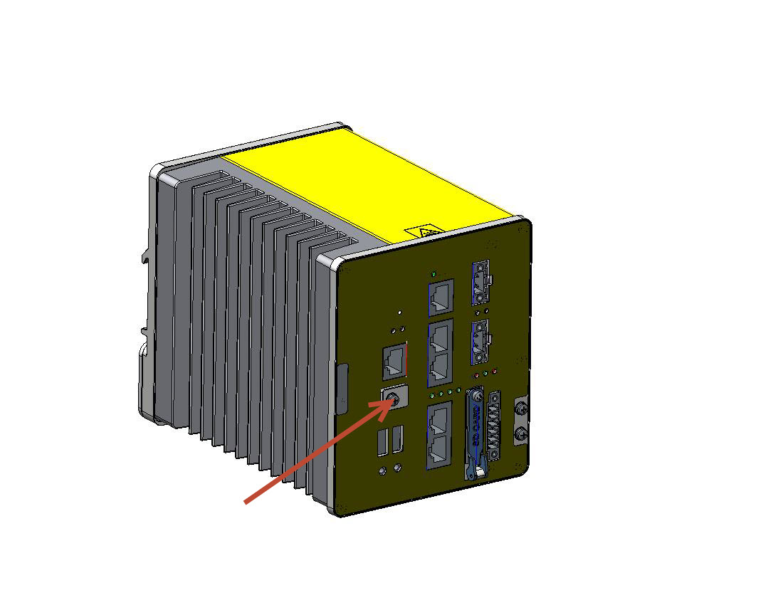
If the mini-USB connector is being used, the protective cover will need to be removed first. The red arrow in the following figure shows the location of the cover. Remove the cover with a Phillips screw driver and set it aside to be reinstalled after completing the configuration.

Figure 2. mini-USB Cover

Step 3

Connect the mini-USB side of a cable to the USB Console port on the Cisco ISA 3000.

Step 4

Connect the opposite end of the mini-USB cable to the USB port on your PC. If your PC warns you that you do not have the proper drivers to communicate with the device, you can obtain them from your computers manufacturer, or go here: https://software.cisco.com/download/home/282774227/type/282855122/release/3.1

Step 5

Start up a console terminal.

Step 6

See the initial configuration section for more details.


Connecting to DC Power

Before you begin


Warning


This product relies on the building’s installation for short-circuit (overcurrent) protection. Ensure that the protective device is rated not greater than 60 VDC minimum, 5A maximum. Statement 1005

Warning


Installation of the equipment must comply with local and national electrical codes. Statement 1074

Warning


Before performing any of the following procedures, ensure that power is removed from the DC circuit. Statement 1003

Warning


Only trained and qualified personnel should be allowed to install, replace, or service this equipment. Statement 1030

Warning


A readily accessible two-poled disconnect device must be incorporated in the fixed wiring. Statement 1022

You connect DC power to the device through the front panel connectors. The device has a dual-feed DC power supply; two connectors provide primary and secondary DC power (DC-A and DC-B).

Each power connector has an LED status indicator. The device power connectors are attached to the device chassis. Each power connector has screw terminals for terminating the DC power. All connectors are attached to the device front panel with the provided captive screws.

The power connector labeling is on the panel. The positive DC power connection is labeled “+”, and the return connection is labeled “–”.

The device can operate with a single power source or with dual power sources. When both power sources are operational, the device draws power from the DC source with the higher voltage. If one of the two power sources fail, the other continues to power the device.

To connect DC power to your Cisco ISA 3000, follow these steps:

Procedure


Step 1

Locate the two power connectors on the device front panel labeled DC-A and DC-B.

Figure 3. Power Connector

Step 2

Identify the connector positive and return DC power connections. The "+" is the Positive DC power connection, and the "-" is the Return DC power connection.

Step 3

Measure two strands of twisted-pair copper wire long enough to connect the power converter to the DC power source. For DC connections from the power converter to the DC source, use 18 to 20 AWG (2.6mm) twisted-pair copper wire.

Step 4

Using a 18-gauge (1.02mm) wire-stripping tool, strip the ground wire and both ends of the twisted pair wires to 0.25 inch (6.3 mm) ± 0.02 inch (0.5 mm). See the following figure, number 1. Do not strip more than 0.27 inch (6.8 mm) of insulation from the wires. Stripping more than the recommended amount of wire can leave exposed wire from the power and relay connector after installation.

Figure 4. Stripping the Power Connection Wire

Step 5

Remove the two captive screws that attach the power connector to the device, and remove the power connector. Remove both connectors if you are connecting to two power sources.

Step 6

On the power connector, insert the exposed part of the positive wire into the connection labeled “+” and the exposed part of the return wire into the connection labeled “–”. The "+" is the Power source positive connection, and the "-" is the Power source return connection. See the following figure.

Figure 5. Inserting Wires into the Power Connector

1

Power source positive connection

2

Power source return connection

Note

 
Ensure that you cannot see any wire lead. Only wire with insulation should extend from the connector.

Step 7

Use a ratcheting torque flathead screwdriver to torque the power connector captive screws (above the installed wire leads) to 2 in-lb (0.23 N-m). See the following figure.

Note

 
Do not over-torque the power connector’s captive screws. The torque should not exceed 2 inch-lbs (0.23 N-m).
Figure 6. Torquing the Power Connector Captive Screws

1

Power connector captive screws

Warning

 
An exposed wire lead from a DC-input power source can conduct harmful levels of electricity. Be sure that no exposed portion of the DC-input power source wire extends from the power and relay connector. Statement 122

Step 8

Connect the other end of the positive wire to the positive terminal on the DC power source, and connect the other end of the return wire to the return terminal on the DC power source.

When you are testing the device, one power connection is sufficient. If you are installing the device and are using a second power source, repeat steps 4 through 8 using the second power connector.


Attaching the DC Power Connectors to the Device

To attach the power connectors to the front panel of the device, follow these steps:


Warning


Failure to securely tighten the captive screws can result in an electrical arc if the connector is accidentally removed. Statement 397

Warning


When you connect or disconnect the power and/or alarm connector with power applied, an electrical arc can occur. This could cause an explosion in hazardous area installations. Be sure that all power is removed from the device and any other circuits. Be sure that power cannot be accidentally turned on or verify that the area is nonhazardous before proceeding. Statement 1058
  1. Insert one power connector into the DC-A receptacle on the device front panel, and the other into the DC-B receptacle.

  2. Use a ratcheting torque flathead screwdriver to tighten the captive screws on the sides of the power connectors to 2 in-lb (0.23 N-m).

  3. When you are testing the device, one power source is sufficient. If you are installing the device and are using a second power source, repeat this procedure for the second power connector (DC-B), which installs just below the primary power connector (DC-A).

  4. When you are installing the device, secure the wires coming from the power connector so that they cannot be disturbed by casual contact. For example, use tie wraps to secure the wires to the rack.

Verifying Connections

To verify that all devices are properly connected to the Cisco ISA 3000, first turn on all the connected devices, then check the LEDs. To verify Cisco ISA 3000 operation, refer to the following table:

LED

Activity

Description

System

Power Status

Off — No power

Green Steady on — Normal operation

Green Flashing — Boot up phase and POST

Red Flashing — BIOS

Red — System is not functioning properly.

MGMT

Management Port Status

Off — No link (default)

Green Steady on — Port link with no activity

Green Flashing — Transmitting and Receiving data

DC_A

DC_B

DC Power Status

Off — Power is not present

Green Steady on — Power is present on the associated circuit. (Hardware controlled)

Red Steady on — Power is not present on the associated circuit, and the system is configured for dual-input power.

Alarm Out

Alarm monitoring

Off — Alarm Out not configured or the system is off (Default)

Green Steady on — Alarm Out is configured, no alarm detected.

Red Steady on — Minor alarm detected

Red Flashing — Major alarm detected

Alarm In 1&2

Alarm monitoring

Off — Alarm Out not configured or the system is off (Default)

Green Steady on — Alarm Out is configured, no alarm detected.

Red Steady on — Minor alarm detected

Red Flashing — Major alarm detected

Ethernet Ports

Link Status

Off — No link

Green Steady on — Link is up

Green Flashing — Transmitting and Receiving data

Amber — Fault, check log.

Port 1&2 or 3&4 LEDs flashing amber together — Those two ports are in bypass mode and the system is up.

Console

Console connection status

Off — RJ-45 is being used for console

Green — Mini USB is being used for console

BYPASS

Bypass Mode Indicator

The Ethernet LAN Ports pairs 1&2 or 3&4 (copper sku only) will blink amber together every 100ms (fast blink), when there is system power.

Connecting Alarm Circuits

After the device is installed, you are ready to connect the DC power and alarm connections.

The device has two alarm input and one alarm output relay circuits for external alarms. The alarm input circuits are designed to sense if the alarm input is open or closed relative to the alarm input reference pin. Each alarm input can be configured as an open or closed contact. The alarm output relay circuit has a normally open and a normally closed contact.

Alarm signals are connected to the device through the six-pin alarm connector. Three connections are dedicated to the two alarm input circuits: alarm input 1, alarm input 2, and a reference ground. An alarm input and the reference ground wiring connection are required to complete a single alarm input circuit. The three remaining connections are for the alarm output circuit: a normally open output, a normally closed output, and a common signal. An alarm output and the common wiring connection are required to complete a single alarm output circuit.

The alarm connectors are on the device panel and are detailed in the following table:

Pin

Connection

1

Alarm Output Normally Open (NO) connection

2 (COM)

Alarm Output Common connection

3

Alarm Output Normally Closed (NC) connection

4 (IN2)

Alarm Input 2

5 (REF)

Alarm Input Reference Ground connection

6 (IN1)

Alarm Input 1


Warning


Explosion Hazard—Do not connect or disconnect wiring while the field-side power is on; an electrical arc can occur. This could cause an explosion in hazardous location installations. Be sure that power is removed or that the area is nonhazardous before proceeding. Statement 1081

Caution


The input voltage source of the alarm output relay circuit must be an isolated source and limited to less than or equal to 24 VDC, 1.0 A or 48 VDC, 0.5 A.

Note


Wire connections to the power and alarm connectors must be UL- and CSA-rated, style 1007 or 1569 twisted-pair copper appliance wiring material (AWM) wire (such as Belden part number 9318).

Wiring the External Alarms

To wire the device to an external alarm device, follow these steps:

Procedure


Step 1

Remove the captive screws that hold the alarm connector on the device, and remove the connector from the device chassis.

Step 2

Measure two strands of twisted-pair wire (18-to-20 AWG) long enough to connect to the external alarm device.

You can choose between setting up an external alarm input or output circuit.

Step 3

Use a wire stripper to remove the casing from both ends of each wire to 0.25 inch (6.3 mm) ± 0.02 inch (0.5 mm).

Do not strip more than 0.27 inch (6.8 mm) of insulation from the wires. Stripping more than the recommended amount of wire can leave exposed wire from the alarm connector after installation.

Step 4

Insert the exposed wires for the external alarm device into the connections based on an alarm input or output circuit setup.

For example, to wire an alarm input circuit, complete the IN1 and REF connections as shown in the following figure:

1

IN1 - External device connection 1

2

REF - External device connection 2

Step 5

Use a ratcheting torque flathead screwdriver to tighten the alarm connector captive screw (above the installed wire leads) to 2 in-lb (0.23 N-m).

Note

 
Do not over-torque the power and alarm connectors’ captive screws. Do not exceed 2 inch-lbs (0.23 N-m) torque.

Step 6

Repeat the above steps to insert the input and output wires of one additional external alarm device into the alarm connector.


What to do next

The following figure shows the completed wiring for two external alarm devices. The first alarm device circuit is wired as an alarm input circuit; the IN1 and REF connections complete the circuit. The second alarm device circuit is wired as an alarm output circuit that works on a normally open contact basis; the NO and COM connections complete the circuit.

Figure 7. Completed Connections for Two External Alarm Devices on the Alarm Connector

1

IN1 wired connection

2

REF wired connection

3

COM wired connection

4

NO wired connection

Attaching the Alarm Connector to the Device


Warning


Failure to securely tighten the captive screws can result in an electrical arc if the connector is accidentally removed. Statement 397

Warning


When you connect or disconnect the power and/or alarm connector with power applied, an electrical arc can occur. This could cause an explosion in hazardous area installations. Be sure that all power is removed from the device and any other circuits. Be sure that power cannot be accidentally turned on or verify that the area is nonhazardous before proceeding. Statement 1058

To attach the alarm connector to the front panel of the device:

Procedure


Step 1

Insert the alarm connector into the receptacle on the device front panel.

Step 2

Use a ratcheting torque flathead screwdriver to tighten the captive screws on the sides of the alarm connector. Torque to 2 in-lb (0.23 N-m).