Layer 2 VPN

Layer 2 VPN

Table 1. Feature History

Feature Name

Release Information

Description

Layer 2 (L2) VPN

Cisco IOS XE Catalyst SD-WAN Release 17.14.1a

Cisco Catalyst SD-WAN Control Components Release 20.14.x

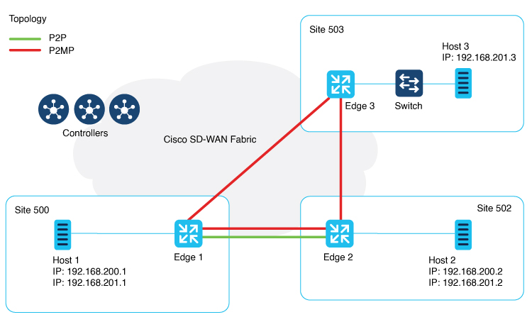
The feature adds Layer 2 VPN support on the Cisco Catalyst SD-WAN overlay network.

It allows you to configure Layer 2 point-to-point and point-to-multipoint connections within the Cisco Catalyst SD-WAN fabric.

Layer 2 (L2) VPN Multihoming and Hub-and-Spoke Support

Cisco IOS XE Catalyst SD-WAN Release 17.15.1a

Cisco Catalyst SD-WAN Manager Release 20.15.x

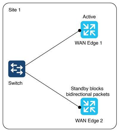
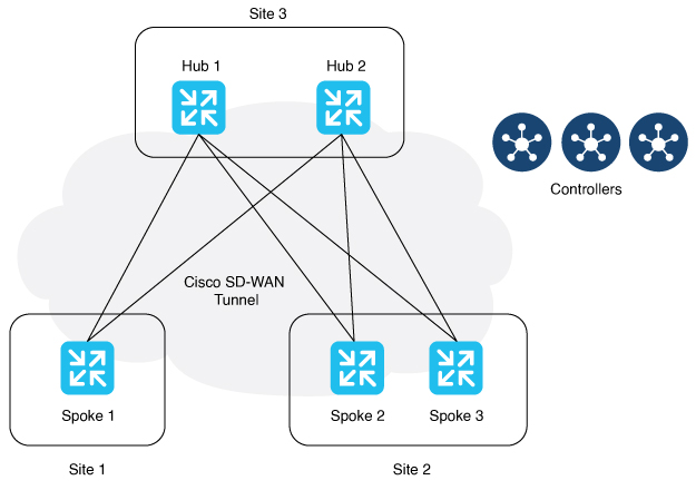
With this feature, you can configure Layer 2 VPN on multiple devices on the same site in an active-standby configuration.

This feature also enables Layer 2 connections using an indirect path, such as a hub, for point-to-multipoint connections within the Cisco Catalyst SD-WAN fabric.

Information About Layer 2 VPN Support within the Cisco Catalyst SD-WAN Overlay Network

The ​Cisco Catalyst SD-WAN solution provides Layer 3 services with security, segmentation, and scalability across the overlay network. Considering the importance of Layer 2 (L2) connectivity, particularly for legacy systems and non-IP applications, Layer 2 services are supported within the Cisco Catalyst SD-WAN overlay network. L2VPN support enables using legacy applications that require Layer 2 connectivity across the Cisco Catalyst SD-WAN fabric.

Starting from Cisco IOS XE Catalyst SD-WAN Release 17.14.1a, the following L2VPN features are supported:

  • Point-to-point L2VPN Service (P2P)

  • Point-to-Multipoint L2VPN Service (P2MP)

  • Single homing

  • Flood and Learn in WAN and LAN

  • Ingress replication for Broadcast, Unknown-unicast and Multicast (BUM)

  • Full mesh topology only

Starting from Cisco IOS XE Catalyst SD-WAN Release 17.15.1a, the following L2VPN features are supported:

  • Multihoming for P2P and P2MP

  • Hub-and-spoke topology support for L2VPN services

  • The MAC learning mode (previously the Flood and Learn in WAN and LAN) is changed to learning through OMP protocol (that is, Control Plane).

Network Topology for Layer 2 Connections

This illustration shows three sites and shows P2P (green line) and P2MP (red lines) connections between edge routers at the sites.

  • Point-to-Point (P2P): Connects sites 500 and 502 with a dedicated Layer 2 VPN. The L2VPN connection between the two sites allows Host 1 and Host 2 to interact.

  • Point-to-Multipoint (P2MP): Connects sites 500, 502, and 503 with Layer 2 VPN. Host 1 communicates with both Host 2 and Host 3 across a Layer 2 multipoint network.

The L2VPN connections use existing Cisco Catalyst SD-WAN tunnels.

Figure 1. Topology

Multihoming

Figure 2. Multihoming
The illustration shows two edge routers on the same site connected to a switch. For an (instance-id + vc), one router is active and the other is on standby. (instance-id +vc) maps to a bridge domain and a bridge-domain maps to a VLAN (or a VLAN range).

The router on standby blocks bidirectional traffic for that VLAN.

Multihoming supports L2VPN configuration on up to two edge devices on the same site, thereby providing redundancy for L2VPN service over SD-WAN.

Multihoming allows an active-standby scenario where one device is chosen as active and the other as standby. This provides automated failover. It determines which of the two edge devices should be active and which one should be on standby. When the OMP timer expires on the controller, it marks the L2VPN status route as stale, and notifies other edges.

Active and Standby Device Role Determination

The active and standby roles are decided automatically based on the following algorithm:

(SDWAN-Instance-ID + VC-ID) modular 2

If the modular result is 0, the edge with lower system-ip is selected as the active device. The edge with the higher system-ip is selected as the standby device.

If the modular result is 1, the edge with higher system-ip is selected as the active device. The edge with the lower system-ip is selected as the standby device.

Example:

There are two WAN edge devices. WAN edge 1 has a system-ip of 172.16.255.10. WAN edge 2 has a system-ip of 172.16.255.11.

For sdwan-instance-id 100, vc-id 2, WAN edge 1 with the lower system-ip is selected as the active device. WAN edge 2 is the standby device.

For sdwan-instance-id 100, vc-id 1, WAN edge 2 with the higher system-ip is selected as the active device. WAN edge 1 is the standby device.

If a failure occurs on the service side of one of the edge devices, the controller is notified about a change to the L2VPN status route, and other edge routers can switchover traffic to the new active device.

L2VPN Hub-and-Spoke Support

Minimum software releases: Cisco Catalyst SD-WAN Manager Release 20.15.1

Figure 3. Hub-and-Spoke

The preceding illustration shows P2MP Layer 2 VPN hub-and-spoke topology. In this configuration, spokes communicate with each other through the hubs. Layer 2 VPN hub-and-spoke supports Layer 2 connections using an indrect path, such as a hub.

You can enable Layer 2 VPN with only intent-based hub-and-spoke topology introduced in Cisco Catalyst SD-WAN Manager Release 20.12.1. It is used to build the hub-and-spoke topology in the network.

Layer 2 VPN hub-and-spoke supports P2MP. For more information about the intent-based hub-and-spoke feature, see Hub-and-Spoke.

Supported Platforms for Layer 2 VPN

Minimum software releases: Cisco IOS XE Catalyst SD-WAN Release 17.14.1a

All Cisco IOS XE Catalyst SD-WAN devices.

Restrictions for Layer 2 VPN

Minimum software releases: Cisco IOS XE Catalyst SD-WAN Release 17.14.1a and Cisco Catalyst SD-WAN Control Components Release 20.14.1

  • Only CLI template or CLI add-on template configuration is supported for Layer 2 VPN.

  • For both single homing and multihoming, only one LAN side interface is supported in a bridge-domain.

  • P2P configuration between two spokes is not supported. In such cases, use P2MP instead of P2P.


    Note


    P2P configuration between hub and spoke is supported.


  • Starting from Cisco IOS XE Catalyst SD-WAN Release 17.15.1a, multihoming only supports dual homing.

  • Starting from Cisco IOS XE Catalyst SD-WAN Release 17.15.1a, hub-and-spoke topology is supported for Layer 2 VPN. It is limited by:

    • No support for Point-to-Point Layer 2 VPN service between spokes.

    • Support for up to 6000 spokes and 6000 sites within the same Layer 2 VPN in hub-and-spoke topology, and

    • Support for only 256 sites within the same Layer 2 VPN in a non-hub-and-spoke design.

  • When upgrading to Cisco IOS XE Catalyst SD-WAN Release 17.15.1a or Cisco Catalyst SD-WAN Manager Release 20.15.1, you might experience minor outages on the Layer 2 VPN functionality until all participating edge routers and controllers are upgraded.

  • Due to the change of the MAC learning mode from Flood and Learn in WAN and LAN to OMP protocol (Control Plane), there is no L2VPN interconnectivity between devices running both Cisco IOS XE Catalyst SD-WAN Release 17.14.1a and Cisco IOS XE Catalyst SD-WAN Release 17.15.1a.

Configure an L2VPN on a Cisco IOS XE Catalyst SD-WAN Device Using CLI Template

Before you begin

For more information about using CLI templates, see CLI Add-On Feature Templates and CLI Templates.

Procedure


Step 1

Configure an L2VPN instance for P2P and P2MP connections.


l2vpn sdwan instance instance-id point-to-point
l2vpn sdwan instance instance-id multipoint

The instance ID is a unique identifier for each L2VPN connection, and must not overlap or be shared with any Layer 3 VRFs in the Cisco Catalyst SD-WAN fabric. For example, you cannot use L2VPN instance 10 and vrf definition 10.

Step 2

Configure a bridge-domain.

bridge-domain bridge-id

Step 3

Configure a Layer 2 interface on a Cisco IOS XE Catalyst SD-WAN device.

interface vlan-id
 service instance instance-id ethernet
  encapsulation dot1q vlan-id
  no shutdown

Note


A rewrite is used to modify the default VLAN tag. If you have not configured rewrite under service instance, dot1q must be the same at all sites participating in the Layer 2 network. The rewrite option in a Layer 2 configuration modifies the VLAN tags of packets as they ingress or egress an interface. To use the rewrite option, you need to configure Ethernet Virtual Connections (EVCs) on edge routers (Cisco ASR 1000 Series). For more information about configuring an EVC, see Configuring Ethernet Virtual Connections on a Cisco Router.


Configure Point-to-Point Layer 2 VPN Using CLI Template

Before You Begin

  • You can use one L2VPN instance ID for one or more bridge domains. It must be the same at both ends of the circuit.

    To identify a particular bridge-domain, use Virtual Circuit (VC) ID. This ID is the identifier of the virtual circuit between the Cisco IOS XE Catalyst SD-WAN devices.

  • To create a P2P pseudowire, L2VPN instance ID, and VC ID must be the same on different Cisco IOS XE Catalyst SD-WAN devices.

  • Remote-site-id is only supported for P2P configuration.

This following section provides the CLI configuration to configure P2P L2VPN services between two sites (Site A and Site B) on the Cisco Catalyst SD-WAN overlay network.

  1. Configure an Edge Router at Site A for Point-to-Point Layer 2 VPN Using CLI Template

  2. Configure an Edge Router at Site B for Point-to-Point Layer 2 VPN Using CLI Temple

For more information about using CLI templates, see CLI Add-On Feature Templates and CLI Templates.


Note


By default, CLI templates execute commands in global config mode.


Configure an Edge Router at Site A for Point-to-Point Layer 2 VPN Using CLI Template

Site A uses an edge router and connects the Ethernet interface to the L2 network that bridges to Site B.

Procedure


Step 1

Define the L2VPN instance for point-to-point service:

l2vpn sdwan instance instance-id point-to-point

Step 2

Configure the Ethernet interface:


interface interface-name
 service instance instance-id ethernet
  encapsulation dot1q vlan-id

Step 3

Define the bridge domain and associate it with the interface and L2VPN instance:


bridge-domain bridge-id
 member vlan-name service-instance instance-id
 member sdwan instance  instance-id  remote-site remote-site-id vc-id  virtual-circuit-id single-homing
Starting from Cisco IOS XE Catalyst SD-WAN Release 17.15.1a, you can specify the homing type as dual homing to enable multihoming.
bridge-domain bridge-id
member vlan-name service-instance instance-id
member sdwan instance instance-id remote-site remote-site-id vc-id virtual-circuit-id dual-homing 

Example

The following configures Site A using Cisco Catalyst 8000V Edge Software to manage traffic through GigabitEthernet5, which is linked to the Layer 2 network that provides connectivity to Site B.


l2vpn sdwan instance 100 point-to-point

interface GigabitEthernet5 
 service instance 100 ethernet
  encapsulation dot1q 2002
  !
bridge-domain 100
 member GigabitEthernet5 service-instance 100
 member sdwan-instance 100 remote-site 502 vc-id 100 single-homing

Configure an Edge Router at Site B for Point-to-Point Layer 2 VPN Using CLI Temple

Site B uses an edge router and Switchport Ethernet interface.

Procedure


Step 1

Define the L2VPN instance for point-to-point service.

l2vpn sdwan instance instance-id point-to-point

Step 2

Define the VLAN for the L2VPN.


vlan vlan-id
 name l2vpn

Step 3

Configure the VLAN interface.


interface interface-name
 service instance instance-id ethernet
  encapsulation dot1q vlan-id
  no shutdown

Step 4

Configure the Ethernet interface as an access port for VLAN.


interface interface-name
 switchport access vlan vlan-id

Step 5

Define the bridge-domain for site B and associate it with the VLAN and L2VPN instance.


bridge-domain bridge-id
 member vlan-name service-instance instance-id
 member sdwan instance  instance-id  remote-site remote-site-id vc-id  virtual-circuit-id single-homing
Starting from Cisco IOS XE Catalyst SD-WAN Release 17.15.1a, specify the homing type as dual homing to enable multihoming.
bridge-domain bridge-id
member vlan-name service-instance instance-id
member sdwan instance instance-id remote-site remote-site-id vc-id virtual-circuit-id dual-homing 

Example

The following configures Switchport GigabitEthernet 0/1/7 at Site B to connect to the interface with a Cisco ISR1100-8P device.


l2vpn sdwan instance 100 point-to-point
vlan 2002
 name L2vpn
interface Vlan2002 
 service instance 100 ethernet
  encapsulation dot1q 2002 
  no shutdown
  !
interface GigabitEthernet 0/1/7
 switchport access vlan 2002
bridge-domain 100
 member Vlan2002 service-instance 100
 member sdwan-instance 100 remote-site 500 vc-id 100 single-homing
 

After configuring the point-to-point L2VPN service on both sites, you can integrate these configuration blocks into your CLI Template or CLI Add-On Feature Template. This template can then be used to deploy the configuration across the relevant devices in the ​Cisco Catalyst SD-WAN fabric. Verify the connectivity and functionality of the L2VPN service following the deployment to confirm that the bridge between site A and site B is operational.

Configure Point-to-Multipoint Layer 2 VPN Using CLI Template

  • For more information about using CLI templates, see CLI Add-On Feature Templates and CLI Templates.

    By default, CLI templates execute commands in global config mode.

  • One L2VPN instance ID can be used by one or more bridge domains. VC ID is used to identify a particular bridge-domain.

  • L2VPN instance ID and VC ID must be the same on different edge devices.

This following section provides steps for configuring P2MP L2VPN over Cisco Catalyst SD-WAN overlay, connecting a local Layer 2 network at site A to multiple remote sites (B and C). Site A uses Gigabit Ethernet interface to connect to the Layer 2 network for bridging.

  1. Configure an Edge Router at Sites A, B, and C

  2. Configure an Edge router at site B

  3. Configure an Edge router at branch router site C

Configure an Edge Router at Sites A, B, and C

Site A is using an edge router, where an Ethernet interface is connected to the Layer 2 network that bridges to Site B and Site C.

Procedure


Step 1

Define the L2VPN instance for the multipoint service on the data center router:

l2vpn sdwan instance instance-id multipoint 

Step 2

Configure the Ethernet interface on the data center router:

interface interface-name
service instance instance-id ethernet
encapsulation dot1q vlan-id 

Step 3

Define the bridge-domain on the data center route and associate it with the interface and L2VPN instance:

bridge-domain bridge-id
member vlan-name service-instance instance-id
member sdwan instance instance-id remote-site remote-site-id vc-id virtual-circuit-id single-homing 
Starting from Cisco IOS XE Catalyst SD-WAN Release 17.15.1a, specify the homing type as dual homing to enable multihoming.
bridge-domain bridge-id
member vlan-name service-instance instance-id
member sdwan instance instance-id remote-site remote-site-id vc-id virtual-circuit-id dual-homing 

Configure an Edge Router at Site B for Point-to-Point Layer 2 VPN Using CLI Temple

Site B uses an edge router and Switchport Ethernet interface.

Procedure


Step 1

Define the L2VPN instance for point-to-point service.

l2vpn sdwan instance instance-id point-to-point

Step 2

Define the VLAN for the L2VPN.


vlan vlan-id
 name l2vpn

Step 3

Configure the VLAN interface.


interface interface-name
 service instance instance-id ethernet
  encapsulation dot1q vlan-id
  no shutdown

Step 4

Configure the Ethernet interface as an access port for VLAN.


interface interface-name
 switchport access vlan vlan-id

Step 5

Define the bridge-domain for site B and associate it with the VLAN and L2VPN instance.


bridge-domain bridge-id
 member vlan-name service-instance instance-id
 member sdwan instance  instance-id  remote-site remote-site-id vc-id  virtual-circuit-id single-homing
Starting from Cisco IOS XE Catalyst SD-WAN Release 17.15.1a, specify the homing type as dual homing to enable multihoming.
bridge-domain bridge-id
member vlan-name service-instance instance-id
member sdwan instance instance-id remote-site remote-site-id vc-id virtual-circuit-id dual-homing 

Example

The following configures Switchport GigabitEthernet 0/1/7 at Site B to connect to the interface with a Cisco ISR1100-8P device.


l2vpn sdwan instance 100 point-to-point
vlan 2002
 name L2vpn
interface Vlan2002 
 service instance 100 ethernet
  encapsulation dot1q 2002 
  no shutdown
  !
interface GigabitEthernet 0/1/7
 switchport access vlan 2002
bridge-domain 100
 member Vlan2002 service-instance 100
 member sdwan-instance 100 remote-site 500 vc-id 100 single-homing
 

After configuring the point-to-point L2VPN service on both sites, you can integrate these configuration blocks into your CLI Template or CLI Add-On Feature Template. This template can then be used to deploy the configuration across the relevant devices in the ​Cisco Catalyst SD-WAN fabric. Verify the connectivity and functionality of the L2VPN service following the deployment to confirm that the bridge between site A and site B is operational.

Configure an Edge Router at Site C for Point-to-Point Layer 2 VPN Using CLI Template

Before you begin

Repeat the same steps as for branch router C, substituting the specific interface used on site B.

Procedure


Step 1

Define the L2VPN instance for multipoint service on the branch router:

l2vpn sdwan instance instance-id multipoint 

Step 2

Define the VLAN for the L2VPN on the branch router:

vlan vlan-id
name L2vpn 

Step 3

Configure the VLAN interface on the branch router:

interface interface-name 
service instance instance-id ethernet
encapsulation dot1q vlan-id
no shutdown 

Step 4

Configure the Ethernet interface on the branch router as an access port for VLAN:

interface interface-name
switchport access vlan vlan-id 

Step 5

Define the bridge-domain on the branch router and associate it with the VLAN and L2VPN instance:

bridge-domain bridge-id
member vlan-name service-instance instance-id
member sdwan instance instance-id  vc-id virtual-circuit-id single-homing 
Starting from Cisco IOS XE Catalyst SD-WAN Release 17.15.1a, specify the homing type as dual homing to enable multihoming.
bridge-domain bridge-id
member vlan-name service-instance instance-id
member sdwan instance instance-id remote-site remote-site-id vc-id virtual-circuit-id dual-homing 

Example

This section provides an example configuration for P2MP L2VPN service within the Cisco Catalyst SD-WAN overlay network, connecting a local Layer 2 network at site A to multiple remote sites (B and C). Site A uses GigabitEthernet6 interface to connect to the L2 network for bridging.

Verify the connectivity and functionality of the P2MP L2VPN service and ensure that all sites are correctly bridged.

Site A is using a Cisco Catalyst 8000V edge router, where GigabitEthernet6 is connected to the Layer 2 network that bridges to site B and site C.

l2vpn sdwan instance 200 multipoint

vlan 2001
 name L2MPvpn

interface Vlan2001
 service instance 200 ethernet
  encapsulation dot1q 2001
  no shutdown
  !
interface GigabitEthernet 0/1/6
 switchport access vlan 2001

bridge-domain 200
 member Vlan2001 service-instance 200
 member sdwan-instance 200 vc-id 200 single-homing

Configure branch router C:

Repeat the same steps as for branch router B, substituting the specific interface used on router 503. In this example, we have used the GigabitEthernet 0/1/6 interface.

l2vpn sdwan instance 200 multipoint

vlan 2001
 name L2MPvpn

interface Vlan2001
 service instance 200 ethernet
  encapsulation dot1q 2001
  no shutdown
  ! 
bridge-domain 200
 member Vlan2001 service-instance 200
 member sdwan-instance 200 vc-id 200 single-homing

Configure Layer 2 VPN Switchport Using CLI Template

If your device such as Cisco ISR1121-8P or similar has embedded switchports and you want to use one of them for the L2VPN services, configure a VLAN interface first and then assign that VLAN to your switchport as described in this section.

To support a Layer 2 switchport, configure a service instance in the VLAN interface. In the VLAN interface, a packet always has the dot1q tag even when the Layer 2 switchport is configured with switchport mode access. Therefore, the dot1q tag is mandatory in the service instance of the VLAN interface.

This following section provides steps to configure a Layer 2 switchport for P2MP (applicable for devices with embedded switchports). You can also configure a Layer 2 switchport for P2P by updating the Layer 2 VPN ​instance command.

Site A is using an edge router, where the Ethernet interface is connected to the Layer 2 network that bridges to Site B and Site C.

Procedure


Step 1

Define the Layer 2 VPN instance for multipoint service on the branch routers:

l2vpn sdwan instance instance-id multipoint 

Step 2

Define the VLAN for the Layer 2 VPN on the branch routers:

vlan vlan-id
name l2vpn 

Step 3

Configure the Ethernet interface on the routers:

interface interface-name 

Step 4

Set the switch port access VLAN and switchport mode to access to accept traffic only from the specified VLAN:

switchport access Vlan vlan-id 

Step 5

Configure the VLAN interface on a router and disable the IP address assignment

interface interface-name
no ip address
service instance instance-id ethernet
encapsulation dot1q vlan-id 

Step 6

Define the bridge-domain on the data center router and associate it with the interface and L2VPN instance:

bridge domain bridge-id
member vlan-name service-instance instance-id
member sdwan instance instance-id vc-id virtual-circuit-id single homing 

Example

The following configures a Layer 2 VPN Switchport to integrate a multipoint SD-WAN instance and bridge-domain. This configuration sets up GigabitEthernet0/1/2 as an access port for VLAN 201.

l2vpn sdwan instance 200 multipoint
 
interface GigabitEthernet0/1/2
 switchport access Vlan 201
 switchport mode access
 
interface Vlan201
 no ip address
 service instance 200 ethernet
  encapsulation dot1q 201
  !

bridge-domain 201 
 member Vlan201 service-instance 200
 member sdwan-instance 200 vc-id 201 single-homing

Verify Layer 2 VPN Using CLI

Follow these procedures to verify a Layer 2 VPN configuration on a Cisco Catalyst SD-WAN overlay network.

  1. View a Layer 2 VPN Status

  2. View L2VPN Information Learned Through OMP Route on a Cisco Catalyst SD-WAN Controller

  3. View Bridge-Domain Information

  4. View Cisco Catalyst SD-WAN Flood List Information and Packet Counters in Data Plane

  5. View Packet Counters in Data Plane

View a Layer 2 VPN Status

Minimum Supported Releases: Cisco IOS XE Catalyst SD-WAN Release 17.14.1a, Cisco Catalyst SD-WAN Manager Release 20.14.1

Procedure


Use the show l2vpn sdwan [instance instance-id][vc-id vc-id] command to view the remote peer information, system IP, status, and so on.


Example

The following example is for a Cisco IOS XE Catalyst SD-WAN device.

Device# show l2vpn sdwan instance 13 vc-id 13
VC_ID: 13 Bridge-domain: 13
Local l2vpn status: UP
Local Pseudoports: GigabitEthernet7 service instance 13

View L2VPN Information Learned Through OMP Route on a Cisco Catalyst SD-WAN Controller

Procedure


Use the show sdwan omp l2-routes[vpn vpn-id] [vc-id vc-id] command shows the specific L2-route or path learned in the specific VPN and virtual circuit. If the vpn and vc-id are not included, the command shows Layer 2 routes learned through OMP from all VPNs across the Cisco Catalyst SD-WAN fabric.


Example

The following is a sample output from the show omp l2-routes command displaying Layer 2 routes learned through OMP for Cisco Catalyst SD-WAN Controllers.

Device# show omp l2-routes | tab
C   -> chosen
I   -> installed
Red -> redistributed
Rej -> rejected
L   -> looped
R   -> resolved
S   -> stale
Ext -> extranet
Inv -> invalid
Stg -> staged
IA  -> On-demand inactive
U   -> TLOC unresolved

                                                                                                                                   REMOTE  
                                     ROUTE                   IP                   SITE                   PATH                      SITE    
VPN    VC ID        ORIGINATOR       TYPE   MAC ADDRESS      ADDRESS  VPN TYPE    ID    FROM PEER        ID     LABEL    STATUS    ID      
-------------------------------------------------------------------------------------------------------------------------------------------
12     12           172.16.255.15    vpn    0000.0000.0000   ::       p2p         500   172.16.255.15    66     1004     C,R       501     
                                                                                        172.16.255.15    69     1004     C,R       501     
                                                                                        172.16.255.20    1      1004     C,R       501     
                                                                                        172.16.255.20    2      1004     C,R       501     
12     12           172.16.255.27    vpn    0000.0000.0000   ::       p2p         501   172.16.255.20    1      1014     C,R       500     
                                                                                        172.16.255.27    70     1014     C,R       500     
13     13           172.16.255.15    vpn    0000.0000.0000   ::       multipoint  500   172.16.255.15    66     1006     C,R       -       
                                                                                        172.16.255.15    69     1006     C,R       -       
                                                                                        172.16.255.20    1      1006     C,R       -       
                                                                                        172.16.255.20    2      1006     C,R       -       
13     13           172.16.255.27    vpn    0000.0000.0000   ::       multipoint  501   172.16.255.20    1      1016     C,R       -       
                                                                                        172.16.255.27    70     1016     C,R       -       
13     13           172.16.255.32    vpn    0000.0000.0000   ::       multipoint  503   172.16.255.20    1      1007     C,R       -       
                                                                                        172.16.255.32    71     1007     C,R       -       
14     1            172.16.255.27    vpn    0000.0000.0000   ::       multipoint  501   172.16.255.20    1      1018     C,R       -       
                                                                                        172.16.255.27    70     1018     C,R       -       
15     1            172.16.255.15    vpn    0000.0000.0000   ::       p2p         500   172.16.255.15    66     1020     C,R       501     
                                                                                        172.16.255.15    69     1020     C,R       501     
                                                                                        172.16.255.20    1      1020     C,R       501     
                                                                                        172.16.255.20    2      1020     C,R       501     
15     1            172.16.255.27    vpn    0000.0000.0000   ::       p2p         501   172.16.255.20    1      1020     C,R       500     
                                                                                        172.16.255.27    70     1020     C,R       500     

View Bridge-Domain Information

Procedure


Use the show platform software sdwan ftmd bridge-domain command on a device to verify information related to bridge domains within the context of Forwarding Table Management Daemon (FTMD).


Example

The following is a sample output from the show platform software sdwan ftmd bridge-domain command that displays information related to bridge domains within the context of Forwarding Table Management Daemon (FTMD).

Device# show platform software sdwan ftmd bridge-domain 
L2vpn Bridge-domain 12 Table:
  sdwan efp dpidx: 4210708(0x404014)
  Label: 1004 lbl-nhop-id: 196611 (binosId=0xf830003f)
  Bum Label: 1005 bum-lbl-nhop-id: 196612 (binosId=0xf830004f)
  Remote Site Table(1 entries in total):
    remote-site-id: 501 sla-nhop-id: 29 (binosId=0xf80001df)

L2vpn Bridge-domain 13 Table:
  sdwan efp dpidx: 4210709(0x404015)
  Label: 1006 lbl-nhop-id: 196613 (binosId=0xf830005f)
  Bum Label: 1007 bum-lbl-nhop-id: 196614 (binosId=0xf830006f)
  Remote Site Table(2 entries in total):
    remote-site-id: 501 sla-nhop-id: 30 (binosId=0xf80001ef)
remote-site-id: 503 sla-nhop-id: 33 (binosId=0xf800021f)

View Cisco Catalyst SD-WAN Flood List Information and Packet Counters in Data Plane

Procedure


Use the show platform hardware qfp active feature bridge-domain datapath bridge-domain-id sdwan-flood-list command to verify information related to ​Cisco Catalyst SD-WAN flood list information.


Example

The following is a sample output from the show platform hardware qfp active feature bridge-domain datapath bridge-domain-id sdwan-flood-list command that displays the ​Cisco Catalyst SD-WAN flood list information.

Device#show platform software sdwan ftmd bridge-domain 
L2vpn Bridge-domain 12 Table:
  sdwan efp dpidx: 4210708(0x404014)
  Label: 1004 lbl-nhop-id: 196611 (binosId=0xf830003f)
  Bum Label: 1005 bum-lbl-nhop-id: 196612 (binosId=0xf830004f)
  Remote Site Table(1 entries in total):
    remote-site-id: 501 sla-nhop-id: 29 (binosId=0xf80001df)

L2vpn Bridge-domain 13 Table:
  sdwan efp dpidx: 4210709(0x404015)
  Label: 1006 lbl-nhop-id: 196613 (binosId=0xf830005f)
  Bum Label: 1007 bum-lbl-nhop-id: 196614 (binosId=0xf830006f)
  Remote Site Table(2 entries in total):
    remote-site-id: 501 sla-nhop-id: 30 (binosId=0xf80001ef)
remote-site-id: 503 sla-nhop-id: 33 (binosId=0xf800021f)

View Packet Counters in Data Plane

Procedure


Use the show platform hardware qfp active feature bridge-domain datapath bridge-id command to verify information related to a QuantumFlow Processor (QFP) hardware module packet counters for a specific bridge domain within the data path.


Example

The following is a sample output from the show platform hardware qfp active feature bridge-domain datapath bridge-id command to display a QFP hardware module packet counters for a specific bridge domain within the data path.

Device# show platform hardware qfp active feature bridge-domain datapath 200
QFP L2BD Bridge Domain information                                                                 
                                                                                                                                                                                             
BD id                  : 200                                                                       
State enabled          : Yes                                                                       
Aging timeout (sec)    : 300                                                                       
Aging active entry     : Yes                                                                       
Max mac limit          : 65536                                                                     
Unkwn mac limit flood  : Yes                                                                       
mac_learn_enabled      : Yes                                                                       
mac_learn_controled    : No                                                                        
Unknown unicast olist  : Yes                                                                       
otv_aed_enabled : No                                                                               
otv_enabled : No                                                                                   
mcast_snooping_enabled : No                                                                        
Feature : sdwan                                                                                    
SISF snoop protocols   : None                                                                      
Sdwan instance id      : 200                                                                       
Mac learned            : 0                                                                         
BDI outer vtag         : 00000000                                                                  
BDI inner vtag         : 00000000                                                                  
                                                                                                   
Replication tree info:                                                                             
  Global replication    : depth encode 0X1000001, (head 0XE4E90000)                                
  Split-horizon-group 0 : depth encode 00000000, (head 00000000)                                   
  Split-horizon-group 1 : depth encode 00000000, (head 00000000)
Bridge Domain statistics
                                                                                                   
Total bridged                pkts : 0          bytes: 0                                            
Total unknown unicast        pkts : 0          bytes: 0                                            
Total broadcasted            pkts : 0          bytes: 0                                            
Total to BDI                 pkts : 0          bytes: 0                                            
Total injected               pkts : 0          bytes: 0                                            
Total mac-sec violation drop pkts : 0          bytes: 0                                            
Total mac-sec move drop      pkts : 0          bytes: 0                                            
Total mac-sec unknown drop   pkts : 0          bytes: 0                                            
Total source filter drop     pkts : 0          bytes: 0                                            
Total bfib policy drop       pkts : 0          bytes: 0                                            
Total replication start drop pkts : 0          bytes: 0                                            
Total recycle tail drop      pkts : 0          bytes: 0                                            
Total static MAC move drop   pkts : 0          bytes: 0                                            
Total BD disabled drop       pkts : 0          bytes: 0                                            
Total STP state drop         pkts : 0          bytes: 0                                            
Total UUF suppression drop   pkts : 0          bytes: 0                                            
Total sisf ctrl punt         pkts : 0          bytes: 0                                            
Total sisf ctrl drop         pkts : 0          bytes: 0                                            
Total p2p lan to wan         pkts : 0          bytes: 0                                            
Total p2p wan to lan         pkts : 0          bytes: 0 

Monitor Configured Layer 2 VPN Using CLI

The following is a sample output from the show l2vpn sdwan all command. The following examples show the configuration and status information for L2VPN instances within a ​Cisco Catalyst SD-WAN overlay network. The output includes details for both point-to-point (P2P) and point-to-multipoint (P2MP) topologies.

Example 1
Device#show l2vpn sdwan all                          
L2VPN sdwan Instance : 100
VPN Type : point-to-point
  VC_ID: 100 Bridge-domain: 100 UP
    Local l2vpn status: UP
    Local Pseudoports: GigabitEthernet5 service instance 100
    Remote Site: 53
      System IP          status       up/down    color           encap    label  DF
      10.100.31.53       DOWN         00:15:04   public-internet ipsec    1023   N/A                 
Example 2
Device#show l2vpn sdwan all
L2VPN sdwan Instance : 200
VPN Type : multipoint
IP Local-learning    : Disabled
Flooding Suppression : Disabled
  VC_ID: 200 Bridge-domain: 200 UP
    Local l2vpn status: UP
    Local Pseudoports: GigabitEthernet5 service instance 200
    Remote Site: 50
      System IP          status       up/down    color           encap    label  DF
      10.100.31.50       UP           00:04:14   public-internet ipsec    1008   N/A                 

    Remote Site: 53
      System IP          status       up/down    color           encap    label  DF
      10.100.31.53       UP           00:15:00   public-internet ipsec    1025   N/A                 

The following is a sample output from the show l2vpn sdwan instance instance-id vc-id vc-idpeers command. The following examples show information about a specific ​Cisco Catalyst SD-WAN L2VPN instance (instance 200) and its associated virtual circuit (vc-id 200), including details about its peer connections.

show l2vpn sdwan instance instance-id vc-id vc-id peers 
Example 1

Device1#show l2vpn sdwan instance 200 vc-id 200 peers 
    Remote Site: 50   MACs Learn: 0
      System IP          status       up/down    color           encap    label  DF
      10.100.31.50       UP           00:19:54   public-internet ipsec    1008   N/A                 
    Remote Site: 53   MACs Learn: 0
      System IP          status       up/down    color           encap    label  DF
      10.100.31.53       UP           00:30:40   public-internet ipsec    1025   N/A 
              
Example 2
Device#show l2vpn sdwan instance 200 vc-id 200 peers 
     Remote Site: 1   MACs Learn: 0
      System IP          status       up/down    color           encap    label  DF
      10.100.31.1        UP           00:30:13   public-internet ipsec    1014   N/A