Overview of the Cisco 5400 Enterprise Network Compute System

About the Cisco 5400 Enterprise Network Compute System


Note

The documentation set for this product strives to use bias-free language. For purposes of this documentation set, bias-free is defined as language that does not imply discrimination based on age, disability, gender, racial identity, ethnic identity, sexual orientation, socioeconomic status, and intersectionality. Exceptions may be present in the documentation due to language that is hardcoded in the user interfaces of the product software, language used based on standards documentation, or language that is used by a referenced third-party product.


The Cisco 5400 Enterprise Network Compute System (ENCS) combines routing, switching, storage, processing, and a host of other computing and networking activities into a compact one Rack Unit (RU) box. This high-performance unit achieves this goal by providing the infrastructure to deploy virtualized network functions while at the same time acting as a server that addresses processing, workload, and storage challenges.

Cisco 5400 Series Enterprise Network Compute System Chassis

Chassis - Front Panel

Figure 1. Front Panel of the Cisco 5400 ENCS

1.

Power on/off switch

2

Integrated LAN ports - optional PoE support is available for some models

3

VGA connector

4

USB port

5

Serial console port for CPU

6

Ethernet management port for CPU

7

Front panel Gigabit Ethernet WAN ports

8

LEDs for front panel Gigabit Ethernet WAN ports

9

Network Interface Module (NIM)

10

Drive bay 0

11

Drive bay 1

12

Ethernet management port for CIMC

13

Serial console port for CIMC


Note

WAN ports must only be used for WAN functions, and LAN ports must only be used for LAN functions. If you require any additional LAN or WAN connectivity with Cisco ISRv or Catalyst 8000v, install the Cisco Network Interface Modules (NIMs).


Chassis - Bezel Side

Figure 2. Bezel View of the Cisco 5400 ENCS

1

Fan vents

2

Modular power supply

3

Removable bezel

Chassis - Internal View

Figure 3. Internal View of the Cisco 5400 ENCS


Table 1.

1

PoE daughter card

2

Modular power supply

3

DDR4 DIMM slots on motherboard - 2

4

RAID card

5

M.2 storage module on motherboard

6

Drive bays for hard drives and solid-state drives (SSDs).

7

Network Interface Module

Safety Warnings


DANGER

IMPORTANT SAFETY INSTRUCTIONSThis warning symbol means danger. You are in a situation that could cause bodily injury. Before you work on any equipment, be aware of the hazards involved with electrical circuitry and be familiar with standard practices for preventing accidents. Use the statement number provided at the end of each warning to locate its translation in the translated safety warnings that accompanied this device. Statement 1071SAVE THESE INSTRUCTIONS


DANGER

Ultimate disposal of this product should be handled according to all national laws and regulations. Statement 1040


DANGER

Only trained and qualified personnel should be allowed to install, replace, or service this equipment. Statement 1030


Warning

Read the installation instructions before you connect the system to its power source. Statement 1004


Warning

Ultimate disposal of this product should be handled according to all national laws and regulations. Statement 1040


Warning

Installation of the equipment must comply with local and national electrical codes. Statement 1074


Warning

To comply with the Class A emissions requirements shielded twisted pair T1/E1 cables must be used for SPA-8-Port Channelized T1/E1 SPA (SPA-8XCHT1/E1) on the router. EN55022/CISPR22 Statement


Warning

To comply with Class A emissions requirements- shielded management Ethernet, CON, and AUX cables on the router must be used.


Warning

Power cable and AC adapter - When installing the product, please use the provided or designated connection cables/power cables/AC adaptors. Using any other cables or adapters could cause a malfunction or a fire. Electrical Appliance and Material Safety Law prohibits the use of certified cables (that have the ‘UL’ shown on the code) for any other electrical devices than products designated by Cisco. The use of cables that are certified by Electrical Appliance and Material Safety Law (that have ‘PSE’ shown on the code) is not limited to Cisco-designated products. Statement 371


Warning

This product relies on the building’s installation for short-circuit (overcurrent) protection. Ensure that the protective device is rated not greater than: AC power supplies for the Cisco 4451-X ISR. Statement 1005


Warning

This unit may have more than one power supply connection. All connections must be removed to de-energize the unit. Statement 1028


Warning

This equipment must be grounded. Never defeat the ground conductor or operate the equipment in the absence of a suitably installed ground conductor. Contact the appropriate electrical inspection authority or an electrician if you are uncertain that suitable grounding is available. Statement 1024


Warning

Class 1 LED product. Statement 1027


Warning

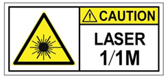
Class I(CDRH) and Class 1M (IEC) laser products. Statement 1055


Warning

Invisible laser radiation may be emitted from the end of the unterminated fiber cable or connector. Do not view directly with optical instruments. Viewing the laser output with certain optical instruments (for example, eye loupes, magnifiers, and microscopes) within a distance of 100 mm may pose an eye hazard. Statement 1056


Warning

There is the danger of explosion if the battery is replaced incorrectly. Replace the battery only with the same or equivalent type recommended by the manufacturer. Dispose of used batteries according to the manufacturer’s instructions. Statement 1015


Warning

To prevent the system from overheating, do not operate it in an area that exceeds the maximum recommended ambient temperature of: 40 degrees C. Statement 1047


Warning

Blank faceplates and cover panels serve three important functions: they prevent exposure to hazardous voltages and currents inside the chassis; they contain electromagnetic interference (EMI) that might disrupt other equipment; and they direct the flow of cooling air through the chassis. Do not operate the system unless all cards, faceplates, front covers, and rear covers are in place. Statement 1029


Warning

This unit might have more than one power supply connection. All connections must be removed to de-energize the unit. Statement 1028


Warning

Hazardous network voltages are present in WAN ports regardless of whether power to the unit is OFF or ON. To avoid electric shock, use caution when working near WAN ports. When detaching cables, detach the end away from the unit first. Statement 1026


Warning

Before opening the unit, disconnect the telephone-network cables to avoid contact with telephone-network voltages. Statement 1041


Warning

Do not use this product near water; for example, near a bath tub, wash bowl, kitchen sink or laundry tub, in a wet basement, or near a swimming pool. Statement 1035


Warning

Never install telephone jacks in wet locations unless the jack is specifically designed for wet locations. Statement 1036


Warning

No user-serviceable parts inside. Do not open. Statement 1073


Warning

Never touch uninsulated telephone wires or terminals unless the telephone line has been disconnected at the network interface. Statement 1037


Warning

Avoid using a telephone (other than a cordless type) during an electrical storm. There may be a remote risk of electric shock from lightning. Statement 1038


Warning

To report a gas leak, do not use a telephone in the vicinity of the leak. Statement 1039


Hardware Features - Standard

  • Integrated LAN ports: There are eight integrated LAN ports. These ports can provide Power over Ethernet (PoE) if you have purchased a model that supports PoE power supply. These ports must only be used for LAN functions.
  • Integrated WAN ports: There are 2 to 4 Gigabit Ethernet (GE) WAN ports (dual-mode RJ-45 and SFP). These ports must only be used for WAN functions.
  • USB 3.0 port: You can use this port to connect a mouse, keyboard, or any other USB device. Using a USB hub, you can connect more than one USB device to this port. Because this port is backward compatible, you can also use an older version of USB devices on this port.

  • VGA connector: You can use this port to connect a monitor to the device. It supports a display resolution of up to 1600 x 1200 16bpp @ 60Hz.

  • Ethernet management port for CIMC: Cisco Integrated Management Controller (CIMC) is the component in the device that monitors the health of the entire system.

  • Ethernet management port for CPU: Use this port to connect to the CPU in your device.

  • Front panel Gigabit Ethernet ports: This is a set of two dual ports. For each RJ45 port, there is a corresponding fiber optic port. At a given time, the user can use either the RJ45 connection or the corresponding fiber optic port.

  • Serial console port for CPU: This serial port provides a connection to initially configure the main system's CPU, including the NFVIS software that runs there, using a traditional serial terminal. The terminal should be configured for 9600 8-N-1.

  • Serial Console port for CIMC: This serial port provides a connection to initially configure the CIMC using a traditional serial terminal. The terminal should be configured for 9600 8-N-1.


Note

The speed and duplex configurations are dependent on the peer configuration. If the peer is set at a certain speed and duplex, NFVIS port is set to match that speed. Not all ports on ENCS 5000 series hardware devices support Automatic medium-dependent interface crossover (auto-MDIX) feature. Based on the port connected to the ENCS device, the cable type used to connect to the peer and the speed or duplex settings on the peer, you can try straight through and cross over cable.


LEDs for Gigabit Ethernet WAN Ports

The front panel Gigabit Ethernet WAN ports GE0-0 and GE0-1 (numbered 7 in Figure 1) are a set of two dual ports: for every RJ45 port, there is a corresponding fiber optic port. There are four LEDs for the front panel Gigabit Ethernet ports (numbered 8 in Figure 1). The first two LEDs are for the first set of ports and the last two LEDs are for the second set of ports. If both RJ45 and fiber optic ports are enabled when the system boots, the fiber optic port is used and the RJ45 port is disabled.

Figure 4. LEDs for Gigabit Ethernet WAN Ports


The LEDs labeled EN indicates whether the corresponding ports are enabled.

The frequency of the blinks of the LEDs labeled S shows the speed of the corresponding ports. This table maps the blink frequency of a LED to the speed of the corresponding port.

Blink Frequency

Speed

No blink

No link

1 blink

10Mbps

2 blinks

100Mbps

3 blinks

1000Mbps

Front Panel LED Status

Table 2. Front Panel LED Status

No.

LED Label

Color

Behavior

1

System boot LED

Amber

BMC boot complete, Intel powered down

Blinking amber

BMC booting, Intel powered down

Green

BMC boot complete, Intel powered up

Blinking green

BMC rebooting, Intel powered up

2

System status LED

Amber

A fault is detected in the system.

Green

Normal system operation.

3

LAN port

Blinking green

TXD/RXD data.

Amber

POE fault, implies no link.

4

BMC management port speed LED

Blinking green

Blink frequency indicates port speed:

1 blink - 10 Mbps link speed

2 blink - 100 Mbps link speed

3 blink - 1000 Mbps link speed

5

BMC management port link LED

Green

Ethernet cable present and link established

6

Management port speed LED

Blinking green

Blink frequency indicates port speed:

1 blink - 10 Mbps link speed

2 blink - 100 Mbps link speed

3 blink - 1000 Mbps link speed

7

Management port link LED

Green

Ethernet cable present and link established

8

WAN port speed LED

Blinking green

Blink frequency indicates port speed:

1 blink - 10 Mbps link speed

2 blink - 100 Mbps link speed

3 blink - 1000 Mbps link speed

9

WAN port link LED

Green

Ethernet cable present and link established

10

WAN port SFP enable LED

Green

Indicates SFP module detected

Amber

Indicates SFP is not detected or at fault

11

WAN port SFP speed LED

Blinking green

Blink frequency indicates port speed:

3 blink - 1000 Mbps link speed

12

HDD status LED

Green

HDD present

Blinking green

HDD is in rebuilt state.

Amber

HDD is in a fault state

Blinking amber

HDD is in a PFA alert state

13

HDD activity LED

Blinking green

The hard drive is reading or writing data.

Bazel Side LED Status

Table 3. Bazel Side LED Status

No.

LED Label

Color

Behavior

1

RAID status

Blue

RAID card is present and working

Amber

RAID card is present and not operating

2

Integrated services processor status

Blue

Present and functioning

Amber

Present and not functioning or faulted

3

Temperature status

Blue

All temperature sensors in the system are working

Amber

One or two temperature sensors are not working

4

System status

Blue

Normal system operations

Amber

A fault has been detected in the system.

5

System power

Blue

System power is ok.

Blinking amber

System is powering up.

6

Power supply with PoE status

Blue

PSU on and providing power.

Amber

PSU is on but in power failure condition

7

SSD slot status

Blue

Present.

Amber

Present with failure.

8

Fan status

Blue

All fans are operating.

Amber

One fan has stopped working.

Blinking amber

Two or more fans have stopped.

9

eMMC/SD flash status

Blinking blue

Present and currently being used

Amber

Fault detected

10

eMMC/SD flash status

Blue

BMC boot is complete, intel is powered up

Blinking Blue

BMC is rebooting, intel is powered up

Amber

BMC boot is complete, intel powered down.

Blinking amber

BMC is booting, intel powered down.

11

Cisco logo

Blue

System is powered on.

12

PSU failure

Amber

PSU in failure mode.

Hardware Features - Replaceable and Upgradable Units

The replaceable and upgradable units of the Cisco 5400 ENCS are:

  • Power supply: The power supply provides AC power. The ENCS5406/K9 device supports only the non-PoE power supply option. This means the LAN ports of this device cannot provide Power over Ethernet (PoE). The ENCS5408/K9 and ENCS5412/K9 devices support both the PoE and non-PoE power supply options. If you want to upgrade from a non-POE power supply to a POE power supply, you can do that by replacing the power supply unit. The reverse is also possible - replacing a POE power supply with a non-POE power supply. The power supply can supply a total of 250 watts of inline power across the 8 PoE capable ports in the system; a maximum of 30 watts of PoE power per port and 60 watts of UPoE power per port.

  • Network Interface Module (NIM): You can install a NIM in the NIM slot. Similarly when not needed, you can remove the NIM from the NIM module. The device supports only one NIM at a time. The following NIMs are currently supported:

    Table 4. Supported NIMs

    NIM

    Product Module

    Minimum Software

    LTE

    NIM-4G-LTE-VZ

    NFVIS 3.6.1

    ISRv 16.6.1

    NIM-4G-LTE-ST

    NIM-4G-LTE-NA

    NIM-4G-LTE-GA

    NIM-4G-LTE-LA

    NIM-LTEA-EA

    NIM-LTEA-LA

    T1/E1 Data

    NIM-1MFT-T1/E1

    NFVIS 3.6.1

    ISRv 16.6.1

    NIM-2MFT-T1/E1

    NIM-4MFT-T1/E1

    NIM-8MFT-T1/E1

    NIM-1CE1T1-PRI

    NIM-2CE1T1-PRI

    NIM-8CE1T1-PRI

    Asynchronous

    NIM-16A

    NFVIS 3.8.1

    ISRv 16.8.1

    NIM-24A

    T1/E1 Voice

    Same as T1/E1 Data PID List

    NFVIS 3.9.1

    ISRv 16.9.1

    DSL

    NIM-VA-B

    NFVIS 3.9.1

    ISRv 16.10.1

    NIM-VAB-A

    NIM-VAB-M

    GE

    NIM-1GE-CU-SFP

    NFVIS 3.9.1

    ISRv 16.9.1

    NIM-2GE-CU-SFP

    For more information on how to configure the voice module NIMs, refer Configuring the Cisco Fourth-Generation T1/E1 Voice and WAN Network Interface Module

  • Drive bays: There are two drive bays. You can choose to use one of them, both of them, or none of them. The types of storage modules that each of these bays can currently hold are:

    • 480GB 2.5" SATA SSD

    • 960GB 2.5" SATA SSD

    • 1TB 2.5" SATA HDD

    • 2TB 2.5" SATA HDD


    Note

    This list shows the storage modules that are currently supported. More types of storage modules may be supported in the future.


  • M.2 storage module: This is a high capacity storage component on the motherboard. The OS is installable in this module. The storage capacity of this module is upgradeable. The different storage capacities that are currently available for this module are 64GB, 100GB, 200GB, and 400GB. Other storage capacities might be made available in the future.

  • DDR4 DIMM Slots: There are two DDR4 dual in-line memory module (DIMM) slots on the motherboard. Each slot can hold 8 GB, 16 GB, or 32 GB memory module. The memory module in each of the slots can be upgraded to a maximum of 32 GB. As a result, you can have a maximum capacity of 64 GB DIMM.

  • RAID Card: The RAID card improves the performance of the hard drive. The RAID card is installed in the Internal Service Processor (ISP) module of the motherboard.

  • RMA: Return Material Authorization (RMA) Support allows you to move M.2 SSD, memory, disk drives, RAID card, NIM, and power supply from one system to another system while keeping the configuration and data. This feature is supported of like-to-like systems and the two systems must have the same versions of firmware. In case the two systems do not have the same versions of firmware, you can upgrade the firmware after swapping the hardware components. The following firmware versions are supported in RMA:

    Table 5.

    firmware compatible case

    firmware incompatible case

    original system

    new system

    original system

    new system

    FPGA

    1.6

    1.6

    1.6

    1.4

    BIOS

    2.4

    2.4

    2.4

    1.2

    CIMC

    3.2.3

    3.2.3

    3.2.3

    3.1.4

Models

The Cisco 5400 ENCS is available in these models:

Product ID

Description

ENCS5406/K9

This device has a 6 core CPU. This system does not support a PoE power supply.

ENCS5408/K9

This device has an 8 core CPU.

ENCS5412/K9

This device has a 12 core CPU.


Note

With the exception of the CPU capacity and the power supply unit, all other hardware features (standard, replaceable and upgradable) are common across all models.


Table 6. Service Spares

Product ID

ENCS5406P/K9

ENCS5408P/K9

ENCS5412P/K9


Note

Service spares are chassis with no memory or disk.


SFP Modules

This section provides information on Cisco Small Form-Factor Pluggable (SFP) Modules in Cisco ENCS 5400. The switch Gigabit Ethernet SFP and SFP+ modules provide copper or optical connections to other devices. These modules are hot-swappable and provide the uplink interfaces. The SFP modules have fiber-optic LC connectors or RJ-45 copper connectors.

Use only supported SFP modules on the switch. Each module has an internal serial EEPROM that is encoded with security information.


Note

If non-supported SFP is plugged into the system, you need to reboot the system after removing the non-supported SFP for other SFPs to work normally.


Caution

Pluggable optical modules comply with IEC 60825-1 Ed. 3 and 21 CFR 1040.10 and 1040.11 with or without exception for conformance with IEC 60825-1 Ed. 3 as described in Laser Notice No. 56, dated May 8, 2019. Statement 1255


The Cisco ENCS 5400 supports the following SFP modules:

Part Number

Description

GLC-LH-SMD

Cisco 1000BASE-LX/LH SFP module for MMF 1 and SMF, 1300-nm wavelength, commercial operating temperature range.

GLC-SX-MMD

Cisco 1000BASE-SX SFP module for MMF, 850-nm wavelength, extended operating temperature range.

SFP-GE-S

Cisco 1000BASE-SX SFP module for MMF, 850-nm wavelength, extended operating temperature range.


1  A mode-conditioning patch cord, as specified by the IEEE standard, is required. Using an ordinary patch cord with MMF, 1000BASE-LX/LH SFP transceivers, and a short link distance can cause transceiver saturation, resulting in an elevated bit error rate (BER). When using the LX/LH SFP transceiver with 62.5-micron diameter MMF, you must also install a mode-conditioning patch cord between the SFP transceiver and the MMF cable on both the sending and receiving ends of the link. The mode-conditioning patch cord is required for link distances greater than 984 feet (300 m).