Platform Specific Configurations

ENCS Switch Configuration

Access to the ENCS switch is restricted through Consent Token. Consent Token is a security feature that is used to authenticate the network administrator of an organization to access system shell with mutual consent from the network administrator and Cisco Technical Assistance Centre (Cisco TAC).


Note

From the switch console, there is access to debug mode and an advanced debug mode. Credentials of the local user are synchronized to access debug mode. Advanced debug uses unique credentials for each device that allows for additional debugging options for Cisco engineering. To enter either debug mode permission must be granted through Consent Token.


ENCS Switch Portal Configuration

Switch Settings

The Switch option from the Cisco Enterprise NFVIS portal allows you to configure STP/RSTP, VLAN on specified ranges, RADIUS based authentication, and port channel load balancing for various switch ports. This section describes how to configure settings on the ENCS switch portal.

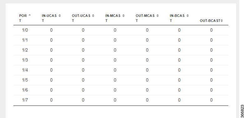
You can view the Switch Interface operational data and the statistics parameters in the following table:

Table 1. Switch Settings Interface

Parameter

Description

Values

SwitchPort

Specifies the switch interface name.

Description

Specifies the description of the interface.

Status

Specifies the status of the interface.

up or down

MAC Address

Specifies the MAC address of the interface.

PortType

Specifies the mode of the port interface.

Supported types are:

  • access

  • dot1q-tunnel

  • private-vlan

  • trunk

VLAN

Specifies the VLAN ID.

Range: 1-2349 and 2450-4093

Speed

Specifies the speed of the interface.

Speed:

  • 10 MBPS

  • 100 MBPS

  • 1000 MBPS

RxBytes

Specifies the received data on interface in bytes.

PktDrop

Specifies the number of packet drops.

PORT

Specifies the port number.

IN-UCAST

Specifies the number of incoming unicast packets at the interface.

OUT-UCAST

Specifies the number of outgoing unicast packets at the interface.

IN-MCAST

Specifies the number of incoming multicast packets at the interface.

OUT-MCAST

Specifies the number of outgoing multicast packets at the interface.

IN-BCAST

Specifies the number of incoming broadcast packets at the interface.

OUT-BCAST

Specifies the number of outgoing broadcast packets at the interface.

Configuring Spanning Tree

Spanning Tree Protocol (STP) is a Layer 2 protocol that runs on bridges and switches. The main purpose of STP is to ensure that you do not create loops when you have redundant paths in your network.

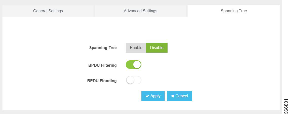
The Spanning Tree option is enabled by default. You can click on edit and make the necessary settings or disable Spanning Tree if required.
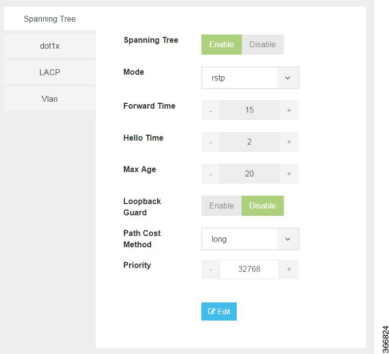
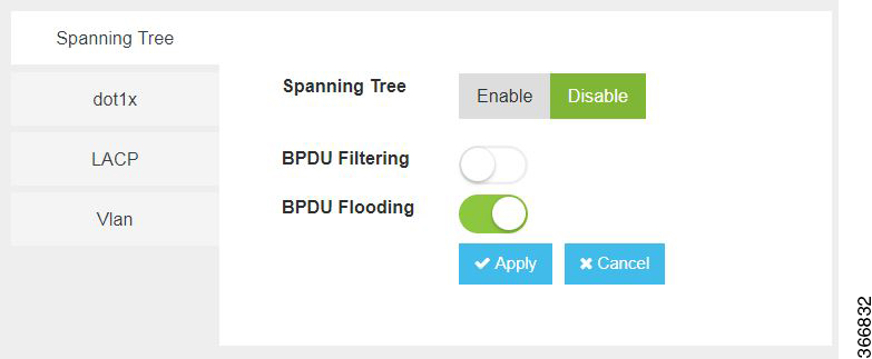
The configuration of spanning tree has the following parameters when it is enabled:

Table 2. Spanning Tree Parameters

Parameter

Description

Values

Spanning Tree

Specifies the state of the Spanning Tree.

Enable or Disable

The default value is Enable.

Mode

Specifies the mode of the Spanning Tree.

stp or rstp

Forward Time

Specifies the Spanning Tree forward time in seconds.

Range: 4-30 seconds

Hello Time

Specifies the Hello time in seconds.

Range: 1 to10 seconds

Max Age

Specifies the spanning-tree bridge maximum age in seconds.

Range: 6 to 40 seconds

Loopback Guard

Specifies the loopback guard status.

Enable or Disable

Path Cost Method

Specifies the speed of the interface.

Method:

  • long - for 32 bit based values for default port path costs.

  • short - 16 bit based values for default port path costs.

The default method is long.

Priority

Specifies the port priority.

Range: 0 to 61440 in steps of 4096

The default value is 32768.

BPDU Filtering

Specifies that BPDU packets are filtered when the spanning tree is disabled on an interface.

BPDU Flooding

Specifies that BPDU packets are flooded unconditionally when the spanning tree is disabled on an interface.

Configuring Dot1x

This chapter describes how to configure dot1x port-based authentication on the Cisco Enterprise NFVIS portal. dot1x prevents unauthorized devices (clients) from gaining access to the network. It is a standard for media-level (Layer 2) access control, offering the capability to permit or deny network connectivity based on the identity of the end user or device. The dot1x is disabled by default. You can click on edit to enable dot1x.
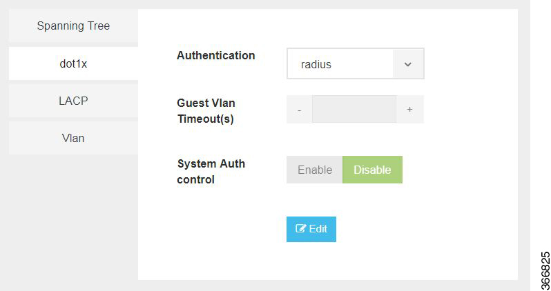
The configuration of dot1x has the following parameters:

Table 3. Dot1x Parameters

Parameter

Description

Values

Authentication

Specifies the authentication type for the port.

radius or none

The default value is radius.

Guest VLAN Timeout(s)

Specifies the time delay in seconds between enabling Dot1X (or port up) and adding the port to the guest VLAN.

Range: 30 to 180 seconds

System Auth control

Specifies the authentication control.

Enable or Disable

Configuring LACP

The Link Aggregation Control Protocol (LACP) enables you to bundle several physical ports together to form a single logical channel. LACP enables you to form a single Layer 2 link automatically from two or more Ethernet links. This protocol ensures that both ends of the Ethernet link are functional and are part of the aggregation group.
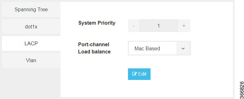
LACP uses the following parameters to control aggregation:

Table 4. LACP Parameters

Parameter

Description

Values

System Priority

Specifies the port priority.

Range: 1 to 65535

Port-channel load balance

Specifies the load balance of the port channel.

Mac Based or IP Based

Configuring VLAN

You can use virtual LANs (VLANs) to divide the network into separate logical areas. VLANs can also be considered as broadcast domains. Any switch port can belong to a VLAN, and unicast, broadcast, and multicast packets are forwarded and flooded only to end stations in that VLAN. Each VLAN is considered a logical network, and packets destined for stations that do not belong to the VLAN must be forwarded through a router.

You can configure VLANs in the range <1-2349>|<2450-4093> for a specified switch port.
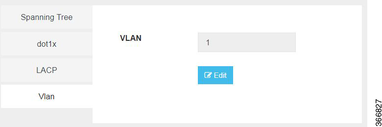
Configuring General Settings
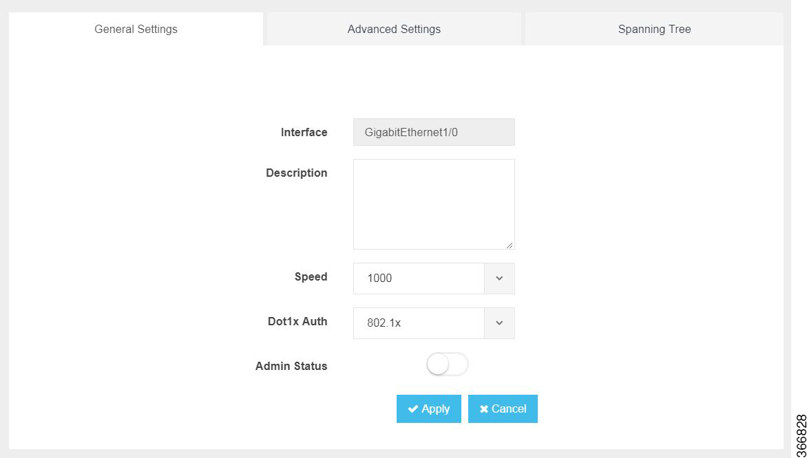
You can configure general settings using the following parameters for each switch interface:

  • Interface—Name of the interface

  • Description—Set the description per interface

  • Speed—10/100/1000 MBPS

  • Dot1x Auth—802.1x, mac or both

  • PoE Method—auto, never or four-pair

  • PoE Limit—0-60000mW

  • Admin Status—enable or disable

Configuring Advanced Settings
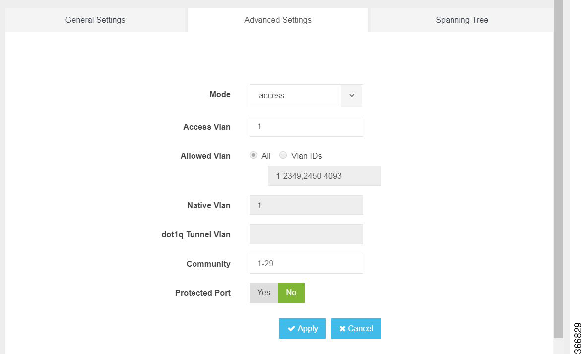
You can make the advanced settings using the following parameters for each switch interface:

  • Mode—access, dot1q-tunnel, private-vlan, or trunk

  • Access Vlan—Specifies the number of VLANs.

  • Allowed Vlan—All or VLAN IDs

  • Native Vlan—Specifies the VLAN ID. You can enter a value from one of the following ranges:

    • 1 to 2349

    • 2450 to 4093

  • Dot1q Tunnel Vlan—Specifies the Layer 2 tunnel port.

  • Community—Specifies the community number. Range: 1 to 29

  • Protected Port—Yes or No


Note

The VLAN configuration takes effect only if the global VLANs are also configured with the same values in Configuring VLAN.


Configuring Spanning Tree per Interface
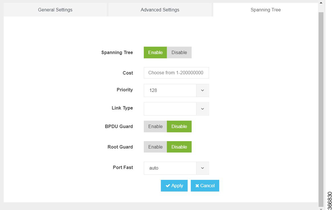
You can configure spanning tree for each switch interface using the following parameters:

  • Spanning Tree—Enable or Disable

  • Cost—Specifies the cost. Range: 1 to 200000000

  • Priority—Specifies the port priority. Range: 0 to 240, default value is 128

  • Link Type—point-to-point or shared

  • BPDU Guard—Enable or Disable

  • Root Guard—Enable or Disable

  • Port Fast—auto or enable

  • BPDU Filtering—Specifies that BPDU packets are filtered when the spanning tree is disabled

  • BPDU Flooding—Specifies that BPDU packets are flooded when the spanning tree is disabled

Configuring Storm Control

Storm control is used to monitor incoming traffic levels and limit excessive flow of packets on any user facing switch port that could cause a traffic storm. Traffic storms can lead to device instability and unintended behavior.

You can configure storm control from NFVIS Portal, from Storm Control tab.
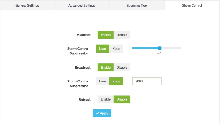
Storm control can be configured for specific type of traffic - unicast or multicast or broadcast. The suppression range can be in terms of a percentage level (1-100) or Kbps value (1-1000000).
Configuring vBranch High Availability

High availability design provides redundancy for WAN, LAN, ENCS device, vRouter, vFirewall VNF level redundancy.

A branch site can have two routers for redundancy. If vEdge-cloud router is chosen, Each of the vedge-cloud router maintains:

  • A secure control plane connection, via a DTLS connection, with each vSmart controller in its domain

  • A secure data plane connection with the other vEdge routers at the site

Because both vEdge routers receive the same routing information from the vSmart controllers, each one is able to continue to route traffic if one should fail, even if they are connected to different transport providers.

Two firewalls are placed in a group and their configuration is synchronized to prevent a single point of failure on your network. A heartbeat connection between the firewall peers ensures seamless failover in the event that a peer goes down. Setting up two firewalls in an HA pair provides redundancy and allows you to ensure business continuity.

Prerequisites for vBranch HA

The WAN links are active on both Cisco ENCS1 and Cisco ENCS2. Each of the ENCS WAN link is connected to the WAN network (most cases with two SPs), with two ENCSs in an active-active mode.

The LAN facing links of both Cisco ENCS devices are connected to an external switch (as an uplink), and all the devices on the LAN segment are also connected to the external switch. There should be no LAN device connecting directly to the Cisco ENCS internal switch.

Two vRouters and the Two vFirewalls have full mesh L3 connectivity.

VMs and VNFs on both ENCS devices must be configured identical.

SD-Branch HA Design and Topology

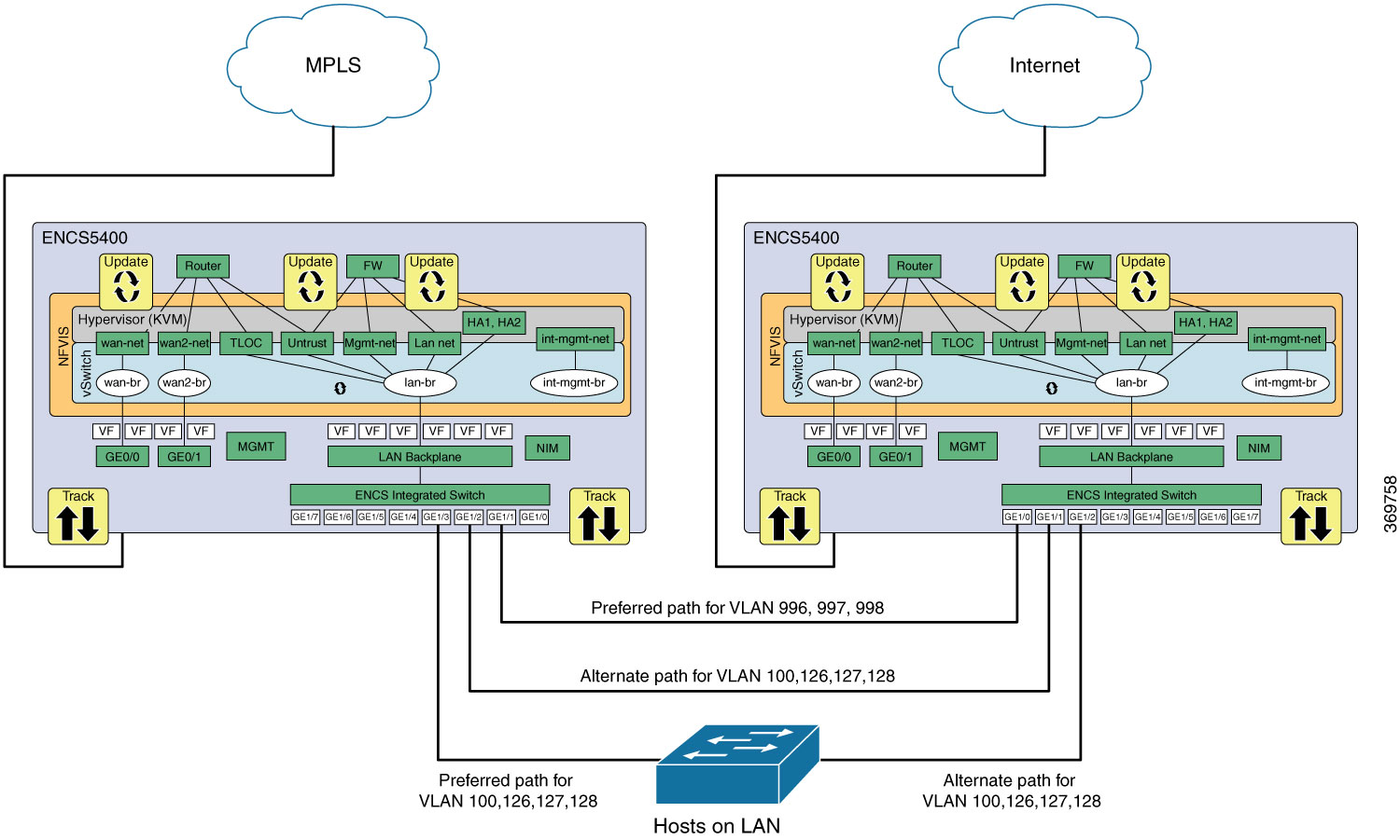
In HA design, there are two sets of VLANs. Traffic path is between the VNFs and traffic from or towards LAN.

To protect against cable connection issue and box failure, there is back-to-back cable between ENCS and connection from each ENCS to the external switch.

When using Cisco ENCS and Cisco switches, common expectation is to use PVST+, detect loops and switch specific ports to BLOCKING mode. ENCS switch does not support PVST (Per VLAN spanning tree). By Default, RSTP could end up blocking ENCS port back-to-back connection, this will result in blocking traffic path between the VNFs.

The recommended solution is to use MSTP in ENCS and the external switches. The following topology and configuration provides a step-by-step procedure with reasoning for specific configuration use. There are two instances of MSTP created. One for handling traffic path between VNFs and the second for handling traffic from or towards LAN.


Note

In cases where external switch cannot be configured for MSTP, RSTP is used and the two links back-2-back between ENCS is not in port-channel.

  • One of the links carries traffic between VNFs by configuring disable spanning tree. The second back-to-back link between ENCS processes RSTP and forward or block for the traffic from or towards LAN.

  • From each of the ENCS, a third physical link connects to the external switch. This also forwards or blocks the traffic from or towards LAN depending on the RSTP decisions.


Physical Device Connections

VM and Service Chain Network Connection

Figure 1. ENCS-Left
Figure 2. ENCS-Right

Note

In the absence of firewall in the design, the router is directly connected to the LAN side. Pt-to-Pt network extends the TLOC connection across the ENCS devices and VRRP is enabled in the router LAN facing connection.


Isolating LAN and Transit Link Traffic for vBranch HA

Traffic from or towards LAN and traffic between the VNFs are isolated by configuring different VLANs for each traffic since both links are connected to the same ENCS internal switch. If you do not isolate the traffic, both LAN traffic and transit link will flow through the same internal switch on the Cisco ENCS.

Enable Port Tracking and Virtual NIC Update

The configured VNICs tracks the state of the ports based on the PNICs notifications. To verify the state of the port, use show interface or ethtool commands. You can also use commands specific to the VM, that displays the interface link state.

To configure track state on GE0-0 & GE0-1:


configure terminal
pnic GE0-0 track-state ROUTER 1
end

ENCS-Left# support show ifconfig GE0-0

GE0-0: flags=4611<UP,BROADCAST,ALLMULTI,MULTICAST>  mtu 9216
        ether 70:db:98:c3:df:28  txqueuelen 1000  (Ethernet)

To configure track state on switch port:


configure terminal
switch interface gigabitEthernet 1/3 track-state FIREWALL 4
end

ENCS-Left# show vm_lifecycle deployments FIREWALL


Name: FIREWALL
Deployment Name : FIREWALL
VM Group Name : FIREWALL
State: ALIVE
Internal State: VM_INERT_STATE
Bootup Time: -1
Image: Palo-Alto-8.1.3.tar.gz
Flavor: VM-100


VCPU#  Memory(MB)  Disk(MB)
----------------------------
2      7168        61440


Low Latency: true
VCPU  CPU  CORE  SOCKET
-----------------------
0     3      3     0
1     2      2     0


NICID  VNIC   NETWORK  IP   MAC-ADDRESS        MODEL    PORT-FORWARD
-----------------------------------------------------------------------------
0      vnic6  mgmt-net -    52:54:00:2b:72:d2  virtio
1      vnic7  Untrust  -    52:54:00:eb:a3:e7  virtio
2      vnic8  HA1      -    52:54:00:f4:de:e5  virtio
3      vnic9  HA2      -    52:54:00:12:f8:21  virtio
4      vnic10  Trust    -    52:54:00:7a:6b:e9  virtio


ENCS-Left# support show ifconfig vnic10

vnic10: flags=4163<UP,BROADCAST,RUNNING,MULTICAST>  mtu 9216
        inet6 fe80::fc54:ff:fe7a:6be9  prefixlen 64  scopeid 0x20<link>
        ether fe:54:00:7a:6b:e9  txqueuelen 4000  (Ethernet)

Packet Flow for SD-Branch HA

This section explains high-level packet flow in non-failure and failure cases.

Non-Failure Case

In the non-failure case, both ENCS devices are Active, up and running

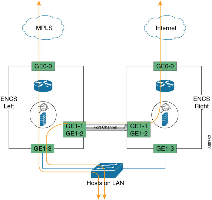
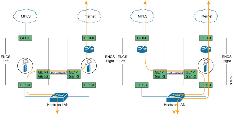
  • LAN to WAN through the ENCS1 Firewall and ENCS1 Router

  • LAN to WAN through the ENCS1 Firewall and ENCS2 Router

  • WAN to LAN through ENCS1 Router and ENCS1 Firewall

  • WAN to LAN through ENCS2 Router and ENCS1 Firewall

Failure Case

Following are failures that a router must be designed and configured to adapt

The conditions that trigger a firewall failover are:

  • One or more of the monitored interfaces fail. (Link Monitoring)

  • One or more of the destinations specified on the firewall cannot be reached. (Path Monitoring)

  • The firewall does not respond to heartbeat polls. (Heartbeat Polling and Hello messages)

Configuration Examples and Usage Description

ENCS-Left and ENCS-Right with Same Config

Description or Reasons for configuration


networks network wan-net
 bridge wan-br
!
networks network HA1
 vlan   [ 126 ]
 trunk  false
 bridge lan-br
!
networks network HA2
 vlan   [ 127 ]
 trunk  false
 bridge lan-br
!
networks network Trust
 vlan   [ 128 ]
 bridge lan-br
!
networks network Untrust
 vlan   [ 998 ]
 bridge lan-br
!
networks network mgmt-net
 vlan   [ 100 ]
 trunk  false
 bridge lan-br
!
networks network pt-2-pt
 vlan   [ 996 997 ]
 bridge lan-br

In a HA design involving a router or Firewall, there are 3 to 6 paths required. ENCS platform has 2 WAN facing ports and 8 LAN facing ports.

  • WAN facing ports are reserved for connection to WAN circuits.

  • LAN facing ports are the only set of available ports for creating the 3 to 6 path required.

Between VNFs and LAN, OVS or SR-IOV VFs and physical switch ports are the two Layer2 entities to traverse.


!
 vlan 1
!
 vlan 100
 !
 vlan 126
 !
 vlan 127
 !
 vlan 128
 !
 vlan 996
 !
 vlan 997
 !
 vlan 998
 !
 spanning-tree enable
 spanning-tree mode mst
 spanning-tree mst 2 priority 61440
 spanning-tree mst configuration
  name mst_LAN
  instance 1 vlan 996-998
  instance 2 vlan 100,126-128
!

VLAN must be explicitly created before they are used in the interfaces.

Enable MSTP. For MST group 2 carrying “Traffic towards/from LAN”, force the External Switch to become the ROOT using the “mst <group> priority <value>” CLI. The Higher the value, lower the chance of becoming spanning-tree ROOT.

“priority” configuration is NOT required for the MST group 1 carrying “Traffic between VNFs”. There is NO loop possibility for MST group 1 VLANs.


nfvis# show running-config switch
switch
interface gigabitEthernet1/1
  no shutdown
  channel-group 1 mode auto
 !
 interface gigabitEthernet1/2
  no shutdown
  channel-group 1 mode auto
!
switch
 interface port-channel1
  negotiation auto
  no shutdown
  spanning-tree mst 1 cost 200000000
  spanning-tree mst 2 cost 200000000
  switchport mode trunk
  switchport trunk native vlan 1
  switchport trunk allowed vlan 100,126-128,996-998
 !

For the back-to-back ENCS connection, link redundancy is achieved using port-channel configuration. Interfaces that are belong to a port-channel group use configuration from “interface port-channel x”

Goal is to prefer the direct links from ENCS to the External Switch for “Traffic towards/from LAN”. In ENCS back-to-back connection, Spanning tree cost is HIGH for MST group carrying “Traffic towards/from LAN”. This config will block one of the ENCS back-to-back interfaces for breaking the loop for MST group carrying “Traffic towards/from LAN”.

Status of MST instances.

For MST instance 1, “Traffic between the VNFs”, back-to-back portchannel link is root and forwading state.

For MST instance 2, “Traffic from/towards the LAN”, links connected to External Switch are in forwarding state, path via back-to-back portchannel link is “Blocking state”. If one of the Links fail between ENCS and External switch, portchannel path for MST instance 2 will be unblocked.


ENCS-Left# show switch vlan detailed

VLAN              TAGGED
ID    VLAN  NAME  PORTS        UNTAGGED PORTS       CREATED BY
-----------------------------------------------------------------------
1     1     1     None         gi0,gi4-6,te2,po2-4   DefaultVoiceVLAN
100   100   100   gi3,te2,po1  gi7                   Manual
126   126   126   gi3,te2,po1  None                  Manual
127   127   127   gi3,te2,po1  None                  Manual
128   128   128   gi3,te2,po1  None                  Manual
996   996   996   te2,po1      None                  Manual
997   997   997   te2,po1      None                  Manual
998   998   998   te2,po1      None                  Manual

ENCS-Left# show switch spanning-tree mstp summary

spanning-tree mstp summary ist-info summary admin-status enabled
spanning-tree mstp summary ist-info summary Operation-mode MSTP
spanning-tree mstp summary ist-info summary Port-Cost-Method long
spanning-tree mstp summary ist-info summary Loopback-guard disabled
spanning-tree mstp summary ist-info root Priority 32768
spanning-tree mstp summary ist-info root Address 70:db:98:c3:df:14
spanning-tree mstp summary ist-info root Cost 0
spanning-tree mstp summary ist-info root Port LAG1
spanning-tree mstp summary ist-info root Hello-Time 2
spanning-tree mstp summary ist-info root Max-Age 20
spanning-tree mstp summary ist-info root Forward-Delay 15
spanning-tree mstp summary ist-info bridge Priority 32768
spanning-tree mstp summary ist-info bridge Address 70:db:98:c3:df:a0
spanning-tree mstp summary ist-info bridge Hello-Time 2
spanning-tree mstp summary ist-info bridge Max-Age 20
spanning-tree mstp summary ist-info bridge Forward-Delay 15
spanning-tree mstp summary ist-info 
…..
…..

INSTANCE  PRIORITY  DSG ROOT ADDRESS   BRIDGE ADDRESS
----------------------------------------------------------
1         32768     70:db:98:c3:df:14  70:db:98:c3:df:a0
2         61440     f0:b2:e5:56:e4:80  70:db:98:c3:df:a0

INST                  PRIO.
ID    PORT   STATE    NBR    COST     STS         ROLE
--------------------------------------------------------------
1     gi1/0  enabled  128.1  2000000  disabled    disabled
1     gi1/3  enabled  128.4  20000    forwarding  designated
1     gi1/4  enabled  128.5  2000000  disabled    disabled
1     gi1/5  enabled  128.6  2000000  disabled    disabled
1     gi1/6  enabled  128.7  2000000  disabled    disabled
1     gi1/7  enabled  128.8  2000000  disabled    disabled
2     gi1/0  enabled  128.1  2000000  disabled    disabled
2     gi1/3  enabled  128.4  20000    forwarding  root
2     gi1/4  enabled  128.5  2000000  disabled    disabled
2     gi1/5  enabled  128.6  2000000  disabled    disabled
2     gi1/6  enabled  128.7  2000000  disabled    disabled
2     gi1/7  enabled  128.8  2000000  disabled    disabled
INST                 PRIO.
ID    PORT  STATE    NBR       COST       STS         ROLE
-----------------------------------------------------------------
1     po1   enabled  128.1000  10000      forwarding  root
1     po2   enabled  128.1001  2000000    disabled    disabled
1     po3   enabled  128.1002  2000000    disabled    disabled
1     po4   enabled  128.1003  2000000    disabled    disabled
2     po1   enabled  128.1000  200000000  blocking    alternate
2     po2   enabled  128.1001  2000000    disabled    disabled
2     po3   enabled  128.1002  2000000    disabled    disabled
2     po4   enabled  128.1003  2000000    disabled    disabled

ENCS-Left#

ENCS-Right# show switch vlan detail

VLAN              TAGGED
ID    VLAN  NAME  PORTS        UNTAGGED PORTS       CREATED BY
-----------------------------------------------------------------------
1     1     1     None         gi0,gi4-6,te2,po2-4   DefaultVoiceVLAN
100   100   100   gi3,te2,po1  gi7                   Manual
126   126   126   gi3,te2,po1  None                  Manual
127   127   127   gi3,te2,po1  None                  Manual
128   128   128   gi3,te2,po1  None                  Manual
996   996   996   te2,po1      None                  Manual
997   997   997   te2,po1      None                  Manual
998   998   998   te2,po1      None                  Manual

ENCS-Right# show switch spanning-tree mstp summary

spanning-tree mstp summary ist-info summary admin-status enabled
spanning-tree mstp summary ist-info summary Operation-mode MSTP
spanning-tree mstp summary ist-info summary Port-Cost-Method long
spanning-tree mstp summary ist-info summary Loopback-guard disabled
spanning-tree mstp summary ist-info root Priority 32768
spanning-tree mstp summary ist-info root Address 70:db:98:c3:df:14
spanning-tree mstp summary ist-info root Cost 0
spanning-tree mstp summary ist-info root Port 0
spanning-tree mstp summary ist-info root Hello-Time 2
spanning-tree mstp summary ist-info root Max-Age 20
spanning-tree mstp summary ist-info root Forward-Delay 15
spanning-tree mstp summary ist-info bridge Priority 32768
spanning-tree mstp summary ist-info bridge Address 70:db:98:c3:df:14
spanning-tree mstp summary ist-info bridge Hello-Time 2
spanning-tree mstp summary ist-info bridge Max-Age 20
spanning-tree mstp summary ist-info bridge Forward-Delay 15
spanning-tree mstp summary ist-info 
……
……

INSTANCE  PRIORITY  DSG ROOT ADDRESS   BRIDGE ADDRESS
----------------------------------------------------------
1         32768     70:db:98:c3:df:14  70:db:98:c3:df:14
2         61440     f0:b2:e5:56:e4:80  70:db:98:c3:df:14

INST                  PRIO.
ID    PORT   STATE    NBR    COST     STS         ROLE
--------------------------------------------------------------
1     gi1/0  enabled  128.1  2000000  disabled    disabled
1     gi1/3  enabled  128.4  20000    forwarding  designated
1     gi1/4  enabled  128.5  2000000  disabled    disabled
1     gi1/5  enabled  128.6  2000000  disabled    disabled
1     gi1/6  enabled  128.7  2000000  disabled    disabled
1     gi1/7  enabled  128.8  2000000  disabled    disabled
2     gi1/0  enabled  128.1  2000000  disabled    disabled
2     gi1/3  enabled  128.4  20000    forwarding  root
2     gi1/4  enabled  128.5  2000000  disabled    disabled
2     gi1/5  enabled  128.6  2000000  disabled    disabled
2     gi1/6  enabled  128.7  2000000  disabled    disabled
2     gi1/7  enabled  128.8  2000000  disabled    disabled

INST                 PRIO.
ID    PORT  STATE    NBR       COST       STS         ROLE
------------------------------------------------------------------
1     po1   enabled  128.1000  10000      forwarding  designated
1     po2   enabled  128.1001  2000000    disabled    disabled
1     po3   enabled  128.1002  2000000    disabled    disabled
1     po4   enabled  128.1003  2000000    disabled    disabled
2     po1   enabled  128.1000  200000000  forwarding  designated
2     po2   enabled  128.1001  2000000    disabled    disabled
2     po3   enabled  128.1002  2000000    disabled    disabled
2     po4   enabled  128.1003  2000000    disabled    disabled
ENCS-Right#

From the above summary output, MST instances indicates ID and associated VLAN, and then displays all interfaces as part of VLAN instances. This behaviour differs from the way MST instances are displayed on other Cisco switching platforms.

External Switch MST Configuration


Note

It is recommended that VLAN 996-998 is not allowed through the interfaces connecting to ENCS-Left and ENCS-Right. As a result, the external switch MSTP does not participate for VLAN 996-998.


Table 5.

vlan 100,126-128
!
spanning-tree mode mst
spanning-tree extend system-id
spanning-tree uplinkfast
!
spanning-tree mst configuration
 name mst_LAN
 instance 1 vlan 996-998
 instance 2 vlan 100, 126-128
!
interface GigabitEthernet1/0/1
 switchport trunk allowed vlan 100,126-128
 switchport mode trunk
!
interface GigabitEthernet1/0/2
 switchport trunk allowed vlan 100,126-128
 switchport mode trunk

VLANs carrying “Traffic between the VNFs” are NOT sent to the External Switch.

MST instance priority and MST link COST are kept default in the External Switch.

MST Priority and COST Configuration in ENCS ensure the External switch is the root and the Interfaces in the External switch connecting to ENCS are in Forwarding state.


Note

VLANs carrying traffic between VNFs are not used in external switch and not configured in any interface.


Switch#show spanning-tree mst detail

##### MST0    vlans mapped:   1-99,101-125,129-995,999-4094   
Bridge        address f0b2.e556.e480  priority      32768 (32768 sysid 0)
Root          address 70db.98c3.df14  priority      32768 (32768 sysid 0)
              port    Gi1/0/2         path cost     0        
Regional Root address 70db.98c3.df14  priority      32768 (32768 sysid 0)
                                      internal cost 20000     rem hops 19
Operational   hello time 2 , forward delay 15, max age 20, txholdcount 6 
Configured    hello time 2 , forward delay 15, max age 20, max hops    20

GigabitEthernet1/0/1 of MST0 is alternate blocking 
Port info             port id          128.1  priority    128  cost       20000
Designated root       address 70db.98c3.df14  priority  32768  cost           0
Design. regional root address 70db.98c3.df14  priority  32768  cost       10000
Designated bridge     address 70db.98c3.dfa0  priority  32768  port id    128.4
Timers: message expires in 5 sec, forward delay 0, forward transitions 0
Bpdus sent 27905, received 31061

GigabitEthernet1/0/2 of MST0 is root forwarding 
Port info             port id          128.2  priority    128  cost       20000
Designated root       address 70db.98c3.df14  priority  32768  cost           0
Design. regional root address 70db.98c3.df14  priority  32768  cost           0
Designated bridge     address 70db.98c3.df14  priority  32768  port id    128.4
Timers: message expires in 5 sec, forward delay 0, forward transitions 1
Bpdus sent 27904, received 31070

##### MST2    vlans mapped:   100,126-128
Bridge        address f0b2.e556.e480  priority      32770 (32768 sysid 2)
Root          this switch for MST2

GigabitEthernet1/0/1 of MST2 is designated forwarding 
Port info             port id          128.1  priority    128  cost       20000
Designated root       address f0b2.e556.e480  priority  32770  cost           0
Designated bridge     address f0b2.e556.e480  priority  32770  port id    128.1
Timers: message expires in 0 sec, forward delay 0, forward transitions 1
Bpdus (MRecords) sent 27905, received 31061

GigabitEthernet1/0/2 of MST2 is designated forwarding 
Port info             port id          128.2  priority    128  cost       20000
Designated root       address f0b2.e556.e480  priority  32770  cost           0
Designated bridge     address f0b2.e556.e480  priority  32770  port id    128.2
Timers: message expires in 0 sec, forward delay 0, forward transitions 1
Bpdus (MRecords) sent 27904, received 31070

Switch#