The documentation set for this product strives to use bias-free language. For the purposes of this documentation set, bias-free is defined as language that does not imply discrimination based on age, disability, gender, racial identity, ethnic identity, sexual orientation, socioeconomic status, and intersectionality. Exceptions may be present in the documentation due to language that is hardcoded in the user interfaces of the product software, language used based on RFP documentation, or language that is used by a referenced third-party product. Learn more about how Cisco is using Inclusive Language.
Installing the Cisco
NCS 2015 Door and Other Modules
This chapter
describes how to install the NCS 2015 door and other modules.
The sections are:
Front Door
The front door of NCS
2015 provides access to the shelf, fiber-routing tray, fan-tray assembly, and
LCD screen.
There are two types
of front doors that act as protective panels—standard door and deep door. The
deep door provides additional space in front of the shelf to accommodate cables
that do not fit inside the standard door. The deep door has a hinge and can be
rotated like the standard door.
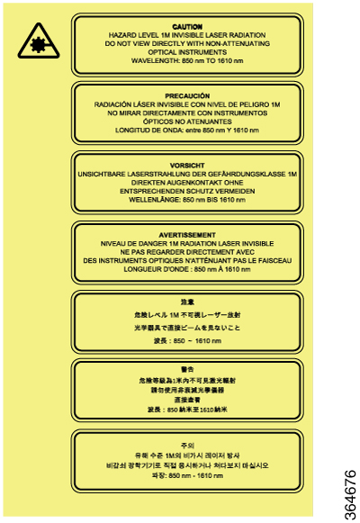
The laser warning
label is placed on the rear of the chassis.
The following figure
shows the NCS 2015 laser warning.
Figure 1. Laser Warning on the NCS 2015
NTP-L67 Installing
Fiber Tray of NCS 2015 Shelf
Purpose
This
procedure installs the standard or extended fiber tray of the NCS 2015 shelf.
Tools/Equipment
#2
Phillips Dynamometric screwdriver
PrerequisiteProcedures
None
Required/AsNeeded
As needed
Onsite/Remote
Onsite
SecurityLevel
None
Note
The standard
fiber tray is included in the standard door PID and the extended fiber tray is
included in the deep door PID.
Procedure
Step 1
Align the fiber
tray screw holes against the shelf screw holes.
Step 2
Insert the M3
x 10 mm screws (one screw on each side and tighten them to a torque value of
11.5 in-lb (1.3 N-m). See figures below.
Step 3
Insert the M3
x 8mm screws (two screws on the bottom of the fiber tray) and tighten them to a
torque value of 11.5 in-lb (1.3 N-m). See figures below.
Figure 2. Installing the Standard Fiber Tray
1
M3 x10 mm screws
2
M3 x8 mm screws
3
Standard fiber tray
Figure 3. Installing the Extended Fiber Tray
1
M3 x10 mm screws
2
M3 x8 mm screws
3
Extended fiber tray
The installed
fiber tray is shown in the figures below.
Figure 4. Installed Standard Fiber Tray
1
Standard fiber tray
Figure 5. Installed Extended Fiber Tray
1
Extended fiber tray
Stop. You have completed this procedure.
NTP-L50 Installing
Standard Door of NCS 2015 Shelf
Purpose
This
procedure installs the standard door of the NCS 2015 shelf.
Align the left
deep door bracket screw holes against the shelf screw holes.
Step 2
Insert the M3 x
10 mm screws (three screws on the side and two screws on the bottom of the deep
door bracket) and tighten them to a torque value of 11.5 in-lb (1.3 N-m). (See
the figures below.)
Step 3
Place a safety
washer on the front bottom of the deep door bracket and fasten it with a M3 x 8
mm screw. (See the figures below.)
Step 4
Repeat steps 1
and 2 for the deep door bracket on the opposite side. (See the figures below.)
Figure 10. Installing
the Deep Door Bracket of NCS 2015 DC Shelf
1
Deep
door bracket
2
M3 x
8 mm screw
3
Safety washer
4
M3 x
10 mm screw
Figure 11. Installing the Deep Door Bracket of NCS 2015 AC
Shelf
1
Deep door bracket
2
M3
x 8 mm screw
3
Safety washer
4
M3
x 10 mm screw
Step 5
Pull the top
hinge pin down on the deep door. (See the figures below.)
Note
The bottom
hinge pin is fixed.
Step 6
Align the
deep door hinges with the bracket hinges. (See the figures below.)
Step 7
Slide the
bottom hinge pin into the bracket hinge and move the top hinge pin in the
upward direction.
Note
The ground
strap cable is pre-installed on the deep door. (See the figures below.)
Figure 12. Installing the Deep Door and Ground Strap Cable to the NCS
2015 DC Shelf
1
Deep door
2
M3 x 6 mm screw
Figure 13. Installing the Deep Door and Ground Strap Cable to the NCS
2015 AC Shelf
1
Deep door
2
M3 x 6 mm screw
Step 8
Connect the
other end of the ground strap cable to a grounding point on the deep door
bracket using a M3 x 6 mm screw. (See the figure below.)
Figure 14. Ground
Strap Cable
1
Ground strap cable
Step 9
Swing the
door closed and turn the knob to lock. (See the figures below.)
Figure 15. Installed Deep Door in NCS 2015 DC Shelf
1
Deep door
Figure 16. Installed Deep Door in NCS 2015 AC Shelf
1
Deep door
Stop. You have completed this procedure.
NTP-L51 Opening and
Removing the Door of the NCS 2015 Shelf
Purpose
This
procedure opens and removes the door of the NCS 2015 shelf.
The NCS 2015
shelf has an ESD plug input and is shipped with an ESD wrist strap. The ESD
plug input is located on the outside of the shelf on the right side. It is
labeled “ESD” on the top and bottom. Always wear an ESD wrist strap and connect
the strap to the ESD plug when working on the NCS shelf. For detailed
instructions on how to wear the ESD wristband, see the
Electrostatic Discharge and Grounding Guide for
Cisco NCS 2000 Series .
Procedure
Step 1
Turn the knob
to unlock the door.
Step 2
Swing the door
open.
Step 3
Remove the
ground cable from the shelf by removing the screw.
Step 4
Pull the top
hinge pin holding the door to the chassis, in the downward direction.
Step 5
Lift the door
out of the bottom hinge pin to remove the door from its hinges.
Stop.
You have completed this procedure.
External Connection
Units
The NCS 2015 external
connection unit (ECU) is a replaceable module that provides interfaces for
passive device inventory and management, multishelf management, and element
management. The ECU module available for the NCS 2015 shelf is NCS2015-ECU and
is installed in slot 18 of the NCS 2015 shelf.
The ECU contains
RJ-45 and SFP interfaces or multishelf and element management. Fourteen USB
ports connect to passive devices, two of which are USB 3.0 ports. A backup
flash memory is fitted into the ECU to support the database (DB) and image
backup in the operation of the NCS 2015.
The ECU contains two LEDs that indicate the link and activity status of
the optical EMS SFP port.
Table 1. ECU LED Status Indicator Lights
LED Name
Color
Description
Link Speed
Green
The LED is on when there is a link connection; otherwise, the
LED is off.
Activity
Yellow
The LED is flashing when there is activity on the link;
otherwise, the LED is off.
The following figure
shows the NCS 2015 ECU connectors.
Figure 17. Connectors on
the NCS 2015 ECU Faceplate
1
USB 2.0
ports (Ports 1 through 12)
2
USB 3.0
ports (Ports 13 and 14)
3
VOIP/UDC
ports ( RJ-45 port)
4
MSM port (
RJ-45 port)
5
EMS port
(SFP port)
6
MSM ports
(SFP ports)
The following table
lists the external connections present on the NCS 2015 ECU :
The ECU cannot be
pre-provisioned in CTC. After the ECU is physically plugged into Slot 18 of the
NCS 2015 shelf, the unit is detected by CTC and all the entities of the ECU
such as the USB ports, RJ-45 ports, and the optical pluggable ports are created
in CTC. In the ECU card view in CTC, only the pluggable ports are visible. The
ECU card view displays the Alarms, Conditions, History, Provisioning and
Maintenance sub-tabs. All the values in these sub-tabs, except for the port
name, are display only. Performance monitoring is not supported on the
pluggable FE ports of the ECU. The MS-ISC (RJ-45) ports are displayed in the
CTC ECU card view > Provisioning > Alarm Profiles > Alarm Behavior
tab. The IMPROPRMVL alarm is raised in CTC when the ECU is removed from the NCS
2015 shelf. The ECU entities and the ECU card view in CTC remain as they are,
even though the ECU has been removed from the NCS 2015 shelf. The ECU cannot be
deleted in CTC.
The Fiber Shuffle or
the CDC fan out unit can be connected to the NCS 2015 ECU using the USB 3.0
port.
Passive Unit Inventory Interfaces
The passive unit inventory interfaces (USB ports) are used to retrieve inventory information from passive devices such as
fiber trays, FBG DCU, patch panels, passive multiplexer or demultiplexer, and so on. There are 14 USB (12 USB 2.0 ports and
two USB 3.0 ports.) ports on the NCS 2015 ECU. The inventory details are displayed in the Inventory tab in CTC.
MSM
The multishelf management (MSM) port is an RJ-45 or SFP port that is used to connect the NCS 2015 shelf to other NCS 2015
or NCS 2015 shelves that are a part of the multishelf configuration. There are six MSM ports on the NCS 2015 ECU module.
Three MSM ports (one RJ-45 port and two SFP ports) are prefixed with M and correspond to the TNCS card in Slot 1. The other
three MSM ports (one RJ-45 port and two SFP ports) are prefixed with P and correspond to the TNCS card in slot 17. The SFP
modules must be plugged in for using the optical MSM ports. MSM connections between the NC and SSC can be done using RJ-45
ports, SFP ports, or both. The MSM cable connections can be created between two M-MSM-x ports or two P-MSM-x ports.
VoIP or UDC
VoIP or UDC is an RJ45 port that can be configured to support UDC or VoIP service on an NCS 2015 shelf. There are two VoIP
or UDC ports on the NCS 2015 ECU module. The UDC/VoIP-1 port is connected to the TNCS card in Slot 1 and the UDC/VoIP-2 port
is connected to the TNCS card in Slot 17. The VoIP or UDC port also supports Power over Ethernet for connecting VoIP equipments.
NTP-L52 Install NCS
2015 ECU Module
Purpose
This
procedure installs the external connection unit (ECU) in the NCS 2015 shelf.
The
intra-building port(s) of the equipment or subassembly is suitable for
connection to intra-building or unexposed wiring or cabling only. The
intra-building port(s) of the equipment or subassembly MUST NOT metallically
connect to interfaces that connect to the OSP or its wiring. These interfaces
are designed for use as intra-building interfaces only (Type 2 or Type 4 ports
as described in GR-1089-CORE, Issue 5) and require isolation from the exposed
OSP cabling. The addition of Primary Protectors is not sufficient protection in
order to connect these interfaces metallically to OSP wiring.
Statement 7005
Warning
To
comply with the Telcordia GR-1089 NEBS standard for electromagnetic
compatibility and safety, connect the serial high-speed WAN interface ports
only to intra-building or unexposed wiring or cable. The intrabuilding cable
must be shielded and the shield must be grounded at both ends. The
intra-building port(s) of the equipment or subassembly must not be metallically
connected to interfaces that connect to the OSP or its wiring. These interfaces
are designed for use as intra-building interfaces only (Type 2 or Type 4 ports
as described in GR-1089-CORE) and require isolation from the exposed OSP
cabling. The addition of Primary Protectors is not sufficient protection in
order to connect these interfaces metallically to OSP wiring.
Statement 7003
Warning
The
intra-building port(s) of the equipment or subassembly is suitable for
connection to intra-building or unexposed wiring or cabling only. The
intra-building port(s) of the equipment or subassembly MUST NOT metallically
connect to interfaces that connect to the OSP or its wiring. These interfaces
are designed for use as intra-building interfaces only (Type 2 or Type 4 ports
as described in GR-1089-CORE, Issue 5) and require isolation from the exposed
OSP cabling. The addition of Primary Protectors is not sufficient protection in
order to connect these interfaces metallically to OSP wiring.
Statement 7018
Warning
Voltages
that present a shock hazard may exist on Power over Ethernet (PoE) circuits if
interconnections are made using uninsulated exposed metal contacts, conductors,
or terminals. Avoid using such interconnection methods, unless the exposed
metal parts are located within a restricted access location and users and
service people who are authorized within the restricted access location are
made aware of the hazard. A restricted access area can be accessed only through
the use of a special tool, lock and key or other means of security.
Statement 1072
Insert the NCS
2015 ECU module in slot 18 of the chassis (see the figure below).
Step 2
Push the NCS
2015 ECU module such that the backplane connector is completely engaged and the
faceplate of the NCS 2015 ECU module aligns with the edge of the chassis side
wall.
Step 3
Tighten the
captive screw to a torque value of 4 in-lb (0.45 N-m).
Figure 18. Installing
the NCS 2015 ECU Module
Stop.
You have completed this procedure.
Power Modules
The NCS 2015 system contains pluggable and redundant power modules for AC and DC power. The AC and DC power modules cannot
be used simultaneously to power the NCS 2015 system. Each power module has three status LEDs located on the front left side
of its faceplate.
Note
At least one power module must be present in the chassis to boot up the system. The available power module is automatically
configured as the Working module. You must configure a Protection module to avoid power shortage in the chassis. Before configuring
a Protection module, ensure that the Protection module is available in the chassis.
If the Working module fails, the Protection module takes care of the shelf. If both the Protection and Working modules fail,
line cards may shut down due to power shortage and traffic is affected.
Table 3. Power Module LED Status Indicator Lights
LED Name
Color
Description
Input OK
Green
On: The input voltage is present and within regulation range.
Blinking: The input voltage is present but out of regulation range.
Off: The input voltage is not present.
Output OK
Green
On: The output voltage is on.
Blinking: The power module is in a power limit or over current condition.
Off: The output voltage is off.
Fault
Red
On: An internal fault is detected within the power module.
Off: No internal faults detected on the power module.
AC Power
Modules
The NCS 2015 system
is powered by AC power modules with 1+0, 1+1, 2+0, and 2+2 redundancy. The
supported AC power module on the NCS 2015 shelf is NCS4K-AC-PSU. The AC power
module converts the AC-input current to DC-output current. Each AC power module
has one AC single-phase 3 poles (line L, Neutral N, and Protective Earth PE)
input connector.
DC Power
Module
The NCS 2015 system
is powered by DC power modules with 3+1, 2+2, 2+1, and 1+1 redundancy. The
supported DC power module on the NCS 2015 shelf is NCS4K-DC-PSU-V1. The DC
power module draws power from the power plant to turn on the NCS 2015 shelf.
The PWR-CON-LMT alarm
is raised in the Alarms tab in CTC when the installation or pre-provisioning of
a card causes the power consumption to exceed the power limit.
The PWR-CON-LMT alarm
is raised on the NCS2015 shelf when the power consumption of the shelf exceeds
the maximum power limit. A database backup is performed on the shelf.
Additional power modules are installed to increase the power limit. A database
restore is then performed on the shelf. The PWR-CON-LMT alarm still persists
even though the power consumption is within the power limit.
Note
The total power
consumption of the shelf is calculated by the controller card and displayed in
CTC in the Provisioning > Power Monitor tab.
Power Filler Module
For redundant power supplies, four AC or DC power modules can be installed in the NCS 2015 shelf. However, only one power
module can sustain the functioning of the entire NCS 2015 system. You can install power filler modules in the empty slots.
NTP-L53 Installing
the Power Modules in NCS 2015 Shelf
Purpose
This
procedure installs the power modules in the NCS 2015 system.
DLP-L82 Installing
AC Power Module in NCS 2015 Shelf
Purpose
This
procedure installs the NCS4K-AC-PSU power module in the NCS 2015 shelf.
Tools/Equipment
#2
Phillips Dynamometric screwdriver
PrerequisiteProcedures
none
Required/AsNeeded
Required
Onsite/Remote
Onsite
SecurityLevel
None
Procedure
Step 1
Remove the
filler caps from the slots where you want to install the power modules.
Figure 19. Installing
the AC power module
1
AC
power module
2
Power
tray
Step 2
Using both
hands to support the power module, slide it into the power slot (See figure
above).
Step 3
Secure the
power module into the power tray using the snap hook.
Step 4
Repeat Steps 1
through 3 for the other AC power modules.
Step 5
Return to your
originating procedure (NTP).
DLP-L75 Installing
DC Power Module in NCS 2015 Shelf
Purpose
This
procedure installs the NCS4K-DC-PSU-V1 power module in the NCS 2015 shelf.
Tools/Equipment
#2
Phillips Dynamometric screwdriver
PrerequisiteProcedures
none
Required/AsNeeded
Required
Onsite/Remote
Onsite
SecurityLevel
None
Procedure
Step 1
Remove the
filler caps from the slots where you want to install the power modules.
Figure 20. Installing
the DC power module
1
DC
power module
2
Power
tray
Step 2
Using two hands
to support the power module, slide it into the power slot (see the figure
above).
Step 3
Secure the
power module into the power tray using the snap hook.
Step 4
Repeat the
above steps for the other DC power modules.
Step 5
Return to your
originating procedure (NTP).
LCD Unit
The LCD unit is integrated with the fan tray assembly and consists of an LCD display panel, push button, and shelf-level LED
indicators on the NCS 2015 system.
The shelf controller card (TNCS) powers the 16 x 2 character LCD screen. The LCD screen displays the shelf name, shelf IP
address, and software version currently used. The LCD screen also provides slot-level and port-level information of all card
slots, including the number of critical, major, and minor alarms. The display contrast is automatically adjusted for a clearer
view. The three accessible push buttons (SLOT, STATUS, and PORT) on the LCD unit are used to set parameters at the slot-level
and port-level. There are three alarm LEDs (CRIT, MAJ, and MIN) on the LCD unit that indicate whether a critical, major, or
minor alarm is present anywhere on the NCS 2015 shelf. There is also a Fan Fail LED. When the fan-tray assembly is not functioning
or when the power line is not connected, the LED is OFF. When the power line is connected and if there is no TNCS card installed
in the NCS2015 shelf, then the LED is OFF. A red LED indicates an alarm in the fan-tray assembly. A green LED indicates that
the fan-tray assembly is functioning, the power line is connected, and the power module is functioning properly. The shelf
controller card controls the conditions that result in triggering the LEDs. The LEDs can be overwritten by the shelf controller
card (TNCS) in all the three states (OFF/red/green). The LCD unit supports the lamp test procedure and the LEDs changes its
color or state.
Fan-Tray Assembly
The fan-tray supported on the NCS 2015 shelf is NCS2015-FTA.
The fan-tray assembly is located on the front side of the NCS 2015 shelf. The fan-tray is removable and holds the fan-control
circuitry and the fans for the NCS 2015 shelf. The fan tray has 9 x 92mm x 48mm fans that are capable of pulling enough air
to cool up to 300 W per LC with optimum placement and components at both 27C NEBS acoustic level and 55C NEBS extended temperature
range. The fan tray also accommodates LCD panel and its circuitry. The fan-tray assembly supports the lamp test procedure.
After you install the fan tray, you should only access it when a fan failure occurs.
Fan Speed
The fan speed is controlled by the TNCS card temperature sensors. The sensors measure the input air temperature at the fan-tray
assembly. If the TNCS card fails, the fans automatically shift to high speed. The temperature that the TNCS sensors measure
appears on the LCD screen.
Fan Failure
If one or more fans fail on the fan-tray assembly, replace the entire assembly. You cannot replace individual fans. The FAN-DEGRADE
alarm is raised when one fan fails and the Fan Fail LED in the LCD unit glows with amber color. The FAN-FAIL alarm is raised
when two or more fans fail and the Fan Fail LED glows with red color. The Fan Fail LED clears after you install a working
fan-tray.
NTP-L54 Installing
Fan-Tray Assembly in NCS 2015 Shelf
Purpose
This
procedure installs the NCS2015-FTA fan-tray assembly in the NCS 2015 system.
Do not operate an
NCS 2015 chassis without the fan tray for more than two minutes.
Warning
Do not
reach into a vacant slot when installing or removing the fan tray. Exposed
circuitry is an energy hazard. Statement 206
Caution
When the fan tray
is removed, shock hazard is possible. Do not introduce any object into the fan
tray slot nor touch the empty slot. Install the fan tray immediately.
Caution
Do not force a
fan-tray assembly into place. Doing so can damage either the connectors on the
fan tray or the connectors on the back panel of the shelf, or both.
Note
Error messages
appear on the TNCS/TNCS-O card, the fan-tray LED, and in the Cisco Transport
Controller (CTC) when the fan-tray assembly is removed from the shelf or when a
fan is not working.
Note
To install the
fan-tray assembly, it is not necessary to move any of the fiber-routing
facilities.
Figure 21. Shock Hazard
Label - NCS 2015 AC Shelf
Procedure
Step 1
Orient the fan
tray as specified on front label.
Step 2
Move the
ejectors down into the stop or block position.
Step 3
Slide the fan
tray into the chassis slot. (see the figure below).
Figure 22. Installing
the Fan-Tray Assembly in NCS 2015 DC Shelf
1
Fan
tray slot
2
Fan
tray guide and lock pin
3
Fan
tray
4
Screw
5
Fan
tray guide and lock plate
Step 4
Push the
fan-tray assembly such that the backplane connector is engaged completely.
Step 5
Tighten the
captive screws to a torque value of 4 in-lb (0.45 N-m) to lock the fan-tray
assembly into the chassis (see the figure below).
Figure 23. Fan Tray
Assembly Installed in NCS 2015 DC Shelf
1
Fan
tray
2
Fan
tray handle
Step 6
To verify
that the tray has plugged into the assembly, check the fan tray and listen to
determine if the fans are running. When the power line is connected, a green
LED indicates that the fan-tray assembly is functioning. If power has not yet
been turned on, verify that the fan tray is seated and secured with the captive
screws.
Stop. You have completed this procedure.
Air Filter
The NCS 2015 contains a preinstalled disposable air filter (NCS2015-FTF) on the bottom side of the shelf.
The disposable filter is made up of a gray, open-cell, polyurethane foam that is specially coated to provide fire and fungi
resistance. Spare filters should be kept in stock. Inspection of the air filter must be performed as specified in your local
site practices.
First inspection of the air filter should be performed six months after the system installation. Air filters must be inspected
every quarter after the initial six month inspection. If they are dirty or clogged with dust, they must be replaced with a
new air filter.
Caution
Do not operate an NCS 2015 without the mandatory air filter.


 Feedback