Connecting Power and Ground

This chapter explains how to connect the power and ground.

The sections are:

Power and Ground Description

Ground the equipment according to Telcordia standards or local practices.

The grounding configuration is mandatory for ANSI and ETSI chassis for both AC and DC configurations.

The following sections describe power and ground for the NCS 2002 shelves.

For detailed instructions on grounding the NCS 2002 chassis, see the Electrostatic Discharge and Grounding Guide for Cisco NCS 2000 Series.

ANSI Power and Ground

For AC power feed, use the power cable shipped with the NCS 2002 and one ground cable. For an AC power supply, the fuse rating must not exceed 10A, 15A, or 20A. For low input voltage ranges, 100V to 127Vac, the branch circuit protection must not be rated more than 20A. The overcurrent/short circuit protection must be in accordance with local and national electrical codes. The voltage rating value for AC power ranges between 100 VAC to 240 VAC depending on the standards in various countries. This product is intended for use on the TN and TT power systems.

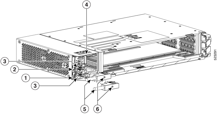
The NCS 2002 has redundant –48 VDC #12 single-hole lug power terminals. The terminals are labeled RET(A), RET(B), -48V(A), and -48V(B) on the power module.

To install redundant DC power feeds, use four power cables and one ground cable. For a single power feed, only two power cables (#12 AWG or larger, copper conductor, 194 degrees F [90 degrees C] minimum) and one ground cable (#6 AWG or larger) are required. Use a conductor with low impedance to ensure circuit overcurrent protection. However, the conductor must have the capability to safely conduct any faulty current that might be imposed. For a DC power supply, the fuse rating must not exceed 15A. The voltages –40.5 VDC and –57.6 VDC are, respectively, the minimum and maximum voltages required to power the chassis. The nominal steady state voltage is -48 VDC.


Note


Functionality is guaranteed at –40 VDC input voltage, as defined in Telcordia GR-1089-CORE, Issue 5.

We recommend the following wiring conventions, but customer conventions prevail:

  • Red wire for battery connections (–48 VDC).
  • Black wire for battery return connections (RET).
  • The battery return connection is treated as DC-I, as defined in Telcordia GR-1089-CORE, Issue 6.

The ground lug must be a dual-hole type, UL Listed, CSA certified and rated to accept the #6 AWG cable. Two ground posts with two M5 nuts are provided on the NCS 2002 to accommodate the dual-hole lug.

ETSI Power and Ground

For AC power feed, use the power cable shipped with the NCS 2002 and one ground cable. For an AC power supply, the fuse rating must not exceed 10A, 15A, or 20A. For low input voltage ranges, 100V to 127Vac, the branch circuit protection must not be rated more than 20A. The overcurrent/short circuit protection must be in accordance with local and national electrical codes. The voltage rating value for AC power ranges between 100 VAC to 240 VAC depending on the standards in various countries. This product is intended for use on the TN and TT power systems.

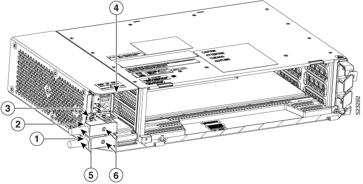
The NCS 2002 for ETSI has redundant –48 VDC power connectors (DSUB for DC power module) on the DC power module. To install redundant power feeds, use the two power cables shipped with the NCS 2002 shelf and one ground cable. For a DC power supply, the fuse rating must not exceed 15A. The voltages –40.5 VDC and –57.6 VDC are, respectively, the minimum and maximum voltages required to power the chassis. The nominal steady state voltage is -48 VDC.

The ground lug must be a dual-hole type, UL Listed, CSA certified and rated to accept the #6 AWG cable. Two ground posts with two M5 nuts are provided on the NCS 2002 to accommodate the dual-hole lug.


Caution


Only use the power cables shipped with the NCS 2002 shelf.


NTP-L35 Installing the Power and Ground to the NCS 2002 Shelf

Purpose

This procedure installs power feeds and grounds the NCS 2002 system.

Tools/Equipment

ANSI and ETSI:

  • #2 Phillips Dynamometric screwdriver
  • Medium slot-head screwdriver
  • Small slot-head screwdriver
  • Screws
  • Ground cable 13.3-mm² (#6 AWG) stranded
  • Listed pressure dual-holes lugs suitable for #6 AWG copper conductors
  • Wire cutters
  • Wire strippers
  • Crimp tool
  • Fuse panel

ANSI only:

  • Power cable (from fuse panel to assembly), #12 AWG, copper conductors, 194 degrees F [90 degrees C])
  • Wire wrapper
  • Two-hole grounding lug, shipped with the NCS 2002 ANSI

ETSI only:

  • Power cable (from fuse panel to power modules), shipped with the NCS 2002 ETSI
  • Two-hole grounding lug, shipped with the NCS 2002 ETSI

Prerequisite Procedures

Required/As Needed

Required

Onsite/Remote

Onsite

Security Level

None


Warning


To ensure safety of personnel and equipment, do not connect any power cables into the power module until the module is completely installed into the chassis. Statement 389


Warning


To reduce the risk of electric shock, switch on the power only after the power cord is completely installed into the power module. Statement 390


Warning


Blank faceplates (filler panels) serve three important functions: they prevent exposure to hazardous voltages and currents inside the chassis; they contain electromagnetic interference (EMI) that might disrupt other equipment; and they direct the flow of cooling air through the chassis. Do not operate the system unless all cards, power modules, and faceplates are in place. Statement 261


Warning


This equipment must be grounded. Never defeat the ground conductor or operate the equipment in the absence of a suitably installed ground conductor. Contact the appropriate electrical inspection authority or an electrician if you are uncertain that suitable grounding is available. Statement 1024


Warning


Never install an AC power module and a DC power module in the same chassis. Statement 1050


Warning


When stranded wiring is required, use approved wiring terminations, such as closed-loop or spade-type with upturned lugs. These terminations should be the appropriate size for the wires and should clamp both the insulation and conductor. Statement 1002


Warning


Before performing any of the following procedures, ensure that power is removed from the DC circuit. Statement 1003


Warning


Before working on a chassis or working near power supplies, unplug the power cord on AC units. Statement 246


Warning


This equipment is intended to be grounded. Ensure that the host is connected to earth ground during normal use. Statement 39


Warning


Use copper conductors only. Statement 1025


Warning


Connect the unit only to DC power source that complies with the safety extra-low voltage (SELV) requirements in IEC 60950-1 based safety standards. Statement 1033


Warning


This product requires short-circuit (overcurrent) protection, to be provided as part of the building installation. Install only in accordance with national and local wiring regulations. Statement 1045


Warning


This product relies on the building's installation for short-circuit (overcurrent) protection. Ensure that the protective device is rated not greater than: 10A-20A, 100-240 VAC~. Statement 1005


Warning


A readily accessible two-poled disconnect device must be incorporated in the fixed wiring. Statement 1022


Warning


This unit might have more than one power supply connection. All connections must be removed to de-energize the unit. Statement 1028


Caution


Always use the supplied ESD wristband when working with a powered NCS. For detailed instructions on how to wear the ESD wristband, refer to the Electrostatic Discharge and Grounding Guide for Cisco NCS 2000 Series .


Procedure


Step 1

Verify that the correct fuse panel is installed in the top mounting space:

  • For a DC power supply, the fuse rating must not exceed 15A.

  • For an AC power supply, the fuse rating must not exceed 10A, 15A, or 20A. For low input voltage ranges, 100V to 127Vac, the branch circuit protection must not be rated more than 20A. The overcurrent/short circuit protection must be in accordance with local and national electrical codes.

Step 2

Depending on the shelf and the power module installed, complete the necessary task:

Step 3

Connect the office ground to the NCS 2002 shelf. For detailed instructions on grounding, refer to the Electrostatic Discharge and Grounding Guide for Cisco NCS 2000 Series .

Step 4

Complete DLP-L53 Turning On and Verifying DC Office Power on the NCS2002Shelf.

Step 5

Continue with the NTP-L35 Installing the Fan-Tray Assembly in the NCS 2002 Shelf.

Stop. You have completed this procedure.


DLP-L49 Connecting Office Power (AC) to the NCS 2002 Shelf

Purpose

This task connects AC power to the NCS 2002 shelf.

Tools/Equipment

  • #2 Phillips Dynamometric screwdriver
  • Medium slot-head screwdriver
  • Small slot-head screwdriver
  • Wire wrapper
  • Wire cutters
  • Wire strippers
  • Crimp tool
  • Fuse panel
  • Ground cable 13.3-mm² (#6 AWG) stranded. The PIDs of the power cables are listed in the table below.

Prerequisite Procedures

Required/As Needed

Required

Onsite/Remote

Onsite

Security Level

None


Note


This product is intended for use on the TN and TT power systems.

Warning


When installing or replacing the unit, the ground connection must always be made first and disconnected last. Statement 1046


Warning


This equipment shall be connected to AC mains provided with a surge protective device (SPD) at the service equipment complying with NFPA 70, the National Electrical Code (NEC). Statement 7012


Caution


The NCS 2002 relies on the protective devices in the building installation to protect against short circuit, overcurrent and ground faults. Ensure that the protective devices are properly rated and comply with national and local codes.


Note


Not more than 7 feet (2 m) of the power supply cable should be exposed between the equipment and the fiber storage tray.

Caution


When terminating the frame ground, do not use soldering lug connectors, screwless (push-in) connectors, quick connect connectors, or other friction-fit connectors.


Note


If the system loses power or if both TNC, TNCE, TSC, or TSCE cards are reset, you must reset the NCS 2002 clock. After powering down, the date defaults to January 1, 1970, 00:04:15. To reset the clock, see NTP-G24 Set Up Name, Date, Time, and Contact Information .

Procedure


Step 1

Verify that the AC power module is installed in Slot A of the NCS 2002.

Step 2

Attach the AC power cable to the cable connector in the AC power module (see the figure below).

Figure 1. Connecting Office Power—AC Power Modules
Connecting Office Power—AC Power Modules

Step 3

Close the cable clip to secure the power cable (see the figure below).

Figure 2. Cable Clip to Secure the Power Cable
Cable Clip to Secure the Power Cable

Step 4

Connect the power cable to the fuse panel or power source.

Note

 
The voltage rating value for AC power ranges between 100 VAC to 240 VAC depending on the standards in various countries.

Note

 
Turn on the power after installing the power cables.

Step 5

Return to your originating procedure (NTP).

Table 1. PIDs for AC Power Cables

Cable

PID

AC power cable - Japan right exit

15454-M-CBL-R-JPN=

AC power cable - China right exit

15454-M-CBL-R-CHI=

AC power cable - India right exit

15454-M-CBL-R-IND=

AC power cable - EU right exit

15454-M-CBL-R-EU=

AC power cable - ARG right exit

15454-M-CBL-RARG=

AC power cable - AUS right exit

15454-M-CBL-RAUS=

AC power cable - UK right exit

15454-M-CBL-R-UK=

AC power cable - KOR right exit

15454-M-CBL-RKOR=

AC power cable ANSI 110VAC right exit

15454-M-ACCBL-R=

AC power cable ANSI 220VAC right exit

15454-M-ACCBL-R2=

AC power cable for data center right exit

15454-M-ACL6-R=


DLP-L50 Connecting Office Power (DC) to the NCS 2002 Shelf (ANSI Only)

Purpose

This task connects DC power to the NCS 2002 shelf (ANSI Only).

Tools/Equipment

  • #2 Phillips Dynamometric screwdriver

  • Medium slot-head screwdriver

  • Small slot-head screwdriver

  • Wire wrapper

  • Wire cutters

  • Wire strippers

  • Crimp tool

  • Open-end wrench or hex tube screw driver

  • Fuse panel

  • Power cable (from fuse panel to assembly), #12 AWG, copper conductors, 194 degrees F [90 degrees C])

  • Ground cable #6 AWG stranded

  • Listed pressure dual-holes lugs suitable for #6 AWG copper conductors

Prerequisite Procedures

Required/As Needed

Required

Onsite/Remote

Onsite

Security Level

None


Warning


When installing or replacing the unit, the ground connection must always be made first and disconnected last. Statement 1046


Warning


Hazardous voltage or energy may be present on DC power terminals. Always replace cover when terminals are not in service. Be sure uninsulated conductors are not accessible when cover is in place. Statement 1075


Caution


The NCS 2002 relies on the protective devices in the building installation to protect against short circuit, overcurrent, and ground faults. Ensure that the protective devices are properly rated and comply with national and local codes.


Note


The battery return connection is treated as DC-I, as defined in Telcordia GR-1089-CORE Issue 5.

Note


If the system loses power or both TNC, TNCE, TSC, or TSCE cards are reset and the system is not provisioned to get the time from a Network Time Protocol/Simple Network Time Protocol (NTP/SNTP) server, you must reset the NCS clock. After powering down, the date defaults to January 1, 1970, 00:04:15. To reset the clock, see the NTP-G24 Set Up Name, Date, Time, and Contact Information . If you are using the TNC, TNCE, TSC, or TSCE cards, the system clock runs for up to 3 hours. In this case, no action would be required.

Procedure


Step 1

Connect the return cables of the power supply to the Earth ground located at the power supply side.

Step 2

Connect the office power according to the fuse panel engineering specifications.

Step 3

Measure and cut the cables as needed to reach the NCS 2002 from the fuse panel.

Step 4

Dress the power according to local site practice.

Step 5

Strip 1/2 inch (12.7 mm) of insulation from all power cables that you use.

Step 6

Crimp the lugs onto the ends of all power leads.

Step 7

Verify that the DC power module is installed in Slot A.

Step 8

Remove the screws from the terminal block protective cover from the DC power module (see the figure below).

Figure 3. Connecting Office Power—DC Power Module (ANSI Only)

Step 9

Insert the lugs as shown in the figure below.

Figure 4. Connecting Office Power—DC Power Module (ANSI Only)
Figure 5. Connecting Office Power—Modular DC Power Module (ANSI Only)

1

PSU A

2

PSU B

3

Terminal block connectors

4

Slot A

5

Lugs

6

Screws

7

Terminal block cover

Note

 
There are two DC power terminals—A and B. Each power terminal is connected with two cables—One for RET and the other for -48V.

Step 10

Tighten the screws to a torque value of 7 in-lb (0.79 N-m) to lock the lugs.

Step 11

Tighten the screws to a torque value of 4 in-lb (0.45 N-m) of the terminal block protective cover on the DC power module (see the figure below).

Note

 
Use only pressure terminal connectors, such as ring and fork types, when terminating the battery, battery return, and frame ground conductors.
Figure 6. Connecting Office Power—DC Power Modules (ANSI Only)
Connecting Office Power—DC Power Modules (ANSI Only)

Caution


Before you make any crimp connections, coat all bare conductors (battery, battery return, and frame ground) with an appropriate antioxidant compound. Bring all unplated connectors, braided strap, and bus bars to a bright finish, then coat with an antioxidant before you connect them. You do not need to prepare tinned, solder-plated, or silver-plated connectors and other plated connection surfaces, but always keep them clean and free of contaminants.

Caution


When terminating power, return (RET), and frame ground, do not use soldering lug, screwless (push-in) connectors, quick-connect, or other friction-fit connectors.

Step 12

Return to your originating procedure (NTP).


DLP-L51 Connecting Office Power (DC) to the NCS 2002 Shelf (ETSI Only)

Purpose

This task connects power to the NCS 2002 shelf (ETSI Only).

Tools/Equipment

  • #2 Phillips Dynamometric screwdriver

  • Medium slot-head screwdriver

  • Small slot-head screwdriver

  • Wire wrapper

  • Wire cutters

  • Wire strippers

  • Crimp tool

  • Fuse panel

  • Ground cable #6 AWG stranded. The PID of the DC power cable for ETSI left exit is NCS2002-DCCBL-LE=.

Prerequisite Procedures

Required/As Needed

Required

Onsite/Remote

Onsite

Security Level

None


Warning


When installing or replacing the unit, the ground connection must always be made first and disconnected last. Statement 1046


Warning


Hazardous voltage or energy may be present on DC power terminals. Always replace cover when terminals are not in service. Be sure uninsulated conductors are not accessible when cover is in place. Statement 1075


Note


The battery return connection is treated as DC-I, as defined in Telcordia GR-1089-CORE Issue 5.

Caution


The NCS 2002 relies on the protective devices in the building installation to protect against short circuit, overcurrent, and ground faults. Ensure that the protective devices are properly rated and comply with national and local codes.


Note


If the system loses power or both TNC, TNCE, TSC, or TSCE cards are reset and the system is not provisioned to get the time from a Network Time Protocol/Simple Network Time Protocol (NTP/SNTP) server, you must reset the NCS clock. After powering down, the date defaults to January 1, 1970, 00:04:15. To reset the clock, see the NTP-G24 Set Up Name, Date, Time, and Contact Information . If you are using the TNC, TNCE, TSC, or TSCE cards, the system clock runs for up to 3 hours. In this case, no action would be required.

Procedure


Step 1

Connect the return cables of the power supply to the Earth ground located at the power supply side.

Step 2

Verify that the DC power module is installed in Slot A of the NCS 2002.

Figure 7. Connecting Office Power—DC Power Module (ETSI Only)
Connecting Office Power DC Power Module (ETSI Only)
Figure 8. Connecting Office Power—Modular DC Power Module (ETSI Only)
Connecting Office Power New DC Power Module (ETSI Only)

1

PSU A

2

PSU B

3

D-sub connectors

4

Slot A

5

DC power cables

6

Screws

Step 3

Attach the DC ETSI power cables to the D-SUB power connectors of the DC power module (see the figure below).

Step 4

Tighten the screws to a torque value of 4 in-lb (0.45 N-m) to secure the cable.

Figure 9. Connecting Office Power—DC Power Module (ETSI Only)
Connecting Office Power - DC Power Module (ETSI Only)
Figure 10. Connecting Office Power—Modular DC Power Module (ETSI Only)

1

PSU A

2

PSU B

3

D-sub connectors

4

Slot A

5

DC power cables

6

Screws

Note

 
Use only pressure terminal connectors, such as ring and fork types, when terminating the battery, battery return, and frame ground conductors.

Caution


Before you make any crimp connections, coat all bare conductors (battery, battery return, and frame ground) with an appropriate antioxidant compound. Bring all unplated connectors, braided strap, and bus bars to a bright finish, then coat with an antioxidant before you connect them. You do not need to prepare tinned, solder-plated, or silver-plated connectors and other plated connection surfaces, but always keep them clean and free of contaminants.

Caution


When terminating power, return, and frame ground, do not use soldering lug, screwless (push-in) connectors, quick-connect, or other friction-fit connectors.

Step 5

Return to your originating procedure (NTP).


DLP-L52 Turning On and Verifying AC Office Power on the NCS 2002 Shelf

Purpose

This task measures the power to verify correct power and returns for the NCS 2002 shelf.

Tools/Equipment

Voltmeter

Prerequisite Procedures

Required/As Needed

Required

Onsite/Remote

Onsite

Security Level

None


Caution


Do not apply power to the shelf until you complete all the installation steps.


Warning


To ensure safety of personnel and equipment, do not connect any power cables into the power module until the module is completely installed into the chassis. Statement 389


Warning


To reduce the risk of electric shock, switch on the power only after the power cord is completely installed into the power module. Statement 390


Procedure


Step 1

To power up the node, insert the fuse into the fuse position according to site practice. The fuse rating must not exceed 15A in case of AC power.

Step 2

If the NCS 2002 does not power up, check the voltage at the power source using a voltmeter. The voltage should be 100 to 240 VAC +/-10 percent.

Step 3

Return to your originating procedure (NTP).


DLP-L53 Turning On and Verifying DC Office Power on the NCS2002Shelf

Purpose

This task measures the power to verify correct power and returns for the NCS 2002 shelf.

Tools/Equipment

Voltmeter

Prerequisite Procedures

Required/As Needed

Required

Onsite/Remote

Onsite

Security Level

None


Caution


Do not apply power to the shelf until you complete all installation steps.


Warning


To ensure safety of personnel and equipment, do not connect any power cables into the power module until the module is completely installed into the chassis. Statement 389


Warning


To reduce the risk of electric shock, switch on the power only after the power cord is completely installed into the power module. Statement 390


Procedure


Step 1

Using a voltmeter, verify the office battery and ground at the following points on the fuse panel:

  1. To verify the power, place the black test lead of the voltmeter to the frame ground. Place the red test lead on the A-side connection and verify that it is between –40.5 VDC and –57.6 VDC. Place the red test lead on the B-side connection and verify that it is between –40.5 VDC and –57.6 VDC.

    Note

     
    The voltages –40.5 VDC and –57.6 VDC are, respectively, the minimum and maximum voltages required to power the chassis. The nominal steady state voltage is -48 VDC.
  2. To verify the ground, place the black test lead of the voltmeter to the frame ground. Place the red test lead on the A-side return ground and verify that no voltage is present. Place the red test lead on the B-side return ground and verify that no voltage is present.

Step 2

To power up the node, insert the fuse into the fuse position according to site practice. The fuse rating must not exceed 15A.

Step 3

Using a voltmeter, verify the NCS 2002 shelf for –48 VDC battery and ground:

  1. To verify the A-side of the shelf, place the black lead of the voltmeter to the frame ground. Place the red test lead to the -48V (A-side battery connection) red cable. Verify that it reads between –40.5 VDC and –57.6 VDC. Then place the red test lead of the voltmeter to the RET1 (A-side return ground) black cable and verify that no voltage is present.

    Note

     
    The voltages –40.5 VDC and –57.6 VDC are, respectively, the minimum and maximum voltages required to power the chassis.
  2. To verify the B-side of the shelf, place the black test lead of the voltmeter to the frame ground. Place the red test lead to the -48V (B-side battery connection) red cable. Verify that it reads between –40.5 VDC and –57.6 VDC. Then place the red test lead of the voltmeter to the RET2 (B-side return ground) black cable and verify that no voltage is present.

Step 4

Return to your originating procedure (NTP).