COE-PCE Initiated SR Policy with IGP Autoroute Announce

Table 1. Feature History

Feature Name

Release Information

Feature Description

PCE Initiated SR Policy with IGP Autoroute Announce

Cisco IOS XE Bengaluru 17.7.1a Cupertino

This feature enables a steering mechanism in which IGPs automatically use the policy for destination's downstream of the policy end point.

As part of a tactical TE solution, the Path Computation Element (PCE) can provision a Segment Routing Traffic Engineering (SR-TE) policy to mitigate link congestion.

Autoroute announcement is a steering mechanism in which IGPs automatically use the policy for destination's downstream of the policy end point. Autoroute announcement is performed using Cisco Crossworks Optimization Engine (COE). COE provides real-time network optimization allowing operators to maximize network utilization effectively and increase service velocity.

A PCE collects various pieces of network information to determine traffic flows causing link congestion. The PCE computes a suitable path to divert those flows and to alleviate the congestion. The PCE then deploys the SR-TE policy to divert the traffic leading to the congestion using the Stateful Path Computation Element Protocol (PCEP) to provision the policy. When the congestion is alleviated, the SR-TE policy is removed.

The PCEP message contains SID list to be deployed by the head-end. Path Computation Client (PCC) profiles allow activation of autoroute announce for the policy provisioned by PCEP, using the profile IDs. The profile ID on the PCE and PCC should match, otherwise the policy is not provisioned. For example, if the PCE provisions a policy with profile ID 1 and the head-end where the policy is being provisioned also has the PCC profile ID 1 configured with autoroute announce, COE-PCE initiated SR policy is activated for that policy.

COE-PCE Initiated SR Policy
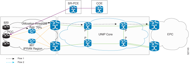
Figure 1. COE-PCE Initiated SR Policy

The preceding topology shows how an SR-PCE policy is initiated from COE:

  • SR policy is configured on the COE with profile ID.

  • COE pushes the SR policy to PCE and PCE forwards the SR policy to PCC.

  • Profile ID on PCC is matched with the profile ID on COE-PCE.

  • IGP autoroute announce is configured on the PCC.

  • The policy gets provisioned.

  • The data traffic now adheres to the SR policy that is pushed from the COE.

  • Complete SR Policy manipulation occurs only on COE.

Restrictions for PCE Initiated SR Policy

  • A maximum of 500 SR policies are supported.

  • Only native COE is supported.

  • Effective Cisco IOS XE Bengaluru 17.5.1, Bandwidth optimization based on SR tactical policy is supported on RSP3.

  • Bandwidth optimization by using COE is not supported.

  • PIC core is not supported over SR-TE tunnel.

  • PIC edge over SR-TE is not supported.

  • Effective Cisco IOS XE Bengaluru 17.5.1, ECMP over SR-TE is supported on RSP3.

  • 6PE and 6VPE are not supported with three and four transport labels.

  • IPv6 is not supported.

  • A maximum of 10,000 VPNv4 prefix limits are supported.

  • BGP LU (RFC 3107) is not supported for intra-AS and inter-AS.

ECMP Over SR-TE

Table 2. Feature History

Feature Name

Release Information

Feature Description

ECMP over SR-TE Policy

Cisco IOS XE Bengaluru 17.5.1

This feature allows you to configure ECMP over SR-TE policies. In case of multiple paths, this feature enables mitigation of local congestion through load balancing.

This feature is supported only on Cisco ASR 900 RSP3 module.

The following sections explain how local congestion can be mitigated and how ECMP can be deployed over SR-TE policies to attain load balancing.


Note


The traffic that is load balanced over multiple paths is HW-load balanced.


Restrictions for ECMP over SR-TE Policies

Cisco ASR 900 RSP3 module supports sr_5_label_push_enable and sr_pfp_enable templates. Following restrictions apply for different template combinations.

With sr_5_label_push_enable template:

  • Only one service label is supported with LB over SR-TE tunnels with three or four TE labels. This service label includes L3VPN, L2VPN, 6PE, 6VPE, and RFC 3107 BGP-LU label.

  • 6PE and 6VPE are not supported with three and four SR-TE tunnel labels.

  • Segment routing is not supported in enable_portchannel_qos_multiple_active template.

  • HW load balancing for L2VPN/EVPN services is not supported if the L2VPN/EVPN destination has a static route configured over SR-TE tunnel.

With sr_pfp_enable template:

  • SR PM HW time stamping is not supported.

  • VLAN COS marking is not supported.

  • HW load balancing is not supported.

  • Policer based hierarchical QOS on the ingress is not supported.

  • Short-Pipe tunneling mode is not supported.

Other Restrictions:

  • ECMP over SR-TE is not supported with COE.

  • PIC core over SR-TE tunnels are not supported.

  • PIC edge over SR TE tunnels are not supported.

  • PIC edge multipath over SR TE tunnels are not supported.

  • W-ECMP is not supported.

  • Next hop ECMP is not supported within an SR policy.

  • Local congestion mitigation (LCM) is applicable only for best effort traffic. All other delay sensitive traffic uses safe SIDs (Flex Algo 128). Delay sensitive traffic is not redirected using the LCM tunnels.

Local Congestion Mitigation

In today’s network deployments it is important for every router in the network to have the capability to provision the traffic in such a way that it avoids the congestion based on the amount of traffic ingressing and egressing out of it. In order to provision this congestion mitigation, it is essential for the routers to support Equal Cost Multi-Path (ECMP) load balancing, that is, distributing the traffic based on the number of paths available to reach the destination.

Congestion mitigation helps the routers to move certain traffic to a different path than the current path, using the tactical SR policies. When the link congestion threshold is crossed, the COE (Cisco Optimization Engine) that monitors the link congestion based on the interface counters, pushes these tactical policies using PCE. These PCE initiated tactical policies that are used for local congestion mitigation (LCM) are deployed when necessary and only best effort traffic is load balanced over these tactical SR-TE policies.

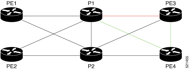
Figure 2. Illustration of Local Congestion Mitigation

In the above topology, let us assume that the best effort traffic is coming in to P1 from PE1 and PE2 for the destination PE3 and the link between P1 and PE3 is congested. To mitigate the congestion between P1 and PE3, ECMP paths from P1 and PE3 are required. With segment routing this is achieved by deploying multiple tactical SR policies from P1 to PE3, one through directly connected link P1-PE3 and the other through the path P1-PE4-PE3. These policies are called tactical policies and are used to avoid local congestion mitigation by load balancing the best effort traffic over these tactical policies. The LCM is applicable only for best effort traffic. All other delay sensitive traffic would use safe SIDs (Flex Algo 128). Delay sensitive traffic is not redirected using the LCM tunnels. Originating traffic is directed on non-LCM tunnels and transiting traffic with safe-SIDs is treated as normal label entry traffic and forwarded accordingly.

In the above topology, any node may deploy LCM tactical tunnels to mitigate congestion over a particular link. These nodes transit or sometimes originate the traffic to the LCM tunnel end points or even beyond the tunnel end points.

Let us assume that PE nodes originate the traffic and P nodes are transit node for the traffic originated somewhere else. Based on these combinations following are the different types of traffic that have to be considered:

As a PE Node,

  • L3VPN best effort traffic

  • L2VPN best effort traffic

  • Global traffic

As a P node,

  • Any traffic that comes in for a non-flexible algorithm 0 label is treated as an entry swap on the Label lookup.

  • Any traffic that comes in for flexible algorithm 0 label is treated as a swap case or it may be translated to pop and push stack of labels, if there is an LCM created for that outgoing link based on congestion.

Based on the number of TE labels that the LCM tunnels have to push, the number of labels outside of TE labels can be either one or two (service labels).

Load Balancing

At the head end, following are the different types of traffic that is subjected to load balancing. The traffic type here includes both best effort and delay sensitive.

As a PE Node,

  • L3VPN traffic

  • L2VPN traffic

  • Global traffic

As a P node,

  • Any traffic that comes in is treated based on the Label lookup.

Autoroute Announcement

Autoroute announcement or bandwidth optimization is used to steer traffic away from congested links and better utilize the network.

The PCEP message contains SID list to be deployed by the head-end. Path Computation Client (PCC) profiles allow autoroute announce to be activated for the policy instantiated by PCEP, using the profile IDs. For example, if the PCE instantiates a policy with profile ID 1 and the head-end where the policy is being instantiated has the PCC profile ID 1 configured with autoroute announce, PCE initiated SR policy is activated for that policy.

Autoroute announce can be configured under both policies created with strict SID and policies created with non-strict SID. The main difference between configuring autoroute under policies created with strict SID (assume A) and non-strict SID (assume B) is that with A, the lookup entry will be programmed only in RIB whereas with B, the lookup entry will be programmed in RIB and LFIB for flexible algorithm label 0.

Static Route Configuration

By adding a static route to the same destination but with different tunnels having the same endpoint, a load balancing is formed for the route over the tunnels configured. This is applicable for all types of traffic.

Next Hop ECMP within a SR Policy

If there is a SR policy created to a destination with a set of SIDs and the SR policy headend have multiple equal paths to reach the next hop, no ECMP is formed to reach the next hop within the SR policy.

Configuring with IGP Autoroute Announce

pce
    address ipv4 10.13.13.13
segment-routing traffic-eng
   peer ipv4 10.1.1.1  
    segment-list name ss1
    
    policy 100
     binding-sid mpls 15999
     color 100 end-point ipv4 10.12.12.12
     candidate-paths
      preference 10
       dataplane mpls
 profile-id 100

Now, to push the PCE initiated OSPF autoroute announce from PCE to PCC, the profile IDs on PCE and PCC must match. The below configuration shows the PCC configuration and that the profile ID is matching with PCE and thus the autoroute announce is enabled.

segment-routing traffic-eng                                                             
  pcc
  pce address 10.13.13.13 source-address 10.1.1.1
  profile 100
   autoroute
    include all

Verifying SR Policy with Autoroute Announce

ASR903-R1#show segment-routing traffic-eng policy all

Name: *10.12.12.12|100 (Color: 100 End-point: 10.12.12.12)
Owners : PCEP
Status:
Admin: up, Operational: up for 66:41:16 (since 09-18 16:56:50.444)
Candidate-paths:
Preference 10 (PCEP):
PCC profile: 100
Dynamic (pce 10.13.13.13) (active)
Metric Type: TE, Path Accumulated Metric: 5
16003 [Prefix-SID, 10.3.3.3]
16012 [Prefix-SID, 10.12.12.12]
Attributes:
Binding SID: 15999
Allocation mode: explicit
State: Programmed
Autoroute:
Include all

Verifying ISIS Autoroute for IGP

Use the following two commands to verify the ISIS Autoroute for IGP:

ASR903-R1#show ip cef 10.12.12.12 -------------IGP ROUTE
10.12.12.12/32
nexthop 10.12.12.12 Tunnel65536 ------------Tunnel pushed for IGP ROUTE
ASR903-R1# show ip cef 10.12.12.12 internal
10.12.12.12/32, epoch 3, RIB[I], refcnt 6, per-destination sharing
  sources: RIB 
  feature space:
    IPRM: 0x00028000
    Broker: linked, distributed at 1st priority
    LFD: 10.12.12.12/32 0 local labels
        contains path extension list
  ifnums:
    Tunnel65536(64)
  path list 3C97B678, 3 locks, per-destination, flags 0x49 [shble, rif, hwcn]
    path 3E393010, share 1/1, type attached nexthop, for IPv4
      MPLS short path extensions: [rib | lblmrg | srlbl] MOI flags = 0x1 label implicit-null
      nexthop 10.12.12.12 Tunnel65536, IP midchain out of Tunnel65536 2FFE3D00
  output chain:
    IP midchain out of Tunnel65536 2FFE3D00
    label [16012|16012]
    FRR Primary (0x3D9D4CE0)
      <primary: TAG adj out of Port-channel1, addr 10.100.0.2 3C9559C0>
      <repair:  TAG adj out of BDI1110, addr 10.111.0.2 3C954FC0>

Verify the Tunnel ID on the SR Policy

ASR903-R1# show segment-routing traffic-eng policy name margin detail
Name: Margin (Color: 1000 End-point: 10.12.12.12)
  Owners : CLI
  Status:
    Admin: up, Operational: up for 00:50:52 (since 09-16 11:00:06.697)
  Candidate-paths:
    Preference 10 (CLI):
      Dynamic (pce 10.13.13.13) (active)
        Metric Type: TE, Path Accumulated Metric: 5
          16012 [Prefix-SID, 10.12.12.12]
  Attributes:
    Binding SID: 15900
      Allocation mode: explicit
      State: Programmed
  IPv6 caps enabled
  Tunnel ID: 65536 (Interface Handle: 0x15B)
  Per owner configs:
    CLI
      Binding SID: 15900
  Stats:
    Packets: 535473 	Bytes: 805338440
Event history:
    Timestamp           	Client          	Event type          	Context: Value
    ---------           	------          	----------          	-------: -----
    09-16 11:00:06.377  	CLI             	Policy created      	Name: CLI
    09-16 11:00:06.418  	CLI             	Set colour          	Colour: 1000
    09-16 11:00:06.418  	CLI             	Set end point       	End-point: 10.12.12.12
    09-16 11:00:06.446  	CLI             	Set binding SID     	BSID: Binding SID set
    09-16 11:00:06.577  	CLI             	Set dynamic         	Path option: dynamic
    09-16 11:00:06.620  	CLI             	BSID allocated      	FWD: label 15900
    09-16 11:00:06.637  	FH Resolution   	Policy state UP     	Status: PATH RESOLVED
    09-16 11:00:06.697  	FH Resolution   	Policy state DOWN   	Status: PATH NOT RESOLVED
    09-16 11:00:06.706  	CLI             	Set dynamic pce     	Path option: dynamic pce
    09-16 11:00:07.240  	FH Resolution   	Policy state UP     	Status: PATH RESOLVED
    09-16 11:00:09.520  	FH Resolution   	REOPT triggered     	Status: REOPTIMIZED