The documentation set for this product strives to use bias-free language. For the purposes of this documentation set, bias-free is defined as language that does not imply discrimination based on age, disability, gender, racial identity, ethnic identity, sexual orientation, socioeconomic status, and intersectionality. Exceptions may be present in the documentation due to language that is hardcoded in the user interfaces of the product software, language used based on RFP documentation, or language that is used by a referenced third-party product. Learn more about how Cisco is using Inclusive Language.
In order to support
segment routing, BGP requires the ability to advertise a segment identifier
(SID) for a BGP prefix. A BGP prefix SID is always global within the segment
routing BGP domain and identifies an instruction to forward the packet over the
ECMP-aware best path computed by BGP to the related prefix. The BGP prefix SID
identifies the BGP prefix segment.
Adjacency
SID
The adjacency segment
Identifier (SID) is a local label that points to a specific interface and a
next hop out of that interface. No specific configuration is required to enable
adjacency SIDs. Once segment routing is enabled over BGP for an address family,
for any interface that BGP runs over, the address family automatically
allocates an adjacency SID toward every neighbor out of that interface.
High Availability
for Segment Routing
In-service software
upgrades (ISSUs) are minimally supported with BGP graceful restart. All states
(including the segment routing state) must be relearned from the BGP router's
peers. During the graceful restart period, the previously learned route and
label state are retained.
Overview of BGP Egress Peer Engineering With Segment Routing
Cisco Nexus 9000 Series switches are often deployed in massive scale data centers (MSDCs). In such environments, there is
a requirement to support BGP Egress Peer Engineering (EPE) with Segment Routing (SR).
Segment Routing (SR) leverages source routing. A node steers a packet through a controlled set of instructions, known as segments,
by prepending the packet with an SR header. A segment can represent any topological or service-based instruction. SR allows
steering a flow through any topological path or any service chain while maintaining per-flow state only at the ingress node
of the SR domain. For this feature, the Segment Routing architecture is applied directly to the MPLS data plane.
In order to support Segment Routing, BGP requires the ability to advertise a Segment Identifier (SID) for a BGP prefix. A
BGP prefix is always global within the SR or BGP domain and it identifies an instruction to forward the packet over the ECMP-aware
best-path that is computed by BGP to the related prefix. The BGP prefix is the identifier of the BGP prefix segment.
The SR-based Egress Peer Engineering (EPE) solution allows a centralized (SDN) controller to program any egress peer policy
at ingress border routers or at hosts within the domain.
In the following example, all three routers run iBGP and they advertise NRLI to one another. The routers also advertise their
loopback as the next-hop and it is recursively resolved. This provides an ECMP between the routers as displayed in the illustration.
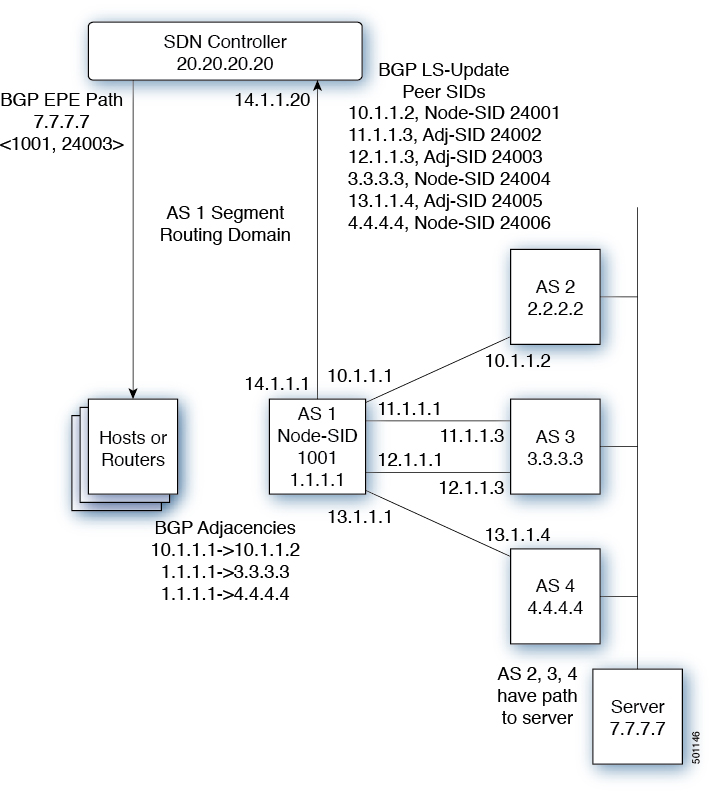
Figure 1. Example of Egress Peer Engineering
The SDN controller receives the Segment IDs from the egress router 1.1.1.1 for each of its peers and adjacencies. It can then
intelligently advertise the exit points to the other routers and the hosts within the controller’s routing domain. As displayed
in the illustration, the BGP Network Layer Reachability Information (NLRI) contains both the Node-SID to Router 1.1.1.1 and
the Peer-Adjacency-SID 24003 indicating that the traffic to 7.7.7.7 should egress over the link 12.1.1.1->12.1.1.3.
Guidelines and Limitations for BGP Egress Peer Engineering
BGP Egress Peer Engineering has the following guidelines and limitations:
BGP Egress Peer Engineering is only supported for IPv4 BGP peers. IPv6 BGP peers are not supported.
BGP Egress Peer Engineering is only supported in the default VPN Routing and Forwarding (VRF) instance.
Any number of Egress Peer Engineering (EPE) peers may be added to an EPE peer set. However, the installed resilient per-CE
FEC is limited to 32 peers.
A given BGP neighbor can only be a member of a single peer-set. Peer-sets are configured. Multiple peer-sets are not supported.
An optional peer-set name may be specified to add neighbor to a peer-set. The corresponding RPC FEC load-balances the traffic across all the peers
in the peer-set. The peer-set name is a string that is a maximum length of 63 characters (64 NULL terminated). This length
is consistent with the NX-OS policy name lengths. A peer can only be a member of a single peer-set.
Adjacencies for a given peer are not separately assignable to different peer-sets.
Beginning with Cisco NX-OS Release 9.3(3), BGP Egress Peer Engineering is supported on Cisco Nexus 9300-GX platform switches.
Configuring Neighbor Egress Peer Engineering Using BGP
With the introduction of RFC 7752 and draft-ietf-idr-bgpls-segment-routing-epe, you can configure Egress Engineering. The feature is valid only for external BGP neighbors and it is not configured by default.
Egress Engineering uses RFC 7752 encoding.
Before you begin
You must enable BGP.
After an upgrade from Release 7.0(3)I3(1) or Release 7.0(3)I4(1), configure the TCAM region before configuring Egress Peer
Engineering (EPE) on Cisco Nexus 9000 Series switches using the following commands:
switch# hardware access-list tcam region vpc-convergence 0
switch# hardware access-list tcam region racl 0
switch# hardware access-list tcam region mpls 256 double-wide
Save the configuration and reload the switch.
For more information, see the Using Templates to Configure ACL TCAM Region Sizes and Configuring ACL TCAM Region Sizes sections
in the Cisco Nexus 9000 Series NX-OS Security Configuration Guide.
Specifies whether a Peer-Node-SID is allocated for the neighbor and it is advertised in an instance of a BGP Link-State (BGP-LS)
address family Link NLRI. If the neighbor is a multi-hop neighbor, a BGP-LS Link NLRI instance is also advertised for each
Equal-Cost-MultiPath (ECMP) path to the neighbor and it includes a unique Peer-Adj-SID.
Optionally, you can add the neighbor to a peer-set. The Peer-Set-SID is also advertised in the BGP-LS Link NLRI in the same
instance as the Peer-Node-SID. BGP Link-State NLRI is advertised to all neighbors with the link-state address family configured.
See RFC 7752 and draft-ietf-idr-bgpls-segment-routing-epe-05 for more information on EPE.
Configuration Example for Egress Peer Engineering
See the Egress Peer Engineering sample configuration for the BGP speaker 1.1.1.1. Note that the neighbor 20.20.20.20 is the
SDN controller.
 hostname epe-as-1
install feature-set mpls
feature-set mpls

feature telnet
feature bash-shell
feature scp-server
feature bgp
feature mpls segment-routing

segment-routing mpls
vlan 1

vrf context management
  ip route 0.0.0.0/0 10.30.97.1
  ip route 0.0.0.0/0 10.30.108.1

interface Ethernet1/1
  no switchport
  ip address 10.1.1.1/24
  no shutdown

interface Ethernet1/2
  no switchport
  ip address 11.1.1.1/24
  no shutdown

interface Ethernet1/3
  no switchport
  ip address 12.1.1.1/24
  no shutdown

interface Ethernet1/4
  no switchport
  ip address 13.1.1.1/24
  no shutdown

interface Ethernet1/5
  no switchport
  ip address 14.1.1.1/24
  no shutdown

interface mgmt0
  ip address dhcp
  vrf member management


interface loopback1
  ip address 1.1.1.1/32
line console

line vty
ip route 2.2.2.2/32 10.1.1.2
ip route 3.3.3.3/32 11.1.1.3
ip route 3.3.3.3/32  12.1.1.3
ip route 4.4.4.4/32  13.1.1.4
ip route 20.20.20.20/32 14.1.1.20

router bgp 1
  address-family ipv4 unicast
  address-family link-state
 neighbor 10.1.1.2
    remote-as 2
    address-family ipv4
    egress-engineering
 neighbor 3.3.3.3
   remote-as 3
   address-family ipv4
   update-source loopback1
   ebgp-multihop 2
   egress-engineering
 neighbor 4.4.4.4
   remote-as 4
   address-family ipv4
   update-source loopback1
   ebgp-multihop 2
   egress-engineering
neighbor 20.20.20.20
   remote-as 1
   address-family link-state
   update-source loopback1
   ebgp-multihop 2
neighbor 124.11.50.5
    bfs
    remote-as 6
    update-source port-channel50.11
    egress-engineering peer-set pset2 <<<<<<<
    address-family ipv4 unicast
neighbor 124.11.101.2
    bfd
    remote-as 6
    update-source Vlan2401
    egress-engineering
    address-family ipv4 unicast
This example shows sample output for the show bgp internal epe command.
You can configure the BGP link state address family for a neighbor session with a controller to advertise the corresponding
SIDs. You can configure this feature in global configuration mode and neighbor address family configuration mode.
This command can also be configured in neighbor address-family configuration mode.
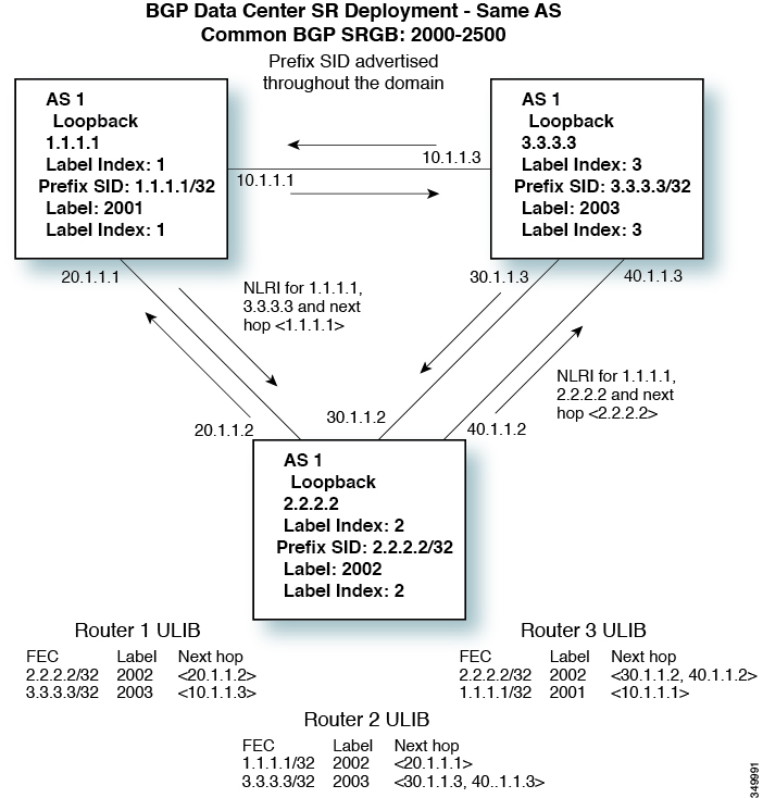
BGP Prefix SID
Deployment Example
In the simple example
below, all three routers are running iBGP and advertising Network Layer
Reachability Information (NRLI) to one another. The routers are also
advertising their loopback interface as the next hop, which provides the ECMP
between routers 2.2.2.2 and 3.3.3.3.
 Feedback