About Cisco Catalyst IW9167I Heavy Duty Access Point

Introduction to Cisco Catalyst IW9167I Heavy Duty Access Point

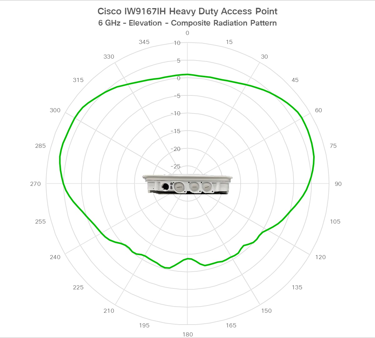
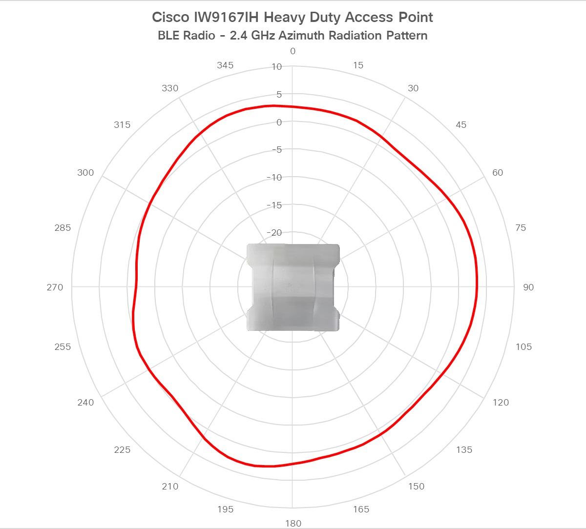
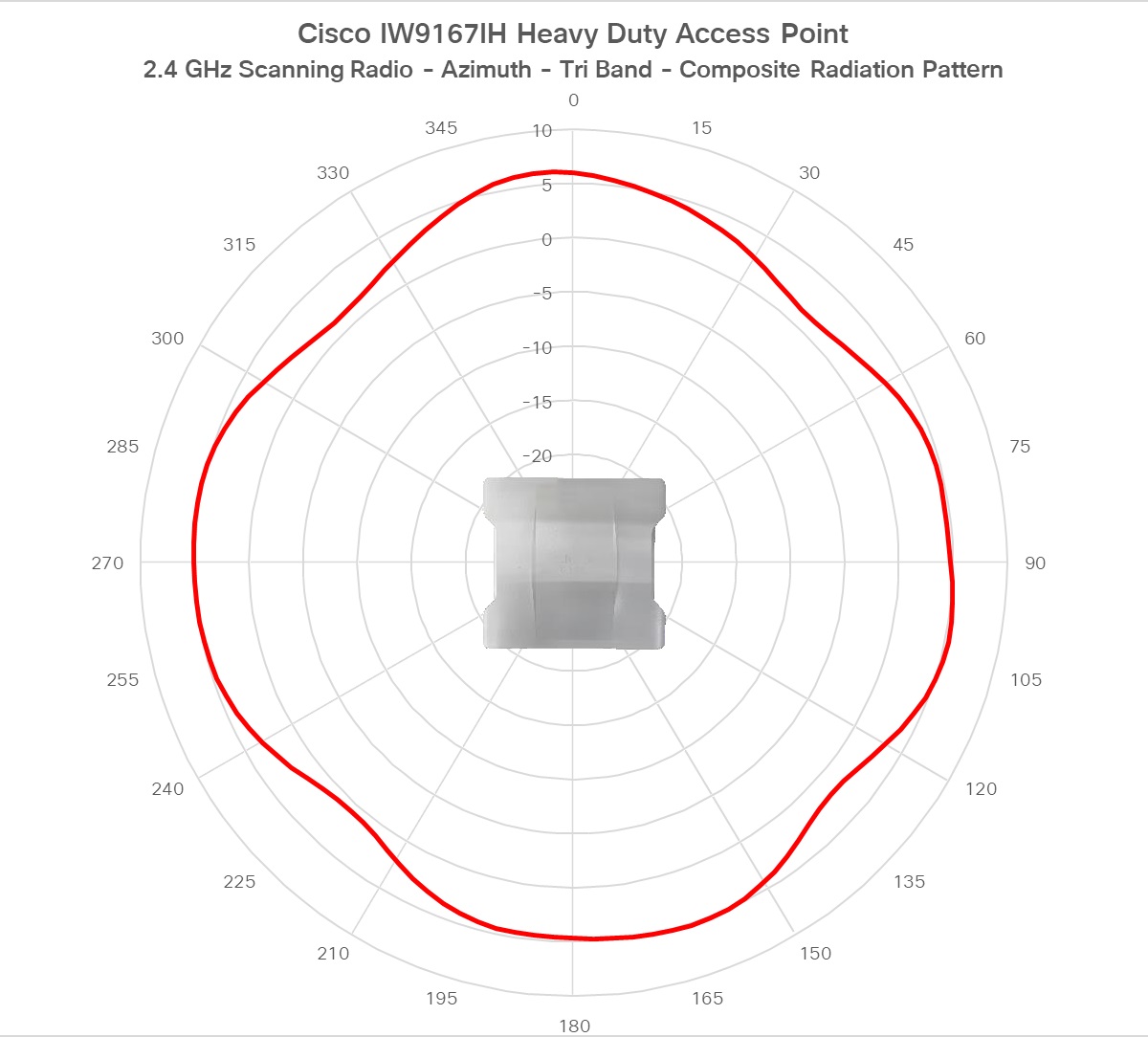
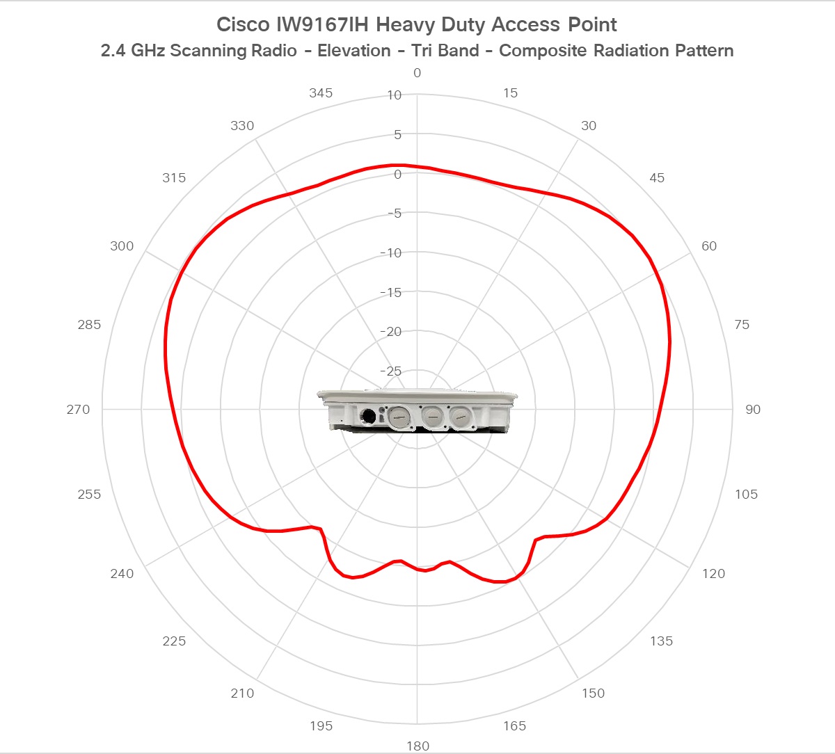
The Cisco Catalyst IW9167I Heavy Duty Access Point (hereafter referred to as IW9167I) is designed to make wireless deployments simple in outdoor and industrial environments. It is built with a cast-aluminum case that can handle water, dust, and extreme temperatures. It includes built-in antennas and supports Wi-Fi 6E to enable higher density, higher throughput, more channels, power efficiency, and improved security.

IW9167I includes 6 GHz hardware support.

The AP hardware is supported on the following platforms:

  • Cisco DNA Center on-premises

  • Cisco Catalyst stack

A full listing of the AP's features and specifications is provided in the Cisco Catalyst IW9167 Heavy Duty Access Point Data Sheet.

Cisco Catalyst IW9167I Heavy Duty Access Point Features

The Cisco Catalyst IW9167I Heavy Duty Access Point has the following features:

  • 2 GB DDR4 memory, 1 GB NAND Flash

  • Tri radios—2.4 GHz, 5 GHz, 6 GHz

  • Integrated antenna—2.4 GHz 4x4:4SS, 5 GHz 4x4:4SS, 6 GHz 4x4:4SS,

  • 2.4 GHz IoT Bluetooth Low Energy (BLE) radio

  • Integrated GNSS

  • 1 x multi-Gigabit (mGig) copper Ethernet port (supporting PoE, including IEEE 802.3at/bt, Cisco UPoE, 100 Mbps/1 Gbps/2.5 Gbps/5 Gbps)

  • 1 x SFP interface—Supports up to 10 Gbps

  • Optional M12 adapter for network and power interfaces

  • Dual power input options—PoE-in and 24 - 48VDC

  • Dual mounting options—Pole or wall mount

  • IP67 rating

  • Indoor and outdoor mode operation supported in different countries as shown in the following table:

    FCC

    Indoor and outdoor

    IC

    Outdoor

    CE

    Indoor and outdoor

    C-tick

    Outdoor

    Telec

    Outdoor

Connectors and Ports

The following figure shows the available ports on the AP front panel.

Figure 1. IW9167I Front Panel Connectors and Ports

1

Console port (RJ-45) and reset button

For information on how to use the Reset button, see Using the Reset Button.

2

Status LED

3

SFP (copper) 100M/1000M/10G Multigigabit Ethernet /M12 X-code or SFP (fiber) 1G/10G

Note


M12 X-code port by using M12-RJ45 adapter can support up to 2.5G rate.

4

100M/1000M/2.5G/5G Multigigabit Ethernet (RJ-45) / M12 X-code auto-sensing PoE+ in (802.3at/bt), UPOE-in

Note


M12 X-code port by using M12-RJ45 adapter can support up to 2.5G rate.

5

DC power input (micro-fit, or M12 4-pin A-code by using M12 adapter)

4-Pin Micro-Fit Connector for DC Power

The following figures show the 4-pin Micro-Fit connector for DC power.

Figure 2. Mating Connector Front View

Molex Micro-Fit Pin

Assignment

Pin 1

DC- (Negative Terminal)

Pin 2

Not assigned

Pin 3

DC+ (Positive Terminal)

Pin 4

Not assigned

M12-RJ45 Adapter

M12-RJ45 adapter (Cisco PID: IW-ACC-M12ETH=) can be used to support M12 X-coded connector.


Note


M12 X-code port by using M12-RJ45 adapter can support up to 2.5G rate.


Figure 3. M12-RJ45 Adapter (Cisco PID: IW-ACC-M12ETH=)

The following table shows the M12-RJ45 adapter pinouts.

Table 1. M12-RJ45 Pinouts

RJ45

Signal

M12 X-Code

1

B1_DA+

1

2

B1_DA-

2

3

B1_DB+

3

6

B1_DB-

4

7

B1_DD+

5

8

B1_DD-

6

5

B1_DC-

7

4

B1_DC+

8

M12-PWR Adapter

M12-PWR adapter (Cisco PID: IW-ACC-M12PWR=) can be used to support M12 A-coded DC power connector.

Figure 4. M12-PWR Adapter (Cisco PID: IW-ACC-M12PWR=)

The following table shows the M12-PWR adapter pinouts.

Table 2. M12-PWR Pinouts

Micro-FIT 4P

Wire

M12 A-Code

3

RED (22 AWG)

1

2

N/C

2

1

BLACK (22 AWG)

3

4

N/C

4

Power Sources

The IW9167I Access Point is supported on these power sources:

  • DC power: 24 to 48 VDC

  • Power over Ethernet (PoE): 802.3at (PoE+), 802.3bt (PoE++), Cisco Universal PoE (Cisco UPOE). For more information, see Powering the Access Point.


Warning


Connect the unit only to DC power source that complies with the safety extra-low voltage (SELV) requirements in IEC 60950 based safety standards. Statement 1033


Power Adapters

The IW9167I Access Point supports the following DC power adapters::

  • PID: IW-PWRADPT-MFIT4P=: Operating: -40°C to +65°C, 60W.

Power Injectors

The IW9167I Access Point supports the following power injectors:

  • IW-PWRINJ-60RGDMG=: Operating: -40°C to +70°C. Power derating of 60W at 70°C, and 65W at 65°C. Supports 100M/1G/2.5G/5G/10G rates.

  • AIR-PWRINJ-60RGD1=: Operation: -40°C to +50°C, 60W. Supports 10M/100M/1G rates.

  • AIR-PWRINJ-60RGD2=: Operation: -40°C to +50°C, 60W. Supports 10M/100M/1G rates.


Caution


When the AP is installed outdoors or in a wet or damp location, the AC branch circuit powering the AP should be provided with ground fault protection (GFCI), as required by Article 210 of the National Electrical Code (NEC).

Ethernet (PoE) Ports

The AP supports an Ethernet uplink port (also for PoE-IN). The Ethernet uplink port on the AP uses an RJ-45 connector (with weatherproofing) to link the AP to the 100BASE-T, 1000BASE-T, 2.5G BASE-T, or 5G BASE-T network. The Ethernet cable is used to send and receive Ethernet data and optionally supply inline power from the power injector or a suitably powered switch port.


Tip


The AP senses the Ethernet and power signals, and automatically switch internal circuitry to match the cable connections.

The Ethernet cable must be a shielded, outdoor rated, Category 5e (CAT 5e) or better cable. Category 6A (CAT 6A) cable is needed for 5G rate. The AP senses the Ethernet and power signals and automatically switches internal circuitry to match the cable connections.

SFP Option


Warning


Class 1 laser product. Statement 1008


The factory-orderable fiber option provides a fiber input and output capability. Fiber data is transmitted and received over a single or dual-strand fiber cable, depending on the SFP, which is connected to the access point using these SFP modules:

Table 3. Supported SFP Modules

PID

Distance

Fiber/Cable

Operating Temperature Range

GLC-SX-MM-RGD=

220-550m

MMF

IND

GLC-LX-SM-RGD=

550m/10km

MMF/SMF

IND

GLC-T-RGD=

100m

CAT 5e

IND

SFP-10G-LR10-I

10km

SMF

IND

SFP-10G-T-X

30m@10Gbps

CAT 6A/CAT 7

EXT


Note


SFP modules are not hot-swappable. When you plug and unplug the SFP module, a manual reload of the AP is required.


Client data is passed to the network controller through the fiber connection via a fiber-capable switch or controller. Configuration information can be found in the controller configuration guide of the switch or controller you are using.

Antennas and Radios

The following sections provide detailed information about the AP's antennas and radios.

Internal Antennas and GNSS Receiver

The IW9167I access point has the following internal antennas:

  • Four internal dual-band antennas with a dedicated 2.4 GHz radio and a 5 GHz radio

  • Four internal antennas with a dedicated 6 GHz radio

  • One internal single-band antenna with a dedicated 2.4 GHz IoT radio

  • Two tri-band antennas with a dedicated 2.4 GHz, 5 GHz, and 6 GHz Aux radio

The IW9167I is equipped with a standard-precision GNSS receiver for geolocation, with L1/G1/E1/B1 frequencies supported: 1.559 – 1.610 GHz. For best GNSS performance, the AP should be mounted outdoors with a clear view of the sky. Location accuracy may be affected if the antenna’s view is obstructed. The following figure shows the GNSS windows on the bottom of the access point.

Figure 5. GNSS Windows

1

GNSS windows

IW9167I (Internal Antenna) Radiation Patterns

The following illustrations show the IW9167I model with internal antenna radiation patterns:

Table 4. Cisco Catalyst IW9167I Radiation Patterns
Figure 6. IW9167I - Dual Band Composite Radiation Pattern (2.4-GHz Azimuth)
Figure 7. IW9167I - Dual Band Composite Radiation Pattern (2.4-GHz Elevation)
Figure 8. IW9167I - Dual Band Composite Radiation Pattern (5-GHz Azimuth)
Figure 9. IW9167I - Dual Band Composite Radiation Pattern (5-GHz Elevation)
Figure 10. IW9167I - Composite Radiation Pattern (6-GHz Azimuth)
Figure 11. IW9167I - Composite Radiation Pattern (6-GHz Elevation)
Figure 12. IW9167I - IoT (BLE) Antenna - Radiation Pattern (2.4-GHz Azimuth)
Figure 13. IW9167I - IoT (BLE) Antenna - Radiation Pattern (2.4-GHz Elevation)
Figure 14. IW9167I - Scanning Radio-Tri Band Composite Radiation Pattern (2.4-GHz Azimuth)
Figure 15. IW9167I - Scanning Radio-Tri Band Composite Radiation Pattern (2.4-GHz Elevation)
Figure 16. IW9167I - Scanning Radio-Tri Band Composite Radiation Pattern (5-GHz Azimuth)
Figure 17. IW9167I - Scanning Radio-Tri Band Composite Radiation Pattern (5-GHz Elevation)
Figure 18. IW9167I - Scanning Radio - Tri Band Composite Radiation Pattern (6-GHz Azimuth)
Figure 19. IW9167I - Scanning Radio - Tri Band Composite Radiation Pattern (6-GHz Elevation)