Overview of Cisco Catalyst 9800-L Wireless Controller

Cisco Catalyst 9800-L Wireless Controller is the first low-end controller that provides a significant boost in performance and features from Cisco 3504 Wireless Controller.

The following are the two variations of the controller:

  • Cisco Catalyst 9800-L Copper Series Wireless Controller (9800-L-C RJ45).

  • Cisco Catalyst 9800-L Fiber Series Wireless Controller (9800-L-F SFP).

For more information about features and benefits, see the Cisco Catalyst 9800-L Wireless Controller datasheet.

Figure 1. Cisco Catalyst 9800-L Copper Series Wireless Controller (9800-L-C RJ45)
Figure 2. Cisco Catalyst 9800-L Fiber Series Wireless Controller (9800-L-F SFP)

Summary of Cisco Catalyst 9800-L Wireless Controller Features

Table 1. Cisco Catalyst 9800-L Wireless Controller Features

Feature

Description

Chassis Height

One rack-unit (1RU)

Throughput

5 Gbps

Number of APs supported

250

Number of clients supported

5000

Processor

Intel Broadwell-NE DE—8-core, 2 GHz

Memory Options

  • Control/Data Plane Memory—16GB DDR4

  • Boot Flash—8MB

  • Bulk Flash—32GB eMMC

Redundancy, Service Ports

2x 1GE Cu

Data Ports

2x 1G/2.5G/5G/10G Cu (or) 2x 1G/10G Fiber, 4x 1G/2.5G Cu

Storage Temperature

–13° F to 158° F (–25° C to 70° C)

Operating Temperature

32° F to 104° F (0° C to 40° C)

Note


The maximum temperature is derated by 1.0° C for every 1000 ft (305 m) of altitude above sea level.

Storage Humidity

0% to 95% RH non-condensing

Operating Humidity

10% to 95% RH non-condensing

Operational Altitude

0 to 10,000 ft (3048m)

Power Adapter

110W single 12V output adapter (C9800-AC-110W)

Platform Components

Cisco Catalyst 9800-L Wireless Controller Front Panel

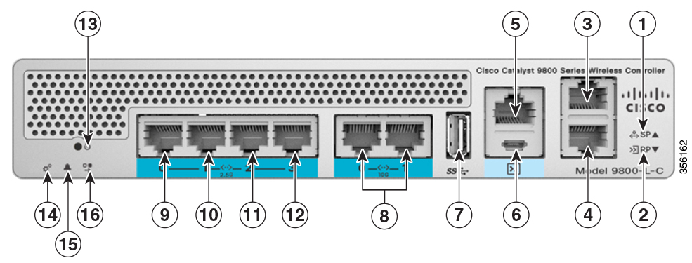
Figure 3. Cisco Catalyst 9800-L Wireless Controller Front Panel View
Table 2. Cisco Catalyst 9800-L Wireless Controller Front Panel Components

1

Service Port LED

2

Redundancy Port LED

3

Service Port (SP) (RJ-45) for out-of-band management

4

Redundancy Port (RP) (RJ-45).

Note


The redundancy ports can be connected back to back or via an L2 switch.

5

CPU console port, which is an RJ-45 RS-232 and micro-B USB serial console port. The default RJ-45 serial port settings are 9600, N, 8, 1. The boot-loader supports baud rates of 1200, 2400, 4800, 9600, 19200, 38400, 57600, and 115200. A default baud-rate recovery mechanism is not available; however, the bootloader ensures that the stored baud rate setting matches one of the allowed values before setting the baud rate. If a nonstandard value is detected, the baud rate will default to 9600.

Micro-B USB serial connection takes precedence over RJ-45 when both connections are made.

Note


If the Micro-B USB console port is used, the CPU console port that supports RJ-45 connector is ignored. That is, only one of the two ports are ever active.

6

Micro USB Type-B console port that can be used to perform software updates in addition to the already available transfer modes, namely HTTP, TFTP, FTP, and SFTP.

Note


If you connect both the Micro USB Type-B console port and the CPU console port, then USB port takes precedence and the CPU console port is ignored as only one of the two ports are ever active.

7

Type A 3.0 USB port used to perform software updates in addition to already available transfer mode, namely HTTP, TFTP, FTP, and SFTP.

8

2x 10 G/mGig ports. This mGig port supports speeds of 10G, 5G, 2.5G, and 1G.

Note


In a High Availability environment, it is not possible to change the configured port speed.

9, 10, 11, and 12

mGig ports. These mGig ports support only 2.5G and 1G speeds.

Gigabit Ethernet ports 1,2, 3, and 4 are RJ-45 connector form-factors. These ports are designed so that 1500 VAC rms isolation (per the 802.3 specification) is met between chassis ground and any Ethernet signal.

Note


The ports can be used for infra-switch connection using multiple an AP-Manager or data interface.

13

Reset button

  • Pushing the Reset button for less than 10 seconds will reload the controller.

  • Pushing the Reset button for more than 10 seconds will erase the startup configuration in NVRAM of the controller.

14

System LED that determines if the system is powered up and booted.

15

Alarm LED that determines a status or error occurred. The status or error is posted on the console screen.

16

High Availability LED

Front Panel LEDs: Definitions of States

Table 3. System LED Indicators

Color

Description

Off

System not receiving power.

System crash

Firmware upgrade

Temperature error

Blinking Green

System boot

Red

Controller error. For example, an internal voltage error exists.

Table 4. Alarm LED Indicators

Color

Description

Blinking Green

Controller image upgrade

Amber

or

Controller status activity, such as firmware upgrade

Red

Controller error. For example, a temperature error exists.

Note


When only one TenGig port is connected an alarm is triggered and the ALARM LED is always on and red. This does not occur when only one mGig port is connected.


Note


The Cisco Catalyst 9800-L Wireless Controller has an external power adapter.

The Alarm Bell LED is illuminated red, if the 10-G uplink ports are not connected to the switch. This does not mean a system or hardware failure. When the interfaces are disabled in the controller, the red light remains off even when the controller is not connected.


Note


The Cisco Catalyst 9800-L Wireless Controller does not support LED indicators for High Availability.


Cisco Catalyst 9800-L Wireless Controller Rear Panel

Figure 4. Cisco Catalyst 9800-L Wireless Controller Rear Panel View
Table 5. Cisco Catalyst 9800-L Wireless Controller Rear Panel Components

1

External 110W, single output 12VDC power adapter (C9800-AC-110W).

2

Kensington security slot