Hardware Features

This section describes the hardware features of the CW9163E-x models:

Access Point Views, Ports, and Connectors

Cisco Catalyst Wireless 9163E Series Outdoor AP has various externally accessible ports and connectors that you can use to install antennas on the AP. For information about connectors and ports for this AP, see Connectors and Ports on the AP.


Note


The illustrations in this document show all the available connections for the AP. The connector plugs seal the unused connection ports to ensure that the AP is watertight. Liquid-tight adapters are provided for connector openings. You can install the adapters before or after deploying the AP.

Connectors and Ports on the AP

The following illustrations show the different connectors and ports available on the base and sides of the AP.

Connectors and Ports on the Top

Figure 1. CW9163E Top Connectors and Ports

1

Port A

This port supports 6-GHz + SIA.

Yellow band

3

Port B

This port supports a 6-GHz antenna only.

Clear band

2

SMA connector port

This port connects to the GNSS antenna only.

Connectors and Ports on the Base

Figure 2. CW9163E Base Connectors and Ports

1

LED

4

Console Port

If the port is not used, do not remove the covering plug. Otherwise, it might lead to water leaking into the AP.

2

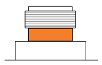
Port C

2.4-GHz and 5-GHz antenna

Orange band

5

2.5G mGig PD (PoE-IN) Ethernet port

If the port is not used, do not remove the covering plug. Otherwise, it might lead to water leaking into the AP.

3

Reset button (covered with a cap)

6

Port D

2.4-GHz and 5-GHz + SIA antenna

Purple band

Connectors and Ports on the Sides

Figure 3. Right–Side Connectors

1

Grounding Pad

Supported External Antennas

The CW9163E AP supports a combination of 2.4-GHz, 5-GHz, and 6-GHz SIA, depending on the port they are installed on.

The supported Cisco Antennas are:

  • CW-ANT-O1-NS-00

  • CW-ANT-D1-NS-00

  • CW-ANT-GPS2-S-00


Note


The AP operates with supported Cisco antennas only on all ports.

The following table lists the CW9163E AP supporting external antennas:

1

Port B

Supports 6-GHz band

4

Port C

Supports 2.4-GHz and 5-GHz bands

2

Port A

Supports 6-GHz band, SIA

5

Port 5

L1/L5 Band

3

Port D

Supports 2.4-GHz and 5-GHz bands, SIA

Table 1. CW9163E Access Point Supported 6-GHz External Antennas

PID

2.4–GHz Antenna Gain (dBi)

5–GHz Antenna Gain (dBi)

6–GHz Antenna Gain (dBi)

Antenna Type

CW-ANT-O1-NS-00

4

8

8

Direct Attach Omni Directional Antenna, Tri-band

CW-ANT-D1-NS-00

8

9

9

Wall or Pole Attach Wide-beam Directional Antenna, Tri-band

Table 2. CW9163E Access Point Supported External Antennas

PID

Antenna Gain (dBi)

Antenna Type

CW-ANT-GPS2-S-00

2

Wall or Pole Attach, AFC compliant, GNSS Antenna with 10-ft. integrated cable

For installation instructions and detailed information on any of these antennas, refer to the antenna guide at:

http://www.cisco.com/c/en/us/support/wireless/aironet-antennas-accessories/products-installation-guides-list.html

Use of Non-Cisco Antennas

RF connectivity and compliance of third-party antennas is the user’s responsibility. Cisco does not recommend any third-party antennas, and the Cisco Technical Assistance Center will not be able to provide any support for third-party antennas. Cisco’s FCC Part 15 compliance is only guaranteed with Cisco antennas or antennas that are of the same design and gain as Cisco antennas.

Power Sources

You can power the CW9163E AP with Power over Ethernet (PoE) and select power injectors. For more information, see Powering the Access Point.


Warning


Statement 1033—Safety Extra-Low Voltage (SELV)—IEC 60950/ES1–IEC 62368 DC Power Supply

To reduce the risk of electric shock, connect the unit to a DC power source that complies with the SELV requirements in IEC 60950-based safety standards or ES1 and PS1 requirements in IEC 62368-based safety standards or to a Class 2 power supply.


Caution


For PoE options and their corresponding modes of operation, see Table 1.

Caution


When the AP is installed outdoors or in a wet or damp location, the AC branch circuit powering the AP should be provided with ground fault protection (GFCI), as required by Article 210 of the National Electrical Code (NEC).

Power Injectors

CW9163E AP supports the following power injector models:

  • AIR-PWRINJ7=

  • AIR-PWRINJ6=

  • IW-PWRINJ-60RGDMG=

  • MA-INJ-6

  • MA-INJ-4


    Note


    The MA-INJ-4 power injector is at the End of Life (EOL) stage. Customers who already own these injectors may continue to use them with CW9163E AP.

Caution


When the AP is installed outdoors or in a wet or damp location, the AC branch circuit powering the AP should be provided with ground fault protection (GFCI), as required by Article 210 of the National Electrical Code (NEC).

Ethernet (PoE) Ports

The AP supports an Ethernet uplink port (also for PoE-In). The Ethernet uplink port on the AP uses an RJ-45 connector (with weatherproofing) to link the AP to the 100BASE-T, 1000BASE-T, or 2.5GBASE-T network. The Ethernet cable is used to send and receive Ethernet data and optionally supply inline power from the power injector or a suitably powered switch port.


Tip


The AP senses the Ethernet and power signals and automatically switches internal circuitry to match the cable connections.

The Ethernet cable must be a shielded, outdoor rated, Category 5e (CAT 5e) or better cable. The AP senses the Ethernet and power signals and automatically switches internal circuitry to match the cable connections.