Annex

This chapter contains general topics that may only apply to certain models of the Cisco Business switches.

Managing a Stack of Switches

Switches can either function on their own, or they can be connected into a stack of switches. By default, a device is always stackable, but has no stack port. All ports on the switches are network ports by default. You can look at a switch without any stack port as the active unit in a stack of only itself. You can also look at a switch without any stack port as a standalone switch. To stack two or more devices, reconfigure the desired network ports as stack ports in the switches and connect the switches with the resulting stack ports in a ring or chain topology.

The switches (units) in a stack are connected through stack ports. These switches are then collectively managed as a single logical switch. In some cases, stack ports can become members in Link Aggregation Groups (LAGs) increasing the bandwidth of the stack port.

The stack is based on a model of a single active/standby and multiple members. A stack provides the following benefits:

  • Network capacity can be expanded or contracted dynamically. By adding a unit, the administrator can dynamically increase the number of ports in the stack while maintaining a single point of management. Similarly, units can be removed to decrease network capacity.

  • The stacked system supports redundancy in the following ways:

    • The standby unit becomes the active of the stack if the original active fails.

    • The stack system supports two types of topologies: chain and ring. In ring topology, if one of the stack ports fails, the stack continues to function in chain topology.

    • A process known as Fast Stack Link Failover is supported on the ports in a ring stack to reduce the duration of data packet loss when one of the stack ports link fails. Until the stack recovers to the new chain topology, a stack unit loops back the packets that are supposed to be sent through its failed stacking port, and transmits the looped back packets through its remaining stacking port to the destinations. During Fast Stack Link failover, the active/standby units remain active and functioning.

Types of Units in Stack

A stack consists of a maximum of eight units. A unit in a stack is one of the following types:

  • Active—The active unit’s ID must be either 1 or 2. The stack is managed through the active unit that manages itself, the stand by unit and the member units.

  • Stand by—If the active unit fails, the stand by unit assumes the active role(switchover). The stand by unit’s ID must be either 1 or 2.

  • Member—These units are managed by the active unit.

In order for a group of units to function as a stack, there must be an active-enabled unit. When the active-enabled unit fails, the stack continues to function as long as there is a stand by unit (the main unit that assumes the active role).If the stand by unit fails, in addition to the active unit, and the only functioning units are the member units. These also stop functioning after one minute. This means for example, that if after 1 minute, you plug in a cable to one of the member units that was running without an active, the link will not come up.

Backward Compatibility of Number of Units in Stack

The stackable switches support anywhere from four units to eight units. This varies based on the switch model. Upgrading from and earlier software release can be done without changing the configuration files. When a firmware version, which does not support the hybrid stack modes is loaded to the stack and the stack is rebooted, the stack reverts to Native Stack mode. When a device in Hybrid stack mode is loaded with a firmware version that does not support Hybrid stack mode, its system mode reverts to the default system mode. If a stack’s unit IDs were manually-configured, those units whose ID is greater than 4 are switched to auto numbering.

Stack Topology

The units in a stack can be connected in one of the following types of topologies:

  • Chain Topology—Each unit is connected to the neighboring unit, but there is no cable connection between the first and last unit.

  • Ring Topology—Each unit is connected to the neighboring unit. The last unit is connected to the first unit. The following shows a ring topology of an eight-unit stack:

A ring topology is more reliable than a chain topology. The failure of one link in a ring does not affect the function of the stack, whereas the failure of one link in a chain connection might cause the stack to be split.

Topology Discovery

A stack is established by a process called topology discovery. This process is triggered by a change in the up/down status of a stack port. The following are examples of events that trigger this process:

  • Changing the stack topology from a ring to a chain

  • Merging two stacks into a single stack

  • Splitting the stack

  • Inserting other member units to the stack, for instance because the units previously disconnected from the stack due to a failure. This can happen in a chain topology if a unit in the middle of the stack fails.

During topology discovery, each unit in a stack exchanges packets, which contain topology information. After the topology discovery process is completed, each unit contains the stack mapping information of all units in the stack.

Unit ID Assignment

After topology discovery is completed, each unit in a stack is assigned a unique unit ID. The unit ID is set in the System Mode and Stack Management page in one of the following ways:

  • Automatically (Auto) —The Unit ID is assigned by the topology discovery process. This is the default setting.

  • Manually—The unit ID is manually set to an integer from 1-8.

Duplicate Unit IDs

If you assign the same unit ID to two separate units, only one of them can join the stack with that unit ID. If auto numbering has been selected, the duplicate unit is assigned a new unit number. If auto numbering was not selected, the duplicate unit is shut down. The following shows a case where two units were manually assigned the same unit ID. Unit 1 does not join the stack and is shut down. It did not win the active selection process between the active-enabled units (1 or 2).

Duplicate Unit Shut Down

Active Selection Process

The active unit is selected from the active-enabled units (1 or 2). The factors in selecting the active unit are taken into account in the following priority:

  • Force Active—If Force Active is activated on a unit, it is selected.

  • System Up Time—The active-enabled units exchange up-time, which is measured in segments of 10 minutes. The unit with the higher number of segments is selected. If both units have the same number of time segments,and the unit ID of one of the units was set manually while the other unit’s unit ID was set automatically, the unit with the manually-defined unit ID is selected; otherwise the unit with the lowest unit ID is selected. If both units IDs are the same, the unit with the lowest MAC address is chosen.


    Note


    The up time of the stand by unit is retained when it is selected as active in the switch failover process.


  • Unit ID—If both units have the same number of time segments, the unit with the lowest unit ID is selected.

  • MAC Address—If both units IDs are the same, the unit with the lowest MAC address is chosen.


Note


For a stack to operate, it must have an active unit. An active unit is defined as the main unit that assumes the active role. The stack must contain a unit 1 and/or unit 2 after the active selection process. Otherwise, the stack and all its units are partially shut down, not as a complete power-off, but with traffic-passing capabilities halted


Stack Changes

This section describes various events that can cause a change to the stack. A stack topology changes when one of the following occurs:

  • One or more units are connecting and/or disconnecting to and from the stack.

  • Any of its stack ports has a link up or down.

  • The stack changes between ring and chain formation.

When units are added or removed to and from a stack, it triggers topology changes, master election process, and/or unit ID assignment.

Connecting a New Unit

When a unit is inserted into the stack, a stack topology change is triggered. The unit ID is assigned (in case of auto numbering), and the unit is configured by the active unit.

One of the following cases can occur when connecting a new unit to an existing stack:

  • No duplicate unit IDs exist.

    • Units with user-defined IDs retain their unit ID.

    • Units with automatically-assigned IDs retain their unit ID.

    • Factory default units receive unit IDs automatically, beginning from the lowest available ID.

  • One or more duplicate unit IDs exist. Auto numbering resolves conflicts and assigns unit IDs. In case of manual numbering, only one unit retains its unit ID and the other(s) are shutdown.

  • The number of units in the stack exceeds the maximum number of units allowed. The new units that joined the stack are shut down, and a SYSLOG message is generated and appears on the master unit

The following shows an example of auto numbering when an active-enabled unit joins the stack. There are two units with unit ID = 1. The active selection process selects the best unit to be the active unit. The best unit is the unit with the higher uptime in segments of 10 minutes. The other unit is made the backup

Auto-numbered Active-enabled Unit

The following shows an example of auto numbering when a new unit joins thes tack. The existing units retain their ID. The new unit receives the lowest available ID.

Auto Number Unit

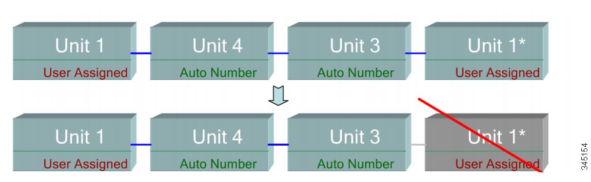
The following shows what happens when a user-assigned, active-enabled unit with Unit ID 1 joins a stack that already has an active unit with user-assigned unit ID1. The newer Unit 1 does not join the stack and is shutdown.

User-assigned Active-enabled Unit

Unit Failure in Stack

If the active unit fails, then the standby unit will take over the primary role and continues to operate the stack normally.

For the standby switch to be able to take the place of the active switch, both units remain on reserve at all times. When on reserve mode, the active switch and its standby switches are synchronized with a static configuration (contained in both the Startup and Running configuration files). The standby switch configuration file remains on the previous active switch.

Dynamic process-state information, such as the STP state table, dynamically-learned MAC addresses, dynamically-learned Smartport types, MAC Multicast tables, LACP, and GVRP are not synchronized. When an active switch is being configured, it synchronizes with the standby unit immediately. Synchronization is performed as soon as a command is executed. This is transparent.

When an active switch is being configured, it synchronizes the backup immediately. Synchronization is performed as soon as a command is executed. This is transparent.

If a unit is inserted into a running stack, and is selected as a standby unit, the active switch synchronizes it so that it has an up-to date configuration, and then generates a SYNC COMPLETE SYSLOG message. This is a unique SYSLOG message that appears only when standby is converging with the active unit, and looks like this: %DSYNCH-I-SYNCH_SUCCEEDED: Synchronization with unit 2 is finished successfully.

Active / Standby Switchover

When a active switch fails on the stack, a switchover occurs. The standby unit becomes the active, and all of its processes and protocol stacks are initialized to take responsibility for the entire stack. As a result, there is temporarily no traffic forwarding in this unit, but member units remain active.


Note


When STP is used and the ports are in link up, the STP port’s state is temporarily Blocking, and it cannot forward traffic or learn MAC addresses. This is to prevent spanning tree loops between active units.


Member Unit Handling

While the standby unit becomes the active switch, the member units remain active and continue to forward packets based on the configuration from the original active switch. This minimizes data traffic interruption in units. After the standby unit has completed the transition to the active state, it initializes the member units one at a time by performing the following operations:

  • Clear and reset the configuration of the member unit to default (to prevent an incorrect configuration from the new active unit). As a result, there is no traffic forwarding on the member unit.

  • Apply related user configurations to the member unit.

  • Exchange dynamic information such as port STP state, dynamic MAC addresses, and link up/down status between the new active and member unit. Packet forwarding on the member unit resumes after the state of its ports are set to forwarding by the active switch according to STP.


    Note


    Packet flooding to unknown Unicast MAC addresses occurs until the MAC addresses are learned or relearned.


Reconnecting the Original Active Unit after Failover

After failover, if the original active switch is connected again, the active selection process is performed. If the original active switch (unit 1) is reselected to be the active unit, the current active switch (unit 2, which was the original backup unit) is rebooted and becomes the backup once again.


Note


During active unit failover, the uptime of the standby unit is retained.


Software Auto Synchronization in a Stack

All units in the stack must run the same software version (firmware and boot code). Each unit in a stack automatically downloads firmware and boot code from the active unit if the firmware and/or boot code that the unit and the active are running is different. The unit automatically reboots itself to run the new version.

Stack Ports

All ports on the device are network (uplink) ports by default. To connect units, you must change the types of the ports to be used to connect the devices as stack ports. These ports are used to transfer data and protocol packets among the units

Stack Port Link Aggregation

When two neighboring units are connected, the stack ports connecting them are automatically assigned to a stack LAG. This feature enables increasing the stack bandwidth of the stack port beyond that of a single port. There can be up to two stack LAGs per unit.

The stack LAG can be composed of between two and up to the maximum number of stack ports depending on the unit type.

Stack Port States

Stack ports can be in one of the following states:

  • Down—Port operational status is down or stack port operational status is up, but traffic cannot pass on the port.

  • Active—Stack port was added to a stack LAG whose stack port operational status is up and traffic can pass on the port and it is a member of a stack LAG.

  • Standby—Stack port operational status is up and bidirectional traffic can pass on the port, but the port cannot be added to a stack LAG, and the port does not transmit traffic. Possible reasons for a port being in standby are:

    • Stack ports with different speeds are used to connect a single neighbor.

Backwards Compatibility

The following modes have been expanded in the current software version of the device. Care must be taken when using these features in previous software versions:

  • Stack Port LAG—If a unit whose software supports stack ports in LAGs is connected to a unit whose software does not support stack ports in LAGs, the stack port connecting the units is not made a member of the stack LAG. The units are connected through the stack ports, and the active stack unit copies its software to the other unit. The software copied depends on the unit which becomes the active unit.

  • Queues Mode—This mode can be changed from 4 QoS queues to 8 QoS queues. There is no issue when upgrading from previous software versions that did not support 8 queues, since the 4-queue mode is the default queues mode in the current software version. However, when changing the queues mode to 8 queues, the configuration must be examined and adjusted to meet the desired QoS objectives with the new queues mode. Changing the queues mode takes effect after rebooting the system. Queue-related configuration that conflicts with the new queues mode is rejected.

  • Stacking Mode—The Stacking mode has been expanded to include hybrid stacking modes. There is no problem in upgrading from previous software versions, since the device will boot with the existing stacking mode (Native Stacking mode). If you want to downgrade software from a device that was configured in a hybrid stacking mode to a software version that does not support hybrid stacking, configure the device to Native Stacking mode first.

Physical Constraints for Stack LAGs

  • A stack LAG must contain ports of the same speed.

  • When attempting to connect a unit to a stack whose topology is not a ring/chain (for example, trying to connect a unit to more than two neighboring units - star topology), only two stack LAGs can be active, the remainder of the stack ports are set to standby mode (inactive).

Auto Selection of Port Speed

The stacking cable type is discovered automatically when the cable is connected to the port (auto-discovery is the default setting). The system automatically identifies the stack cable type and selects the highest speed supported by the cable and the port.

A SYSLOG message (informational level) is displayed when the cable type is not recognized.

Link Aggregation

Overview

Link Aggregation Control Protocol (LACP) is part of the IEEE specification (802.3az) that enables you to bundle several physical ports together to form a single logical channel (LAG). LAGs multiply the bandwidth, increase port flexibility, and provide link redundancy between two devices. Link aggregation allows you combine multiple Ethernet links to a single link between two network devices. The most common combinations involve connecting a switch to another switch, a server, a network attached storage (NAS) device, or a multiport WiFi access point.

Network devices and management functions treat the link aggregation group (LAG) of multiple Ethernet connections as a single link. For example, you can include a LAG in a virtual local area network (VLAN). You can also configure more than one LAG on the same switch, or add more than two Ethernet links to the same LAG (the maximum number of links per LAG depends on your device).

Some network devices support Link Aggregation Control Protocol (LACP), which helps to prevent errors in the link aggregation setup process.

Link Aggregation Benefits

Link Aggregation offers the following benefits:

  • Increased reliability and availability- If one of the physical links in the LAG goes down, traffic reassigned to another physical links.

  • Better use of physical resources- Traffic can be load-balanced across the physical links.

  • Increased bandwidth- The aggregated physical links deliver higher bandwidth than each individual link.

  • Cost effectiveness- A physical network upgrade can be expensive, especially if it requires new cable runs. Link aggregation increases bandwidth without requiring new equipment.

Link Aggregation Set Up

The following instructions describe in general terms how to set up link aggregation between two devices in your network.

Procedure


Step 1

Make sure that both devices support link aggregation.

Step 2

Configure the LAG on each of the two devices.

Step 3

Make sure that the LAG that you create on each device has the same settings for port speed, duplex mode, flow control, and MTU size.

Step 4

Make sure that all ports that are members of a LAG have the same virtual local area network (VLAN) memberships. If you want to add a LAG to a VLAN, set up the LAG first and then add the LAG to the VLAN; do not add individual ports.

Warning


Do not connect the devices to each other using more than one Ethernet cable until after you set up the LAG on each device. If you form multiple connections between the two devices and neither device has loop prevention, you create a network loop. Network loops can slow or stop normal traffic on your network.

Step 5

Note the ports on each device to which you add the LAG, and make sure that you connect to the correct ones. The LAG issues an alert and rejects the configuration if the port members have different settings for port speed, duplex mode, or MTU size, or if you accidentally connect ports that are not members of the LAG.

Step 6

Use Ethernet or fiber cable to connect the ports that you added to the LAG on each device.

Step 7

Verify that the port LED for each connected port on each switch is blinking green.

Step 8

Verify in the admin interface for each device that the link is up.


Configure LAG Load Balance

Procedure


Step 1

Log in to the Cisco switch by entering the Username and Password. Click Log In. By default the username and password are cisco, but since you are working on an existing network, you should have your own username and password. Enter those credentials instead.

Step 2

Navigate to Port Management > LAG Management and select the Load Balance Algorithm option. You can select either MAC Address, or IP/MAC Address. Click Apply.

Note


By default, MAC Address is the option selected for Load Balance Algorithm.

Step 3

Next, the Success notification should appear on the screen. Click File Operations to save the configuration on the switch to startup configuration.

Step 4

The File Operations page will open. Verify that the Source File Name is selected as Running Configuration and Destination File Name is selected as Startup Configuration. Click Apply to save the configuration.


UDLD

Overview

Unidirectional Link Detection (UDLD) is a Layer 2-protocol that enables devices connected through fiber-optic or twisted-pair Ethernet cables to detect unidirectional links. A unidirectional link occurs whenever traffic from a neighboring device is received by the local device, but traffic from the local device is not received by the neighbor.

The purpose of UDLD is to detect ports on which the neighbor does not receive traffic from the local device (unidirectional link) and to shut down those ports. All connected devices must support UDLD for the protocol to successfully detect unidirectional links. If only the local device supports UDLD, it is not possible for the device to detect the status of the link. In this case, the status of the link is set to undetermined. The user can configure whether ports in the undetermined state are shut down or merely trigger notifications.

How UDLD Works

When UDLD is enabled on a port, the following actions are performed:

  • UDLD initiates the detection state on the port.

    • In this state, UDLD periodically sends messages on every active interface to all neighbors. These messages contain the device ID of all known neighbors. It sends these messages according to a user-defined message time.

  • UDLD receives UDLD messages from neighboring devices. It caches these messages until the expiration time (3 times message time) has passed. If a new message is received before the expiration time, the information in that message replaces the previous one.

  • When the expiration time expires, the device does the following with the information received:

    • If the neighbor message contains the local device ID—The link status of the port is set to bidirectional.

    • If the neighbor message does not contain the local device ID—The link status of the port is set to unidirectional, and the port is shut down.

  • If UDLD messages are not received from a neighboring device during the expiration time frame, the link status of the port is sent to undetermined and the following occurs:

    • Device is in normal UDLD mode: A notification is issued.

    • Device is in aggressive UDLD mode. The port is shut down.

While the interface is in the bidirectional or the undetermined state, the device periodically sends a message each message time seconds. The above steps are performed over and over.

Usage Guidelines

Cisco does not recommend enabling UDLD on ports that are connected to devices on which UDLD is not supported or disabled. Sending UDLD packets on a port connected to a device that does not support UDLD causes more traffic on the port without providing benefits.

In addition, consider the following when configuring UDLD:

  • Set the message time according to how urgent it is to shut down ports with a unidirectional link. The lower the message time, the more UDLD packets are sent and analyzed, but the sooner the port is shut down if the link is unidirectional.

  • If you want UDLD to be enabled on a copper port, you must enable it per port. When you globally enable UDLD, it is only enabled on fiber ports.

  • Set the UDLD mode to normal when you do not want to shut down ports unless it is known for sure that the link is unidirectional.

  • Set the UDLD mode to aggressive when you want both unidirectional and bidirectional link loss.

Smartport Overview

The Smartport feature provides a convenient way to save and share common configurations. By applying the same Smartport macro to multiple interfaces, the interfaces share a common set of configurations. A Smartport macro is a script of CLI (Command Line Interface) commands

A Smartport macro can be applied to an interface by the macro name, or by the Smartport type associated with the macro. Applying a Smartport macro by macro name can be done only through CLI.

There are two ways to apply a Smartport macro by Smartport type to an interface:

  • Static Smartport—You manually assign a Smartport type to an interface. The result is the corresponding Smartport macro is applied to the interface.

  • Auto Smartport—Auto Smartport waits for a device to be attached to the interface before applying a configuration. When a device is detected from an interface, the Smartport macro (if assigned) that corresponds to the Smartport type of the attaching device is automatically applied.

A Smartport is an interface to which a built-in (or user-defined) macro may be applied. These macros are designed to provide a means of quickly configuring the device to support the communication requirements and utilize the features of various types of network devices. The network access and QoS requirements vary if the interface is connected to an IP phone, a printer, or a router and/or Access Point (AP).

VLAN Description

Each VLAN is assigned a VLAN ID (VID) with a value ranging from 1 to 4094. A VLAN member is a port on a device in a bridged network that may send and receive data from the VLAN. If all packets headed for that port into the VLAN have no VLAN tag, the port is an untagged member of the VLAN. If all packets headed for that port into the VLAN include a VLAN tag, that port is a tagged member of the VLAN. A port can only belong to one untagged VLAN, although it can belong to several tagged VLANs.

In VLAN Access mode, a port can only belong to one VLAN. The port can be part of one or more VLANs if it is in General or Trunk mode. VLANs are used to solve security and scalability problems. VLAN traffic stays within the VLAN and is terminated at VLAN devices. It also simplifies network configuration by conceptually linking devices without requiring them to be physically relocated.

A four-byte VLAN tag is applied to each Ethernet frame if it is VLAN-tagged. The tag comprises a VLAN ID ranging from 1 to 4094, as well as a VLAN Priority Tag (VPT) ranging from 0 to 7 When a frame enters a VLAN-aware device, the four-byte VLAN tag in the frame is used to classify it as belonging to a VLAN. The frame is classified to the VLAN based on the PVID (Port VLAN Identifier) defined at the ingress port where the frame is received if there is no VLAN tag in the frame or if the packet is merely priority-tagged. If Ingress Filtering is enabled and the ingress port is not a member of the VLAN to which the packet belongs, the frame is dropped at the ingress port. Only if the VID in the VLAN tag is 0 is a frame considered priority-tagged. Frames that belong to a VLAN stay in the VLAN.

This is accomplished by transmitting or forwarding a frame only to members of the target VLAN's egress ports. A VLAN's egress port can be either tagged or untagged.

The egress port's role is as follows:

  • If the egress port is a tagged member of the target VLAN and the original frame does not include a VLAN tag, the egress port adds a VLAN tag to the frame.

  • If the egress port is an untagged member of the target VLAN and the original frame has a VLAN tag, the VLAN tag is removed from the frame.

VLAN Roles

Layer 2 is where VLANs work. All VLAN traffic (Unicast, Broadcast, and Multicast) is contained within the VLAN. Over the Ethernet MAC layer, devices connected to separate VLANs do not have direct connectivity. Only Layer 3 routers allow devices from different VLANs to interact with one another. If each VLAN represents an IP subnet, an IP router is necessary to route IP traffic between them.

The IP router could be a standard router with only one VLAN connected to each of its ports. VLAN untagged traffic to and from a standard IP router is required. Each of the IP router's interfaces can connect to one or more VLANs, making it a VLAN-aware IP router. Traffic to and from a VLAN-aware IP router can be VLAN tagged or untagged.

Generic VLAN Registration Protocol is used by adjacent VLAN-aware devices to communicate VLAN information (GVRP). VLAN information is thus conveyed across a bridged network. Based on the GVRP information exchanged by devices, VLANs can be formed statically or dynamically on a device. A VLAN can be static or dynamic (thanks to the GVRP), but not both at the same time. Refer to the GVRP Settings section for further information about GVRP.

QinQ

QinQ provides isolation between service provider networks and customers' networks. The device is a provider bridge that supports port-based c-tagged service interface.

With QinQ, the device adds an ID tag known as Service Tag (S-tag) to forward packets into the provider network. The S-tag is used to segregate traffic between various customers, while preserving the customer VLAN tags.

Customer traffic is encapsulated with an S-tag with TPID 0x8100, regardless of whether it was originally c-tagged or untagged. The S-tag enables this traffic to be treated as an aggregate within a provider bridge network, where the bridging is based on the S-tag VID (S-VID) only.

The S-Tag is preserved while traffic is forwarded through the network service provider's infrastructure, and is later removed by an egress device.

An additional benefit of QinQ is that there is no need to configure customers' edge devices.

Private VLAN

The Private VLAN feature provides layer-2 isolation between ports. This means that at the level of bridging traffic, as opposed to IP routing, ports that share the same Broadcast domain cannot communicate with each other. The ports in a private VLAN can be located anywhere in the layer 2 network, meaning that they do not have to be on the same switch. The private VLAN is designed to receive untagged or priority-tagged traffic and transmit untagged traffic.

The following types of ports can be members in a private VLAN:

  • Promiscuous—A promiscuous port can communicate with all ports of the same private VLAN. These ports connect servers and routers.

  • Community (host)—Community ports can define a group of ports that are member in the same Layer 2 domain. They are isolated at Layer 2 from other communities and from isolated ports. These ports connect host ports.

  • Isolated (host)—An isolated port has complete Layer 2 isolation from the other isolated and community ports within the same private VLAN. These ports connect host ports.

The following types of private VLANs exist:

  • Primary VLAN—The primary VLAN is used to enable Layer 2 connectivity from promiscuous ports to isolated and to community ports. There can only be a single primary VLAN per private VLAN.

  • Isolated VLAN (also known as a Secondary VLAN)—An isolated VLAN is used to enable isolated ports to send traffic to the primary VLAN. There can only be a single, isolated VLAN per private VLAN.

  • Community VLAN (also known as a Secondary VLAN)—To create a sub-group of ports (community) within a VLAN, the ports must be added a community VLAN. The community VLAN is used to enable Layer 2 connectivity from community ports to promiscuous ports and to community ports of the same community. There can be a single community VLAN for each community and multiple community VLANs can coexist in the system for the same private VLAN).

Host traffic is sent on isolated and community VLANs, while server and router traffic is sent on the primary VLAN.

Shared MAC address learning exists between all the VLANs that are members in the same private VLAN (although the switch supports independent VLAN learning). This enables Unicast traffic, despite the fact that host MAC addresses are learned by isolated and community VLANs, while routers and server MAC addresses are learned by the primary VLAN.

A private VLAN-port can only be added to one private VLAN. Other port types, such as access or trunk ports, can be added to the individual VLANs that make up the private VLAN (since they are regular 802.1Q VLANs).

A private VLAN can be configured to span across multiple switches by setting inter-switch ports as trunk ports and adding them to all VLANs in the private VLAN. Inter-switch trunk ports send and receive tagged traffic of the private VLAN’s various VLANs (primary, isolated and the communities).

Configure a VLAN on a Switch

Virtual Local Area Network (VLAN) creation allows you to make separate broadcast domains on a switch. The broadcast domains can associate with one another with the help of a Layer 3 device such as a router. A VLAN is mainly used to form groups among the hosts regardless of where the hosts are physically located. Thus, a VLAN improves security with the help of group formation among the hosts. When a VLAN is created, it has no effect until that VLAN is attached to at least one port either manually or dynamically. One of the most common reasons to set up a VLAN is to set up a separate VLAN for voice, and a separate VLAN for data. This directs the packets for both types of data despite using the same network.

Create a VLAN

Procedure


Step 1

Log in to the web-based utility and choose VLAN Management > VLAN Settings.

Step 2

Under the VLAN Table area, click Add to create a new VLAN.

Step 3

VLAN can be added in two different methods as shown by the options below. Choose a radio button that corresponds to the desired method:

  • VLAN — Use this method to create a specific VLAN.

  • Range — Use this method to create a range VLANs.

Step 4

If you chose VLAN in Step 3, enter the VLAN ID in the VLAN ID field. The range must be between 2 to 4094.

Step 5

In the VLAN Name field, enter a name for the VLAN. For this example, the VLAN Name will be Accounting. Up to 32 characters may be used.

Step 6

Check the VLAN Interface State check box to enable the VLAN interface state; it is already checked by default. If not, the VLAN will be effectively shut down, and nothing will be able to be transmitted or received through the VLAN.

Step 7

Check the Link Status SNMP Traps check box if you want to enable the generation of SNMP traps. This is enabled by default.

Step 8

If you chose Range in Step 3, enter the range of the VLANs in the VLAN Range field. The available range is 2–4094. For this example, the VLAN Range is from 3 to 52.

Note


Up to 100 VLANs can be created at a time.

Step 9

Click Apply.


GVRP Configuration

GVRP is supported only on COS switches. GVRP will run only on 802.1Q trunk ports and is used primarily to prune traffic from VLANs that does not need to be passed between trunking switches. Use the following steps to configure GVRP. To ensure that port remains in General mode it is strongly advised to disable smartport macro auto on each interface participating in GVRP.

Procedure


Step 1

Configure the switch with the desired VLANs. For example, you can configure the following settings:

  • Switch 1 can be assigned a VLAN ID of 1 as the default, then 300, 400 and 500.

  • Switch 2 can be assigned a VLAN ID of 1 as the default.

  • Switch 3 can be assigned a VLAN ID of 1 as the default, then 100 and 200.

Step 2

To enable GVRP on an interface, it must be configured in General Mode, otherwise the switch will not send any GARP messages.

Step 3

Enable GVRP globally. By default GVRP is not enabled for the switch. You must first enable GVRP on the switch before you can configure the 802.1Q ports for GVRP operation.

Step 4

Configure the port for 802.1Q operation. GVRP will run only on ports that are configured for 802.1Q trunking.

Step 5

Configure the port GVRP. GVRP must be configured on both sides of the trunk to work correctly.

Step 6

(Optional) Configure the port registration mode. By default GVRP ports are in normal registration mode. These ports use GVRP join messages from neighboring switches to prune the VLANs running across the 802.1Q trunk link. If the device on the other side is not capable of sending GVRP messages, or if you do not want to allow the switch to prune any of the VLANs, use the fixed mode. Fixed mode ports will forward for all VLANs that exist in the switch database. Ports in forbidden mode forward only for VLAN 1.


Voice VLAN Configuration

This troubleshooting tip is for Voice VLAN configuration.

Procedure


Step 1

Create a VLAN on the switch. For example, if the data VLAN is set at 2 and the Voice VLAN is set at 5, then assign VLAN 5 in the Auto Voice VLAN tab.

Step 2

Make sure that you see the operational Voice VLAN set to 5.

Step 3

Change Display Mode from Basic to Advanced.

Step 4

Next, in the Interface Settings under VLAN Management, change the port mode from Access to Trunk.

Step 5

Next, under Port to VLAN Membership, set the data VLAN as untagged and Voice VLAN as tagged on the port that is connected to the IP phones. Do the same for the desktops and laptops that are connected to the IP phones.

Step 6

Go to IP configuration > IPv4 Interface and assign an IP to both VLAN 2 and VLAN 5.

Step 7

Create a DHCP pool for both VLANs just in case the DHCP server is enabled on the device. (Optional)

Step 8

Go to Smart port tab, make sure Smart port is enabled.

Step 9

Make sure IP Phone+Desktop is checked under Device Detection.

Step 10

Go to Smartport Type settings and select Macro for IP Phone+Desktop.

Step 11

Click on Edit. Make sure Macro Type is selected as Built-in Macro.

Step 12

Change Macro Parameters.

  • Change the Parameter2 value to the value of Data VLAN ID (in this case 2 as data VLAN is 2).

  • Parameter3 value will automatically show 5 in case you see the operational voice VLAN as 5 under Auto voice VLAN settings.

Step 13

Save the running configuration to start up configuration.


Delete a Voice VLAN


Note


If you run into an instance where you are not able to delete the voice VLAN and getting an error message: “VLAN xxx cannot be deleted because it is used as the agreed Voice VLAN”, this is because of a behavior of the Voice VLAN. By default, our switches are configured with “triggered auto voice VLAN” option set to enable on any firmware 2.5.5.x and lower. Once the switch receives the VSDP packets from other switch or CDP packets from UC router, the voice VLAN is automatically enabled.


If you want to delete the Voice VLAN for one reason or the other, you will need to follow a sequence of steps for it to succeed. Via the GUI, here what you can do:

Procedure

Step 1

Select VLAN Management > Voice VLAN > Properties, and set Dynamic Voice VLAN to Disable.

Step 2

In VLAN Management > Voice VLAN > Properties, and set Voice VLAN Id to 1 (this is to remove the Voice ID that is being used in the setup and set the value to default 1).

Step 3

Return back to VLAN Management > VLAN Settings and delete the VLAN that was being used as the Voice VLAN

Note


However, that if you re-enable Dynamic Voice VLAN, the VLAN you removed will automatically be re-created and set as Voice VLAN.


Troubleshooting Link Flapping

This troubleshooting tip will help to resolve link flapping issues in the Cisco Business switches.


Note


Whenever link flapping occurs between switches that are either stacked or there is an uplink with the another switch; follow the steps below to get the issue resolved.


Procedure


Step 1

Make sure that both switches are upgraded to the latest firmware version and that both switches are running the same firmware.

Step 2

Disable the Discovery-Bonjour Protocol by clicking Administration > Discovery-Bonjour > Disable.

Step 3

Disable EEE (Energy Efficient Ethernet) on both the switches, by clicking Port Management>Green ethernet>Properties> 802.3 Energy Efficient Ethernet (EEE)> Disable.

Step 4

Enable Link Flap Prevention in both the switches by clicking on Port Management>Error Recovery.Next, check Enable in Link Flap Prevention to enable.

Step 5

Disable LLDP if issue persists after the Steps 1 to 4. Click Administration > Discovery-LLDP Properties > LLDP Status > Disable).


If Steps 1 to 5 do not help to resolve the link flapping, then remove all port on the port used for uplink/stacking.

Important: In case stacking is configured then you must remove the ports from stacking and configure them again.

Identifying Link Flapping

A link flap occurs when a physical interface on the switch continually goes up and down, three or more times a second for duration of at least ten seconds. The common cause is usually related to bad, unsupported, or non-standard cable or Small Form-Factor Pluggable (SFP) or related to other link synchronization issues. The cause for link flapping can be intermittent or permanent.

Since link flapping tends to be a physical interference, this section explains the steps that can be taken to diagnose and prevent it.

Procedure


Step 1

Try changing cables and monitor. If the issue persists, proceed to Step 2

Step 2

Go to Status and Statistics > Diagnostics > Copper Test.

Step 3

Select the Port from the drop-down menu and click on Copper Test.

Step 4

A warning will appear. Be aware that the port will be shut down for a short period of time. Choose OK.

Step 5

The Test Results will be displayed. If it says OK, it is most likely not the cable. If the results are not OK, change the cable and repeat the copper test to confirm that it is not the cable.

Analyzing your Topology

To confirm it is a physical problem and not a configuration issue on the switch, you need to analyze the devices connected to your switch. Check the following:

  1. What devices are connected to the switch?

    • Analyze each device connected to the switch. Have you experienced any issues with those devices?

  2. Which ports are causing the problem and which devices are connected to those ports?

    • Test the ports by connecting other devices and verifying if the problem continues.

    • See if the device is causing issues on another port.

  3. Is it the port or the device?

    • Determining whether it is the port, or the device determines how to continue the troubleshooting process.

    • If it is the device, you may have to contact support management for that device.

    • If you have determined it is the port, it is time to check whether the issue is related to configuration or a physical one.


Configure Link Flap Prevention

Link flap prevention minimizes the disruption to switch and network operations in a link flap situation. It stabilizes the network topology by automatically setting the ports that experience excessive link flap events to err-disable. This mechanism also provides time to debug and locate the root cause for the flapping. A Syslog message or Simple Network Management Protocol (SNMP) trap is sent to alert regarding link flap and port shutdown. The interface will become active again only if specifically enabled by you or your system administrator.

Procedure


Step 1

Log into your switch Web User Interface (UI).

Step 2

Change to Advanced Mode.

Step 3

Go to Port Management > Port Settings.

Step 4

Check the Enable box for Link Flap Prevention. Press Apply.

Step 5

Click on Save to save your configurations.


Spanning Tree Protocol

Spanning Tree Protocol (STP) is a Layer 2 link management protocol that provides path redundancy while preventing loops in the network. For a Layer 2 Ethernet network to function properly, only one active path can exist between any two stations. Multiple active paths among end stations cause loops in the network. If a loop exists in the network, end stations might receive duplicate messages.

The STP uses a spanning-tree algorithm to select one switch of a redundantly connected network as the root of the spanning tree. The algorithm calculates the best loop-free path through a switched Layer 2 network by assigning a role to each port based on the role of the port in the active topology:

  • Root—A forwarding port elected for the spanning-tree topology

  • Designated—A forwarding port elected for every switched LAN segment

  • Alternate—A blocked port providing an alternate path to the root bridge in the spanning tree

  • Backup—A blocked port in a loopback configuration

The switch that has all of its ports as the designated role or as the backup role is the root switch. The switch that has at least one of its ports in the designated role is called the designated switch.

STP provides a tree topology for any arrangement of switches and interconnecting links, by creating a unique path between end stations on a network, and thereby eliminating loops.

The device supports the following Spanning Tree Protocol versions:

  • Classic STP- Provides a single path between any two end stations, avoiding and eliminating loops.

  • Rapid STP (RSTP)- Detects network topologies to provide faster convergence of the spanning tree. This is most effective when the network topology is naturally tree-structured, and therefore faster convergence might be possible. RSTP is enabled by default.

  • Multiple STP (MSTP)- MSTP is based on RSTP. It detects Layer 2 loops, and attempts to mitigate them by preventing the involved port from transmitting traffic. Since loops exist on a per-Layer 2-domain basis, a situation can occur when a port is blocked to eliminate a STP loop. Traffic will be forwarded to the port that is not blocked, and no traffic will be forwarded to the port that is blocked. This is not an efficient usage of bandwidth as the blocked port will always be unused. MSTP solves this problem by enabling several STP instances, so that it is possible to detect and mitigate loops separately in each instance. This enables a port to be blocked for one or more STP instances but non blocked for other STP instances. If different VLANs are associated with different STP instances, then their traffic will be relayed based on the STP port state of their associated MST instances. Better bandwidth utilization results.

  • PVST+ /RPVST+ - (Rapid) Per VLAN Spanning Tree

    • PVST+ is a protocol that runs a separate instance of the 802.1Q STP standard protocol per VLAN

    • Rapid PVST+ is a protocol that runs a separate instance of the 802.1Q RSTP standard protocol per VLAN.

      As part of PVST/RPVST+ operation, a separate PVST frame is sent for each VLAN defined on a port. This enables maintaining state and topology per each VLAN

  • SSTP- Cisco switches use special Shared Spanning Tree Protocol (SSTP) Bridge Protocol Data Units (BPDUs) to exchange PVST+ and rapid PVST+ spanning tree topology information. They transmit SSTP BPDUs to the Cisco shared spanning tree MAC address 01-00-0C-CC-CC-CD. These BPDUs have a format based on a proprietary enhancement of IEEE standard 802.1Q. On the native VLAN, these BPDUs are untagged. When a port is configured in trunk mode with multiple VLANs, then it transmits the SSTP BPDUs on that port tagged for those VLANs.

Interoperation Between Spanning Tree Protocols

There are two main aspects to the interoperation of IEEE standard MSTP (including RSTP and STP) with PVST+ (and rapid PVST+). The first involves forming a common spanning tree between switches and regions running MSTP and PVST+. The second involves tunneling PVST+ spanning trees across MSTP regions.

When a Cisco switch configured with PVST+ receives IEEE standard RSTP BPDUs on a port, it recognizes them, and sends two versions of BPDUs on the port: SSTP format BPDUs and IEEE standard STP BPDUs. Similarly, a switch configured with rapid PVST+ recognizes IEEE standard RSTP BPDUs, and on any port that receives RSTP BPDUs, it sends two versions of BPDUs: SSTP format and IEEE standard RSTP format BPDUs.

There are differences between the ways that MSTP and PVST+ map spanning tree instances to VLANs: we know that PVST+ creates a spanning tree instance for every VLAN, whereas MSTP maps one or more VLANs to each MST instance. At the point where a PVST+ region meets an MSTP region, the set of PVST+ instances does not generally match the set of MST instances. Therefore, the PVST+ region and the MSTP region need to communicate with each other on a single common spanning tree instance.

Interoperation between an MSTP region and a PVST+ region via the Common Spanning Tree is achieved as follows.

MST and PVST+ both offer loop-free layer two topologies but they each use a different approach:

  • MST maps multiple VLANs to an instance, reducing the number of spanning-tree instances.

  • PVST+ calculates an instance for each spanning-tree instance.

PVST+ sends BPDUs for each instance/VLAN so you could let MST process each BPDU separately with the instance that is configured for the VLAN.

When an MST region is connected to a PVST+ topology, MST simulates PVST+ with a PVST simulation mechanism. The MST region will send PVST+ BPDUs (one for each VLAN) on the interfaces that are connected to PVST+ switches. These BPDUs all carry the same information and advertise the same root bridge. The interfaces that connect to the PVST+ topology are called boundary interfaces/ports. Since PVST+ switches now receive BPDUs for each VLAN from MST carrying the same information, they will all make the same decisions when selecting a root bridge, root port, etc.

It is easiest to configure your network so that the MST region is the root bridge in your network. If your PVST+ domain has the root bridge, then MST will use the same root port for all VLANs. If the root bridge is in your MST region, then you change the cost per VLAN on your PVST+ switches to use different root ports and use a bit of load balancing.

RSPAN Configuration

SPAN (Switch Port Analyzer), also known as port mirroring or port monitoring, selects network traffic for analysis by a network analyzer. A Cisco Switch Probe device or another Remote Monitoring (RMON) probe can be used as the network analyzer.

Port mirroring is a network device feature that sends a copy of network packets seen on a single device port, multiple device ports, or an entire Virtual Local Area Network (VLAN) to a network monitoring connection on another device port. This is commonly used for network appliances that require network traffic monitoring, such as intrusion detection systems. The data packets are processed by a network analyzer connected to the monitoring port for diagnosis, debugging, and performance monitoring.

The Remote Switch Port Analyzer (RSPAN) is a SPAN extension. RSPAN extends SPAN by allowing you to monitor multiple switches across your network and define the analyzer port on a remote switch. This means you'll be able to centralize your network capture devices.

RSPAN works by mirroring traffic from an RSPAN session's source ports onto a VLAN dedicated to the RSPAN session. This VLAN is then trunked to other switches, allowing RSPAN session traffic to traverse multiple switches. Traffic from the RSPAN session VLAN is simply mirrored out the destination port on the switch that contains the session's destination port.

The traffic for each RSPAN session is carried over a user-specified RSPAN VLAN that is dedicated for that RSPAN session in all participating switches. The traffic from the source interfaces on the start device is copied to the RSPAN VLAN through a reflector port. This is a physical port that has to be set. It is used exclusively to build an RSPAN session. The "network" keyword is required when specifying the reflector port, and non-RSPAN traffic is allowed over the link.

The reflector port has these characteristics:

  • It can be a physical port that is assigned to an EtherChannel group, even if the EtherChannel group is specified as a SPAN source. The port is removed from the group while it is configured as a reflector port.

  • A port used as a reflector port cannot be a SPAN source or destination port, nor can a port be a reflector port for more than one session at a time.

  • It is invisible to all VLANs.

  • Spanning tree is automatically disabled on a reflector port.

  • A reflector port receives copies of sent and received traffic for all monitored source ports.

RSPAN Traffic Flow

  • Each RSPAN session's traffic is routed over a user-specified RSPAN VLAN that is dedicated to that RSPAN session in all participating switches.

  • The traffic from the start device's source interfaces is copied to the RSPAN VLAN via a reflector port. This is a physical port that must be configured and requires a "network" keyword that allows other traffic over the link.

  • This reflector port serves as a mechanism for copying packets to an RSPAN VLAN.

  • RSPAN traffic is then routed through trunk ports on intermediate devices to the final switch's destination session.

  • The RSPAN VLAN is monitored by the destination switch and copied to a destination port.

RSPAN Port Membership Rules

  • On all switches — Membership in RSPAN VLAN can be tagged only.

  • Start Switch

    • SPAN source interfaces are not permitted to be members of the RSPAN VLAN.

    • Reflector port cannot be a member of this VLAN.

  • Intermediate Switch

    • It is recommended that RSPAN membership be removed from all ports that are not used to pass mirrored traffic.

    • An RSPAN VLAN typically has two ports.

  • Final Switch

    • Mirrored traffic requires that the source ports be members of the RSPAN VLAN.

    • RSPAN membership should be removed from all other ports, including the destination interface.

Multicast

Multicast offers an efficient communication mechanism for sending messages to multiple recipients in separate locations. It is also capable of supporting many-to-many and many-to-one communication.

Multicast applications use User Datagram Protocol (UDP) on IP. Messages are sent by a source (called the sender) and will send messages (termed as a stream) even if there is not another device on the network interested in receiving that information. Receivers, on the other hand, must subscribe to a particular multicast stream in order to inform the network to forward those messages.

IP multicasting is an efficient way to use network resources, especially for bandwidth-intensive services such as audio and video. IP multicast routing enables a host (source) to send packets to a group of hosts (receivers) anywhere within the IP network by using a special form of IP address called the IP multicast group address. The sending host inserts the multicast group address into the IP destination address field of the packet, and IP multicast routers and multilayer switches forward incoming IP multicast packets out all interfaces that lead to members of the multicast group. Any host, regardless of whether it is a member of a group, can send to a group. However, only the members of a group receive the message

Default IP Multicast Routing Configuration

This table displays the default IP multicast routing configuration.

Table 1. Default IP Multicast Routing Configuration

Feature

Default Settings

Multicast routing

Disabled on all interfaces.

Candidate BSRs

Disabled.

Candidate RPs

Disabled.

Shortest-path tree threshold rate

0 kb/s.

Understanding IGMP

Internet Group Management Protocol (IGMP) is a protocol designed for multicast purposes. With IGMP, you can establish group memberships between different users within a network. IGMP is mainly used for multimedia streaming, such as video-chat, between different users in a network. Snooping is the term used when a third party in a communication listens or observes the current connection data traffic. Therefore, IGMP Snooping is a process that listens specifically to multicast traffic. You can enable IGMP Snooping to forward multicast traffic to only already registered multicast clients on specific ports of the switch. This way, the multicast frames are only forwarded to a specific multicast client within a VLAN instead of to all the users in that VLAN.

Multicast is the network layer technique used to transmit data packets from one host to selected hosts in the network. At the lower layer, the switch broadcasts the multicast traffic on all ports, even if only one host needs to receive it. Internet Group Management Protocol (IGMP) snooping is used to forward Internet Protocol version 4 (IPv4) multicast traffic to the desired host. On the other hand, Multicast Listener Discovery (MLD) snooping is used to forward Internet Protocol version 6 (IPv6) multicast traffic to the desired hosts.

When IGMP is enabled, it detects the IGMP messages exchanged between the IPv4 router and the multicast hosts attached to the interfaces. It then maintains a table that restricts IPv4 multicast traffic and forwards them dynamically to the parts that need to receive them.

The following configurations are prerequisites for configuring IGMP.

  1. Configure Virtual Local Area Network (VLAN).

  2. Enable Bridge Multicast Filtering.

When MLD is enabled, it detects the MLD messages exchanged between the IPv6 router and the multicast hosts attached to the interfaces. It then maintains a table that restricts IPv6 multicast traffic and forwards them dynamically to the ports that need to receive them.

IGMP_MLD Proxy

IGMP/MLD Proxy is a simple IP Multicast protocol. Using IGMP/MLD Proxy to replicate Multicast traffic on devices like edge boxes can make the design and installation of these devices a lot easier. It decreases not just the cost of the devices, but also the operational overhead, by not supporting more advanced Multicast routing protocols like Protocol Independent Multicast (PIM) or Distance Vector Multicast Routing Protocol (DVMRP).

Another benefit is that it makes proxy devices independent of the core network routers' Multicast routing protocol. As a result, proxy devices are simple to set up in any Multicast network.

IGMP/MLD Proxy Tree

The IGMP/MLD Proxy operates in a simple tree topology in which a robust Multicast routing protocol is not required (for example, PIM). It is sufficient to utilize a simple IPM Routing system based on learning group membership and proxy group membership information and forwarding Multicast packets based on that information. Each proxy device must be manually setup by identifying upstream and downstream interfaces.

In addition, the proxying tree topology's IP addressing scheme should be adjusted such that a proxy device can win the IGMP/MLD Querier election and forward Multicast traffic. Within the tree, there should be no other Multicast routers except the proxy devices, and the root of the tree should be connected to a larger multicast structure.

A proxy device that uses IGMP/MLD forwarding has a single upstream interface and one or more downstream interfaces. These designations are explicitly configured; no protocol exists to determine the type of each interface. On its downstream interfaces, a proxy device performs the router portion of IGMP/MLD, and on its upstream interface, it performs the host portion of IGMP/MLD.

Forwarding Rules and Querier

The following rules are applied.

  • A Multicast packet received on the upstream interface is forwarded on all downstream interfaces requesting the packet only if the proxy device is the querier on the interfaces.

  • A proxy device drops Multicast packets received on a downstream interface if it is not the querier on the interface.

  • A Multicast packet received on a downstream interface on which the proxy device is the querier is forwarded on the upstream interface and on all downstream interfaces requesting the packet only if the proxy device is the querier on the interfaces.

Configuring IGMP Snooping for Multicast Forwarding

For IGMP to work, an IGMP querier is required. While a Multicast router is more appropriate in Multicast handling, the Cisco Small Business Switches can fulfill part of that role as long as the configuration is done properly.

Because of IGMP snooping is linked to the VLAN to which multicast traffic is flowing, one can think of having a multicast sever located in one VLAN while the subscriber is located in a different VLAN.

In this setup, 2 VLANs will be used. One VLAN where multicast traffic will take place, VLAN 115, and the second VLAN is the default; in our case, it is VLAN 1.

Procedure


Step 1

For the VLAN assignment, Switch B, the non-querier switch is uplinked to SW A, the querier through their ports 3. Both ports will be set as Trunk 1U, 115T (VLAN 1 untagged, VLAN 115 tagged).

  1. Port 1 of switch A will have the Multicast server connected to it, VLAN 115U, Access

  2. Port 2 of switch A will have the subscriber connected to it, VLAN 115U, Access

  3. Port 1 of switch B will have the subscriber connected to it, VLAN 115U, Access

  4. Port 2 of switch B will have the subscriber connected to it, VLAN 115U, Access

  5. Port 10 of Switch A will have the router connected to it, VLAN 1U, 115T, Trunk

Step 2

The port on the router to which the switch is connected to should be a trunk port VLAN 1U, 115T. Make sure corresponding IP addresses, and DHPC settings are set as appropriate.

Step 3

Go to the main configuration page for Multicast > IGMP Snooping on the switch. The location of this page will be different based on the switch model.

Step 4

Check Enable for the following:

  • IGMP Snooping Status

  • IGMP Querier Status

Step 5

Next, select VLAN 115 and click Edit.

Step 6

Check Enable to enable IGMP Snooping Status.

Step 7

Check MRouter Ports Auto Learn to enable. This option is for the switch to automatically learn where the querier (Multicast Router) is located. Therefore, do no check this option if the switch will be acting as the querier.

Step 8

Check Immediate Leave to enable. This option can be enabled or disabled without fear of side effects to IGMP Snooping functionality. When enabled, it is meant to reduce the time it takes to block unnecessary IGMP traffic sent to a device port.

Step 9

Leave the Last Member Query Counter to its default setting and close the window to proceed to the next step.

Step 10

Go back to the main configuration page for Multicast > IGMP Snooping on the switch. The location of this page will be different based on the switch model.

Step 11

Check IGMP Querier Status to enable. Only enable this option if this switch will be acting as a querier, otherwise, leave it alone. In our case, only one querier is being set.

Step 12

Next, select VLAN 115 and click Edit.

Step 13

Check IGMP Querier Status to enable the switch to act as a querier. Please do so only if this switch is intended to act as a querier. In most setup, only one querier is needed.

Step 14

Check IGMP Querier Election. This option can be used to manage a situation where more than 1 querier in the VLAN is being used and that IGMP Querier Status is globally enabled on the second querier.

Step 15

Select the IGM Querier version, (version 2 or version 3). Most of the time it will be version 2 since selecting version 3 is used when there are switches and /or routers in the VLAN that perform source-specific IP Multicast forwarding.

Step 16

Select “User Defined” for “Querier Source IP address” and select the IP address of the switch that is acting as the querier.

Step 17

Now that tweaks have been made on snooping page, we need to enable Bridge multicast Filtering to make the whole thing to work. Go to Multicast > Properties on the web UI of the switch.

Step 18

Check Bridge Multicast Filtering Status to enable the switch to handle multicast in concert with IGMP snooping. If this feature is not checked, which is the default, multicast traffic is seen across all the ports.

Step 19

Select VLAN 115 or any specific VLAN. Select the “Forwarding Method”; here we selected “IP Group Address” so that Multicast IP address is seen in “Multicast /IP Multicast Group Address” table instead of MAC addresses in “Multicast /MAC Group Address” table if “MAC Group Address” was chosen instead.

Step 20

By default, Multicast Router Port is set to None. No need to adjust anything here. On a non-querier switch, the uplink port to the querier device will be selected as Dynamic. To check on this, select VLAN 115, hit “go” and note port 3 is selected on Dynamic row. This is to indicate that switch B is a non-querier but has detected a querier on its uplink port.

Step 21

Click Multicast > Forward All and make sure that it is set to None. It is normally set to "None" by default. This also applies to the querier switch.

Step 22

Click Multicast > Unregistered Multicast. The default setting is set to Forwarding all, meaning, all multicast traffic, registered or unregistered are forwarded. If you do not want unregistered traffic to be forwarded, then set it to “Filtering” which is recommended, and only keep the “Forwarding” setting selected only on ports where the Multicast server machines are connected.

Step 23

Test to see if it works. Using VLC as the video streaming program and the video subscriber client, connect the devices are shown in the diagram. From the VLC server, start streaming video and start the client to subscribe to those streams. The results:

Using VLC as the video streaming program and the video subscriber client, connect the devices are shown in the diagram. From the VLC server, start streaming video and start the client to subscribe to those streams. The results:
  • Verify that the Multicast IP address is properly populated on Multicast /IP Multicast Group Address in VLAN 115. This is an indication that the client has successfully subscribed to the Video Streams

  • In a setup of more than one switch, verify that the switch that is not acting as the querier has successfully identified the querier. On a non-querier switch, the uplink port to the querier device will be selected as Dynamic. To check on this, select VLAN 115, hit go and note port 3 is selected on Dynamic row. This is to indicate that this SW B is a non-querier but has detected a querier on its uplink port.

Step 24

By default, multicast traffic is set on all ports on the switch until Multicast Bridge Filtering is enabled. If multicast traffic is emanated from VLAN x while subscribers are on VLAN y, the above configuration will not work. The use of Multicast TV can be used to accommodate this special configuration.


802_1x Overview

802.1x authentication restricts unauthorized clients from connecting to a LAN through publicity-accessible ports. 802.1x authentication is a client-server model. In this model, network devices have the following specific roles.

  • Client or supplicant

  • Authenticator

  • Authentication server

A network device can be either a client/supplicant, authenticator or both per port.

Client or Supplicant

A client or supplicant is a network device that requests access to the LAN. The client is connected to an authenticator.

If the client uses the 802.1x protocol for authentication, it runs the supplicant part of the 802.1x protocol and the client part of the EAP protocol.

Authenticator

An authenticator is a network device that provides network services and to which supplicant ports are connected. The following authentication modes on ports are supported.

  • Single-host—Supports port-based authentication with a single client per port.

  • Multi-host—Supports port-based authentication with a multiple clients per port.

  • Multi-sessions—Supports client-based authentication with a multiple clients per port.

The following authentication methods are supported:

  • 802.1x-based—Supported in all authentication modes.

  • MAC-based—Supported in all authentication modes.

  • WEB-based—Supported only in multi-sessions modes.

In 802.1x-based authentication, the authenticator extracts the EAP messages from the 802.1x messages (EAPOL packets) and passes them to the authentication server, using the RADIUS protocol.

With MAC-based or web-based authentication, the authenticator itself executes the EAP client part of the software on behalf on the clients seeking network access.

Open Access

In an 802.1x environment, the Open (Monitoring) Access feature assists in distinguishing genuine authentication failures from failures caused by misconfiguration and/or a lack of resources. Open Access assists system administrators in understanding the configuration issues of hosts connecting to the network, monitors bad situations, and allows these issues to be resolved.

When Open Access is enabled on an interface, the switch treats all RADIUS server failures as successes and allows access to the network for stations connected to the interfaces regardless of authentication results. Open Access modifies the standard behavior of blocking traffic on an authentication-enabled port until authentication and authorization are completed successfully.

Authentication's default behavior is still to block all traffic except Extensible Authentication Protocol over LAN (EAPoL). Open Access, on the other hand, gives the administrator the option of allowing unrestricted access to all traffic even if authentication (802.1X-based, MAC-based, and/or WEB-based) is enabled.

When RADIUS accounting is enabled, you can log authentication attempts and gain visibility of who and what is connecting to your network with an audit trail.

Authenticator Overview

Port Administrative Authentication States

The port administrative state determines whether the client is granted access to the network.

The following values are available:

  • force-authorized-Port authentication is disabled and the port transmits all traffic in accordance with its static configuration without requiring any authentication. The switch sends the 802.1x EAP-packet with the EAP success message inside when it receives the 802.1x EAPOL-start message. This is the default state.

  • force-unauthorized-Port authentication is disabled and the port transmits all traffic via the guest VLAN and unauthenticated VLANs. The switch sends 802.1x EAP packets with EAP failure messages inside when it receives 802.1x EAPOL-Start messages.

  • auto-Enables 802.1 x authentications in accordance with the configured port host mode and authentication methods configured on the port.

Port Host Modes

Ports can be placed in the following port host modes.

  • Single-Host Mode- A port is authorized if there is an authorized client. Only one host can be authorized on a port. When a port is unauthorized and the guest VLAN is enabled, untagged traffic is remapped to the guest VLAN. Tagged traffic is dropped unless it belongs to the guest VLAN or to an unauthenticated VLAN. If a guest VLAN is not enabled on the port, only tagged traffic belonging to the unauthenticated VLANs is bridged.

    When a port is authorized, untagged and tagged traffic from the authorized host is bridged based on the static VLAN membership port configuration. Traffic from other hosts is dropped. A user can specify that untagged traffic from the authorized host will be remapped to a VLAN that is assigned by a RADIUS server during the authentication process. Tagged traffic is dropped unless it belongs to the RADIUS-assigned VLAN or the unauthenticated VLANs.

  • Multi-Host Mode- A port is authorized if there is if there is at least one authorized client. When a port is unauthorized and a guest VLAN is enabled, untagged traffic is remapped to the guest VLAN. Tagged traffic is dropped unless it belongs to the guest VLAN or to an unauthenticated VLAN. If guest VLAN is not enabled on a port, only tagged traffic belonging to unauthenticated VLANs is bridged.

    When a port is authorized, untagged and tagged traffic from all hosts connected to the port is bridged, based on the static VLAN membership port configuration. You can specify that untagged traffic from the authorized port will be remapped to a VLAN that is assigned by a RADIUS server during the authentication process. Tagged traffic is dropped unless it belongs to the RADIUS-assigned VLAN or to the unauthenticated VLANs.

  • Multi-Sessions Mode-Unlike the single-host and multi-host modes, a port in the multi-session mode does not have an authentication status. This status is assigned to each client connected to the port. Tagged traffic belonging to an unauthenticated VLAN is always bridged regardless of whether the host is authorized or not.

    Tagged and untagged traffic from unauthorized hosts not belonging to an unauthenticated VLAN is remapped to the guest VLAN if it is defined and enabled on the VLAN, or is dropped if the guest VLAN is not enabled on the port. You can specify that untagged traffic from the authorized port will be remapped to a VLAN that is assigned by a RADIUS server during the authentication process. Tagged traffic is dropped unless it belongs to the RADIUS-assigned VLAN or to the unauthenticated VLANs.

Multiple Authentication Methods

If more than one authentication method is enabled on the switch, the following hierarchy of authentication methods is applied:

  • 802.1x Authentication: Highest

  • WEB-Based Authentication

  • MAC-Based Authentication: Lowest

Multiple methods can run at the same time. When one method finishes successfully, the client becomes authorized, the methods with lower priority are stopped and the methods with higher priority continue.

When one of authentication methods running simultaneously fails, the other methods continue.

When an authentication method finishes successfully for a client authenticated by an authentication method with a lower priority, the attributes of the new authentication method are applied. When the new method fails, the client is left authorized with the old method.

802.1x Based Authentication

The 802.1x-based authenticator is responsible for relaying transparent EAP messages between 802.1x supplicants and authentication servers. The EAP messages exchanged between supplicants and the authenticator are encapsulated in 802.1x messages, and the EAP messages exchanged between the authenticator and authentication servers are encapsulated in RADIUS messages.

MAC-Based Authentication

MAC-based authentication is an alternative to 802.1X authentication that allows network access to devices that lack the 802.1X supplicant capability (such as printers and IP phones). MAC-based authentication grants or denies network access based on the MAC address of the connecting device. In this case, the switch supports EAP MD5 functionality with the username and password being the client's MAC address, as shown below.

Web-Based Authentication

End-users who request access to a network via a switch are authenticated using WEB-based authentication. It allows clients who are directly connected to the switch to be authenticated using a captive-portal mechanism before being granted network access.

Web-based authentication is client-based authentication that is supported in both Layer 2 and Layer 3 in the multi-sessions mode. When this method of authentication is enabled for a port, each host must authenticate itself in order to access the network. So you can have both authenticated and unauthenticated hosts on an enabled port.

When web-based authentication is enabled on a port, the switch drops all traffic from unauthorized clients, with the exception of ARP, DHCP, and DNS packets. The switch allows these packets to be forwarded so that even unauthorized clients can obtain an IP address and resolve host or domain names.

Unauthorized clients' HTTP/HTTPS over IPv4 packets are routed to the switch's CPU. When an end-user requests network access, if Web-based authentication is enabled on the port, a login page appears before the requested page. The user must enter his username and password, which are validated by a RADIUS server via the EAP protocol. The user is notified if authentication is successful.

The user's session has now been authenticated. While the session is in use, it remains open. The session is terminated if it is not used within a specified time interval. The system administrator configures this time interval, which is known as Quiet Time. When a session expires, the username and password are lost, and the guest must re-enter them to start a new one.

Unauthenticated VLANs and the Guest VLAN

Unauthenticated VLANs and the guest VLAN provide access to services that do not require the supplicant devices or ports to be authenticated and authorized.

The guest VLAN is the VLAN that is assigned to an unauthorized client. You can configure the guest VLAN and one or more VLANs to be unauthenticated in the 802.1x Authentication properties.

An unauthenticated VLAN is a VLAN that allows access by both authorized and unauthorized devices or ports. An unauthenticated VLAN has the following characteristics:

  • It must be a static VLAN, and cannot be the guest VLAN or the default VLAN.

  • The member ports must be manually configured as tagged members.

  • The member ports must be trunk and/or general ports. An access port cannot be member of an unauthenticated VLAN.

The guest VLAN, if configured, is a static VLAN with the following characteristics:

  • It must be manually defined from an existing static VLAN.

  • The guest VLAN cannot be used as the Voice VLAN or an unauthenticated VLAN.

Host Modes with Guest VLAN

The host modes work with guest VLAN in the following way:

  • Single-Host and Multi-Host Mode-Untagged and tagged traffic from the guest VLAN arriving on an unauthorized port are bridged through the guest VLAN. All other traffic is rejected. The traffic from an unauthenticated VLAN is routed through the VLAN.

  • Multi-Sessions Mode in Layer 2-Untagged and tagged traffic that does not belong to the unauthenticated VLANs and arrives from unauthorized clients is assigned to the guest VLAN using the TCAM rule and bridged through the guest VLAN. The tagged traffic from an unauthenticated VLAN is routed through the VLAN.

    This mode cannot be configured on the same interface with policy-based VLANs.

  • Multi-Sessions Mode in Layer 3-The mode does not support the guest VLAN.

RADIUS VLAN Assignment or Dynamic VLAN Assignment

If this option is enabled on the Port Authentication page, the RADIUS server can assign a VLAN to an authorized client. This is known as RADIUS-Assigned VLAN or Dynamic VLAN Assignment (DVA). The term RADIUS Assigned VLAN is used throughout this guide.

When a port is in multi-session mode and RADIUS-Assigned VLAN is enabled, the device adds the port as an untagged member of the VLAN that the RADIUS server assigns during the authentication process. Untagged packets are classified as belonging to the assigned VLAN if they originate from authenticated and authorized devices or ports.


Note


In multi-session mode, RADIUS VLAN assignment is only supported when the device is in Layer 2 system mode.


For a device to be authenticated and authorized at a DVA-enabled port:

  • The RADIUS server must authenticate the device and assign it a VLAN dynamically. In the Port Authentication page, you can set the RADIUS VLAN Assignment field to static. This allows the host to be bridged based on static configuration.

  • DVA must be supported by a RADIUS server with the RADIUS attributes tunnel-type (64) = VLAN (13), tunnel-media-type (65) = 802 (6), and tunnel-privategroup-id = a VLAN ID.

When the RADIUS-Assigned VLAN feature is enabled, the host modes behave as follows:

  • Single-Host and Multi-Host Mode- Untagged traffic and tagged traffic belonging to the RADIUS-assigned VLAN are bridged via this VLAN. All other traffic not belonging to unauthenticated VLANs is discarded

  • Full Multi-Sessions Mode-Untagged traffic and tagged traffic not belonging to the unauthenticated VLANs arriving from the client are assigned to the RADIUS-assigned VLAN using TCAM rules and are bridged via the VLAN.

  • Multi-Sessions Mode in Layer 3 System Mode

This mode does not support RADIUS-assigned VLAN.

The following table describes guest VLAN and RADIUS‐VLAN assignment support depending on authentication method and port mode.

Table 2. VLAN and RADIUS-VLAN Assignment

Authentication Method

Single-host

Multi-host

Multi-sessions

Device in L3

Device in L2

802.1x

N/S

MAC

N/S

WEB

N/S

N/S

N/S

N/S

Legend

†- The port mode supports the guest VLAN and RADIUS-VLAN assignment

N/S-The port mode does not support the authentication method.

Violation Mode

In single-host mode you can configure the action to be taken when an unauthorized host on authorized port attempts to access the interface. This is done in the Host and Session Authentication page.

The following options are available:

  • restrict-When a station attempts to access the interface with a MAC address other than the supplicant MAC address, a trap is generated. The shortest time between traps is one second. These frames are forwarded, but their source addresses remain unknown.

  • protect-Frames with source addresses other than the supplicant address should be discarded.

  • shutdown-Reject frames with source addresses other than the supplicant address and close the port.

The device can also be configured to send SNMP traps with a configurable minimum time between consecutive traps. Traps are disabled if seconds = 0. If no minimum time is specified, the restrict mode defaults to 1 second and the other modes to 0.

Quiet Period

Following a failed authentication exchange, the port (single-host or multi-host modes) or the client (multi-sessions mode) cannot attempt authentication during the Quiet period. The period is defined per port in single-host or multi-host mode, and it is defined per client in multi-sessions mode. The switch does not accept or initiate authentication requests during the quiet period.

Only 802.1x-based and Web-based authentications are subject to the period. You can also specify the number of login attempts allowed before the quiet period begins. A value of 0 indicates that the number of login attempts is unlimited. The Port Authentication page allows you to configure the duration of the quiet period as well as the maximum number of login attempts.

Mode Behavior

The following table describes how authenticated and non-authenticated traffic is handled in various situations.

Unauthenticated Traffic

Authenticated Traffic

With Guest VLAN

Without Guest VLAN

With Radius VLAN

Without Radius VLAN

Untagged

Tagged

Untagged

Tagged

Untagged

Tagged

Untagged

Tagged

Single-host

Frames are re-mapped to the guest VLAN

Frames are dropped unless they belong to the guest VLAN or to the unauthenticated VLANs

Frames are dropped

Frames are dropped unless they belong to the unauthenticated VLANs

Frames are re-mapped to the RADIUS assigned VLAN

Frames are dropped unless they belong to the RADIUS VLAN or to the unauthenticated VLANs

Frames are bridged based on the static VLAN configuration

Frames are bridged based on the static VLAN configuration

Multi-host

Frames are re-mapped to the guest VLAN

Frames are dropped unless they belongs to the guest VLAN or to the unauthenticated VLANs

Frames are dropped

Frames are dropped unless they belongs to the unauthenticated VLANs

Frames are re-mapped to the Radius assigned VLAN

Frames are dropped unless they belongs to the Radius VLAN or to the unauthenticated VLANs

Frames are bridged based on the static VLAN configuration

Frames are bridged based on the static VLAN configuration

Lite multi-sessions

N/S

N/S

Frames are dropped

Frames are dropped unless they belongs to the unauthenticated VLANs

N/S

N/S

Frames are bridged based on the static VLAN configuration

Frames are bridged based on the static VLAN configuration

Full multi-sessions

Frames are re-mapped to the guest VLAN

Frames are re-mapped to the guest VLAN unless they belongs to the unauthenticated VLANs

Frames are dropped

Frames are dropped unless they belongs to the unauthenticated VLANs

Frames are re-mapped to the RADIUS assigned VLAN

Frames are re-mapped to the Radius VLAN unless they belongs to the unauthenticated VLANs

Frames are bridged based on the static VLAN configuration

Frames are bridged based on the static VLAN configuration

DHCPv4 Types and Interactions

DHCPv4 Snooping

DHCP snooping is a security feature that prevents false DHCP response packets from being received and logs DHCP addresses. This is accomplished by classifying ports on the device as trusted or untrusted.

A trustworthy port is one that is allowed to assign DHCP addresses and is connected to a DHCP server. The device allows DHCP messages received on trustworthy ports to pass through. A port that is not allowed to assign DHCP addresses is known as an untrusted port. Until you declare a port trusted, it is regarded untrusted by default.

DHCPv4 Relay

DHCP Relay relays DHCP packets to the DHCP server.

DHCPv4 in Layer 2 and Layer 3

The device relays DHCP messages received from VLANs that have DHCP Relay enabled in Layer 2 system mode. The device can also transmit DHCP signals received from VLANs that do not have IP addresses in Layer 3 system mode. Option 82 is automatically inserted whenever DHCP Relay is enabled on a VLAN without an IP address. This insertion takes place on a single VLAN and has no effect on the global administrative state of Option 82.

Transparent DHCP Relay

For Transparent DHCP Relay where an external DHCP relay agent is being used,do the following:

  • Enable DHCP Snooping.

  • Enable Option 82 insertion.

  • Disable DHCP Relay.

For regular DHCP Relay:

  • Enable DHCP Relay.

  • No need to enable Option 82 insertion.

Option 82

Option 82 (DHCP Relay Agent Information Option) sends port and agent information to a central DHCP server, identifying the physical location of an allocated IP address on the network.

Option 82's main objective is to aid the DHCP server in determining the optimum IP subnet (network pool) from which to receive an IP address.

On the device, the following Option 82 settings are available:

  • DHCP Insertion- Add Option 82 information to packets that do not have foreign Option 82 information.

  • DHCP Pass through- Forward or reject DHCP packets that contain Option 82 information from untrusted ports. On trusted ports, DHCP packets containing Option 82 information are always forwarded.

The packet flow through the DHCP Relay, DHCP Snooping, and Option 82 modules is shown in the table below:

There are a variety of scenarios that could occur:

  • Both the DHCP client and the DHCP server are on the same VLAN. A typical bridge passes the DHCP messages between the DHCP client and the DHCP server in this scenario.

  • Both the DHCP client and the DHCP server are on different VLANs. Only DHCP Relay can and does broadcast DHCP messages between the DHCP client and the DHCP server in this case. Regular routers send unicast DHCP packets, therefore if DHCP Relay is enabled on a VLAN without an IP address or if the device is not a router (Layer 2), an external router is required.

DHCP Relay and only DHCP Relay relays DHCP messages to a DHCP server.

Interactions Between DHCPv4 Snooping, DHCPv4 Relay and Option 82

The tables below describe how the device behaves when various combinations of DHCP Snooping, DHCP Relay, and Option 82 are used. When DHCP Snooping is disabled and DHCP Relay is enabled, the following describes how DHCP request packets are handled.

DHCP Relay VLAN with IP Address

DHCP Relay VLAN without IP Address

Packet arrives without Option 82

Packet arrives with Option 82

Packet arrives without Option 82

Packet arrives with Option 82

Option 82 Insertion Disabled

Packet is sent without Option 82

Packet is sent with the original Option 82

Relay – inserts Option 82 Bridge – no Option 82 is inserted

Relay – discards the packet

Bridge – Packet is sent with the original Option 82

Option 82 Insertion Enabled

Relay – is sent with Option 82

Bridge – no Option 82 is sent

Packet is sent with the original Option 82

Relay – is sent with Option 82

Bridge – no Option 82 is sent

Relay – discards the packet

Bridge – Packet is sent with the original Option 82

When both DHCP Snooping and DHCP Relay are enabled, the following is how DHCP request packets are handled:

DHCP Relay VLAN with IP Address

DHCP Relay VLAN without IP Address

Packet arrives without Option 82

Packet arrives with Option 82

Packet arrives without Option 82

Packet arrives with Option 82

Option 82 Insertion Disabled

Packet is sent without Option 82

Packet is sent with the original Option 82

Relay – inserts Option 82

Bridge – no Option 82 is inserted

Relay – discards the packet

Bridge – Packet is sent with the original Option 82

Option 82 Insertion Enabled

Relay – is sent with Option 82

Bridge – Option 82 is added

(if port is trusted, behaves as if DHCP Snooping is not enabled)

Packet is sent with the original Option 82

Relay – is sent with Option 82

Bridge – Option 82 is added

(if port is trusted, behaves as if DHCP Snooping is not enabled)

Relay – discards the packet

Bridge – Packet is sent with the original Option 82

The following describes how DHCP Reply packets are handled when DHCP Snooping is disabled

DHCP Relay VLAN with IP Address

DHCP Relay VLAN without IP Address

Packet arrives without Option 82

Packet arrives with Option 82

Packet arrives without Option 82

Packet arrives with Option 82

Option 82 Insertion Disabled

Packet is sent without Option 82

Packet is sent with the original Option 82

Relay –discards Option 82

Bridge – Packet is sent without Option 82

Relay –

  1. If reply originates in device, packet is sent without Option 82

  2. If reply does not originate in device, packet is discarded.

Bridge – Packet is sent with the original Option 82

Option 82 Insertion Enabled

Packet is sent without Option 82

Relay – packet is sent without Option 82

Bridge – Packet is sent with Option 82

Relay –discards Option 82

Bridge – Packet is sent without Option 82

Relay – packet is sent without Option 82

Bridge – Packet is sent with Option 82

The following describes how DHCP reply packets are handled when both DHCP Snooping and DHCP Relay are enabled.

DHCP Relay VLAN with IP Address

DHCP Relay VLAN without IP Address

Packet arrives without Option 82

Packet arrives with Option 82

Packet arrives without Option 82

Packet arrives with Option 82

Option 82 Insertion Disabled

Packet is sent without Option 82

Packet is sent with the original Option 82

Relay –discards Option 82

Bridge – Packet is sent without Option 82

Relay –

  1. If reply originates in device, packet is sent without Option 82

  2. If reply does not originate in device, packet is discarded.

Bridge – Packet is sent with the original Option 82

Option 82 Insertion Enabled

Packet is sent without Option 82

Packet is sent without Option 82

Relay –discards Option 82

Bridge – Packet is sent without Option 82

Packet is sent without Option 82

IPv6 Management Interfaces

IPv6 (Internet Protocol Version 6) is a network-layer protocol for packet-switched internet operations. IPv6 was created to take the place of IPv4, the most widely used Internet protocol. Because the address size grows from 32 to 128 bits, IPv6 allows for more flexibility when allocating IP:-FE80::9C00:876A:130BFE80:0000:0000:0000:0000:9C00:876A:130B is an example of an abbreviated form in which a series of zeroes can be left out and replaced with '::'.

To connect with other IPv6 nodes over an IPv4-only network, IPv6 nodes require an intermediary mapping mechanism. This tunneling technology allows IPv6-only hosts to connect to IPv4 services, as well as isolated IPv6 hosts and networks to connect to an IPv6 node across IPv4 infrastructure.

An ISATAP or a manual mechanism is used for tunneling (see IPv6 Tunnel). The IPv4 network is treated as a virtual IPv6 local link, with mappings from each IPv4 address to a link local IPv6 address, via tunneling. The IPv6 Ethertype is used by the device to recognize IPv6 frames.

DoS Prevention

A Denial of Service (DoS) attack is an attempt by a hacker to make a device inaccessible to its users.

DoS attacks overload the device with external communication requests, preventing it from responding to legitimate traffic.

These attacks typically result in a device CPU overload.

Secure Core Technology (SCT)

The device employs SCT as one method of resisting DoS attacks. SCT on the device is enabled by default and cannot be disabled. In addition to end-user (TCP) traffic, the Cisco device handles management traffic, protocol traffic, and snooping traffic. SCT ensures that no matter how much total traffic is received, the device receives and processes management and protocol traffic. This is accomplished by limiting TCP traffic to the CPU.

There are no interactions with other features.

Types of DoS Attacks

The following types of packets or other strategies might be involved in a Denial of Service attack

  • TCP SYN Packets—These packets frequently have an incorrect sender address. Each packet is treated as a connection request, causing the server to spawn a half-open connection by sending back a TCP/SYN-ACK packet (Acknowledgment) and waiting for a packet from the sender address (response to the ACK Packet). However, because the sender address is incorrect, the response is never received. These half-open connections saturate the device's available connections, preventing it from responding to legitimate requests.

  • TCP SYN-FIN Packets—To establish a new TCP connection, SYN packets are sent. TCP FIN packets are used to terminate a connection. A packet with both the SYN and the FIN flags set should never exist. As a result, these packets may indicate an attack on the device and should be blocked.

  • Martian Addresses—Martian addresses are illegal from the point of view of the IP protocol.

  • ICMP Attack—Sending malformed ICMP packets or a large number of ICMP packets to the victim, potentially causing a system crash.

  • IP Fragmentation—The device receives mangled IP fragments with overlapping, over-sized payloads. Because of a bug in their TCP/IP fragmentation re-assembly code, this can cause various operating systems to crash.

  • Stacheldraht Distribution—The attacker connects to handlers, which are compromised systems that issue commands to zombie agents, facilitating the DoS attack. The attacker compromises agents through the handlers. Using automated routines to exploit vulnerabilities in programs that accept remote connections and are running on the remote hosts under attack. Each handler has the ability to command up to a thousand agents.

  • Invasor Trojan—A trojan that allows the attacker to download a zombie agent (or the trojan may contain one). Attackers can also gain access to systems by employing automated tools that exploit flaws in programs that listen for connections from remote hosts. This scenario primarily concerns the device when it acts as a web server.

  • Back OrifaceTrojan—This is a trojan variant that uses Back Oriface software to install the trojan.

Defense Against DoS Attacks

The Denial of Service (DoS) Prevention feature assists the system administrator in resisting such attacks in the following ways:

  • Enable TCP SYN protection. If this feature is enabled, reports are issued when a SYN packet attack is identified, and the attacked port can be temporarily shut-down. A SYN attack is identified if the number of SYN packets per second exceeds a user-configured threshold.

  • Block SYN-FIN packets.

  • Block packets that contain reserved Martian addresses.

  • Prevent TCP connections from a specific interface and rate limit the packets.

  • Configure the blocking of certain ICMP packets.

  • Discard fragmented IP packets from a specific interface. page)

  • Deny attacks from Stacheldraht Distribution, Invasor Trojan, and Back Orifice Trojan.

IPv6 First Hop Security

IPv6 FHS is a suite of features designed to secure link operations in an IPv6-enabled network. It is based on the Neighbor Discovery Protocol and DHCPv6messages.

In this feature, a Layer 2 switch (as shown below) filters Neighbor Discovery Protocol messages, DHCPv6 messages and user data messages according to a number of different rules.

A separate and independent instance of IPv6 First Hop Security runs on each VLAN on which the feature is enabled.

Table 3. Abbreviations

Name

Description

CPA message

Certification Path Advertisement message

CPS message

Certification Path Solicitation message

DAD-NS message

Duplicate Address Detection Neighbor Solicitation message

FCFS-SAVI

First Come First Served- Source Address Validation Improvement

NA message

Neighbor Advertisement message

NDP

Neighbor Discovery Protocol

NS message

Neighbor Solicitation message

RA message

Router Advertisement message

RS message

Router Solicitation message

SAVI

Source Address Validation Improvement

IPv6 First Hop Security Components

IPv6 First Hop Security includes the following features:

  • IPv6 First Hop Security Common

  • RA Guard

  • ND Inspection

  • Neighbor Binding Integrity

  • DHCPv6 Guard

  • IPv6 Source Guard

These components can be enabled or disabled on VLANs.

There are two empty, pre-defined policies for each feature, with the names VLAN default and port default. The first is connected to each VLAN that is not attached to a user-defined policy, and the second is connected to each interface and VLAN that is not attached to a user-defined policy. The user cannot explicitly attach these policies.

IPv6 First Hop Security Pipe

If IPv6 First Hop Security is enabled on a VLAN, the switch traps the following messages:

  • Router Advertisement (RA) messages

  • Router Solicitation (RS) messages

  • Neighbor Advertisement (NA) messages

  • Neighbor Solicitation (NS) messages

  • ICMPv6 Redirect messages

  • Certification Path Advertisement (CPA) messages

  • Certification Path Solicitation (CPS) messages

  • DHCPv6 messages

Trapped RA, CPA, and ICMPv6 Redirect messages are routed to the RA Guard feature. RA Guard validates these messages, discards illegal messages, and forwards legal messages to the ND Inspection feature. ND Inspection validates these messages and discards illegal messages, while legal messages are routed to the IPv6 Source Guard feature.

Trapped DHCPv6 messages are routed to the DHCPv6 Guard feature. DHCPv6 Guard validates these messages, discards illegal messages, and forwards legal messages to the IPv6 Source Guard feature.

Data messages that are being trapped are routed to the IPv6 Source Guard feature. Using the Neighbor Binding Table, IPv6 Source Guard validates received messages (trapped data messages, NDP messages from ND Inspection, and DHCPv6 messages from DHCPv6 Guard), drops illegal messages, and forwards legal messages. Neighbor Binding Integrity obtains neighbors from received messages (NDP and DHCPv6) and saves them in the Neighbor Binding table.

Static entries can also be manually added. After learning the addresses, the NBI feature forwards the frames. The ND Inspection feature also receives trapped RS,CPS,NS, and NA messages. ND Inspection validates these messages, discards illegal ones, and forwards legal ones to the IPv6 Source Guard feature.

IPv6 First Hop Security Perimeter

IPv6 First Hop Security switches can form a perimeter separating untrusted area from trusted area. All switches inside the perimeter support IPv6 First Hop Security, and hosts and routers inside this perimeter are trusted devices. For example, in the figure below, Switch B and Switch C are inner links inside the protected area.

The perimeter is specified by the device-role command in the Neighbor Binding policy configuration screen. Each IPv6 First Hop Security switch binds neighbors partitioned by the edge. Binding entries are distributed in this manner on IPv6 First Hop Security devices that form the perimeter. The IPv6 First Hop Security devices can then provide binding integrity to the inside of the perimeter without having to configure bindings for every address on each device.

Router Advertisement Guard

Router Advertisement (RA) Guard is the first FHS feature that treats trapped RA messages. RA Guard supports the following functions:

  • Filtering of received RA, CPA, and ICMPv6 redirect messages. The RA Guard discards RA and CPA messages received on interfaces whose role are not router.

  • Validation of received RA messages. The RA Guard validates RA messages using the filtering based on the RA Guard policy attached to the interface.

If a message does not pass verification, it is dropped. If the logging packet drop configuration on the FHS common component is enabled, a rate limited SYSLOG message is sent.

Neighbor Discovery Inspection

Neighbor Discovery (ND) Inspection supports the following functions:

  • Validation of received Neighbor Discovery protocol messages

  • Egress filtering

Message Validation

Based on an ND Inspection policy attached to the interface, ND Inspection validates the Neighbor Discovery protocol messages. On the ND Inspection Settings page, you can define this policy.

If a message fails the policy-defined verification, it is dropped and a rate-limited SYSLOG message is sent in its place.

Egress Filtering

ND Inspection blocks forwarding of RS and CPS messages on interfaces configured as host interfaces.

Neighbor Binding Integrity

Neighbor Binding (NB) Integrity establishes binding of neighbors. A separate, independent instance of NB Integrity runs on each VLAN on which the feature is enabled.

Learning Advertised IPv6 Prefixes

NB Integrity learns IPv6 prefixes advertised in RA messages and saves it in the Neighbor Prefix table. The prefixes are used for verification of assigned global IPv6 addresses. By default, this validation is disabled. When it is enabled, addresses are validated against the prefixes in the Neighbor Binding Settings page. Static prefixes used for the address validation can be added in the Neighbor Prefix Table page.

Validation of Global IPv6 Addresses

NB Integrity performs the following validations:

  • If the target address in an NS or NA message is a global IPv6 address, it must belong to one of the prefixes defined in the RA Prefix table.

  • A global IPv6 address provided by a DHCPv6 server must belong to one of the prefixes defined in the IPv6 Prefix List.

If a message does not pass this verification, it is dropped and a rate limited SYSLOG message is sent.

Neighbor Binding Table Overflow

When there is no free space to create a new entry, no entry is created and a SYSLOG message is sent.

Establishing Binding of Neighbors

An IPv6 First Hop Security switch can discover and record binding information by using the following methods:

  • NBI-NDP Method: Learning IPv6 addresses from the snooped Neighbor Discovery Protocol messages

  • NBI-DHCP method: By learning IPv6 addresses from the snooped DHCPv6 messages

  • NBI-Manual Method: By manual configuration

An IPv6 address is bound to a link layer property of the host's network attachment. This property, called a "binding anchor" consists of the interface identifier (if Index) through which the host is connected to and the host’s MAC address.

IPv6 First Hop Security switch establishes binding only on perimeterical interfaces. Binding information is saved in the Neighbor Binding table

NBI-NDP Method

The NBI-NDP method used is based on the FCFS- SAVI method specified in RFC6620, with the following differences:

  • Unlike FCFS-SAVI, which supports only binding for link local IPv6 addresses, NBI-NDP additionally supports binding global IPv6 addresses as well.

  • NBI-NDP supports IPv6 address binding only for IPv6 addresses learned from NDP messages. Source address validation for data message is provided by IPv6 Source Address Guard.

  • In NBI-NDP, proof of address ownership is based on the First-Come, First- Served principle. The first host that claims a given source address is the owner of that address until further notice. Since no host changes are acceptable, a way must be found to confirm address ownership without requiring a new protocol. For this reason, whenever an IPv6 address is first learned from an NDP message, the switch binds the address to the interface. Subsequent NDP messages containing this IPV6 address can be checked against the same binding anchor to confirm that the originator owns the source IP address.

    The exception to this rule occurs when an IPv6 host roams in the L2 domain or changes its MAC address. In this case, the host is still the owner of the IP address, but the associated binding anchor might have changed. To cope with this case, the defined NBI-NDP behavior implies verification of whether or not the host is still reachable by sending DAD-NS messages to the previous binding interface. If the host is no longer reachable at the previously-recorded binding anchor, NBI-NDP assumes that the new anchor is valid and changes the binding anchor. If the host is still reachable using the previously recorded binding anchor, the binding interface is not changed.

To reduce the size of the Neighbor Binding table, NBI-NDP establishes binding only on perimeterical interfaces (see IPv6 First Hop Security Perimeter) and distributes binding information through internal interfaces using NS and NA messages. Before creating an NBI-NDP local binding, the device sends a DAD-NS message querying for the address involved. If a host replies to that message with an NA message, the device that sent the DAD-NS message infers that a binding for that address exists in another device and does not create a local binding for it. If no NA message is received as a reply to the DAD-NS message, the local device infers that no binding for that address exists in other devices and creates the local binding for that address.

NBI-NDP supports a lifetime timer. A value of the timer is configurable in the Neighbor Binding Settings page. The timer is restarted each time that the bound IPv6 address is confirmed. If the timer expires, the device sends up to 2 DAD-NS messages with short intervals to validate the neighbor.

NBI-DHCP Method

The NBI-NDP method is based on the SAVI-DHCP method specified in the SAVI Solution for DHCP, draft-ietf-savi-dhcp-15, September 11, 2012.

Like NBI-NDP, NBI-DHCP provides perimeterical binding for scalability. The following difference between the NBI-DHCP and NBI-FCFS method exists: NBIDHCP follows the state announced in DHCPv6 messages, thus there is no need to distribute the state by NS/NA messages.

NB Integrity Policy

In the same way that other IPv6 First Hop Security features function, NB Integrity behavior on an interface is specified by an NB Integrity policy attached to an interface. These policies are configured in the Neighbor Binding Settings page

DHCPv6 Guard

DHCPv6 Guard treats the trapped DHCPv6 messages. DHCPv6 Guard supports the following functions:

  • Filtering of received DHCPv6 messages. DHCP Guard discards DHCPv6 reply messages received on interfaces whose role is client. The interface role is configured in the DHCP Guard Settings page.

  • Validation of received DHCPv6 messages. DHCPv6 Guard validates DHCPv6 messages that match the filtering based on the DHCPv6 Guard policy attached to the interface.

If a message does not pass verification, it is dropped. If the logging packet drop configuration on the FHS common component is enabled, a rate limited SYSLOG message is sent.

IPv6 Source Guard

If Neighbor Binding Integrity (NB Integrity) is enabled, IPv6 Source Guard validates the source IPv6 addresses of NDP and DHCPv6 messages, regardless of whether IPv6 Source Guard is enabled. If IPv6 Source Guard is enabled together with NB Integrity, IPv6 Source Guard configures the TCAM to specify which IPv6 data frames should be forwarded, dropped, or trapped to the CPU and validates the source IPv6 addresses of the trapped IPv6 data messages. If NB Integrity is not enabled, IPv6 Source Guard is not activated regardless of whether it is enabled or not.

If the TCAM does not have free room to add a new rule, the TCAM overflow counter is Incremented and a rate-limited SYSLOG message containing the interface identifier, host MAC address, and host IPv6 address is sent. IPv6 Source Guard validates the source addresses of all received IPv6 messages using the Neighbor Binding table except for the following messages that are passed without validation:

  • RS messages, if the source IPv6 address equals the unspecified IPv6 address.

  • NS messages, if the source IPv6 address equals the unspecified IPv6 address.

  • NA messages, if the source IPv6 address equals the target address.

IPv6 Source Guard drops all other IPv6 messages whose source IPv6 address equals the unspecified IPv6 address. IPv6 Source Guard runs only on untrusted interfaces belonging to the perimeter.

IPv6 Source Guard drops an input IPv6 message if:

  • The Neighbor Binding table does not contain the IPv6 address

  • The Neighbor Binding table contains the IPv6 address, but it is bound to another interface.

IPv6 Source Guard initiates the Neighbor Recovery process by sending DAD_NS messages for the unknown source IPv6 addresses

Attack Protection

The section describes attack protection provided by IPv6 First Hop Security

Protection against IPv6 Router Spoofing

An IPv6 host can use the received RA messages for:

  • IPv6 router discovery

  • Stateless address configuration

A malicious host could send RA messages advertising itself as an IPv6 router and providing counterfeit prefixes for stateless address configuration. RA Guard provides protection against such attacks by configuring the interface role as a host interface for all interfaces where IPv6 routers cannot be connected.

Protection against IPv6 Address Resolution Spoofing

A malicious host could send NA messages advertising itself as an IPv6 Host having the given IPv6 address. NB Integrity provides protection against such attacks in the following ways:

  • If the given IPv6 address is unknown, the Neighbor Solicitation (NS) message is forwarded only on inner interfaces.

  • If the given IPv6 address is known, the NS message is forwarded only on the interface to which the IPv6 address is bound.

  • A Neighbor Advertisement (NA) message is dropped if the target IPv6 address is bound with another interface.

Protection against IPv6 Duplication Address Detection Spoofing

An IPv6 host must perform Duplication Address Detection for each assigned IPv6 address by sending a special NS message (Duplicate Address Detection Neighbor Solicitation message (DAD_NS) message).

A malicious host could send reply to a DAD_NS message advertising itself as an IPv6 host having the given IPv6 address. NB Integrity provides protection against such attacks in the following ways:

  • If the given IPv6 address is unknown, the DAD_NS message is forwarded only on inner interfaces

  • If the given IPv6 address is known, the DAD_NS message is forwarded only on the interface where the IPv6 address is bound.

  • An NA message is dropped if the target IPv6 address is bound with another interface.

Protection against DHCPv6 Server Spoofing

An IPv6 host can use the DHCPv6 protocol for:

  • Stateless information configuration

  • Stateless address configuration

Protection Against NBD Cache Spoofing

An IPv6 router supports the Neighbor Discovery Protocol (NDP) cache that maps the IPv6 address to the MAC address for the last hop routing. A malicious host could send IPv6 messages with a different destination IPv6 address for the last hop forwarding, causing overflow of the NBD cache.

An embedded mechanism in the NDP implementation limits the number of entries allowed in the INCOMPLETE state in the Neighbor Discovery cache. This provides protection against the table being flooded by hackers.

Secure Sensitive Data Management

Secure Sensitive Data (SSD) is an architecture that allows sensitive data on a device, such as passwords and keys, to be protected. Passwords, encryption, access control, and user authentication are used to create a secure approach for managing sensitive data at the institution.

The capability has been enhanced to safeguard configuration files, secure the configuration process, and facilitate SSD zero-touch auto configuration.

SSD secures sensitive data on a device, such as passwords and keys, by allowing and disallowing access to sensitive data encrypted and in plain text based on user credentials and SSD rules, and by preventing tampering with configuration files holding sensitive data.

Furthermore, SSD allows for the secure backup and sharing of configuration files containing sensitive information.

Users can select the level of protection they want for their sensitive data, ranging from no protection with sensitive data in plaintext to minimal protection with encryption based on the default pass phrase to higher protection with encryption based on user-defined pass phrase.

Only authenticated and authorized users are granted read privilege to sensitive data, and this is done in accordance with SSD regulations. Through the user authentication procedure, a device authenticates and authorizes management access to users. It is advised that the administrator protect the authentication process by using the local authentication database and/or secure the communication to the external authentication servers used in the user authentication process, regardless of whether SSD is utilized.

In summary, SSD uses SSD rules, SSD attributes, and user authentication to safeguard sensitive data on a device. And the device's SSD rules, SSD characteristics, and user authentication configurations are all critical data that SSD protects.

SSD Management

SSD management consists of a set of setup parameters that dictate how sensitive data is handled and secured. The SSD configuration parameters are sensitive information that is safeguarded by SSD.

All SSD configuration is done through the SSD pages, which are only accessible to those with the appropriate rights.

SSD Rules

The read privileges and default read mode assigned to a user session on a management channel are defined by SSD rules. The user and SSD management channel that an SSD rule belongs to give it a distinct identity. It's possible that distinct SSD rules exist for the same user but for different channels, and that different rules exist for the same channel but for different users.

Read permissions specify how sensitive data can be viewed: solely in encrypted form, exclusively in plaintext form, both encrypted and plaintext forms, or no authorization to access sensitive data at all. The SSD regulations are classified as sensitive data and are therefore safeguarded.

There are a total of 32 SSD rules that can be supported by a device. The SSD read permission of the SSD rule that best matches the user identity/credential and the type of management channel via which the user is/will access the sensitive data is granted to a user by a device.

A set of default SSD rules is included with every device. SSD rules can be added, deleted, and changed at any time by an administrator.

Default SSD Rules

The device has the following factory default rules:

Rule Key

Rule Action

User

Channel

Read Permission

Default Read Mode

Level 15

Secure XML SNMP

Plaintext Only

Plaintext

Level 15

Secure

Both

Encrypted

Level 15

Insecure

Both

Encrypted

All

Insecure XML SNMP

Exclude

Exclude

All

Secure

Encrypted Only

Encrypted

All

Insecure

Encrypted Only

Encrypted

The default rules can be modified, but they cannot be deleted. If the SSD default rules have been changed, they can be restored.

Secure Shell

Secure Shell or SSH, is a network protocol that allows data to be sent securely between an SSH client (the device) and an SSH server.

The SSH client aids in the management of a network consisting of one or more switches with various system files kept on a central SSH server. Secure Copy (SCP), an application that uses the SSH protocol to transfer configuration files over the network, ensures that sensitive data, such as username/password, is not intercepted. Secure Copy (SCP) is a method of transferring firmware, boot images, configuration files, language files, and log files from a central SCP server to a device in a secure manner.

With respect to SSH, the SCP running on the device is an SSH client application and the SCP server is a SSH server application.

The data transfer is secure when files are downloaded through TFTP or HTTP. When files are downloaded with SCP, the data is sent across a secure channel from the SCP server to the device. Authentication is required before this secure channel can be created, as it verifies that the user is authorized to conduct the activity. Although this article does not cover server operations, the user must submit authentication information on both the device and the SSH server.

The following diagram depicts a common network configuration that could benefit from the SCP functionality.

Typical Network Configuration

QoS

Quality of Service provides different priority to one or more types of traffic over other levels for different applications, data flows, or users to guarantee performance. QoS looks at many different variables that exist on an network in order to make decisions on how it is going to deal with the issue.

Problems that QoS Deals With
  • Delay- less than ideal routes to the destination networks, and delays such as these can make some applications such as VoIP, fail.

    • Main reason to use QoS is real–time applications (RTA)

  • Dropped Packets- Buffers are full and packets do not get processed in time so they are dropped. In a contention link QoS would prioritize traffic, so less important traffic would be dropped.

  • Errors- Packets get corrupted for many reasons, but since we use TCP we will keep re-transmitting until we receave an ACK and that causes retransmissions and delays.

  • Jitter- Packets may take multiple paths to a destination and may not be the most optimal path. This variation causes delays, which is called jitter. Jitter should be below 30 ms. Packet loss shouldn't be more than 1%

  • Out of Order Delivery- Due to packets using varying paths to reach a destination, applications at the receiving end may take longer than expected to re-order the packets and cause delays and drops. QoS will ensure that applications with a required level of predictability will receive the needed bandwidth

QoS Mechanisms
  • Classification- supported by a class-oriented QoS mechanism.

  • Congestion Management- Used to prioritize the transmission of packets, with a queuing mechanism on each interface.

  • Policing-Used to enforce a rate limit by dropping or marking down packets.

  • Shaping- Used to enforce a rate limit by delaying packets, using buffers.

To configure general QoS parameters, perform the following:

Procedure


Step 1

Enable QoS by using the QoS Properties page to select the trust mode. Then enable QoS on ports by using the Interface Settings page.

Step 2

Assign each interface a default CoS or DSCP priority by using the QoS Properties page.

Step 3

Assign the schedule method (Strict Priority or WRR) and bandwidth allocation for WRR to the egress queues by using the Queue page.

Step 4

Designate an egress queue to each IP DSCP/TC value with the DSCP to Queue page. If the device is in DSCP trusted mode, incoming packets are put into the egress queues based on the their DSCP/TC value.

Step 5

Designate an egress queue to each CoS/802.1p priority. If the device is in CoS/802.1 trusted mode, all incoming packets are put into the designated egress queues according to the CoS/802.1p priority in the packets. This is done by using the CoS/802.1p to Queue page.

Step 6

Enter bandwidth and rate limits in the following pages:

  1. Set egress shaping per queue by using the Egress Shaping Per Queue page.

  2. Set ingress rate limit and egress shaping rate per port by using the Bandwidth page.


QoS Features and Components

The QoS feature is used to optimize network performance.

QoS provides the following:

  • Classification of incoming traffic to traffic classes, based on attributes, including:

    • Device Configuration

    • Ingress interface

    • Packet content

    • Combination of these attributes

QoS includes the following:

  • Traffic Classification—Classifies each incoming packet as belonging to a specific traffic flow, based on the packet contents and/or the port. The classification is done by ACL (Access Control List), and only traffic that meets the ACL criteria is subject to CoS or QoS classification.

  • Assignment to Software Queues—Assigns incoming packets to forwarding queues. Packets are sent to a particular queue for handling as a function of the traffic class to which they belong.

  • Other Traffic Class-Handling Attribute—Applies QoS mechanisms to various classes, including bandwidth management.

QoS Modes

The QoS mode that is selected applies to all interfaces in the system.

  • Basic Mode—Class of Service (CoS).

    All traffic of the same class receives the same treatment, which is the single QoS action of determining the egress queue on the egress port, based on the indicated QoS value in the incoming frame. This can be the VLAN Priority Tag (VPT) 802.1p value in Layer 2 and the Differentiated Service Code Point (DSCP) value for IPv4 or Traffic Class (TC) value for IPv6 in Layer 3. When operating in Basic Mode, the device trusts this external assigned QoS value. The external assigned QoS value of a packet determines its traffic class and QoS.

  • Advanced Mode—Per-flow Quality of Service (QoS).

    In advanced mode, a per flow QoS consists of a class map and/or a policer:

    • A class map defines the kind of traffic in a flow, and contains one or more ACLs. Packets that match the ACLs belong to the flow.

    • A policer applies the configured QoS to a flow. The QoS configuration of a flow may consist of egress queue, the DSCP or CoS/802.1p value, and actions on out of profile (excess) traffic.

  • Disable Mode—In this mode all traffic is mapped to a single best effort queue, so that no type of traffic is prioritized over another.

Only a single mode can be active at a time. When the system is configured to work in QoS Advanced mode, settings for QoS Basic mode are not active and vice versa.

When the mode is changed, the following occurs:

  • When changing from QoS Advanced mode to any other mode, policy profile definitions and class maps are deleted. ACLs bonded directly to interfaces remain bonded.

  • When changing from QoS Basic mode to Advanced mode, the QoS Trust mode configuration in Basic mode is not retained.

  • When disabling QoS, the shaper and queue setting (WRR/SP bandwidth setting) are reset to default values.

All other user configurations remain intact.

SNMP

SNMP is an application-layer protocol that provides a message format for communication between managers and agents. The SNMP system consists of an SNMP manager, an SNMP agent, and a MIB. The SNMP manager can be part of a network management system (NMS) such as CiscoWorks. The agent and MIB reside on the switch. To configure SNMP on the switch, you define the relationship between the manager and the agent.

SNMP usually is associated with managing routers, but it’s important to understand that it can be used to manage many types of devices. The switch functions as SNMP agent and supports SNMPv1, v2, and v3.

The SNMP agent contains MIB variables whose values the SNMP manager can request or change. A manager can get a value from an agent or store a value into the agent. The agent gathers data from the MIB, the repository for information about device parameters and network data. The agent can also respond to a manager’s requests to get or set data.

An agent can send unsolicited traps to the manager. Traps are messages alerting the SNMP manager to a condition on the network. Traps can mean improper user authentication, restarts, link status (up or down), MAC address tracking, closing of a TCP connection, loss of connection to a neighbor, or other significant events.

SNMP Versions

The Internet Engineering Task Force (IETF) is responsible for defining the standard protocols that govern Internet traffic, including SNMP. The IETF publishes Requests for Comments (RFCs), which are specifications for many protocols that exist in the IP realm. Documents enter the standards track first as proposed standards, then move to draft status. When a final draft is eventually approved, the RFC is given standard status—although there are fewer completely approved standards than you might think. Two other standards-track designations, historical and experimental , define (respectively) a document that has been replaced by a newer RFC and a document that is not yet ready to become a standard. The following list includes all the current SNMP versions and the IETF status of each.

  • SNMP Version 1 (SNMPv1 ) is the initial version of the SNMP protocol. It’s defined in RFC 1157 and is a historical IETF standard. SNMPv1’s security is based on communities, which are nothing more than passwords: plain-text strings that allow any SNMP-based application that knows the strings to gain access to a device’s management information. There are typically three communities in SNMPv1: read-only, read-write, and trap. It should be noted that while SNMPv1 is historical, it is still the primary SNMP implementation that many vendors support.

  • SNMP version 2 (SNMPv2 ) is often referred to as community-string-based SNMPv2.

  • SNMP version 3 (SNMPv3 ) is the latest version of SNMP. Its main contribution to network management is security. It adds support for strong authentication and private communication between managed entities.

To control access to the system, a list of community entries is defined. Each community entry consists of a community string and its access privilege. The system responds only to SNMP messages specifying the community which has the correct permissions and correct operation.

SNMP agents maintain a list of variables that are used to manage the device. These variables are defined in the Management Information Base (MIB).

Table 4. SNMP Versions and Security Levels

Version

Level

Authentication

Encryption

SNMPv1

noAuthNoPriv

Community string

No

SNMPv2C

noAuthNoPriv

Community string

No

SNMPv3

noAuthNoPriv

Username

No

SNMPv3

authNoPriv

Message Digest 5 (MD5) or Secure Hash Algorithm (SHA)

No

SNMPv3

authPriv(requires the cryptographic software image)

MD5 or SHA

Data Encryption Standard (DES) or Advanced Encryption Standard (AES)


Note


Due to the security vulnerabilities of other versions, it is recommended to use SNMPv3.


SNMP Agent Functions

The SNMP agent responds to SNMP manager requests as follows:

  • Get a MIB variable—The SNMP agent begins this function in response to a request from the NMS. The agent retrieves the value of the requested MIB variable and responds to the NMS with that value.

  • Set a MIB variable—The SNMP agent begins this function in response to a message from the NMS. The SNMP agent changes the value of the MIB variable to the value requested by the NMS.

The SNMP agent also sends unsolicited trap messages to notify an NMS that a significant event has occurred on the agent. Examples of trap conditions include, but are not limited to, when a port or module goes up or down, when spanning-tree topology changes occur, and when authentication failures occur.

SNMP Community Strings

SNMP community strings authenticate access to MIB objects and function as embedded passwords. In order for the NMS to access the switch, the community string definitions on the NMS must match at least one of the three community string definitions on the switch.

A community string can have one of these attributes:

  • Read-only (RO)—Gives read access to authorized management stations to all objects in the MIB except the community strings, but does not allow write access

  • Read-write (RW)—Gives read and write access to authorized management stations to all objects in the MIB, but does not allow access to the community strings.

  • When a cluster is created, the command switch manages the exchange of messages among member switches and the SNMP application. The Network Assistant software appends the member switch number ( @esN, where N is the switch number) to the first configured RW and RO community strings on the command switch and propagates them to the member switches.

Supported MIBs

Management Information Base (MIBs) are collections of definitions which define the properties of the managed object within the device to be managed. For a list of supported MIBs, visit the following URL and navigate to the download area listed as Cisco MIBS:

http://www.cisco.com/cisco/software/navigator.html

Configure Switchport Mode Via SNMP

To configure switchport mode via SNMP on your switch, follow these steps:

Procedure


Step 1

Connect the switch via console port and reset the switch back to factory default.

Step 2

Enable SNMP and configure the community name for Read and Write privilege.

Step 3

From a MIB browser of choice (I.e: MG-Soft), select vlanPortModeState and right click.

Step 4

Next, select Set.

Step 5

The Select Table Instance(s) will appear. The table will include an instance ID which corresponds to an interface ID and the Value column value which corresponds to the switch port.

Example:

Instance 1 is for interface GigabitEthernet 1/0/1

Example:

Instance 3 is for Interface GigabitEthernet 1/0/3.

The Value indicates that the interface switchport mode is accessed.

General mode

10

Private-VLAN permiscouos mode

13

Access mode

11

Private-VLAN host mode

14

Trunk mode

12

Customer

15

Step 6

Select Instance 3 and change the interface GigabitEthernet 1/0/3 switchport mode to General.

Step 7

Then, repeat the steps for trunk mode.


Create or Add a VLAN Via SNMP

To create or add a VLAN on your switch, follow these steps:

Procedure


Step 1

Connect the switch via a console port and reset the switch back to factory default.

Step 2

Enable SNMP and configure the community name for Read and Write privilege.

Step 3

Run a show run command.

Step 4

From MIB browser of choice, I am using MG-Soft, select rldot1qVlanStaticListTable MIB container and run Get Bulk operation.

Step 5

Refer to the slide above to create or add a VLAN.

  1. Add VLANs 2-14, 16.

  2. Select rldot1qVlanStaticList1to1024.

  3. Open “Set” operation window.

  4. Set the VLAN values in Octet format ”# 0x7F 0xFD.

Example:

VLAN ID. 1 2 3 4 5 6 7 8 9 10 11 12 13 14 15 16

Octet bits 0 1 1 1 1 1 1 1 1 1 1 1 1 1 0 1

Octet in Hex 7 F F D

Step 6

Click Set to add the VLANs.

Step 7

Complete the following if you wish to add an extra VLAN 1024.

  1. With the Set operation window open, click on Value to Set to refresh icon. The field will be updated with “rldot1qVlanStaticList1to1024.

  2. Right scroll inside the field until the last octet to set 1024th bit value to 1.

  3. Click Set

There are 4 self explanatory VLAN lists:
  • rldot1qVlanStaticList1to1024

  • rldot1qVlanStaticList1025to2048

  • rldot1qVlanStaticList2049to3072

  • rldot1qVlanStaticList3073to4094


Reboot Reset Via SNMP

To reset the switch back to factory default settings, follow these steps:

Procedure


Step 1

Connect the switch via console port and reset the switch back to factory default.

Step 2

Enable SNMP and configure community name for Read and Write privelege.

Step 3

Save the configuration.

Step 4

Run show command.

Step 5

From MIB browser of choice (i.e. MG-Soft), select rndAction MIB.

Step 6

Right click and select Set.

Step 7

Next to the Value to Set field, you will find 2 icons.

  1. Click Select From Value List.

  2. From the drop-down list, select Reset and click OK.

  3. Next, click Set.

  4. After the switch reboots, login with username and password and repeat the steps by selecting resetTo Factory Default(27). After the reboot, you will need to create a new username and password.