Installation

Safety Warnings

This section includes the warning statements relating to the basic installation. We recommend that you read this section before you start the installation procedure.


Warning

Before working on equipment that is connected to power lines, remove jewelry (including rings, necklaces, and watches). Metal objects will heat up when connected to power and ground and can cause serious burns or weld the metal object to the terminals. Statement 43


Warning

Do not stack the chassis on any other equipment. If the chassis falls, it can cause severe bodily injury and equipment damage. Statement 48


Warning

To comply with FCC radio frequency (RF) exposure limits, antennas should be located at a minimum of 7.87 inches (20 cm) or more from the body of all persons. Statement 332


Warning

Read the wall-mounting instructions carefully before beginning installation. Failure to use the correct hardware or to follow the correct procedures could result in a hazardous situation to people and damage to the system. Statement 378


Warning

Do not work on the system or connect or disconnect cables during periods of lightning activity. Statement 1001


Warning

Read the installation instructions before connecting the system to the power source. Statement 1004


Warning

To prevent bodily injury when mounting or servicing this unit in a rack, you must take special precautions to ensure that the system remains stable. The following guidelines are provided to ensure your safety:

  • This unit should be mounted at the bottom of the rack if it is the only unit in the rack.

  • When mounting this unit in a partially filled rack, load the rack from the bottom to the top with the heaviest component at the bottom of the rack.

  • If the rack is provided with stabilizing devices, install the stabilizers before mounting or servicing the unit in the rack.

Statement 1006


Warning

Class 1 laser product. Statement 1008


Warning

This unit is intended for installation in restricted access areas. A restricted access area can be accessed only through the use of a special tool, lock and key, or other means of security. Statement 1017


Warning

The plug-socket combination must be accessible at all times, because it serves as the main disconnecting device. Statement 1019


Warning

This equipment must be grounded. Never defeat the ground conductor or operate the equipment in the absence of a suitably installed ground conductor. Contact the appropriate electrical inspection authority or an electrician if you are uncertain that suitable grounding is available. Statement 1024


Warning

Only trained and qualified personnel should be allowed to install, replace, or service this equipment. Statement 1030


Warning

Ultimate disposal of this product should be handled according to all national laws and regulations. Statement 1040


Warning

For connections outside the building where the equipment is installed, the following ports must be connected through an approved network termination unit with integral circuit protection: 10/100/1000 Ethernet. Statement 1044


Warning

When installing or replacing the unit, the ground connection must always be made first and disconnected last. Statement 1046


Warning

To prevent the system from overheating, do not operate it in an area that exceeds the maximum recommended ambient temperature of:
<104°F (40°C). Statement 1047


Note

The maximum operating temperature is 40°C.

Warning

Invisible laser radiation may be emitted from disconnected fibers or connectors. Do not stare into beams or view directly with optical instruments. Statement 1051


Warning

This warning symbol means danger. You are in a situation that could cause bodily injury. Before you work on any equipment, be aware of the hazards involved with electrical circuitry and be familiar with standard practices for preventing accidents. Use the statement number provided at the end of each warning to locate its translation in the translated safety warnings that accompanied this device. Statement 1071


Warning

Voltages that present a shock hazard may exist on Power over Ethernet (PoE) circuits if interconnections are made using uninsulated exposed metal contacts, conductors, or terminals. Avoid using such interconnection methods, unless the exposed metal parts are located within a restricted access location and users and service people who are authorized within the restricted access location are made aware of the hazard. A restricted access area can be accessed only through the use of a special tool, lock and key or other means of security. Statement 1072


Warning

No user-serviceable parts inside. Do not open. Statement 1073


Warning

Installation of the equipment must comply with local and national electrical codes. Statement 1074


Warning

To prevent airflow restriction, allow clearance around the ventilation openings to be at least: 3 inches (7.6 cm). Statement 1076


Warning

Hot surface. Statement 1079


Box Contents

This section lists the contents of the shipping box.

Cisco Catalyst PON Series OLT and Accessories

Table 1. Cisco Catalyst PON Series OLT and Accessories

Component

Description Quantity

Model

CGP-OLT-8T

1

CGP-OLT-16T

Accessories

Mounting brackets

2

Rubber mounting feet

4

Power cord

1

Grounding wire

1

Mounting brackets to chassis screws

6

Mounting brackets to cabinet screws #10

4

Mounting brackets to cabinet screws #12

4

Pointer card

1

Cisco Catalyst PON Series ONT and Accessories

Table 2. CGP-ONT-1P and Accessories

Component

Description

Quantity

Model

CGP-ONT-1P

1

Accessories

Mounting bracket

1

Rubber mounting feet

4

RJ-45 to RJ-45 crossover cable

1

Power cord

1

Mounting brackets screws

4

Pointer card

1

Table 3. CGP-ONT-4P, CGP-ONT-4PV, CGP-ONT-4PVC, and Accessories

Component

Description

Quantity

Model

CGP-ONT-4P

1

CGP-ONT-4PV

CGP-ONT-4PVC

Accessories

Mounting brackets

2

Rubber mounting feet

4

RJ-45 to RJ-45 crossover cable

1

Power cord

1

Mounting brackets to chassis screws

8

Mounting brackets to cabinet screws #10

4

Mounting brackets to cabinet screws #12

4

Pointer card

1

Table 4. CGP-ONT-4TVCW and Accessories

Component

Description

Quantity

Model

CGP-ONT-4TVCW

1

Accessories

RJ-45 to RJ-45 crossover cable

1

Power adapter

1

Pointer card

1

Installation Guidelines

When determining where to install the device, verify that these guidelines are met:

  • Clearance to the device's front and rear panel meets these conditions:

    • Front-panel LEDs can be easily read.

    • Access to ports is sufficient for unrestricted cabling.

    • AC power cord can reach from the AC power outlet to the connector on the device rear panel.

  • Cabling is away from sources of electrical noise, such as radios, power lines, and fluorescent lighting fixtures. Make sure that the cabling is safely away from other devices that might damage the cables.

  • Make sure that power supply modules are securely inserted into the chassis before moving the switch.

  • Airflow around the switch and through the vents is unrestricted.

  • Temperature around the unit does not exceed 104°F (40°C). If the switch is installed in a closed or multirack assembly, the temperature around it might be greater than normal room temperature.

  • Humidity around the switch does not exceed 90 percent.

  • Altitude at the installation site is not greater than 5,000 feet (1524 meters).

  • For 10/100/1000 fixed ports, the cable length from the Cisco Catalyst PON Series ONT to a connected device cannot exceed 328 feet (100 meters).

  • Cooling mechanisms, such as fans and blowers in the device, can draw dust and other particles causing contaminant buildup inside the device, which might result in system malfunction. You must install this equipment in an environment as free from dust and foreign conductive material (such as metal flakes from construction activities) as is possible.

Installing an OLT

The following sections provide information about the various tasks that comprise the Cisco Catalyst PON Series OLT installation.

Mounting the OLT on a Table or Shelf

Procedure


Step 1

Locate the adhesive strip with the rubber feet in the mounting-kit envelope.

Step 2

Attach the four rubber feet to the four circular etches on the bottom of the OLT.

Step 3

Place the OLT on a table or shelf near an AC power source.


Attaching the Rack-Mounting Bracket and Mounting a OLT on a Rack


Warning

To prevent bodily injury when mounting or servicing this unit in a rack, you must take special precautions to ensure that the system remains stable. The following guidelines are provided to ensure your safety:

  • This unit should be mounted at the bottom of the rack if it is the only unit in the rack.

  • When mounting this unit in a partially filled rack, load the rack from the bottom to the top with the heaviest component at the bottom of the rack.

  • If the rack is provided with stabilizing devices, install the stabilizers before mounting or servicing the unit in the rack.

Statement 1006

Before you begin

You should have the 19-inch rack-mounting bracket that is included with the shipping box.

Procedure


Step 1

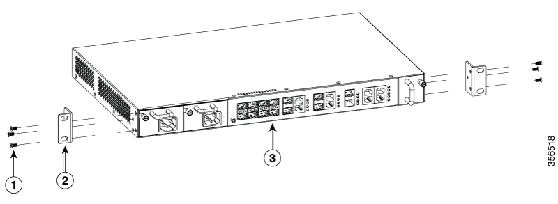
Use the Phillips head screwdriver and attach the 19-inch rack-mounting bracket to an OLT using the mounting-bracket screws. Follow the same steps to attach the second bracket to the other side.

Figure 1. Attaching Rack-Mounting Brackets on a CGP-OLT-8T

1

6xMounting-bracket screw

3

Front-mounting position

2

2xRack-mounting bracket

Figure 2. Attaching the Rack-Mounting Brackets on a CGP-OLT-16T

1

6xMounting-bracket screws

3

Front-mounting position

2

2xRack-mounting brackets

Step 2

Insert the OLT into the rack and align the brackets in the rack. Use the rack-mounting screws to secure the OLT to the rack.

Warning 

To prevent airflow restriction, allow clearance around the ventilation openings to be at least: 3 in. (7.6 cm) Statement 1076


Installing SFP or SFP+ Modules

Each Cisco module has an internal serial electrically erasable programmable read-only memory (EEPROM) that is encoded with security information. This encoding provides a way for Cisco to identify and validate that the module meets the requirements for the switch.

For information about installing, removing, cabling, and troubleshooting SFP modules, see the module documentation that is shipped along with your device.

Installing an SFP or SFP+ Module

Before you begin

When installing SFP or SFP+ modules, observe these guidelines:

  • Do not remove the dust plugs from the modules or the rubber caps from the fiber-optic cable until you are ready to connect the cable. The plugs and caps protect the module ports and cables from contamination and ambient light.

  • To prevent ESD damage, follow your normal board and component handling procedures when connecting cables to the devices.


    Caution

    Removing and installing an SFP or SFP+ module can shorten its useful life. Do not remove and insert any module more often than is necessary.


Procedure

Step 1

Attach an ESD-preventive wrist strap to your wrist and the other end to a bare metal surface.

Step 2

Find the send (TX) and receive (RX) markings on the module top.

Note 

On some SFP or SFP+ modules, the send and receive (TX and RX) markings might be replaced by arrows that show the direction of the connection.

Step 3

If the module has a bale-clasp latch, move it to the open, unlocked position.

Step 4

Align the module in front of the slot opening, and push until you feel the connector snapping into place.

Step 5

Close the module's bale-clasp latch.

Step 6

Connect the SFP cables to the modules.

Step 7

Store the dust plugs in a safe location.


Removing an SFP or SFP+ Module

Procedure

Step 1

Attach an ESD-preventive wrist strap to your wrist and the other end to a bare metal surface.

Step 2

Disconnect the cable from the SFP or SFP+ module. For purposes of reattachment, note which cable connector plug is send (TX) and which is receive (RX).

Step 3

Insert the dust plugs into the optical ports of the SFP or SFP+ module to keep the optical interfaces clean.

Step 4

If the module has a bale-clasp latch, pull the bale out and down to eject it from the module. If the latch is obstructed and you cannot use your finger, use a small flat-blade screwdriver or any other long and narrow instrument to open the latch.

Step 5

Grasp the SFP or SFP+ module, and carefully remove it from the module slot.

Step 6

Place the module in an antistatic bag or any other protective environment.


Establishing the System Ground

This section describes how to connect a system ground to the OLT.


Caution

Installations that rely solely on system grounding using only an AC third-prong ground, run a substantially greater risk of equipment problems and data corruption than those installations that use both the AC third-prong ground and a properly installed system ground.

The system ground provides additional grounding for EMI shielding requirements and grounding for the low voltage supplies (DC-DC converters) on the modules. You must observe the following system grounding guidelines for your chassis:

  • You must install the system ground connection with any other rack or system power ground connections that you make. The system ground connection is required if FXS modules are installed or if this equipment is installed in a U.S. or European Central Office.

  • You must connect both the system ground connection and the power supply ground connection to an earth ground. The system ground connection is required if FXS modules are installed or if this equipment is installed in a U.S. or European Central Office.

  • When using DC-input power supplies, you must install the system (ground before you attach the source DC power cables to the DC PEM. Power down the chassis before attaching the system ground.


Note

In all situations, grounding practices must comply with Section 250 of the National Electric Code (NEC) requirements or local laws and regulations. We recommend a 6-AWG grounding wire from the chassis to the rack ground or directly to the common bonding network (CBN). The equipment rack should also be connected to the CBN with a 6-AWG grounding wire.

The system ground serves as the primary safety ground for chassis that is equipped with DC-input power supplies. The DC-input power supplies for these chassis do not have a separate ground.


Required Tools and Equipment

To connect the system ground, you need the following tools and materials:

  • Grounding lug: When using the double-hole lug connector provided with the system, the ground wire must be 6-AWG only. Otherwise, a supported closed-loop ring connector must be used for 8-AWG to 14-AWG wire.

  • Grounding screws: One M4 x 8 mm (metric) pan-head screws. Supplied as part of the accessory kit.

  • Grounding wire: Not supplied as part of the accessory kit. The grounding wire should be sized according to local and national installation requirements. For U.S. installations, AC power supply systems require a 14-AWG copper conductor. We recommend a commercially available 8-AWG to 14-AWG wire. The length of the grounding wire depends on the proximity of the switch to proper grounding facilities.

  • No. 1 Phillips screwdriver.

  • Crimping tool to crimp the grounding wire to the grounding lug.

  • Wire-stripping tool to remove the insulation from the grounding wire.

Connecting the System Ground

To establish an earth ground for the chassis, you must attach a grounding cable from the OLT grounding lug to the rack.

Procedure

Step 1

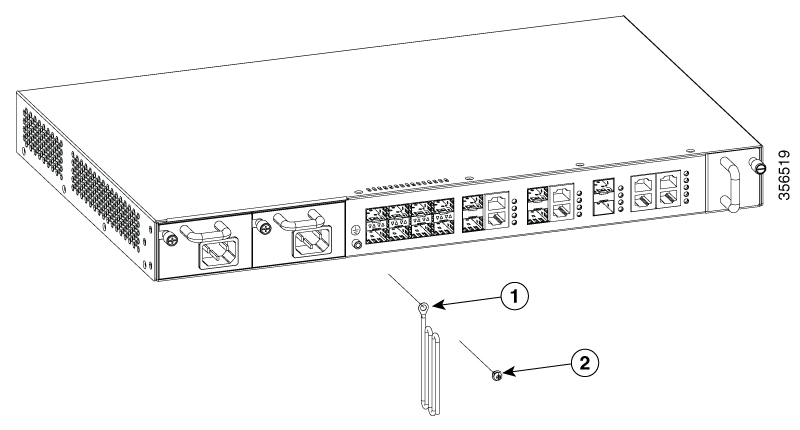
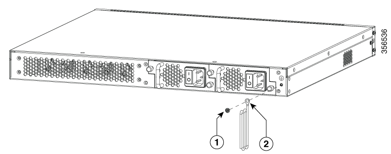
Secure the grounding lug to the OLT with an M4 screw. Ensure that the grounding lug and the grounding wire do not interfere with other hardware or rack equipment.

Figure 3. Connecting the System Ground for CGP-OLT-8T

1

Grounding wire with grounding lug

2

1xM4 screw

Figure 4. Connecting the System Ground for CGP-OLT-16T

1

1xM4 screw

2

Grounding wire with grounding lug

Step 2

Prepare the other end of the grounding wire with a ring lug, and secure it to the rack with a screw.


Connecting to the Power Source

Each power cable is shipped with mating connectors, with one of the connectors on the power socket and the other connector on the front panel of the power supply. The steps to install the AC-input and DC-input power supplies is the same, but you must ground them as explained below:

  • AC-input power supply: The device is automatically grounded when you connect its power cable to the power supply and the power source.

  • DC-input power supply: You must not connect the power supply directly to the earth ground.

Use one power cord for each power supply to connect the power supply to its power source.

Connecting to an AC Power Source


Warning

Take care when connecting units to the supply circuit so that wiring is not overloaded. Statement 1018
Before you begin

Prior to connecting the power supply to a power source, ensure that the chassis is properly grounded.

Procedure

Step 1

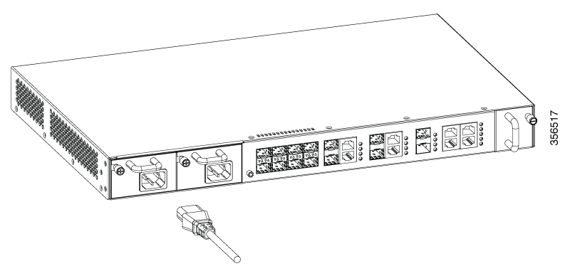
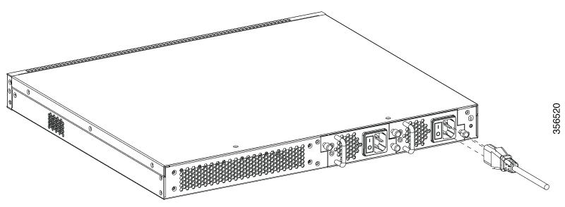
Plug the power cable into the power connector on the power supply unit of the OLT.

Figure 5. Connecting an AC Power Cable to CGP-OLT-8T
Figure 6. Connecting an AC Power Cable to CGP-OLT-16T
Step 2

Plug the other end of the power cable into a power source.

Step 3

Verify that the power supply is receiving power by checking whether the PWR1 or PWR2 LED is green.

Note 

If the LED does not turn on, check the power connections on the power supply and the power source.

Step 4

The OLT will automatically boot. The RUN LED keeps blinking green after the boot is completed.


Connecting to a DC Power Source

To connect the DC power supply directly to one or two DC power sources, follow these steps:


Warning

Before performing any of the following procedures, ensure that power is removed from the DC circuit. Statement 1003

Warning

Hazardous voltage or energy may be present on DC power terminals. Always replace cover when terminals are not in service. Be sure that the uninsulated conductors are not accessible when cover is in place. Statement 1075
Before you begin

Prior to connecting the power supply to a power source, ensure that the chassis is properly grounded.

Procedure

Step 1

Plug the DC power cable into the DC power supply.

Step 2

Turn off the power at the circuit breakers for the portions of the DC grid power that you are connecting to, and verify that all the LEDs on the DC grid power supplies are off.

Step 3

Loosen and unscrew the two nuts on the terminal box, which has two slots for power terminals. Each terminal has a nut that you can use to fasten the power cable to the terminal.

Step 4

Secure the positive (+) DC power cable lug to the RTN terminal, and the negative (–) DC power cable lug to the NEG terminal with the nuts.

Step 5

To tighten the nuts, apply torque between 7 lbf.in (0.8Nm) and 10lbf.in (1.1 Nm) to each nut.

Step 6

Verify that the power supply is receiving power by checking that the PWR1 LED is green.

Note 

If the LED does not turn on, check the power connections on the power supply and the power source.

The OLT starts automatically. The RUN LED keeps flashing green after the boot is completed.


Setting Up the OLT

Procedure


Step 1

Connect the RJ-45 connector end of the cable to the OLT console port.

Step 2

Connect the DB-9 adapter end to the serial port of a connected device, such as a PC.

Step 3

Reconfigure and reboot the connected device, if required.

Step 4

On the connected device, run the terminal emulation program such as Windows HyperTerminal.

Step 5

Set the following connection parameters and click OK:

  • Connection mode: Serial

  • Baud rate: 9600

  • Data bits: 8

  • Parity: None

  • Stop bits: 1

  • Flow controls: None

Step 6

On the console of the connected device, enter the following default credentials and press Enter:

  • username: admin

  • password: 123456


Installing an ONT

The following sections provide information about the various tasks that comprise the process of installing an ONT.

Placing the ONT on a Table or Shelf

Procedure


Step 1

Locate the adhesive strip with the rubber feet in the mounting-kit envelope.

Step 2

Attach the four rubber feet to the four circular etches on the bottom of the ONT.

Step 3

Place the ONT on a table or shelf near an AC power source.


Installing the ONT on a Wall


Warning

Read the wall-mounting instructions carefully before beginning installation. Failure to use the correct hardware or to follow the correct procedures could result in a hazardous situation to people and damage to the system. Statement 378


Caution

Do not wall-mount the switch with its front panel facing up. Following safety regulations, wall-mount the ONT with its front panel facing down or to the side to prevent airflow restriction and to provide easier access to the cables


Procedure


Step 1

Determine where you want to mount the ONT. Verify that the surface is smooth, flat, dry, and sturdy.

Step 2

Drill two pilot holes into the surface of the wall 153.20 mm apart.

Step 3

Insert a screw into each hole, leaving a gap between the surface and the base of the screw head.

Step 4

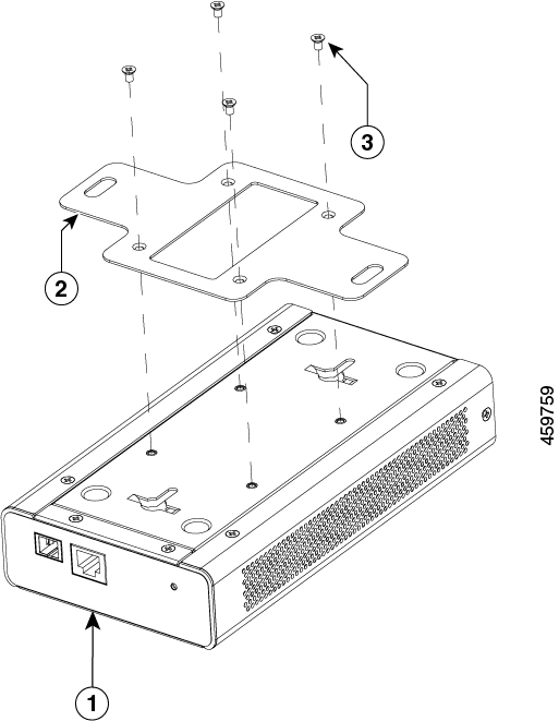
To attach a mounting bracket to the CGP-ONT-1P, perform the following steps:

  1. Place the mounting bracket with the side containing the text This side is close to the chassis to the base of the ONT.

  2. Use the Phillips head screwdriver and attach the mounting bracket to the ONT using the mounting bracket screws.

    Figure 7. Attaching the Mounting Bracket to the ONT

    1

    CGP-ONT-1P

    3

    4xMounting-bracket screw

    2

    Mounting bracket

    -

    -

Step 5

Place the bottom of the ONT over the screws on the wall and slide the ONT down until the screws fit snugly into the slots.


Attaching the Rack-Mounting Bracket and Mounting an ONT on a Rack


Warning

To prevent bodily injury when mounting or servicing this unit in a rack, you must take special precautions to ensure that the system remains stable. The following guidelines are provided to ensure your safety:

  • This unit should be mounted at the bottom of the rack if it is the only unit in the rack.

  • When mounting this unit in a partially filled rack, load the rack from the bottom to the top with the heaviest component at the bottom of the rack.

  • If the rack is provided with stabilizing devices, install the stabilizers before mounting or servicing the unit in the rack.

Statement 1006

Before you begin

Make sure that you have the mounting brackets that are included with the shipping box.

Procedure


Step 1

Use the Phillips head screwdriver and attach a rack-mounting bracket to an ONT using the mounting bracket screws. Follow the same steps to attach the second bracket to the other side.

Figure 8. Attaching Rack-Mounting Brackets to a CGP-ONT-4PVC

1

8xMouting-bracket screw

3

Front-mounting position

2

2xRack-mounting bracket

Step 2

Insert the ONT into the rack and align the bracket in the rack. Use the rack-mounting screws to secure the ONT in the rack.

Warning 

To prevent airflow restriction, allow clearance around the ventilation openings to be at least: 3 in. (7.6 cm). Statement 1076


Connecting to an AC Power Source


Warning

Take care when connecting units to the supply circuit so that wiring is not overloaded. Statement 1018

Before you begin

Prior to connecting the power supply to a power source, ensure that the ONT is properly grounded.

Procedure


Step 1

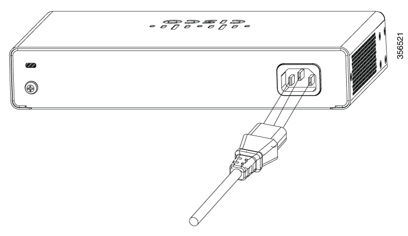
Plug the power cable into the power connector on the ONT.

Figure 9. Connecting an AC Power Cable to the CGP-ONT-4PVC
Step 2

Plug the other end of the power cable into a power source.

Step 3

Verify that the power supply is receiving power by checking whether the PWR LED is green.

Note 

If the LED does not turn on, check the power connections on the power supply and the power source.


Setting Up an ONT

Procedure


Step 1

Connect a straight-through Category 5 or Category 6 Ethernet cable to a 10/100/1000 Ethernet port on the PON port of the ONT and to the Ethernet port on the PC.

Step 2

Verify that the PC is on the same subnet as the ONT.

The default ONT IP address is 192.168.1.1. Ping the ONT from the console of the PC:

C:\Users\Cisco>ping 192.168.1.1
Pinging 192.168.1.1 with 32 bytes of data:
Reply from 192.168.1.1: bytes=32 time=2ms TTL=64
Reply from 192.168.1.1: bytes=32 time=3ms TTL=64
Ping statistics for 192.168.1.1:
    Packets: Sent = 4, Received = 4, Lost = 0 (0% loss),
Approximate round trip times in milli-seconds:
    Minimum = 2ms, Maximum = 3ms, Average = 2ms
Step 3

To log in to the device using an internet browser on your PC, enter the IP address 192.168.1.1 in the address bar of your internet browser and press Enter.

Step 4

Enter the following default credentials, and press Enter:

  • username: cisco

  • password: cisco


Installing Cisco Catalyst PON Manager

Before you begin

To avoid software conflicts during the installation of Cisco Catalyst PON Manager, turn off all the antivirus applications on your device.

Procedure


Step 1

Obtain the network management software installation package from Cisco.

Step 2

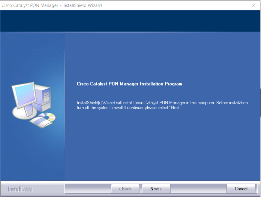
Double-click the installation package to enter the installation interface.

The installation wizard window is displayed.

Step 3

Click Next to begin the installation.

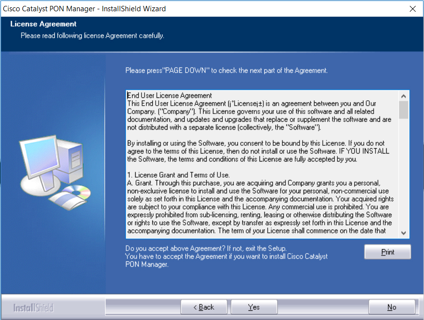
The License Agreement page is displayed.

Step 4

Click Yes to accept the end user license agreement and continue with the installation. Click Print to print the agreement.

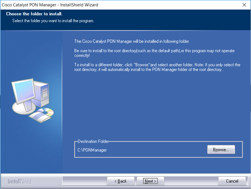
The Choose the folder to install page is displayed.

Step 5

Click Browse to change the folder location. Click Next to continue with the installation.

The Select Features page is displayed.

Step 6

Click Next to start the installation.

If the installation is successful, the installation complete page is displayed.

Step 7

Click Finish to complete the installation.

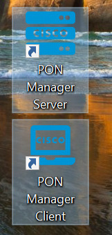
The server and client shortcut icons are created on the desktop.


Setting Up Cisco Catalyst PON Manager

To set up Cisco Catalyst PON Manager, you need to start the PON Manager Server and then create a new user name and password in the PON Manager Client.

Starting PON Manager Server

Procedure

Step 1

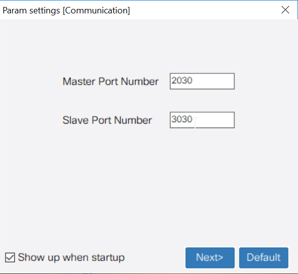
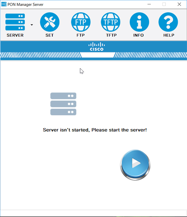
Double-click on the PON Manager Server icon, if installed on the desktop or click the Windows Start button and navigate to Cisco Catalyst PON Manager > PON Manager Server.

The PON Manager Server settings window is displayed.

Step 2

Continue clicking Next till the PON Manager Server home page is displayed.

Step 3

Click the start button to start the PON Manager server.


Creating a New User in PON Manager Client

Procedure

Step 1

Double-click on the PON Manager Client icon, if installed on the desktop or click the Windows Start button and navigate to Cisco Catalyst PON Manager > PON Manager Client.

The login page is displayed.

Step 2

In the Password field, enter the default password as cisco.

Step 3

Click Login.

A pop-up message is displayed asking you to change the user name and password.

Step 4

Click OK to continue.

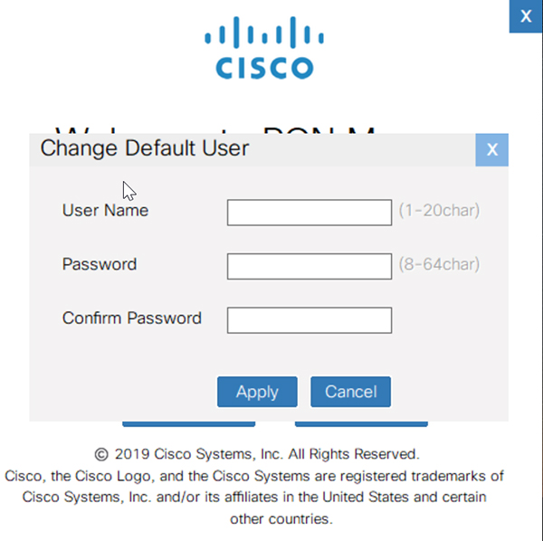
The Change Default User dialog box is displayed.

Step 5

In the User Name field, enter the new user name.

The allowed character range is from 1 to 20.

Step 6

In the Password field, enter the new password.

The allowed character range is from 8 to 64.

Step 7

In the Confirm Password field, reenter the new password.

Step 8

To save the changes, click Apply.

A confirmation message is displayed.

Step 9

Click OK.

The login page is displayed.