Configuring PTP

This chapter describes how to configure the Precision Time Protocol (PTP) on Cisco NX-OS devices.

This chapter includes the following sections:

About PTP

PTP is a time synchronization protocol defined in IEEE 1588 for nodes distributed across a network. With PTP, it is possible to synchronize distributed clocks with an accuracy of less than 1 microsecond via Ethernet networks. In addition, PTP's hardware timestamping feature provides timestamp information in the ERSPAN Type III header that can be used to calculate packet latency among edge, aggregate, and core switches.

A PTP system can consist of a combination of PTP and non-PTP devices. PTP devices include ordinary clocks, boundary clocks, and transparent clocks. Non-PTP devices include ordinary network switches, routers, and other infrastructure devices.

PTP is a distributed protocol that specifies how real-time PTP clocks in the system synchronize with each other. These clocks are organized into a master-slave synchronization hierarchy with the grandmaster clock, which is the clock at the top of the hierarchy, determining the reference time for the entire system. Synchronization is achieved by exchanging PTP timing messages, with the members using the timing information to adjust their clocks to the time of their master in the hierarchy. PTP operates within a logical scope called a PTP domain.

PTP supports the following functionality:

  • Multicast and unicast PTP transport—In the multicast transport mode, PTP uses multicast destination IP address 224.0.1.129 as per IEEE 1588 standards for communication between devices. For the source IP address, it uses the user configurable global IP address under the PTP domain. In the unicast transport mode, PTP uses configurable unicast source and destination IP addresses that can be configured under an interface. In both, the unicast and the multicast modes, PTP uses UDP ports, 319 for event messages and 320 for general messages communication between devices.

  • PTP multicast configuration is supported only under physical interface for L2 or L3. Unicast PTP configuration supported only under L3 physical interface. PTP is not supported for virtual interfaces such as Port-channel, SVI, and tunnel.

  • PTP encapsulation over UDP over IP—PTP uses UDP as the transport protocol over IP. In both, the unicast and multicast modes, PTP uses UDP ports 319 for event messages and 320 for general messages communication between devices. L2 encapsulation mode is not supported.

  • PTP profiles—PTP supports default (1588) , AES67, and SMPTE 2059-2 profiles. They all have different ranges of sync and delay request intervals. For information on the default profile, refer to IEEE 1588. For more information on AES67 and SMPTE 2059-2, refer to the respective specifications.

  • Path delay measurement—We support delay request and response mechanism to measure the delay between the master and slave devices. Peer delay request and response mechanism is not supported.

  • Message intervals—You can configure the interval at which the announce, sync, and delay request messages needs to be sent between devices.

  • Best master clock (BMC) selection—BMC algorithm is used to select master, slave, and passive states of the PTP enabled interfaces based on the Announce message received as per 1588 specification.

PTP Offload

This feature distributes the PTP functionality to the line cards and allows scaling of the number of PTP sessions that are supported on the system. This feature is available for Cisco Nexus 9500 platform switches with 9700-EX, 9700-FX, 9636C-R, 9636Q-R, 9624D-R2, and 9636C-RX line cards.

Dynamic Unicast

This feature allows BMCA to select roles dynamically as follows, rather than assigning static roles.

  • Use the ptp peer <ipv4>/<ipv6> command to configure Peer IPs.

  • Port remains in a Listening state until the Peer IP is reachable, when it transitions to Master state.

  • Announce packets are sent as soon as the peer is reachable.

  • Based on Announce packet (using BMCA), Role will be decided. Port state transitions accordingly.

PTP Time Distribution Hold

In a properly synchronized PTP network, when any PTP node goes down and comes up, the PTP clock is synchronized to its primary time source (GM). During this process, the local node has significant correction and it tries to correct its local clock. At that time, the node can send incorrect time to the downstream nodes and cause issues for all downstream nodes. The Time Distribution (TD) hold feature, introduced in Cisco NX-OS Release 10.5(1)F, resolves this issue by ensuring that the node is properly synchronized to its primary source and distributes time to the downstream nodes during boot up.

The TD hold feature holds the time distribution until a Boundary Clock (BC) node locks to the primary time source and settles down to the target correction value. The TD hold enabled node receives all PTP packets, does the normal state change, and synchronizes time, but it does not send any PTP packets out.


Note


If all nodes reboot at the same time (with a difference of few seconds), each node will be in active hold time, which sometimes results in no nodes having secondary port. This leads to the BMC taking a long time to find the best clock. Hence, the user needs to take this into account when enabling this feature.


PTP Device Types

The PTP device type is configurable and can be used to set the clock type.

Clocks

The following clocks are common PTP devices:

Ordinary clock

Communicates with the network based on a single physical port, similar to an end host. An ordinary clock can function as a grandmaster clock.

Boundary clock

Typically has several physical ports, with each port behaving like a port of an ordinary clock. However, each port shares the local clock, and the clock data sets are common to all ports. Each port decides its individual state, either master (synchronizing other ports connected to it) or slave (synchronizing to a downstream port), based on the best clock available to it through all of the other ports on the boundary clock. Messages related to synchronization and establishing the master-slave hierarchy terminate in the protocol engine of a boundary clock and are not forwarded.

Transparent clock

Forwards all PTP messages like an ordinary switch or router but measures the residence time of a packet in the switch (the time that the packet takes to traverse the transparent clock) and in some cases the link delay of the ingress port for the packet. The ports have no state because the transparent clock does not need to synchronize to the grandmaster clock.

There are two kinds of transparent clocks:

End-to-end transparent clock

Measures the residence time of a PTP message and accumulates the times in the correction field of the PTP message or an associated follow-up message.

Peer-to-peer transparent clock

Measures the residence time of a PTP message and computes the link delay between each port and a similarly equipped port on another node that shares the link. For a packet, this incoming link delay is added to the residence time in the correction field of the PTP message or an associated follow-up message.


Note


PTP operates only in boundary clock mode. Cisco recommends deployment of a Grand Master Clock (10 MHz) upstream, with servers containing clocks requiring synchronization connected to the switch.

End-to-end transparent clock and peer-to-peer transparent clock modes are not supported.


Grandmaster clock

In a single PTP domain, the Grandmaster (GM) node acts as a primary clock source for the entire PTP network. The primary source for GM node will be taken either from internal GNSS system or external GNSS system. GM node can’t synchronize time or frequency from other PTP node i.e. GM node can’t have any slave ports, all ports act as only Master role.

Clock Modes

The IEEE 1588 standard specifies two clock modes for the PTP supporting devices to operate in: one-step and two-step.

One-Step Mode:

In one-step mode the clock synchronization messages include the time at which the master port sends the message. The ASIC adds the timestamp to the synchronization message as it leaves the port. The master port operating in one-step mode is available for Cisco Nexus 9508-FM-R and 9504-FM-R fabric modules and Cisco Nexus 9636C-R, 9636Q-R, 9624D-R2, and 9636C-RX line cards.

The slave port uses the timestamp that comes as part of the synchronization messages.

Two-Step Mode:

In two-step mode the time at which the synchronization message leaves the port is sent in a subsequent follow-up message. This is the default mode.

PTP Process

The PTP process consists of two phases: establishing the master-slave hierarchy and synchronizing the clocks.

Within a PTP domain, each port of an ordinary or boundary clock follows this process to determine its state:

  • Examines the contents of all received announce messages (issued by ports in the master state)

  • Compares the data sets of the foreign master (in the announce message) and the local clock for priority, clock class, accuracy, and so on

  • Determines its own state as either master or slave

The ordinary and boundary clocks use Sync , Delay_Req , Follow_Up , Delay_Resp event messages to generate and communicate timing information.

These messages are sent in the following sequence:

  1. The master sends a Sync message to the slave and notes the time, t1 at which it was sent. For one-step Sync message carries the time when the message leaves the master and for two-step this time is sent in the subsequent Follow-Up event message.

  2. The slave receives the Sync message and notes the time of reception, t2.

  3. The master conveys to the slave the timestamp, t1 by embedding the timestamp in a Follow_Up event message.

  4. The slave sends a Delay_Req message to the master and notes the time, t3 at which it was sent.

  5. The master receives the Delay_Req message and notes the time of reception, t4.

  6. The master conveys to the slave the timestamp, t4 by embedding it in a Delay_Resp message.

  7. After this sequence, the slave possesses all four timestamps. These timestamps can be used to compute the offset of the slave clock relative to the master, and the mean propagation time of messages between the two clocks.

    The following figure describes the event messages in the PTP process that generate and communicate timing information.

    Figure 1. PTP Process
    Event messages that generate and communicate timing information

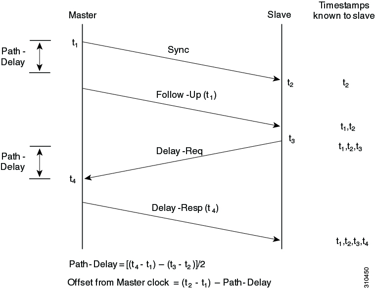
ITU-T Telecom Profile for PTP

Cisco NX-OS software supports ITU-T Telecom Profiles for PTP as defined in the ITU-T recommendation. A profile consists of PTP configuration options applicable only to a specific application.

Separate profiles can be defined to incorporate PTP in different scenarios based on the IEEE 1588-2008 standard. A telecom profile differs in several ways from the default behavior defined in the IEEE 1588-2008 standard and the key differences are mentioned in the subsequent sections.

The following sections describe the ITU-T Telecom Profiles that are supported for PTP:

Telecom Profile G.8275.1

Cisco's Telecom Profile G.8275.1 feature supports the ITU-T G.8275.1 : Precision time protocol telecom profile for phase/time synchronization with full timing support from the network standard. The G.8275.1 profile fulfills the time-of-day and phase synchronization requirements in telecom networks with all network devices participating in the PTP protocol. The G.8275.1 profile with SyncE provides better frequency stability for the time-of-day and phase synchronization.

Features of the G.8275.1 profile are:

  • Synchronization Model: G.8275.1 profile adopts hop-by-hop synchronization model. Each network device in the path from master to slave synchronizes its local clock to upstream devices and provides synchronization to downstream devices.

  • Clock Selection: G.8275.1 profile also defines an alternate BMCA that selects a clock for synchronization and port states for the local ports of all devices in the network. The parameters defined as a part of the BMCA are:

    • Clock Class

    • Clock Accuracy

    • Offset Scaled Log Variance

    • Priority 2

    • Local Priority

    • Clock Identity

    • Steps Removed

    • Port Identity

  • Port State Decision: The port states are selected based on the alternate BMCA.

  • Alternate BMCA: It follows the alternate BMCA dataset comparison algorithm as defined in Rec. ITU-T G.8275.1/Y.1369.1 to select the GM for the node.

  • Packet Rates: The nominal packet rate for Announce packets is 8 packets-per-second and 16 packets-per-second for Sync/Follow-Up and Delay-Request/Delay-Response packets.

  • Transport Mechanism: G.8275.1 profile only supports Ethernet PTP transport mechanism.

  • Mode: G.8275.1 profile supports transport of data packets only in multicast mode. The forwarding is done based on forwardable or non-forwardable multicast MAC address.

  • Clock Type: G.8275.1 profile supports the following clock types:

    • Telecom Grandmaster (T-GM): Provides timing for other network devices and does not synchronize its local clock to other network devices.

    • Telecom Time Slave Clock (T-TSC): A slave clock synchronizes its local clock to another PTP clock, but does not provide PTP synchronization to any other network devices.

    • Telecom Boundary Clock (T-BC): Synchronizes its local clock to a T-GM or an upstream T-BC clock and provides timing information to downstream T-BC or T-TSC clocks.


    Note


    Telecom Boundary Clock (T-BC) is the only clock type supported in Cisco NX-OS Release 9.3(5).


  • Domain Numbers: The domain numbers that can be used in a G.8275.1 profile network ranges from 24 to 43. The default domain number is 24.

Telecom Profile G.8275.2

Cisco's Telecom Profile G.8275.2 feature supports the ITU-T G.8275.2 : Precision time protocol telecom profile for phase/time synchronization with partial timing support from the network standard. The G.8275.2 is a PTP profile for use in telecom networks where phase or time-of-day synchronization is required. It differs from G.8275.1 in that it is not required that each device in the network participates in the PTP protocol. Also, G.8275.2 uses PTP over IPv4 and IPv6 in unicast mode.

The G.8275.2 profile is based on the partial timing support from the network. Hence, nodes using G.8275.2 are not required to be directly connected. The G.8275.2 profile is used in mobile cellular systems that require accurate synchronization of time and phase. For example, the fourth generation (4G) of mobile telecommunications technology.

With upcoming technologies such as LTE-TDD, LTE-A CoMP, LTE MBSFN and Location-based services, eNodeBs (base station devices) are required to be accurately synchronized in phase and time. Having GNSS systems at each node is not only expensive, but also introduces vulnerabilities. The G.8275.2 profile meets the synchronization requirements of these new technologies.

PTP Ports

A port can be configured to change its role dynamically. If no role is assigned to a port, it can dynamically assume a primary, passive, or subordinate role based on the BMCA.

In G.8275.2, PTP ports are not tied to any specific physical interfaces, but are tied to a loopback (virtual) interface. Traffic from a PTP port is routed through any physical interface based on the routing decision. For a dynamic port, only one clock source can be configured.

Alternate BPCA

The BPCA (Best Primary Clock Algorithm, which is also known as Best Master Clock Algorithm (BMCA [RFCÂ 7273]) implementation in G.8275.2 is different from that in the default PTP profile. The G.8275.2 implementation specifies an alternate best primary clock algorithm (ABPCA), which is used by each device to select a clock to synchronize to, and to decide the port states of its local ports.

The following consideration apply to the G.8275.2 implementation of the BPCA:

  • PrimaryOnly—A per port attribute, PrimaryOnly defines the state of the port. If this attribute is true, the port is never placed in the subordinate state.

  • Priority 1—Priority 1 is always static in this profile and is set to 128. Priority 1 is not used in BPCA.

  • Priority 2—Priority 2 is a configurable value and its range if from 0 to 255.

  • Local Priority—Local priority is configured locally on clock ports to set the priority on nominated clocks. The default value is 128 and valid range is from 1 to 255.

Restrictions for Using the G.8275.2 Profile
  • In the G.8275.2 profile, PTP is supported only in the none mode (default).

  • A G.8275.2 PTP clock can have redundant clock sources configured (through multiple PTP ports). However, at any given time, a G.8275.2 PTP clock synchronizes to only one clock source, which is selected by BMCA.

  • The G.8275.2 does not provide any recommendations for performance analysis and network limits for the clocks.

Guidelines and Limitations for PTP


Note


For scale information, see the release-specific Cisco Nexus 9000 Series NX-OS Verified Scalability Guide.


The following are the guidelines and limitations for Cisco Nexus 9000 Series switches for PTP:

  • For PTP to function properly, you must use the latest SUP and line card FPGA versions. For information on upgrading FPGAs, access the Release Notes landing page and go to the FPGA/EPLD Upgrade Release Notes (NX-OS Mode Switches) section and locate the FPGA/EPLD Upgrade Release Notes for your software version. Refer to the Installation Guidelines topic.

  • Beginning with Cisco NX-OS Release 9.3(3), PTP is supported on Cisco Nexus 93360YC-FX2 and 93216TC-FX2 switches.

  • Beginning with Cisco NX-OS Release 9.3(5), PTP G.8275.1 Telecom profile is supported on N9K-C93180YC-FX3S platform switch.

  • Beginning with Cisco NX-OS Release 9.3(5), PTP is supported on N9K-C93108TC-FX3P platform switch. However, syncE is not supported.

  • Beginning with Cisco NX-OS Release 9.3(7), PTP G.8275.1 Telecom profile is supported on N9K-C93180YC-FX3 platform switch.

  • Starting from Cisco NX-OS Release 10.2(1)F, explicit carving of ing-sup (size of the ingress supervisor TCAM region) to 768 is not required for the PTP profile 8275-1.

  • PTPv1 forwarding and feature VMCT are not supported if enabled at the same time.

  • PTP Telecom Profile has the following guidelines and limitations:

    • PTP Telecom Profile is supported only on the Cisco Nexus 93180YC-FX3S switch and N9K-C93180YC-FX3 switch.

    • 1 Pulse per Second (1PPS) output is enabled by default. UTC/SMB port is in output mode. Note that 1PPS output is not supported.

    • Only PTP class B is supported for 25G and above port speed.

    • Only Telecom Boundary Clock (T-BC) is supported.

    • Cisco's Telecom Profile G.8273.2 feature is compliant with the ITU-T G.8273.2 : Timing characteristics of telecom boundary clocks and telecom time slave clocks standard with the exception that 1PPS output is not aligned with PTP.


      Note


      Time of Day and PTP GM are not supported in Cisco NX-OS Release 9.3(5).


    • Beginning with Cisco NX-OS Release 10.4(3)F, PTP Telecom Profile over MACsec is supported on Cisco Nexus 9300-H2R/H1 platform switches.

  • Beginning with Cisco NX-OS Release 9.3(5), PTP is supported on Cisco Nexus 9300-GX platform switches.

  • Beginning with Cisco NX-OS Release 9.3(5), CLI behavior for PTP commands has changed as follows:

    • Most PTP commands do not return errors if the same command is applied again.

    • Most PTP commands do not validate the parameters that are entered as "no" commands. For example, if the currently configured command is "ptp sync interval -3", "no ptp sync interval -1" is accepted for negation.

  • PTP domain limits to a single domain per network.

  • PTP transport over User Datagram Protocol (UDP) is supported. PTP over Ethernet is supported only on Cisco Nexus 9300-FX3 platform switches.

  • PTP supports the multicast communication. PTP also supports the unicast communication and the unicast mode is optional.

  • PTP supports boundary clock mode. End-to-end transparent clock and peer-to-peer transparent clock modes are not supported.

  • PTP can be enabled on the port-channel member ports.

  • All management messages that are received from a slave port are forwarded to all PTP enabled ports. The management messages that are received from a slave port are not handled.

  • PTP is not supported on Cisco Nexus 92348GC-X platform switch.

  • Timestamp Tagging (TTAG) is supported on the following platform switches:

    • Cisco Nexus 9200 platform switches: beginning with Cisco NX-OS Release 7.0(3)I6(1)

    • Cisco Nexus 9364C: beginning with Cisco NX-OS Release 7.0(3)I7(2)

    • Cisco Nexus 9332C: beginning with Cisco NX-OS Release 9.2(3)

    • Cisco Nexus 9300-EX platform switches: beginning with Cisco NX-OS Release 7.0(3)I6(1)

    • Cisco Nexus 9300-FX platform switches: beginning with Cisco NX-OS Release 7.0(3)I7(3)

    • Cisco Nexus 9300-FX2 platform switches: beginning with Cisco NX-OS Release 9.3(3)

    • Cisco Nexus 9300-FX3 and -GX platform switches: beginning with Cisco NX-OS Release 9.3(5)

    • Cisco Nexus 9500 platform switches with -EX and -FX line cards

  • To match PTP control packets using RACL, enable PIM on the L3 interface.

  • When configuring PTP to Cisco Nexus 9000 Series switches, set the clock protocol to use PTP through the clock protocol ptp vdc 1 command.

  • PTP is not available for all Cisco Nexus 9000 series and 3164Q hardware except for the 100G 9408PC line card and the 100G M4PC Generic Expansion Module (GEM).

  • Beginning with Cisco NX-OS Release 9.2(3), PTP is available for Cisco Nexus 9504-FM-R platform switches.

  • The PTP correction-range, PTP correction-range logging, and PTP mean-path-delay commands are supported on the Cisco Nexus 9508-R line cards.

  • For Cisco Nexus 31108PC-V and 31108TC-V switches, PTP is not supported on ports running at 100G speed.

  • Cisco Nexus 9000 series switches support mixed non-negotiated mode of operation on master PTP ports. That means when a slave client sends unicast delay request PTP packet, the Cisco Nexus 9000 responds with a unicast delay response packet. And, if the slave client sends multicast delay request PTP packet, the Cisco Nexus 9000 responds with a multicast delay response packet. For mixed non-negotiated mode to work, the source IP address used in the ptp source IP address configuration on the BC device must also be configured on any physical or logical interface of the BC device. The recommended best practice is to use the loopback interface of the device.

  • Beginning with Cisco NX-OS Release 9.2(1), Cisco Nexus 9732C-EX, 9736C-EX, and 97160YC-EX line cards support PTP offloading.

  • Before downgrading from Cisco NX-OS Release 9.3(1) to Release 7.0(3)I7, you must unconfigure PTP offload. PTP offloading is not supported for Cisco Nexus 9000 platform switches on 9636PQ, 9564PX, 9464PX, and 9536PQ line cards for Cisco NX-OS Release 7.0(3)I7.

  • Cisco Nexus 93108TC-EX and 93180YC-EX switches support PTP in mixed mode and unicast mode. The Cisco Nexus 9396 switch supports PTP mixed mode.

  • PTP is supported with sync interval -3 only on Cisco Nexus 9508-R family line cards. Higher sync intervals are not supported.

  • PTP unicast is supported only on the default vrf (PTP unicast is not supported in offload mode).

  • PTP is not supported for stateful high availability.

  • PTP is not supported for management interfaces.

  • PTP supports mixed mode for delivering PTP messages, which is detected automatically by a Cisco Nexus device based on the type of delay request message that is received from a connected client and no configuration is required.

  • One-step PTP is only supported on Cisco Nexus 9000-R series platform switches.

  • PTP is not supported on FEX interfaces.

  • PTP-capable ports do not identify PTP packets and do not time-stamp or redirect those packets unless you enable PTP on those ports.

  • The Cisco Nexus 9504 and 9508 platform switches with 9636C-R, 9636C-RX, or 9636Q-R line cards, the master ports can operate in one-step mode.

  • PTP one-step mode is supported only in PTP offload mode for the Cisco Nexus 9504 and 9508 platform switches with 9636C-R, 9636C-RX, 9624D-R2, or 9636Q-R line cards. Beginning with Cisco NX-OS Release 9.3(3), PTP offload is automatically enabled when one-step mode is configured.

  • In a topology where PTP is enabled, when a profile is set on a GrandMaster device, and the redundant GrandMasters are deployed in the network; to change the profile on the GrandMaster, you must first shut down the port that is configured on the GrandMaster to the switches, then change the profile, and then re-enable the port. For example, moving from an AES7 profile to an SMPTE profile or conversely.

  • Each port can be individually configured with any of the supported PTP profiles. Different PTP profiles can coexist on an interface. Combination of the default of 1588 and SMPTE-2059-2 or AES67 profiles is supported. However, combination of SMPTE-2059-2 and AES67 profiles is not supported on the same interface.

  • PTP is not supported on N9K-C92348GC-X.

  • Beginning with Cisco NX-OS Release 10.1(2), PTP (IEEE 1588) is supported on the N9K-C9700-GX line card, as well as N9K-C9700-EX and N9K-C9700-FX line cards, used with N9K-C9504-FM-G and N9K-C9508-FM-G fabric modules.

  • Beginning with Cisco NX-OS Release 10.1(2), PTP is supported on the N9K-X9624D-R2 line cards.

  • Beginning with Cisco NX-OS Release 10.2(1q)F, PTP is supported on the N9K-C9332D-GX2B platform switches. However, PTP is not supported on 1/33 and 1/34 ports.

  • Beginning with Cisco NX-OS Release 10.2(1)F, PTP IPv6 transport is supported on N9K-C93180YC-FX3S platform.

  • The QoS TCAM region Ingress SUP [ingress-sup] must be set to 768 or higher for PTP IPv6 transport to work.

  • Beginning with Cisco NX-OS Release 10.2(1)F, unicast-negotiation is supported for IPv4 and IPv6 addresses with default profile on N9K-C93180YC-FX3S platform..

  • The platform switches are supported only on Class B and do not meet Class C support.

  • There is no CLI profile command for 8275.2. This will be added only when the APTS is supported. The functions for this release work only in default mode.

  • Beginning with Cisco NX-OS Release 10.2(2)F, the PTP IPv6 UDP transport feature is supported on the Cisco Nexus 9300-FX, 9300-FX2, 9300-GX, and 9300-GX2 platform switches.

  • Beginning with Cisco NX-OS Release 10.2(2)F, the PTP unicast negotiation feature is also supported on Cisco Nexus 9300-EX, 9300-FX, 9300-FX2, 9300-GX, and 9300-GX2 platform switches.

  • Beginning with Cisco NX-OS Release 10.2(2)F, the PTP with jitter fix for 1G ports feature is supported on the Cisco N9K-C93108TC-FX3P platform switches.

  • Beginning with Cisco NX-OS Release 10.2(2)F, the PTPv1 and v2 co-existence feature is supported on the Cisco Nexus 9300-GX, 9300-GX2, and 9300-FX3 platform switches.

  • Beginning with Cisco NX-OS Release 10.2(3)F, PTP is not supported on specific ports for the following platforms:

    • N9K-C9364D-GX2A - PTP is not supported on 1/65 and 1/66 ports

    • N9K-C9348D-GX2A - PTP is not supported on 1/49 and 1/50 ports

  • Beginning with Cisco NX-OS Release 10.2(3)F, the PTP Support of up to 2000 Secondary Devices per Switch feature provides an option to support a maximum of 100 multicast secondary devices per port, with a system-wide support for a maximum of 2000 multicast secondary devices per switch. This feature is only supported on Cisco Nexus 9000-FX2 and 9000-FX3 platform switches.

  • Beginning with Cisco NX-OS Release 10.4(3)F, transmit and receive scope for PTP over IPv6 multicast configuration is supported.

  • Beginning with Cisco NX-OS Release 10.3(1)F, PTP Media Profile and One-Step Mode are supported on the Cisco Nexus 9808 platform switches. A few guidelines and limitations for this platform switches are as follows:

    • Only IPv4 transport is supported

    • Only multicast PTP with one step is supported

    • Other PTP features such as unicast and unicast negotiation are not supported

  • Beginning with Cisco NX-OS Release 10.3(2)F, PTP on media profile is supported on Cisco Nexus 9408 platform switches. A few guidelines and limitations for this platform switches are as follows:

    • Only multicast PTP with one-step is supported.

    • Other PTP features such as unicast and unicast negotiation are not supported.

  • Beginning with Cisco NX-OS Release 10.3(2)F, PTP GM functionality is supported on the Cisco Nexus N9K-C93180YC-FX3 platform switches.

  • Beginning with Cisco NX-OS Release 10.3(3)F, 8275.2 Telecom profile is supported on Cisco Nexus 9300-FX3 platform switches. The following guidelines and limitations apply:

    • This feature allows ITU-T precision time protocol (PTP) profile for phase/time distribution with partial timing support from the network (unicast mode).

    • A command for G.8275.2 is added as the APTS is supported.

    • This feature also supports multiple unicast followers. Among the unicast followers, one is picked as an active unicast follower, while the rest configured unicast followers act as passive.

    • From this release onwards, dynamic role with unicast ports is supported.

    • For dynamic PTP unicast ports, the unicast-negotiation feature must be enabled.

  • Beginning with Cisco NX-OS Release 10.4(1)F, Precision Time Protocol (PTP) is not supported on Cisco Nexus C9348GC-FX3PH switch.

  • Beginning with Cisco NX-OS Release 10.4(2)F, default PTP is supported on Cisco Nexus C93108TC-FX3 switch.

  • Beginning with Cisco NX-OS Release 10.4(1)F, Precision Time Protocol (PTP) is supported on Cisco Nexus C9348GC-FX3 switch.


    Note


    Make sure that you increase COPP limit to have PTP state stable across PTP interfaces. For more information on configuration, see CoPP Configuration Example section in Cisco Nexus 9000 Series NX-OS Security Configuration Guide.


  • Beginning with Cisco NX-OS Release 10.4(1)F, ASIC-based time stamping on 1G PTP enabled ports is supported on N9K-C931806C-FX3 and N9K-C93108TC-FX3P platform switches. Thus, both 1G and 10G ports can run on ASIC mode now. However, all the 1G ports must be either in PHY mode (default) or in ASIC mode. A global command is introduced to enable this feature.

  • Beginning with Cisco NX-OS Release 10.4(1)F, the PTP Class C support for G.8275.1 Telecom profile feature is supported on Cisco Nexus 9408 and N9K-C9332D-H2R platform switches. A few guidelines and limitations for this platform switches are as follows:

    • The platform switches provide Class C support

    • Only One-Step Mode is supported

    • Ethernet transport is supported

    • System can take up to 30 minutes to achieve Class C level corrections

    • The G.8275.1 Telecom profile is supported, except the following:

      • Telecom Transparent Clock (T-TC)

      • Telecom Grand Master (T-GM)

  • Beginning with Cisco NX-OS Release 10.4(1)F, PTP v1 packet forwarding feature is supported on Cisco Nexus N9K-C9408 and N9K-C9332D-H2R platform switches.

  • Beginning with Cisco NX-OS Release 10.4(1)F, PTP on media profile is supported on N9K-C9332D-H2R platform switch. A few guidelines and limitations for this platform switch are as follows:

    • Only multicast PTP with one-step is supported

    • Unicast is not supported

    • PTP is not supported on interface Ethernet 1/33 and Ethernet 1/34

  • Beginning with Cisco NX-OS Release 10.4(1)F, PTP is supported on the following switches and line cards:

    • Cisco Nexus 9804 switch and the following guidelines and limitations apply:

      • Only IPv4 transport is supported.

      • Only media profile is supported.

      • Only supported clock distribution mode is one step. Two step mode is not supported.

      • Other PTP features such as unicast and unicast negotiation are not supported.

    • Cisco Nexus X98900CD-A and X9836DM-A line cards with Cisco Nexus 9808 and 9804 switches

  • Beginning with Cisco NX-OS Release 10.4(2)F, PTP Class C is now supported on N9K-C93400LD-H1 switches. The guidelines and limitations for this platform switches are as follows:

    • Only One-Step Mode is supported.

    • System can take a maximum of 30 minutes to achieve Class C level corrections

    • Both G.8275.1 and G.8275.2 Telecom profiles are supported, However, only Telecom Boundary Clock (T-BC) mode is supported.

  • Beginning with Cisco NX-OS Release 10.4(2)F, 8275.2 PTP profile is supported on Cisco Nexus 9300-FX3, 9332D-H2R, 93400LD-H1, and 9408 platform switches. The guidelines and limitations are as follows:

    • Supports Unicast negotiation (simple unicast is not supported)

    • Default role for a dynamic unicast port is dynamic. The negotiation is triggered by state transitions. Only one PTP peer can be configured

    • Introduced a new command - ptp peer <ipv4>/<ipv6> - to configure a ptp peer when the role is dynamic.

    • For information about DME, see Cisco Nexus NX-API References.

  • Beginning with Cisco NX-OS Release 10.4(3)F, the following PTP profiles are supported on Cisco Nexus 9364C-H1 switch:

    • Default profile

    • Media profiles (AES67 and SMPTE 2059-2)

    • PTP telecom profile (only 8275-2)

  • Beginning with Cisco NX-OS Release 10.4(3)F, new global and interface commands are introduced to set the transmit and receive scope for PTP over IPv6 multicast configuration. If upgrading the devices to 10.4(3)F or higher, peer devices running NX-OS should also be upgraded to 10.4(3)F or higher for PTP over IPv6 multicast to work.


    Note


    If any devices are not upgraded, then configure the workaround CLI test system internal ptp ipv6-mcast-ipv4-dmac int-name in the devices which are upgraded to 10.4(3)F.


  • Beginning with Cisco NX-OS Release 10.5(1)F, the following attributes are added to the PTP high-correction notification:

    • lastHighCorrectionMPD

    • maxHighCorrectionTime

    • maxHighCorrectionValue

    • maxHighCorrectionMPD

  • Beginning with Cisco NX-OS Release 10.5(1)F, the PTP Time Distribution (TD) hold feature is introduced. This feature allows for holding the time distribution until a Boundary Clock node locks to the primary time source and settles down to the target correction value.

Default Settings for PTP

The following table lists the default settings for PTP parameters.

Table 1. Default PTP Parameters
Parameters Default

PTP

Disabled

PTP version

2

PTP domain

0

PTP priority 1 value when advertising the clock

255

PTP priority 2 value when advertising the clock

255

PTP announce interval

1 log second

PTP announce timeout

3 announce intervals

PTP delay-request interval

  • 0 log seconds

  • -1 log seconds for Cisco Nexus 3232C, 3264Q, and 9500 platform switches

PTP sync interval

  • -2 log seconds

  • -3 log seconds for Cisco Nexus 3232C, 3264Q, and 9500 platform switches

PTP VLAN

gPTP supports only default vlan 1, and no other user configured VLANs.

Configuring PTP

Configuring PTP Globally

You can enable or disable PTP globally on a device. You can also configure various PTP clock parameters to help determine which clock in the network has the highest priority to be selected as the grandmaster.


Note


For PTP to function properly, you must use the latest SUP and LC FPGA versions. For information on upgrading FPGAs, access the Release Notes landing page and go to the FPGA/EPLD Upgrade Release Notes (NX-OS Mode Switches) section and locate the FPGA/EPLD Upgrade Release Notes for your software version. Refer to the Installation Guidelines topic.


Note


You must always set the clock protocol PTP vdc1 for the local clock to be updated by the PTP protocol, irrespective of the one-step or the two-step mode. You can verify the configuration using the show running-config clock_manager command.

SUMMARY STEPS

  1. configure terminal
  2. [no] feature ptp
  3. (Optional) [no] ptp scale-on-1G
  4. [no] ptp device-type [generalized-ptp | boundary-clock | ordinary-clock-grandmaster]
  5. [no] ptp source {<ipv4 address> | <ipv6 address>} [ vrf <vrf-name>]
  6. (Optional) [no] ptp domain number
  7. (Optional) [no] ptp offload
  8. (Optional) [no] ptp clock-operation one-step
  9. (Optional) [no] ptp priority1 value
  10. (Optional) [no] ptp priority2 value
  11. [ no ] ptp management
  12. (Optional) [no] ptp delay tolerance { mean-path | reverse-path } variation
  13. (Optional) ptp forward-version1
  14. (Optional) ptp unicast-negotiation
  15. (Optional) ptp ipv6 multicast scope tx <scope>
  16. (Optional) ptp ipv6 multicast scope rx <scope>
  17. (Optional) [no] ptp time distribution-hold [correction-threshold <corr_limit>] [delay-threshold <max_delay_time>]
  18. (Optional) copy running-config startup-config

DETAILED STEPS

  Command or Action Purpose

Step 1

configure terminal

Example:

switch# configure terminal
switch(config)#

Enters global configuration mode.

Step 2

[no] feature ptp

Example:

switch(config)# feature ptp

Enables or disables PTP on the device.

Note


Enabling PTP on the switch does not enable PTP on each interface.

Make sure that only one of these features is configured: dot1x (feature dot1x ) or NV overlay (feature nv overlay ). A dynamic ifacl label is reserved when these features are configured. However, only two dynamic ifacl label bits are available. If both of these features are already configured, a dynamic ifacl label will not be available for PTP, and the feature cannot be enabled.

Step 3

(Optional) [no] ptp scale-on-1G

Example:

switch(config)# ptp scale-on-1G
(Optional)

Enables time stamping on ASIC for 1G ports (by default, PHY mode is enabled).

Step 4

[no] ptp device-type [generalized-ptp | boundary-clock | ordinary-clock-grandmaster]

Example:

switch(config)# ptp device-type generalized-ptp
Configures the device type as gPTP or boundary clock or ordinary clock grandmaster.

Note


The generalized-ptp option is available only for Cisco Nexus 9508 switches with an -R series line card.

Note


Beginning with Cisco NX-OS Release 10.3(2)F, the ordinary clock grandmaster is available only for Cisco Nexus N9K-C93180YC-FX3 platform switches. For more information, refer to Configuring PTP GM.

Step 5

[no] ptp source {<ipv4 address> | <ipv6 address>} [ vrf <vrf-name>]

Example:

switch(config)# ptp source 10.10.10.1

Configures the source IPv4/IPv6 address for all the PTP packets in the multicast PTP mode.

If the IP address is in non-default VRF, use the vrf parameter to configure the VRF.

Corresponding source address (IPv4/IPv6) is needed before enabling PTP IPv4/IPv6 transport on an interface.

Note


IPv6 source is supported on Cisco Nexus 93180TC-FX3S switch starting with 10.2(1)F release. Beginning with Cisco NX-OS Release 10.2(2)F, this option is also available on Cisco Nexus 9300-FX, 9300-FX2, 9300-GX, and 9300-GX2 platform switches.

Step 6

(Optional) [no] ptp domain number

Example:

switch(config)# ptp domain 1
(Optional)

Configures the domain number to use for this clock. PTP domains allow you to use multiple independent PTP clocking subdomains on a single network.

The range for the number is from 0 to 127.

Step 7

(Optional) [no] ptp offload

Example:

switch(config)# ptp offload
(Optional)

Increases the number of PTP sessions by offloading some timers to the line card.

This step is required for one-step mode and optional for two-step mode.

Note


Make sure that neither of these features are already configured: dot1x (feature dot1x ) and NV overlay (feature nv overlay ). A dynamic ifacl label is reserved when these features are configured. However, only two dynamic ifacl label bits are available. If either of these features are already configured, a dynamic ifacl label will not be available for PTP offload, and the feature cannot be enabled. Note that PTP (feature ptp ) consumes one ifacl label.

Note


Beginning with Cisco NX-OS Release 9.3(3), Cisco Nexus 9504 and 9508 platform switches with 9636C-R, 9636C-RX, or 9636Q-R line cards support offload only with one-step clock operation. PTP offload is automatically enabled or disabled when the one-step clock operation is enabled or disabled.

Step 8

(Optional) [no] ptp clock-operation one-step

Example:

switch(config)# ptp clock-operation one-step
(Optional)

Configures the PTP clock operation to the one-step mode. In this case, the timestamp message is sent as a part of the sync message. A followup message is not sent in this mode.

Step 9

(Optional) [no] ptp priority1 value

Example:

switch(config)# ptp priority1 1
(Optional)

Configures the priority1 value to use when advertising this clock. This value overrides the default criteria (clock quality, clock class, and so on) for best master clock selection. Lower values take precedence.

The range for the value is from 0 to 255.

Note


For the switch to synchronize with an external Grand Master clock, the local switch PTP priority value must be configured higher than that of external Grand Master Clock priority.

Step 10

(Optional) [no] ptp priority2 value

Example:

switch(config)# ptp priority2 1
(Optional)

Configures the priority2 value to use when advertising this clock. This value is used to decide between two devices that are otherwise equally matched in the default criteria. For example, you can use the priority2 value to give a specific switch priority over other identical switches.

The range for the value is from 0 to 255.

Note


For the switch to synchronize with an external Grand Master clock, the local switch PTP priority value must be configured higher than that of external Grand Master Clock priority.

Step 11

[ no ] ptp management

Example:

switch(config)# ptp management
switch(config-ptp-profile)#

Configures support for PTP management packets. This command is enabled by default.

no : Disables support for management packets.

Step 12

(Optional) [no] ptp delay tolerance { mean-path | reverse-path } variation

Example:

switch(config)# ptp delay tolerance mean-path 50.5
switch(config)#
(Optional)

Configures the PTP delay mean path/reverse path tolerance variation.

mean-path : Ignore spikes in Mean Path Delay (MPD) as calculated by the PTP BMC algorithm.

reverse-path : Ignore spikes in (t4-t3) as calculated by the PTP BMC algorithm.

variation : Percentage that defines the tolerance for spikes. Use numeric values with a single decimal. Range is from 1.0 through 100.0.

Note


This command is supported beginning with Cisco NX-OS Release 9.3(5).

Step 13

(Optional) ptp forward-version1

Example:

switch(config)# ptp forward-version1
switch(config)#
(Optional)

Configures the switch to forward all PTPv1 packets based on the forwarding rule.

Note


If you do not enable this command, all PTPv1 packets are passed on to the CPU and ultimately dropped.

This command is supported beginning with Cisco NX-OS Release 9.3(6).

Step 14

(Optional) ptp unicast-negotiation

(Optional)

This configuration is introduced in Cisco Nexus NX-OS Release 10.2(1)F and is supported on 93180YC-FX3S. From Cisco NX-OX Release 10.2(2)F onwards, this configuration is supported on Cisco Nexus 9300-EX, 9300-FX, 9300-FX2, 9300-GX, and 9300-GX2 platform switches.

When enabled, all PTP unicast sessions will transition to negotiated mode.

For more information, refer to the PTP Unicast-Negotiation section.

Step 15

(Optional) ptp ipv6 multicast scope tx <scope>

Example:

switch(config)# ptp ipv6 multicast scope tx 0x2
(Optional)

Sets the transmit scope for PTP over IPv6 multicast configuration.

Note

 
  • Transmit scope is a single value. This determines the scope of IPv6 multicast destination address (FF0’X’) used by PTP packets transmitted by the switch.

  • The default value is 1 (0x1).

  • When interface level configuration is applied, it takes precedence over the corresponding global configuration.

Step 16

(Optional) ptp ipv6 multicast scope rx <scope>

Example:

switch(config)# ptp ipv6 multicast scope rx 0x1-0x5,0x8,0xA-0xE
(Optional)

Sets the receive scope for PTP over IPv6 multicast configuration.

Note

 
  • Receive scope can be a single value or multiple values or a range of values. This determines the acceptable scope (FF0’X’) for received IPv6 multicast PTP packets.

  • The default value is 1 through 0xE (0x1-0xE).

  • When interface level configuration is applied, it takes precedence over the corresponding global configuration.

Step 17

(Optional) [no] ptp time distribution-hold [correction-threshold <corr_limit>] [delay-threshold <max_delay_time>]

Example:

switch(config)# ptp time distribution-hold correction-threshold 90000ns delay threshold 4000s
(Optional)

Enables the PTP time distribution hold feature.

correction-threshold — Holds the time distribution until the correction settles down to the specified correction value in nanoseconds.

delay-threshold — Sets the maximum time limit in seconds to hold the time-distribution. However, if correction threshold is met before the delay threshold, the time distribution resumes.

Default correction threshold is 300 nanoseconds. Default delay threshold is 300 seconds for TOR and 900 seconds for modular chassis.

The maximum correction threshold is 100000 nanoseconds. The maximum delay threshold is 5000 seconds.

Step 18

(Optional) copy running-config startup-config

Example:

switch(config)# copy running-config startup-config
(Optional)

Copies the running configuration to the startup configuration.

Configuring PTP GM

Beginning with Cisco NX-OS Release 10.3(2)F, the following are the newly added CLIs to support PTP GM functionality:

SUMMARY STEPS

  1. [no] ptp device-type ordinary-clock-grandmaster
  2. (Optional) ptp utc-offset <leap-seconds> [ next-leapevent <date> <time> new-offset <new-leap-seconds>]
  3. clock protocol gnss
  4. For external GNSS configuration, refer to Configuring GPS Settings for the Grandmaster Clock section. For internal GNSS configuration, refer to Enabling the GNSS Receiver section.

DETAILED STEPS

  Command or Action Purpose

Step 1

[no] ptp device-type ordinary-clock-grandmaster

Example:

switch(config)# ptp device-type ordinary-clock-grandmaster
Configures the device type as ordinary clock grandmaster.

Step 2

(Optional) ptp utc-offset <leap-seconds> [ next-leapevent <date> <time> new-offset <new-leap-seconds>]

Example:

switch(config)# ptp utc-offset 37 next-leap-event 2022-04-30 23:59:59 new-offset 38
(Optional)

Configures the utc-offset value for the PTP GM functionality. Default value is 37 seconds.

  • utc-offset : UTC offset value to be added to GM clock.

    leap-seconds : Leap seconds value, range is 0–125 seconds. The default value is 37 seconds.

    next-leapevent : Optional keyword to configure time at which leap seconds change.

    date : Date at which leap seconds value changes in YYYY-MM-DD format.

    time : Time at which leap seconds value will change in HH:MM:SS format

    new-offset : New UTC offset value to be used after above configured utc-offset value.

    new-leap-seconds : New leap seconds value, range is 0–125 seconds. It can only be ± 1 of the configured utc-offset value.

Step 3

clock protocol gnss

Example:

switch(config)# clock protocol gnss

Enables the GNSS Time of Day (ToD) sync to system clock on the device.

Step 4

For external GNSS configuration, refer to Configuring GPS Settings for the Grandmaster Clock section. For internal GNSS configuration, refer to Enabling the GNSS Receiver section.

Configuring PTP on an Interface

After you globally enable PTP, it is not enabled on all supported interfaces by default. You must enable PTP interfaces individually.

Before you begin

Make sure that you have globally enabled PTP on the switch and configured the source IP address for PTP communication.

SUMMARY STEPS

  1. configure terminal
  2. interface ethernet slot/port
  3. [no] ptp
  4. (Optional) ptp transport {ethernet | ipv4 | ipv6 }
  5. (Optional) ptp transmission {multicast | unicast [negotiation-schema <schema-name>]}
  6. (Optional) ptp role { dynamic | master | slave }
  7. (Optional) [no] ptp master {<ipv4-addr> | <ipv6-addr>} { negotiation-schema <schema-name>}
  8. (Optional) [ no ] ptp slave {<ipv4-addr> | <ipv6-addr>}
  9. (Optional) ptp peer ipv4-address [ vrf vrf-name ]
  10. ptp multicast master-only
  11. (Optional) ptp ucast-source {<ipv4-addr> | <ipv6-addr>} [ vrf <vrf-name> ]
  12. (Optional) [no] ptp announce {interval log-seconds | timeout count}
  13. (Optional) [no] ptp delay-request minimum interval log-seconds
  14. (Optional) [no] ptp delay-request minimum interval [aes67-2015 | smpte-2059-2] log-seconds
  15. (Optional) [no] ptp sync interval log-seconds
  16. (Optional) [no] ptp sync interval [aes67-2015 | smpte-2059-2] log-seconds
  17. (Optional) [no] ptp vlan vlan-id
  18. (Optional) ptp destination-mac non-forwardable rx-no-match accept
  19. (Optional) show ptp brief
  20. (Optional) show ptp port interface interface slot/port
  21. (Optional) ptp ipv6 multicast scope tx <scope>
  22. (Optional) ptp ipv6 multicast scope rx <scope>
  23. (Optional) copy running-config startup-config

DETAILED STEPS

  Command or Action Purpose

Step 1

configure terminal

Example:

switch# configure terminal
switch(config)#

Enters global configuration mode.

Step 2

interface ethernet slot/port

Example:

switch(config)# interface ethernet 2/1
switch(config-if)#

Specifies the interface on which you are enabling PTP and enters the interface configuration mode.

Step 3

[no] ptp

Example:

switch(config-if)# ptp

Enables or disables PTP on an interface.

Step 4

(Optional) ptp transport {ethernet | ipv4 | ipv6 }

Example:

switch(config-if)# ptp transport ipv4
switch(config-if)#
switch(config-if)# ptp transport ipv6
switch(config-if)#
(Optional)

Specifies the transport mechanism that is used to send PTP packets.

ethernet : PTP packets are carried only in Eth frame (Eth/ptp). This option is only available for PTP Telecom Profile on the Cisco Nexus 93180YC-FX3S switch.

ipv4 : PTP packets are carried over IPv4. This is the default setting.

ipv6 : PTP packets are carried over IPv6. This option is available on Cisco Nexus 93180YC-FX3S switch starting with 10.2(1)F release. Beginning with Cisco NX-OS Release 10.2(2)F, this option is also available on Cisco Nexus 9300-FX, 9300-FX2, 9300-GX, and 9300-GX2 platform switches.

Note


This command is supported beginning with Cisco NX-OS Release 9.3(5).

Step 5

(Optional) ptp transmission {multicast | unicast [negotiation-schema <schema-name>]}

Example:

switch(config-if)# ptp transmission multicast
switch(config-if)#
(Optional)

Configures the PTP transmission method that is used by the interface.

multicast : PTP uses multicast destination IP address 224.0.1.129 as per IEEE 1588 standards for communication between devices. This is the default setting.

unicast : PTP messages are unicast to a particular PTP peer node.

negotiation schema <schema-name> : This option can be used when unicast-negotiation is enabled globally and can be used set the negotiation schema to be used on the interface.

This option is available on the Cisco Nexus 93180YC-FX3S switch beginning with Cisco NX-OS Release 10.2(1)F. Beginning with Cisco NX-OS Release 10.2(2)F, this option is also available on Cisco Nexus 9300-FX, 9300-FX2, 9300-GX, and 9300-GX2 platform switches.

Note


This command is supported beginning with Cisco NX-OS Release 9.3(5).

Step 6

(Optional) ptp role { dynamic | master | slave }

Example:

switch(config-if)# ptp role dynamic
switch(config-if)#
(Optional)

Configures the PTP role of the interface.

dynamic : The best master clock algorithm (BMCA) assigns the role. This is the default setting for the default PTP profile and the only allowed setting for the G.8275.1 PTP profile.

Beginning with Cisco NX-OS Release 10.3(3)F, if the PTP transmission is unicast, and the PTP role is set to dynamic, enable PTP unicast-negotiation.

master : The master clock is assigned as the PTP role of the interface.

slave : The slave clock is assigned as the PTP role of the interface.

Beginning with Cisco NX-OS Release 10.3(3)F, PTP role slave can be configured on multiple unicast ports.

Note


This command is supported beginning with Cisco NX-OS Release 9.3(5).

Step 7

(Optional) [no] ptp master {<ipv4-addr> | <ipv6-addr>} { negotiation-schema <schema-name>}

Example:

switch(config-if)# ptp master 10.10.10.1
switch(config-if)#
(Optional)

(Optional) Sets the IP address of the master clock when the PTP role of the interface is set to "slave".

negotiation-schema : This can be used to set specific negotiation schema for the master when unicast-negotiation is enabled globally. This option is available on the Cisco Nexus 93180YC-FX3S switch beginning with Cisco NX-OS Release 10.2(1)F. Beginning with Cisco NX-OS Release 10.2(2)F, this option is also available on Cisco Nexus 9300-EX, 9300-FX, 9300-FX2, 9300-GX, and 9300-GX2 platform switches.

Note


This command configures the unicast master and is used when transmission is set to unicast.

This command is supported beginning with Cisco NX-OS Release 9.3(5).

IPv6 is supported on Cisco Nexus 93180YC-FX3S beginning with Cisco NX-OS Release 10.2(1)F. Beginning with Cisco NX-OS Release 10.2(2)F, IPv6 is also supported on Cisco Nexus 9300-FX, 9300-FX2, 9300-GX, and 9300-GX2 platform switches.

Step 8

(Optional) [ no ] ptp slave {<ipv4-addr> | <ipv6-addr>}

Example:

switch(config-if)# ptp slave 10.10.10.2
switch(config-if)#
(Optional)

(Optional) Sets the IP address of the slave clock when the PTP role of the interface is set to "master".

Note


This command configures the unicast slave and is used when transmission is set to unicast.

This command is supported beginning with Cisco NX-OS Release 9.3(5).

IPv6 is supported on Cisco Nexus 93180YC-FX3S beginning with Cisco NX-OS Release 10.2(1)F. Beginning with Cisco NX-OS Release 10.2(2)F, IPv6 is supported on Cisco Nexus 9300-FX, 9300-FX2, 9300-GX, and 9300-GX2 platform switches.

Step 9

(Optional) ptp peer ipv4-address [ vrf vrf-name ]

Example:

switch(config-if)# ptp peer 10.10.10.2
switch(config-if)#
(Optional)

Sets the IP address of the peer clock when the PTP role of the interface is set to dynamic.

Note

 
  • You can configure only one peer.

  • This command configures the unicast peer and is used when transmission is set to unicast and role is set to dynamic.

  • This command is introduced in Cisco NX-OS Release 10.3(3)F.

Step 10

ptp multicast master-only

Example:

switch(config)# ptp multicast master-only
switch(config)#

Configures the master clock that is assigned as the PTP role of the interface.

Note


This command is deprecated in Cisco NX-OS Release 9.3(5) and is not supported in future releases. Please use commands in Steps 4-8 as applicable.

Step 11

(Optional) ptp ucast-source {<ipv4-addr> | <ipv6-addr>} [ vrf <vrf-name> ]

Example:

switch(config)# ptp ucast-source 10.1.1.40
(Optional)

(Optional) Configures the source IP address for unicast messages.

ipv4-address : The IPv4 address of the unicast source. This is used when transport is set to IPv4.

ipv6-address : The IPv6 address of the unicast source. This is used when transport is set to IPv6.

vrf vrf-name: The name of the VRF used for hello messages.

Note


IPv6 is supported on Cisco Nexus 93180YC-FX3S beginning with Cisco NX-OS Release 10.2(1)F. Beginning with Cisco NX-OS Release 10.2(2)F, IPv6 is also supported on Cisco Nexus 9300-FX, 9300-FX2, 9300-GX, and 9300-GX2 platform switches.

Step 12

(Optional) [no] ptp announce {interval log-seconds | timeout count}

Example:

switch(config-if)# ptp announce interval 3
(Optional)

Configures the interval between PTP announce messages on an interface or the number of PTP intervals before a timeout occurs on an interface.

The range for the PTP announcement interval is from 0 to 4 log seconds, and the range for the interval timeout is from 2 to 4 intervals.

Step 13

(Optional) [no] ptp delay-request minimum interval log-seconds

Example:

switch(config-if)# ptp delay-request minimum interval -1
(Optional)

Configures the minimum interval allowed between PTP delay messages when the port is in the master state.

The range is from log(–1) to log(6) seconds, where log(–1) = 2 frames every second.

Step 14

(Optional) [no] ptp delay-request minimum interval [aes67-2015 | smpte-2059-2] log-seconds

Example:

switch(config-if)# ptp delay-request minimum interval aes67-2015-1
(Optional)

Configures the minimum interval allowed between PTP delay messages when the port is in the master state.

Table 2. PTP Delay-Request Minimum Interval Range and Default Values

Option

Range

Default Value

aes67-2015

–4 to 5 log seconds

0 log seconds

smpte-2059-2

–4 to 5 log seconds

0 log seconds

Without the aes67-2015 or smpte-2059-2 option

–1 to 6 log seconds (where –1 = 2 frames every second)

0 log seconds

Step 15

(Optional) [no] ptp sync interval log-seconds

Example:

switch(config-if)# ptp sync interval 1
(Optional)

Configures the interval between PTP synchronization messages on an interface.

The range is from log(–3) to log(1) seconds. For the media-related profile information, see the Cisco NX-OS IP Fabric for Medial Solution Guide when configuring PTP for media.

Step 16

(Optional) [no] ptp sync interval [aes67-2015 | smpte-2059-2] log-seconds

Example:

switch(config-if)# ptp sync interval aes67 1
(Optional)

Configures the interval between PTP synchronization messages on an interface.

Table 3. PTP Synchronization Interval Range and Default Values

Option

Range

Default Value

aes67-2015

–4 to 1 log seconds

–2 log seconds

smpte-2059-2

–4 to –1 log seconds

–2 log seconds

Without the aes67-2015 or smpte-2059-2 option

–3 to 1 log seconds

–2 log seconds

Step 17

(Optional) [no] ptp vlan vlan-id

Example:

switch(config-if)# ptp vlan 1
(Optional)

Specifies the VLAN for the interface where PTP is being enabled. You can only enable PTP on one VLAN on an interface.

The range is from 1 to 4094.

Step 18

(Optional) ptp destination-mac non-forwardable rx-no-match accept

Example:

switch(config-if)# ptp destination-mac non-forwardable rx-no-match accept
switch(config-if)#
(Optional)

Accepts and responds to nonforwardable destination MAC address packets. These destination MAC addresses are used in the PTP messages that are exchanged between the GM clock, PTP-master clock, and PTP-slave clocks.

This command is supported beginning with Cisco NX-OS Release 9.3(5) and only on the Cisco Nexus 93180YC-FX3S switch.

Step 19

(Optional) show ptp brief

Example:

switch(config-if)# show ptp brief
(Optional)

Displays the PTP status.

Step 20

(Optional) show ptp port interface interface slot/port

Example:

switch(config-if)# show ptp port interface ethernet 2/1
(Optional)

Displays the status of the PTP port.

Step 21

(Optional) ptp ipv6 multicast scope tx <scope>

Example:

switch(config)# ptp ipv6 multicast scope tx 0x2
(Optional)

Sets the transmit scope for PTP over IPv6 multicast configuration.

Note

 
  • Transmit scope is a single value. This determines the scope of IPv6 multicast destination address (FF0’X’) used by PTP packets transmitted by the switch.

  • The default value is 1 (0x1).

  • When interface level configuration is applied, it takes precedence over the corresponding global configuration.

Step 22

(Optional) ptp ipv6 multicast scope rx <scope>

Example:

switch(config)# ptp ipv6 multicast scope rx 0x1-0x5,0x8,0xA-0xE
(Optional)

Sets the receive scope for PTP over IPv6 multicast configuration.

Note

 
  • Receive scope can be a single value or multiple values or a range of values. This determines the acceptable scope (FF0’X’) for received IPv6 multicast PTP packets.

  • The default value is 1 through 0xE (0x1-0xE).

  • When interface level configuration is applied, it takes precedence over the corresponding global configuration.

Step 23

(Optional) copy running-config startup-config

Example:

switch(config-if)# copy running-config startup-config
(Optional)

Copies the running configuration to the startup configuration.

Configuring PTP in Unicast Mode

Configuring Unicast Mode for IPv4 or IPv6

Traditional PTP messages are delivered to the nodes that are capable of receiving PTP multicast messages. (For example, announce , sync , delay_req , delay_resp and follow_up ). In Unicast mode, all PTP messages are delivered only to a particular PTP node. Multicast address is not used. In unicast mode, you can configure master/slave role and assign corresponding peer slave/master IP addresses.

Up to 8 master IPs can be configured for a slave unicast port and 64 slave IPs can be configured for a master port with a maximum 256 slave IP total for all ports. The following commands are used to configure the unicast slave IPs and unicast master IPs. Unicast packets are only sent to and received from these IPs. Packets received from other IPs are ignored.

For Cisco NX-OS Release 10.2(1)F and later:

IPv4 config
interface Ethernet1/34
ptp
ptp transport ipv4
ptp transmission unicast
ptp role master
ptp slave 10.10.10.2
ptp ucast-source 10.10.10.1
interface Ethernet1/35
ptp
ptp transport ipv4
ptp transmission unicast
ptp role slave
ptp master 10.10.10.1
ptp ucast-source 10.10.10.2
IPv6 config
interface Ethernet1/34
ptp
ptp transport ipv6
ptp transmission unicast
ptp role master
ptp slave 2012:a1:0:0:0:0:0:2
ptp ucast-source 2012:a1:0:0:0:0:0:1
interface Ethernet1/35
ptp
ptp transport ipv6
ptp transmission unicast
ptp role slave
ptp master 2012:a1:0:0:0:0:0:1
ptp ucast-source 2012:a1:0:0:0:0:0:2

For Cisco NX-OS Release 9.3(5) and later:

switch(config-if)# ptp
switch(config-if)# ptp transmission unicast
switch(config-if)# ptp role master
switch(config-if)# ptp slave 10.10.10.2

switch(config-if)# ptp
switch(config-if)# ptp transmission unicast
switch(config-if)# ptp role slave
switch(config-if)# ptp master 10.10.10.1

For Cisco NX-OS Release 9.3(4) and earlier:

switch(config-if)# ptp transport ipv4 ucast master 
switch(config-if-ptp-master)# slave ipv4 10.10.10.2 

switch(config-if)# ptp transport ipv4 ucast slave 
switch(config-if-ptp-slave)# master ipv4 10.10.10.1 

Assigning Dynamic Role

Complete the following steps to assign a dynamic role:

SUMMARY STEPS

  1. configure terminal
  2. interface ethernet slot/port
  3. [no] ptp
  4. ptp transmission unicast
  5. ptp role dynamic
  6. ptp peer ipv4-address

DETAILED STEPS

  Command or Action Purpose

Step 1

configure terminal

Example:
switch# configure terminal
switch(config)#

Enters global configuration mode.

Step 2

interface ethernet slot/port

Example:
switch(config)# interface ethernet 2/1
switch(config-if)#

Specifies the interface on which you are enabling PTP and enters the interface configuration mode.

Step 3

[no] ptp

Example:
switch(config-if)# ptp
switch(config-if)#

Enables or disables PTP on an interface.

Note


This command is required prior to applying below unicast configuration commands on the interface.

Step 4

ptp transmission unicast

Example:
switch(config-if)# ptp transmission unicast
switch(config-if)#

Configures the PTP transmission method that is used by the interface.

Step 5

ptp role dynamic

Example:
switch(config-if)# ptp role dynamic
switch(config-if)#

Configures the PTP role of the interface.

dynamic : The dynamic clock is assigned as the PTP role of the interface.

Step 6

ptp peer ipv4-address

Example:
switch(config-if)# ptp peer 10.10.10.1
switch(config-if)#

Sets the IP address of the peer clock when the PTP role of the interface is set to dynamic.

Assigning Master Role

Complete the following steps to assign a master role:

SUMMARY STEPS

  1. configure terminal
  2. interface ethernet slot/port
  3. [no ] ptp transport ipv4 ucast master
  4. slave ipv4 <IP_address>
  5. [no] ptp
  6. ptp transmission unicast
  7. ptp role master
  8. ptp slave ipv4-address

DETAILED STEPS

  Command or Action Purpose

Step 1

configure terminal

Example:
switch# configure terminal
switch(config)#

Enters global configuration mode.

Step 2

interface ethernet slot/port

Example:
switch(config)# interface ethernet 2/1
switch(config-if)#

Specifies the interface on which you are enabling PTP and enters the interface configuration mode.

Note


After configuring this command, for Cisco NX-OS Release 9.3(5) and later, skip to step 5. For Cisco NX-OS Release 9.3(4) and earlier, continue with step 3.

Step 3

[no ] ptp transport ipv4 ucast master

Example:
switch(config-if)# ptp transport ipv4 ucast master
switch(config-if-ptp-master)#

Enables PTP master on a particular port (Layer 3 interface). In the master sub-mode, you can enter the slave IPv4 addresses.

Step 4

slave ipv4 <IP_address>

Example:
switch-1(config)# interface ethernet 1/1
switch-1(config-if)# ptp transport ipv4 ucast master
switch-1(config-if-ptp-master)# slave ipv4 1.2.3.1
switch-1(config-if-ptp-master)# slave ipv4 1.2.3.2
switch-1(config-if-ptp-master)# slave ipv4 1.2.3.3
switch-1(config-if-ptp-master)# slave ipv4 1.2.3.4
switch-1(config-if-ptp-master)#

Enters the slave IPv4 addresses. Maximum of 64 IP addresses are allowed per master, but this number varies and it depends on the sync interval configuration. The master sends announce, sync, follow-up, and delay_resp only to these slave addresses. You must make sure that the slave IP is reachable.

Note


For Cisco NX-OS Release 9.3(4) and earlier, this concludes the procedure.

Step 5

[no] ptp

Example:
switch(config-if)# ptp
switch(config-if)#

Enables or disables PTP on an interface.

Note


Starting with 9.3(5), this command is required prior to applying below unicast configuration commands on the interface.

Step 6

ptp transmission unicast

Example:
switch(config-if)# ptp transmission unicast
switch(config-if)#

Configures the PTP transmission method that is used by the interface.

Note


This command is supported beginning with Cisco NX-OS Release 9.3(5).

Step 7

ptp role master

Example:
switch(config-if)# ptp role master
switch(config-if)#

Configures the PTP role of the interface.

master : The master clock is assigned as the PTP role of the interface.

Note


This command is supported beginning with Cisco NX-OS Release 9.3(5).

Step 8

ptp slave ipv4-address

Example:
switch(config-if)# ptp slave 10.10.10.2
switch(config-if)#

Sets the IP address of the slave clock when the PTP role of the interface is set to "master".

Note


This command is supported beginning with Cisco NX-OS Release 9.3(5).

Assigning Slave Role

Complete the following steps to assign a slave role:

SUMMARY STEPS

  1. configure terminal
  2. interface ethernet slot/port
  3. [no ] ptp transport ipv4 ucast slave
  4. master ipv4 <IP_address>
  5. [no] ptp
  6. ptp transmission unicast
  7. ptp role slave
  8. ptp master ipv4-address

DETAILED STEPS

  Command or Action Purpose

Step 1

configure terminal

Example:
switch# configure terminal
switch(config)#

Enters global configuration mode.

Step 2

interface ethernet slot/port

Example:
switch(config)# interface ethernet 2/1
switch(config-if)#

Specifies the interface on which you are enabling PTP and enters the interface configuration mode.

Note


After configuring this command, for Cisco NX-OS Release 9.3(5) and later, skip to step 5. For Cisco NX-OS Release 9.3(4) and earlier, continue with step 3.

Step 3

[no ] ptp transport ipv4 ucast slave

Example:
switch(config-if)# ptp transport ipv4 ucast slave
switch(config-if-ptp-slave)#

Enables PTP slave on a particular port (Layer 3 interface). In the slave sub-mode, you can enter the master IPv4 addresses.

Step 4

master ipv4 <IP_address>

Example:

switch-1(config)# interface ethernet 1/1
switch-1(config-if)# ptp transport ipv4 ucast slave
switch-1(config-if-ptp-slave)# master ipv4 4.4.4.1
switch-1(config-if-ptp-slave)# master ipv4 4.4.4.2
switch-1(config-if-ptp-slave)# master ipv4 4.4.4.3

Enters the master IPv4 addresses.

Note


For Cisco NX-OS Release 9.3(4) and earlier, this concludes the procedure.

Step 5

[no] ptp

Example:
switch(config-if)# ptp
switch(config-if)#

Enables or disables PTP on an interface.

Note


Starting with 9.3(5), this command is required prior to applying below unicast configuration commands on the interface

Step 6

ptp transmission unicast

Example:
switch(config-if)# ptp transmission unicast
switch(config-if)#

Configures the PTP transmission method that is used by the interface.

Note


This command is supported beginning with Cisco NX-OS Release 9.3(5).

Step 7

ptp role slave

Example:
switch(config-if)# ptp role slave
switch(config-if)#

Configures the PTP role of the interface.

slave : The slave clock is assigned as the PTP role of the interface.

Note


This command is supported beginning with Cisco NX-OS Release 9.3(5).

Step 8

ptp master ipv4-address

Example:
switch(config-if)# ptp master 10.10.10.1
switch(config-if)#

Sets the IP address of the master clock when the PTP role of the interface is set to "slave".

Note


This command is supported beginning with Cisco NX-OS Release 9.3(5).

Configuring Unicast Source Address


Note


For all releases up to, and including Cisco NX-OS Release 9.3(4), if the PTP configuration on the interface is changed from unicast to multicast or unicast slave to unicast master, you must reconfigure the unicast source address.

Beginning with Cisco NX-OS Release 9.3(5), if the PTP configuration on the interface is changed from unicast to multicast or unicast slave to unicast master, you do not need to reconfigure the unicast source address.


Complete the following steps to configure unicast source address:

SUMMARY STEPS

  1. configure terminal
  2. interface ethernet slot/port
  3. [no] ptp ucast-source {<ipv4-addr> | <ipv6-addr>} [vrf <vrf-name>

DETAILED STEPS

  Command or Action Purpose

Step 1

configure terminal

Example:
switch# configure terminal
switch(config)#

Enters global configuration mode.

Step 2

interface ethernet slot/port

Example:
switch(config)# interface ethernet 2/1
switch(config-if)#

Specifies the interface on which you are enabling PTP and enters the interface configuration mode.

Step 3

[no] ptp ucast-source {<ipv4-addr> | <ipv6-addr>} [vrf <vrf-name>

Example:
switch(config-if)# ptp ucast-source 10.10.10.20
switch(config-if)#

Configure PTP source address per interface level. This IP address is used only for unicast PTP messages. The PTP unicast source IP address must be reachable.

ipv4-address: The IPv4 address of the unicast source. This is used when transport is set to IPv4.

ipv6-address: The IPv6 address of the unicast source. This is used when transport is set to IPv6.

vrf vrf-name: If the IP address is in non-default VRF, use the vrf parameter to configure the VRF.

Configuring PTP Telecom Profile

Configuring Global PTP Telecom Profile

This procedure describes the steps involved to configure PTP telecom profile including the clock and its settings to be consistent with ITU-T Telecom Profiles for Frequency.

Before you begin

The QoS TCAM region Ingress SUP [ingress-sup] must be set to 768 or higher. Follow these steps:

  1. Check the TCAM region by using the show hardware access-list tcam region command.

  2. If the Ingress SUP region is not set to 768 or higher, then configure the Ingress SUP TCAM region using the command hardware access-list tcam region ing-sup 768 . Copy the running configuration to the startup configuration (copy running-config startup-config ) and reload the switch.

SUMMARY STEPS

  1. configure terminal
  2. feature ptp
  3. ptp profile { default | 8275-1 | 8275-2 }
  4. Profile Default: mode { hybrid | non-hybrid | none }
  5. exit
  6. ptp source ip-address
  7. Profile Default: ptp priority1 value
  8. Profile Default: ptp priority2 value
  9. ptp pdelay-req-interval value
  10. Profile Default: ptp domain value

DETAILED STEPS

  Command or Action Purpose

Step 1

configure terminal

Example:
switch# configure terminal
switch(config)#

Enters global configuration mode.

Step 2

feature ptp

Example:
switch(config)# feature ptp
switch(config)#

Enables the global PTP feature.

Step 3

ptp profile { default | 8275-1 | 8275-2 }

Example:
switch(config)# ptp profile 8275-1
switch(config-ptp-profile)#

Enables a PTP profile and enters the PTP profile configuration mode. For more information about the commands supported through the profile types in this command, see

Note


8275-1 and 8275-2 support the PTP Telecom Profile configuration.

For Cisco NX-OS Release 9.3(5), only the Cisco Nexus 93180YC-FX3S switch supports either option in this command.

Step 4

Profile Default: mode { hybrid | non-hybrid | none }

Example:
switch(config)# mode hybrid
switch(config-ptp-profile)#

Configures the PTP operational mode for the switch:

hybrid : The SyncE source acts as the PTP source.

default : The local/1588 clock acts as the PTP source.

Note

 
  • This command is automatically configured when the ptp profile command is set. The configuration value cannot be changed. See Step 3 for more information.

  • The only mode that the 8275-2 profile supports is non-hybrid.

  • The profile default mode is hybrid.

Step 5

exit

Example:
switch(config-ptp-profile)# exit
switch(config)#

Exits the PTP profile configuration mode and returns to the global configuration mode.

Step 6

ptp source ip-address

Example:
switch(config)# ptp source 10.10.10.20
switch(config)#

Configures the source IPv4 address for all the PTP packets in the multicast PTP mode.

Step 7

Profile Default: ptp priority1 value

Example:
switch(config)# ptp priority1 128
switch(config)#

Configures the priority1 value to use when advertising this clock. This value overrides the default criteria (clock quality, clock class, etc.) for best master clock selection. Lower values take precedence.

Note


This command is automatically configured when the ptp profile 8275-1 or 8275-2 global command is set. The configuration value cannot be changed. See Step 3.

Step 8

Profile Default: ptp priority2 value

Example:
switch(config)# ptp priority2 128
switch(config)#

Configures the priority2 value to use when advertising this clock. This value overrides the default criteria (clock quality, clock class, etc.) for best master clock selection. Lower values take precedence.

Default: 128

Range: 0 through 255

Note


This command is automatically configured when the ptp profile 8275-1 or 8275-2 global command is set. See Step 3.

Step 9

ptp pdelay-req-interval value

Example:
switch(config)# ptp pdelay-req-interval 0
switch(config)#

Configures the peer delay request interval.

value : Range is from 0 through 5.

Step 10

Profile Default: ptp domain value

Example:
switch(config)# ptp domain 24
switch(config)#

Specifies the PTP clock domain value. The allowed domain number range for G.8275.1 profile is between 24 and 43. Default is 24. The allowed domain number range for G.8275.2 profile is between 44 and 63. Default is 44.

Note


This command is automatically configured when the ptp profile 8275-1 or 8275-2 global command is set. See Step 3.

Configuring PTP Telecom Profile 8275-1 on an Interface

This procedure describes the steps that are involved to configure PTP telecom profile 8275-1 for interfaces.


Note


Some commands that are described in this procedure are automatically enabled and configured when the ptp profile 8275-1 global command is set and PTP is enabled on the interface. See Configuring Global PTP Telecom Profile for more information.


Before you begin

This procedure along with configuring frequency synchronization on the interface, constitutes the required interface settings for the "hybrid PTP" platform. For more information about the interface frequency synchronization configuration, see Configuring Frequency Synchronization on an Interface.

SUMMARY STEPS

  1. configure terminal
  2. interface ethernet slot / port
  3. [ no ] ptp
  4. Profile Default: ptp transport ethernet
  5. Profile Default: ptp transmission multicast
  6. Profile Default: ptp role dynamic
  7. (Optional) ptp destination-mac non-forwardable rx-no-match accept
  8. Profile Default: ptp cost value
  9. Profile Default: ptp delay-request minimum interval log-seconds
  10. Profile Default: ptp announce interval log-seconds
  11. Profile Default: ptp sync interval log-seconds
  12. (Optional) [ no ] ptp announce timeout count
  13. (Optional) [ no ] ptp profile-override

DETAILED STEPS

  Command or Action Purpose

Step 1

configure terminal

Example:
switch# configure terminal
switch(config)#

Enters global configuration mode.

Step 2

interface ethernet slot / port

Example:
switch(config)# interface ethernet 1/5
switch(config-if)#

Specifies the interface on which you are configuring PTP telecom profile parameters and enters the interface configuration mode.

Step 3

[ no ] ptp

Example:
switch(config-if)# ptp
switch(config-if)#

Enables PTP on the interface.

Step 4

Profile Default: ptp transport ethernet

Example:
switch(config-if)# ptp transport ethernet
switch(config-if)#

Specifies the transport mechanism that is used to send PTP packets. For ethernet , PTP packets are carried only in Eth frame (Eth/ptp).

Note


This command is automatically configured when the ptp profile 8275-1 global command is set. For more information about the ptp profile 8275-1 command, see Configuring Global PTP Telecom Profile.

Step 5

Profile Default: ptp transmission multicast

Example:
switch(config-if)# ptp transmission multicast
switch(config-if)#

Configures the PTP transmission method that is used by the interface. For multicast , PTP uses multicast destination IP address 224.0.1.129 as per IEEE 1588 standards for communication between devices.

Note


This command is automatically configured when the ptp profile 8275-1 global command is set. For more information about the ptp profile 8275-1 command, see Configuring Global PTP Telecom Profile.

Step 6

Profile Default: ptp role dynamic

Example:
switch(config-if)# ptp role dynamic
switch(config-if)#

Configures the PTP role of the interface. For dynamic , the best master clock algorithm (BMCA) assigns the role.

Note


This command is automatically configured when the ptp profile 8275-1 global command is set. For more information about the ptp profile 8275-1 command, see Configuring Global PTP Telecom Profile.

Step 7

(Optional) ptp destination-mac non-forwardable rx-no-match accept

Example:
switch(config-if)# ptp destination-mac non-forwardable rx-no-match accept
switch(config-if)#
(Optional)

Accepts and responds to nonforwardable destination MAC address packets. These destination MAC addresses are used in the PTP messages that are exchanged between the GM clock, PTP-master clock, and PTP-slave clocks.

Step 8

Profile Default: ptp cost value

Example:
switch(config-if)# ptp cost 128
switch(config-if)#

Configures the value used in the BMCA's selection of the best master clock. If all the parameters mentioned in the standard are the same, then this local priority is used.

Note


This command is automatically configured when the ptp profile 8275-1 global command is set. For more information about the ptp profile 8275-1 command, see Configuring Global PTP Telecom Profile.

Step 9

Profile Default: ptp delay-request minimum interval log-seconds

Example:
switch(config-if)# ptp delay-request minimum interval -4

Configures the minimum interval that is allowed between PTP delay messages when the port is in the master state.

Note


This command is automatically configured when the ptp profile 8275-1 global command is set. For more information about the ptp profile 8275-1 command, see Configuring Global PTP Telecom Profile.

Step 10

Profile Default: ptp announce interval log-seconds

Example:
switch(config-if)# ptp announce interval -3

Configures the interval between PTP announce messages on an interface or the number of PTP intervals before a timeout occurs on an interface.

Note


This command is automatically configured when the ptp profile 8275-1 global command is set. For more information about the ptp profile 8275-1 command, see Configuring Global PTP Telecom Profile.

Step 11

Profile Default: ptp sync interval log-seconds

Example:
switch(config-if)# ptp sync interval -4 

Configures the interval between PTP synchronization messages on an interface.

Note


This command is automatically configured when the ptp profile 8275-1 global command is set. For more information about the ptp profile 8275-1 command, see Configuring Global PTP Telecom Profile.

Step 12

(Optional) [ no ] ptp announce timeout count

Example:
switch(config-if)# ptp announce timeout 3
(Optional)

Configures the number of PTP intervals before a timeout occurs on an interface.

The range for the PTP announcement interval timeout is from 2 to 4 intervals.

Step 13

(Optional) [ no ] ptp profile-override

Example:
switch(config-if)# ptp profile-override
switch(config-if)#
(Optional)

Disabled by default, when enabled, allows you to change the following commands in this interface configuration:

  • ptp transport

  • ptp announce interval

  • ptp delay-request minimum interval

  • ptp sync interval

  • ptp cost (8275-1 profile only)

Note


When enabled, changes to the commands will not be reset to default if the global PTP profile is changed. Removing ptp profile-override resets the PTP configuration on the interface to the default values corresponding to the global profile.

Configuring PTP Telecom Profile 8275-2 on an Interface

This procedure describes the steps that are involved to configure PTP telecom profile 8275-2 for interfaces.


Note


Some commands that are described in this procedure are automatically enabled and configured when the ptp profile 8275-2 global command is set and PTP is enabled on the interface. See Configuring Global PTP Telecom Profile for more information.


Before you begin

This procedure along with configuring frequency synchronization on the interface, constitutes the required interface settings for the "hybrid PTP" platform. For more information about the interface frequency synchronization configuration, see Configuring Frequency Synchronization on an Interface.

SUMMARY STEPS

  1. configure terminal
  2. interface ethernet slot / port
  3. [no] ptp
  4. Profile Default: ptp transport ipv4
  5. Profile Default: ptp transmission unicast
  6. Profile Default: ptp role dynamic
  7. (Optional) ptp destination-mac non-forwardable rx-no-match accept
  8. Profile Default: ptp cost value
  9. Profile Default: ptp delay-request minimum interval log-seconds
  10. Profile Default: ptp announce interval log-seconds
  11. Profile Default: ptp sync interval log-seconds
  12. (Optional) [no] ptp announce timeout count
  13. (Optional) [ no ] ptp profile-override

DETAILED STEPS

  Command or Action Purpose

Step 1

configure terminal

Example:
switch# configure terminal
switch(config)#

Enters global configuration mode.

Step 2

interface ethernet slot / port

Example:
switch(config)# interface ethernet 1/5
switch(config-if)#

Specifies the interface on which you are configuring PTP telecom profile parameters and enters the interface configuration mode.

Step 3

[no] ptp

Example:
switch(config-if)# ptp
switch(config-if)#

Enables PTP on the interface.

Step 4

Profile Default: ptp transport ipv4

Example:
switch(config-if)# ptp transport ipv4
switch(config-if)#

Specifies the transport mechanism that is used to send PTP packets.

Note


This command is automatically configured when the ptp profile 8275-2 global command is set. For more information about the ptp profile 8275-2 command, see Configuring Global PTP Telecom Profile.

Step 5

Profile Default: ptp transmission unicast

Example:
switch(config-if)# ptp transmission unicast
switch(config-if)#

Configures the PTP transmission method that is used by the interface. For unicast , PTP uses the configured master/slave/peer IP.

Note


This command is automatically configured when the ptp profile 8275-2 global command is set. For more information about the ptp profile 8275-2 command, see Configuring Global PTP Telecom Profile.

Step 6

Profile Default: ptp role dynamic

Example:
switch(config-if)# ptp role dynamic
switch(config-if)#

Configures the PTP role of the interface. For dynamic , the best master clock algorithm (BMCA) assigns the role.

Note


This command is automatically configured when the ptp profile 8275-2 global command is set. For more information about the ptp profile 8275-2 command, see Configuring Global PTP Telecom Profile.

Step 7

(Optional) ptp destination-mac non-forwardable rx-no-match accept

Example:
switch(config-if)# ptp destination-mac non-forwardable rx-no-match accept
switch(config-if)#
(Optional)

Accepts and responds to non-forwardable destination MAC address packets. These destination MAC addresses are used in the PTP messages that are exchanged between the GM clock, PTP-master clock, and PTP-slave clocks.

Step 8

Profile Default: ptp cost value

Example:
switch(config-if)# ptp cost 128
switch(config-if)#

Configures the value used in the BMCA's selection of the best master clock. If all the parameters mentioned in the standard are the same, then this local priority is used.

Note


This command is automatically configured when the ptp profile 8275-2 global command is set. For more information about the ptp profile 8275-2 command, see Configuring Global PTP Telecom Profile.

Step 9

Profile Default: ptp delay-request minimum interval log-seconds

Example:
switch(config-if)# ptp delay-request minimum interval -4

Configures the minimum interval that is allowed between PTP delay messages when the port is in the master state.

Note


This command is automatically configured when the ptp profile 8275-2 global command is set. For more information about the ptp profile 8275-2 command, see Configuring Global PTP Telecom Profile.

Step 10

Profile Default: ptp announce interval log-seconds

Example:
switch(config-if)# ptp announce interval -3

Configures the interval between PTP announce messages on an interface or the number of PTP intervals before a timeout occurs on an interface.

Note


This command is automatically configured when the ptp profile 8275-2 global command is set. For more information about the ptp profile 8275-2 command, see Configuring Global PTP Telecom Profile.

Step 11

Profile Default: ptp sync interval log-seconds

Example:
switch(config-if)# ptp sync interval -4 

Configures the interval between PTP synchronization messages on an interface.

Note


This command is automatically configured when the ptp profile 8275-2 global command is set. For more information about the ptp profile 8275-2 command, see Configuring Global PTP Telecom Profile.

Step 12

(Optional) [no] ptp announce timeout count

Example:
switch(config-if)# ptp announce timeout 3
(Optional)

Configures the number of PTP intervals before a timeout occurs on an interface.

The range for the PTP announcement interval timeout is from 2 to 4 intervals.

Step 13

(Optional) [ no ] ptp profile-override

Example:
switch(config-if)# ptp profile-override
switch(config-if)#
(Optional)

Disabled by default, when enabled, allows you to change the following commands in this interface configuration:

  • ptp transport

  • ptp announce interval

  • ptp delay-request minimum interval

  • ptp sync interval

  • ptp cost (8275-2 profile only)

Note


When enabled, changes to the commands will not be reset to default if the global PTP profile is changed. Removing ptp profile-override resets the PTP configuration on the interface to the default values corresponding to the global profile.

PTP Profile Defaults

The following table lists the ranges and default values for the commands that are automatically configured when the global command ptp profile is set. You cannot change the range for the affected global commands beyond those allowed by the configured profile. However, in the interface mode, they can be changed if the ptp profile-override command is set.


Note


For Cisco NX-OS Release 9.3(5), only the Cisco Nexus 93180YC-FX3S switch supports either option in this command.

The default profile (default PTP) configurations work with an interval of 4 packets per second (pps). However, on Cisco Nexus 9408, 9808, 9804, N9K-C93400LD-H1, and N9K-C9332D-H2R platform switches, in default and media profile, minimum sync and delay interval supported is 8 pps. When syncing with time source the minimum supported rate for sync and delay req interval is 8 pps.


Table 4. Range and Default Values

Parameter

Scope or Configuration Mode

Default Profile's Supported Range of Values

Default Profile's Default Value

8275-1 Profile's Supported Range of Values

8275-1 Profile's Default Value

8275-2 Profile's Supported Range of Values

8275-2 Profile's Default Value

With 'ptp profile-override' Configured on an Interface Supported Range of Values (Default is Based on Configured Profile)

mode

global

none

none

hybrid

hybrid

non-hybrid

non-hybrid

no change

domain

global

0 to 63

0

24 to 43

24

44 to 63

44

no change

priority1

global

0 to 255

255

128

128

128

128

no change

priority2

global

0 to 255

255

0 to 255

128

0 to 255

128

no change

cost

interface

Not configurable

Not configurable

0 to 255

128

0 to 255

128

0 to 255

transport

interface

ipv4, ipv6

ipv4

ethernet

ethernet

ipv4, ipv6

ipv4

ethernet, ipv4

transmission

interface

multicast, unicast

multicast

multicast

multicast

unicast

unicast

no change

role

interface

dynamic, master, slave

dynamic

dynamic

dynamic

dynamic,master, slave

dynamic

no change

announce interval

interface

0 to 4

0 to 4 with aes67

-3 to 1 with smpte-2059-2

1

-3

-3

-3 to 0

-3

-3 to 4

0 to 4 with aes67

-3 to 1 with smpte-2059-2

delay-request minimum interval

interface

-1 to 6

-4 to 5 with aes67

-4 to 5 with smpte-2059-2

0

-4

-4

-4 to 0

-4

-4 to 6

-4 to 5 with aes67

-4 to 5 with smpte-2059-2

sync interval

interface

-3 to 1

-4 to 1 with aes67

-7 to 0 with smpte-2059-2

-2

-4

-4

-4 to 0

-4

-4 to 1

-4 to 1 with aes67

-7 to 0 with smpte-2059-2

Configuring PTP Notifications

Before you begin

You can enable, disable, and customize notifications for the following significant PTP events:

  • Change in the Grand Master (GM) clock

  • Change in the Parent clock

  • Change in the PTP state on a port

  • High PTP clock corrections

The notifications are generated by the DME infrastructure based on information it receives from PTP.

SUMMARY STEPS

  1. [ no ] ptp notification type gm-change
  2. [ no ] ptp notification type parent-change
  3. [ no ] ptp notification type port-state-change [ category { all | master-slave-only } ] [ interval { immediate | seconds [ periodic-notification { disable | enable } ] } ]
  4. [ no ] ptp notification type high-correction [ interval { seconds [ periodic-notification { disable | enable } ] | immediate } ]
  5. (Optional) [ no ] ptp correction-range { nanoseconds | logging }

DETAILED STEPS

  Command or Action Purpose

Step 1

[ no ] ptp notification type gm-change

Example:

switch(config)# ptp notification type gm-change
switch(config)#

Configures the system to send a change notification if the PTP grand master clock changes.

Step 2

[ no ] ptp notification type parent-change

Example:

switch(config)# ptp notification type parent-change
switch(config)#

Configures the system to send a change notification if the PTP parent clock changes.

Step 3

[ no ] ptp notification type port-state-change [ category { all | master-slave-only } ] [ interval { immediate | seconds [ periodic-notification { disable | enable } ] } ]

Example:

switch(config)# ptp notification type port-state-change category master-slave-only
switch(config)#

Configures the system to send a notification if a port state change event occurs.

  • category : Specifies which state changes must occur for a notification to be sent.

    • all : Every port state change is reported.

      Note


      Using the all option results in many notifications.

    • master-slave-only : Port state changes from and to the master-slave state are only reported.

  • interval seconds : Port state change notifications are sent at the configured interval: from 1-300 seconds with a granularity of 1 sec.

    • periodic-notification : Determines if periodic notifications are sent even if a port state change has not occurred during the configured interval.

      disable : A port state change notification is reported only if the current state is not the same as the previously reported state. Any intermediate state changes during the configured periodic interval are ignored. For example, if a port is a MASTER at time X, and changes to DISABLED and then back to MASTER by the time X+periodic-interval occurs, then no notification is generated for the intervening events.

      enable : Port state change notifications are sent at the configured interval, irrespective of a change in the port state.

  • interval immediate : A port State Change Notification is sent when the state changes.

Step 4

[ no ] ptp notification type high-correction [ interval { seconds [ periodic-notification { disable | enable } ] | immediate } ]

Example:

switch(config)# ptp notification type high-correction interval immediate
switch(config)#

Configures the system to send a high-correction notification if a PTP high correction event occurs. A high correction event is when the correction exceeds the value that is configured in the ptp correction-range command (see the following optional step).

  • interval seconds : High-correction notifications are sent at the configured interval: 1–300 seconds with a granularity of 1 second.

    • periodic-notification : Determines if periodic notifications are sent even if any high correction has not occurred during the configured interval.

      disable : Send a notification only if high correction events occurred during the configured periodic interval. This is the default setting.

      enable : Send a notifications irrespective of the number of high correction events during the configured periodic interval. If there are no such events, the payload indicates zero high correction events during the periodic interval.

  • interval immediate : Send a notification as soon as a high correction event occurs.

The high correction notification contains the following attributes:

  • highCorrectionCount

  • lastHighCorrectionTime

  • lastHighCorrectionValue

  • lastHighCorrectionMPD

  • maxHighCorrectionTime

  • maxHighCorrectionValue

  • maxHighCorrectionMPD

Step 5

(Optional) [ no ] ptp correction-range { nanoseconds | logging }

Example:

switch(config)# ptp correction-range 200000
switch(config)#
(Optional)
Configures a threshold that, once exceeded, indicates that a PTP high correction has occurred. Range is 10–1000000000. The default is 100000 (100 microseconds).

PTP Mixed Mode

PTP supports Mixed mode for delivering PTP messages, which is detected automatically by Cisco Nexus device, based on the type of delay_req message received from connected client and no configuration is required. In this mode when slave sends delay_req in unicast message, master also replies with unicast delay_resp message.

Configuring a PTP Interface to Stay in a Master State

This procedure describes how to prevent an endpoint from causing a port to transition to a slave state.

Before you begin

  • Make sure that you have globally enabled PTP on the switch and configured the source IP address for PTP communication.

  • After you globally enable PTP, it is not enabled on all supported interfaces by default. You must enable PTP interfaces individually.

SUMMARY STEPS

  1. switch # configure terminal
  2. switch(config) # interface ethernet slot/port
  3. switch(config-if) # ptp
  4. switch(config-if) # ptp multicast master-only
  5. ptp role master

DETAILED STEPS

  Command or Action Purpose

Step 1

switch # configure terminal

Enters global configuration mode.

Step 2

switch(config) # interface ethernet slot/port

Specifies the interface on which you are enabling PTP and enters interface configuration mode.

Step 3

switch(config-if) # ptp

Enables or disables PTP on an interface.

Note


After configuring this command, for Cisco NX-OS Release 9.3(5) and later, skip to step 5. For Cisco NX-OS Release 9.3(4) and earlier, continue with step 4.

Step 4

switch(config-if) # ptp multicast master-only

Configures the port to maintain the master state.

Note


This command is supported in Cisco NX-OS Release 9.3(4) and earlier. It is deprecated in Cisco NX-OS Release 9.3(5) and later.

For Cisco NX-OS Release 9.3(4) and earlier, this concludes the procedure.

Step 5

ptp role master

Configures the port to maintain the master state.

Note


This command is supported beginning with Cisco NX-OS Release 9.3(5).

Example

This example shows how to configure PTP on an interface and configure the interface to maintain the Master state:

switch(config)# show ptp brief

PTP port status
----------------------------------
Port                  State 
----------------  ----------------
Eth1/1              Slave
switch(config)# interface ethernet 1/1
switch(config-if)# ptp multicast master-only
2001 Jan  7 07:50:03 A3-MTC-CR-1 %$ VDC-1 %$ %PTP-2-PTP_GM_CHANGE: Grandmaster clock has changed
 from 60:73:5c:ff:fe:62:a1:41 to 58:97:bd:ff:fe:0d:54:01 for the PTP protocol
2001 Jan  7 07:50:03 A3-MTC-CR-1 %$ VDC-1 %$ %PTP-2-PTP_STATE_CHANGE: Interface Eth1/1 change from
 PTP_BMC_STATE_SLAVE to PTP_BMC_STATE_PRE_MASTER
2001 Jan  7 07:50:03 A3-MTC-CR-1 %$ VDC-1 %$ %PTP-2-PTP_TIMESYNC_LOST: Lost sync with  master clock
2001 Jan  7 07:50:07 A3-MTC-CR-1 %$ VDC-1 %$ %PTP-2-PTP_STATE_CHANGE: Interface Eth1/1 change from
 PTP_BMC_STATE_PRE_MASTER to PTP_BMC_STATE_MASTER

Enabling PTP Unicast-Negotiation

Enabling PTP unicast transmission is a pre-requisite for using unicast-negotiation.

Beginning with Cisco NX-OS 10.2(1)F release, the following are the newly added CLIs:

SUMMARY STEPS

  1. switch (config-ptp-ucast-negotiation)# schema <schema-name>
  2. (Optional) switch (config-ptp-ucast-nego-schema)# announce interval <log-seconds>
  3. (Optional) switch (config-ptp-ucast-nego-schema)# sync interval <log-seconds>
  4. switch (config-ptp-ucast-nego-schema)# delay-response interval <log-seconds>
  5. switch (config-ptp-ucast-nego-schema)# announce duration <seconds> [renew-offset <seconds>]
  6. switch (config-ptp-ucast-nego-schema)# sync duration <seconds> [renew-offset <seconds>]
  7. switch (config-ptp-ucast-nego-schema)# delay response duration <seconds> [renew-offset <seconds>]
  8. switch (config-ptp-ucast-nego-schema)# announce interval range <minimum-log-val> <maximum-log-val>
  9. switch (config-ptp-ucast-nego-schema)# sync interval range <minimum-log-val> <maximum-log-val>
  10. switch (config-ptp-ucast-nego-schema)# delay-response interval range <minimum-log-val> <maximum-log-val>
  11. switch (config-ptp-ucast-nego-schema)# announce duration range <minimum-seconds> <maximum-seconds>
  12. switch (config-ptp-ucast-nego-schema)# sync duration range <minimum-seconds> <maximum-seconds>
  13. switch (config-ptp-ucast-nego-schema)# delay-response duration range <minimum-seconds> <maximum-seconds>
  14. show ptp unicast-negotiation [interface ethernet slot/port]

DETAILED STEPS

  Command or Action Purpose

Step 1

switch (config-ptp-ucast-negotiation)# schema <schema-name>

A default schema will be created when unicast-negotiation is enabled and will be applied to all interfaces that have PTP-unicast enabled and to the master IPs currently configured.

Schema name can be any string up to 31 characters.

Step 2

(Optional) switch (config-ptp-ucast-nego-schema)# announce interval <log-seconds>

(Optional)

Configures the interval between PTP announce messages.

The range varies from -3 to 0.

Default value is -1.

Step 3

(Optional) switch (config-ptp-ucast-nego-schema)# sync interval <log-seconds>

(Optional)

Configures the interval between PTP synchronization messages.

The range varies from -4 to 0.

Default value is -3.

Step 4

switch (config-ptp-ucast-nego-schema)# delay-response interval <log-seconds>

Configures the interval allowed between PTP delay messages when the port is in master state.

The range varies from -4 to 0.

Default value is -2.

Step 5

switch (config-ptp-ucast-nego-schema)# announce duration <seconds> [renew-offset <seconds>]

(Optional) Configures duration of announce session.

renew-offset<seconds>:

This can be used to set how soon the slave sends renewal request for the session. Default value is 10 which means, it will send renewal request 10 seconds before expiry of session (granted duration).

The range is 60 to 1000.

Default value is 300.

Step 6

switch (config-ptp-ucast-nego-schema)# sync duration <seconds> [renew-offset <seconds>]

(Optional) Configures duration of sync session.

renew-offset<seconds>:

This can be used to set how soon the slave sends renewal request for the session. Default value is 10 which means, it will send renewal request 10 seconds before expiry of session (granted duration).

The range is 60 to 1000.

Default value is 300.

Step 7

switch (config-ptp-ucast-nego-schema)# delay response duration <seconds> [renew-offset <seconds>]

(Optional) Configures duration of delay-response session.

renew-offset<seconds>:

This can be used to set how soon the slave sends renewal request for the session. Default value is 10 which means, it will send renewal request 10 seconds before expiry of session (granted duration).

The range is 60 to 1000.

Default value is 300.

Step 8

switch (config-ptp-ucast-nego-schema)# announce interval range <minimum-log-val> <maximum-log-val>

(Optional) Configures acceptable range of values for announce interval requests from slave.

Default for minimum-log-val is -3. Default for maximum-log-val is 0.

Step 9

switch (config-ptp-ucast-nego-schema)# sync interval range <minimum-log-val> <maximum-log-val>

(Optional) Configures acceptable range of values for sync interval requests from slave.

Default for minimum-log-val is -4. Default for maximum-log-val is 0.

Step 10

switch (config-ptp-ucast-nego-schema)# delay-response interval range <minimum-log-val> <maximum-log-val>

(Optional) Configures acceptable range of values for delay-response interval requests from slave.

Default for minimum-log-val is -4. Default for maximum-log-val is 0.

Step 11

switch (config-ptp-ucast-nego-schema)# announce duration range <minimum-seconds> <maximum-seconds>

(Optional) Configures acceptable range of values for announce session duration requests from slave.

Default for minimum-seconds is 60.

Default for maximum-seconds is 1000.

Step 12

switch (config-ptp-ucast-nego-schema)# sync duration range <minimum-seconds> <maximum-seconds>

(Optional) Configures acceptable range of values for sync session duration requests from slave.

Default for minimum-seconds is 60.

Default for maximum-seconds is 1000.

Step 13

switch (config-ptp-ucast-nego-schema)# delay-response duration range <minimum-seconds> <maximum-seconds>

(Optional) Configures acceptable range of values for delay-response session duration requests from slave.

Default for minimum-seconds is 60.

Default for maximum-seconds is 1000.

Step 14

show ptp unicast-negotiation [interface ethernet slot/port]

Shows the status of unicast-negotiation.

Enhanced Multicast Scale

This feature is to be used only in specific deployment scenarios where higher scaling of PTP multicast secondary devices is required even though the ability to debug is very limited.

This feature has the following limitations:

  • The high scale in the number of PTP slaves implies very high PTP control packet rate. As a result, copp rate needs to be increased appropriately. For more information about Configuring Control Plane Policing, refer to the appropriate version of the Cisco Nexus 9000 Series NX-OS Security Configuration Guide on cisco.com.

  • PTP debugs should be completely disabled using the no ptp debug all command, along with various internal logs, for example, PTP internal syslogs. As a result, ability to debug issues will be very limited.

  • We recommend that PTP secondary port should not share hardware MAC (port fifo) with any of the scaled PTP primary ports. Additionally, not more than 2 primary ports should be enabled per hardware MAC. The hardware MAC for ports on any given switch can be checked using the following command:

    show interface hardware-mappings
  • In rare occasions, the corrections can spike to the milliseconds range.

Perform the following command to enable the scaling of PTP multicast secondary devices:

ptp enhanced-client-scale

To view the status of the above command, run the following command:

switch# show run ptp | grep enhanced

Timestamp Tagging

The timestamp tagging feature provides precision time information to track in real time when packets arrive at remote devices. Packets are truncated and timestamped using PTP with nanosecond accuracy. Using the TAP aggregation functionality on the switch, along with the Cisco Nexus Data Broker, you can copy the network traffic using SPAN, filter and timestamp the traffic, and send it for recording and analysis.

Configuring Timestamp Tagging


Note


Configuring timestamp tagging is not supported on Cisco Nexus 9508 switches with 9636C-R, 9636C-RX, and 9636Q-R line cards.

Note


  • When you use the ttag feature in a VXLAN EVPN multisite deployment, make sure that the ttag is stripped (ttag-strip ) on BGW's DCI interfaces that connect to the cloud. To elaborate, if the ttag is attached to non-Nexus 9000 devices that do not support ether-type 0x8905, stripping of ttag is required.

  • BGW back-to-back model of DCI does not require ttag stripping.

  • Cisco Nexus 9800 switches do not support routing of ether-type 0x8905 packets.


Before you begin

Make sure that you have globally enabled PTP offloading.

SUMMARY STEPS

  1. configure terminal
  2. interface type slot/port
  3. [no] ttag

DETAILED STEPS

  Command or Action Purpose

Step 1

configure terminal

Example:

switch# configure terminal
switch(config)#

Enters global configuration mode.

Step 2

interface type slot/port

Example:

switch(config)# interface ethernet 2/2
switch(config-if)# 

Enters interface configuration mode for the specified interface.

Step 3

[no] ttag

Example:

switch(config-if)# ttag

Configures timestamp tagging on the Layer 2 or Layer 3 egress interface.

Configuring the TTAG Marker Packets and Time Interval

The ttag timestamp field attaches a 48-bit timestamp on the marker packet. This 48-bit timestamp is not a human familiar ASCII based timestamp. To make this 48-bit timestamp human readable, the ttag marker packet can be used to provide additional information to decode the 48-bit timestamp information.

Field

Position (byte:bit)

Length

Definition

Magic

16

By default, this field displays A6A6. This enables to identify ttag-marker packets on the packet stream.

Version

8

Version number. The default version is 1.

Granularity

16

This field represents the granularity of the 48-bit timestamp size. By default, the value is 04, which is 100 picoseconds or 0.1. nanoseconds.

UTc_offset

8

The utc_offset between the ASIC and the UTC clocks. The default value is 0.

Timestamp_hi

32

The high 16-bit of 48- bit ASIC hardware timestamp.

Note


Add Correction_hi and Correction_lo to Timestamp_hi and Timestamp_lo fields to get the 64-bit ASIC hardware timestamp.

Timestamp_lo

32

The low 32-bit of 48- bit ASIC hardware timestamp.

Note


Add Correction_hi and Correction_lo to Timestamp_hi and Timestamp_lo fields to get the 64-bit ASIC hardware timestamp.

UTC sec

32

The seconds part of UTC timestamp from the CPU clock of the Cisco Nexus 9000 Series switch.

UTC nsec

32

The nanoseconds part of UTC timestamp from the CPU clock of the Cisco Nexus 9000 Series switch.

Reserved

32

Reserved for future use.

Correction_hi

32

The high 32-bit of cumulative PTP correction on the Cisco Nexus 9000 Series switch.

Note


Add Correction_hi and Correction_lo to Timestamp_hi and Timestamp_lo fields to get the 64-bit ASIC hardware timestamp.

Correction_lo

32

The low 32-bit of cumulative PTP correction on the Cisco Nexus 9000 Series switch.

Note


Add Correction_hi and Correction_lo to Timestamp_hi and Timestamp_lo fields to get the 64-bit ASIC hardware timestamp.

Signature

32

The default value is 0xA5A5A5A5. This allows a forward search of marker packet and provide references to the UTC timestamp, so the client software can use that reference UTC to recover the 32-bit hardware timestamp in each packet header.

Pad

8

64

This is align byte to convert the ttag-marker align to 4 byte boundary.

Before you begin

Make sure that you have globally enabled PTP offloading.

SUMMARY STEPS

  1. configure terminal
  2. ttag-marker-interval seconds
  3. interface type slot/port
  4. [no] ttag-marker enable
  5. ttag-strip

DETAILED STEPS

  Command or Action Purpose

Step 1

configure terminal

Example:

switch# configure terminal
switch(config)#

Enters global configuration mode.

Step 2

ttag-marker-interval seconds

Example:

switch(config-if)# ttag-marker-interval 90

Configures the seconds that a switch will take to send a ttag-marker packet to the outgoing ports. This is a global setting to the switch. By default, it sends a ttag-marker packet every 60 seconds. The range for seconds is from 1 to 25200.

Step 3

interface type slot/port

Example:

switch(config)# interface ethernet 2/2
switch(config-if)# 

Enters interface configuration mode for the specified interface.

Step 4

[no] ttag-marker enable

Example:

switch(config-if)# ttag-marker enable

Sends the ttag-marker packets to the outgoing port.

Step 5

ttag-strip

Example:

switch(config-if)# ttag-strip

Removes TTAG from egress packets on the interface.

Verifying the PTP Configuration

Use one of the following commands to verify the configuration:

Table 5. PTP Show Commands
Command Purpose
show ptp brief

Displays the PTP status.

show ptp clock

Displays the properties of the local clock, including clock identity.

show ptp clock foreign-masters-record

Displays the state of foreign masters known to the PTP process. For each foreign master, the output displays the clock identity, basic clock properties, and whether the clock is being used as a grandmaster.

show ptp corrections

Displays the last few PTP corrections.

show ptp counters [all | interface ethernet slot/port]

Displays the PTP packet counters for all interfaces or for a specified interface.

show ptp parent

Displays the properties of the PTP parent.

show ptp port interface ethernet slot/port

Displays the status of the PTP port on the switch.

show ptp time-property

Displays the PTP clock properties.

show running-config ptp [all]

Displays the running configuration for PTP.

clear ptp counters [all | interface ethernet slot/port]

Clears all PTP messages that are received and transmitted on a specific interface or on all interfaces that has PTP enabled.

show ptp detail

Displays the list of all connected peers for each PTP port and indicates whether the role is static or dynamic.

Verifying the PTP Telecom Profile Configuration

After performing the PTP telecom profile configuration tasks, use this reference to verify the configuration.

show running-config ptp all

The output of this command displays global and interface configurations for PTP telecom profile.

The following is an example of the output of the show running-config ptp all command:

switch# show running-config ptp all
!Command: show running-config ptp all
!Running configuration last done at: Fri Feb 21 20:09:55 2020
!Time: Fri Feb 21 21:10:19 2020

version 9.3(5) Bios:version 01.00
feature ptp

ptp profile 8275-1
  mode hybrid
ptp source 0.0.0.0
ptp device-type boundary-clock
ptp priority1 128
ptp priority2 10
ptp pdelay-req-interval 0
no ptp notification type parent-change
no ptp notification type gm-change
no ptp notification type high-correction
no ptp notification type port-state-change
ptp correction-range 100000
no ptp correction-range logging
ptp management
ptp mean-path-delay 1000000000
ptp domain 24
ttag-marker-interval 60


interface Ethernet1/1
  ptp
  no ptp profile-override
  ptp destination-mac non-forwardable rx-no-match accept
  ptp transport ethernet
  ptp transmission multicast
  ptp role dynamic
  ptp cost 128
  ptp delay-request minimum interval -4
  ptp announce interval -3
  ptp sync interval -4
  ptp announce timeout 3

interface Ethernet1/6
  ptp
  no ptp profile-override
  ptp destination-mac non-forwardable rx-no-match accept
  ptp transport ethernet
  ptp transmission multicast
  ptp role dynamic
  ptp cost 128
  ptp delay-request minimum interval -4
  ptp announce interval -3
  ptp sync interval -4
  ptp announce timeout 3

interface Ethernet1/7
  ptp
  no ptp profile-override
  ptp destination-mac non-forwardable rx-no-match accept
  ptp transport ethernet
  ptp transmission multicast
  ptp role dynamic
  ptp cost 128
  ptp delay-request minimum interval -4
  ptp announce interval -3
  ptp sync interval -4
  ptp announce timeout 3

interface Ethernet1/8
  ptp
  no ptp profile-override
  ptp destination-mac non-forwardable rx-no-match accept
  ptp transport ethernet
  ptp transmission multicast
  ptp role dynamic
  ptp cost 128
  ptp delay-request minimum interval -4
  ptp announce interval -3
  ptp sync interval -4
  ptp announce timeout 3

Note


The output of the show running-config ptp all command displays a complete list of all the PTP configured interfaces.


show ptp parent

The output of this command displays the properties of a PTP parent.

The following is an example of the output of the show ptp parent command:

switch# show ptp parent
PTP PARENT PROPERTIES

Parent Clock:
Parent Clock Identity: 10:b3:d6:ff:fe:bf:a8:63
Parent Port Number: 0
Observed Parent Offset (log variance): N/A
Observed Parent Clock Phase Change Rate: N/A

Grandmaster Clock:
Grandmaster Clock Identity: 10:b3:d6:ff:fe:bf:a8:63
Grandmaster Clock Quality:
        Class: 248
        Accuracy: 254
        Offset (log variance): 65535
        Priority1: 128
        Priority2: 10

show ptp corrections

The output of this command displays up to the last 2000 correction details for each PTP slave port.

The following is an example of the output of the show ptp corrections command:

switch# show ptp corrections
PTP past corrections
-----------------------------------------------------------------------------------
Slave Port            SUP Time                 Correction(ns)    MeanPath Delay(ns)
----------  -------------------------------  ------------------  ------------------
Eth1/3      Thu Feb 20 22:51:02 2020 861523           4           260
Eth1/3      Thu Feb 20 22:51:02 2020 735961           4           260
Eth1/3      Thu Feb 20 22:51:02 2020 610170           4           268
Eth1/3      Thu Feb 20 22:51:02 2020 483106           0           280
Eth1/3      Thu Feb 20 22:51:02 2020 355745           0           280
Eth1/3      Thu Feb 20 22:51:02 2020 229924          -4           268
Eth1/3      Thu Feb 20 22:51:02 2020 104819          -4           268
Eth1/3      Thu Feb 20 22:51:01 2020 979604           8           272

show ptp clock

The output of this command displays the properties of the local clock, including clock identity.

The following is an example of the output of the show ptp clock command:

switch# show ptp clock
PTP Device Type : boundary-clock
PTP Device Encapsulation : NA
PTP Source IP Address : 0.0.0.0
Clock Identity : 10:b3:d6:ff:fe:bf:a8:63
Clock Domain: 24
Slave Clock Operation : Unknown
Master Clock Operation : Two-step
Slave-Only Clock Mode : Disabled
Number of PTP ports: 35
Priority1 : 128
Priority2 : 10
Clock Quality:
        Class : 248
        Accuracy : 254
        Offset (log variance) : 65535
Offset From Master : 0
Mean Path Delay : 0
Steps removed : 0
Correction range : 100000
MPD range : 1000000000
Local clock time : Wed Feb 26 17:08:34 2020
Hardware frequency correction : NA
PTP Clock state               : Free-Run

show ptp brief

The output of this command displays the PTP clock state for each configured port.

The following is an example of the output of the show ptp brief command:

switch# show ptp brief
PTP port status
-----------------------------------
Port                  State
--------------------- ------------
Eth1/1                Slave
Eth1/6                Disabled
Eth1/7                Disabled
Eth1/8                Disabled
Eth1/10               Master
Eth1/11               Disabled
Eth1/12               Disabled
Eth1/13               Master
Eth1/14               Disabled
Eth1/15               Disabled
Eth1/16               Disabled
Eth1/17               Disabled
Eth1/18               Disabled
Eth1/19               Disabled
Eth1/20               Disabled
Eth1/21               Disabled
Eth1/22               Disabled
Eth1/23               Disabled
Eth1/24               Disabled
Eth1/25               Disabled
Eth1/26               Disabled
Eth1/27               Disabled
Eth1/28               Disabled
Eth1/29               Disabled
Eth1/30               Disabled
Eth1/31               Disabled
Eth1/32               Disabled
Eth1/33               Disabled
Eth1/34               Disabled
Eth1/35               Disabled
Eth1/36               Disabled
Eth1/37               Disabled
Eth1/38               Disabled
Eth1/39               Disabled
Eth1/40               Disabled

show ptp clock foreign-masters record

The output of this command displays the state of foreign masters known to the PTP process. For each foreign master, the output displays the clock identity, basic clock properties, and whether the clock is being used as a grandmaster..

The following is an example of the output of the show ptp clock foreign-master-record command:

switch# show ptp port status
P1=Priority1, P2=Priority2, C=Class, A=Accuracy,
OSLV=Offset-Scaled-Log-Variance, SR=Steps-Removed
GM=Is grandmaster

---------   -----------------------  ---  ----  ----  ---  -----  --------
Interface         Clock-ID           P1   P2    C     A    OSLV   SR   
---------   -----------------------  ---  ----  ----  ---  -----  --------

Eth1/1    00:00:00:00:00:00:00:01    128  128   6     33   65535  0    GM

show ptp detail

The output of this command displays the list of all connected peers for each PTP port and indicates whether the role is static or dynamic.

switch(config-if)# show ptp detail 
PTP port details:
    Flags:   (S) Static, (D) Dynamic
    Connected Peer details: IP  clock-id

Port             State         Transmission     Transport        Flags
====             =====         ============     =========        =====
Eth1/27/1        Slave         Unicast          IPV4             (S)  
Connected Peers:
    10.10.1.36            00:fd:22:ff:fe:8d:1a:a5-0x1901  

Eth1/27/2        Passive       Unicast          IPV4             (D)  
Connected Peers:
    10.10.2.36            00:00:00:00:00:00:00:00-0x0  

Eth1/27/3        Master        Multicast        IPV4             (D)  
Connected Peers:

Configuration Examples for PTP

This example shows how to configure PTP globally on the device, specify the source IP address for PTP communications, and configure a preference level for the clock:

switch# configure terminal
switch(config)# feature ptp
switch(config)# ptp source 10.10.10.1
switch(config)# ptp priority1 1
switch(config)# ptp priority2 1
switch(config)# show ptp brief
PTP port status
-----------------------
Port State
------- --------------
switch(config)# show ptp clock
PTP Device Type: Boundary clock
Clock Identity : 0:22:55:ff:ff:79:a4:c1
Clock Domain: 0
Number of PTP ports: 0
Priority1 : 1
Priority2 : 1
Clock Quality:
  Class : 248
  Accuracy : 254
  Offset (log variance) : 65535
Offset From Master : 0
Mean Path Delay : 0
Steps removed : 0
Local clock time:Mon Dec 22 14:13:24 2014

This example shows how to configure PTP on an interface and configure the intervals for the announce, delay-request, and synchronization messages:

switch# configure terminal
switch(config)# interface Ethernet 1/1
switch(config-if)# ptp
switch(config-if)# ptp announce interval 3
switch(config-if)# ptp announce timeout 2
switch(config-if)# ptp delay-request minimum interval smpte-2059-2 -3
switch(config-if)# ptp sync interval smpte-2059-2 -3
switch(config-if)# no shutdown
switch(config-if)# show ptp brief
PTP port status
-----------------------
Port State
------- --------------
Eth2/1 Master
switch(config-if)# show ptp port interface ethernet 2/1
PTP Port Dataset: Eth2/1
Port identity: clock identity: 0:22:55:ff:ff:79:a4:c1
Port identity: port number: 1028
PTP version: 2
Port state: Master
Delay request interval(log mean): 4
Announce receipt time out: 2
Peer mean path delay: 0
Announce interval(log mean): 3
Sync interval(log mean): 1
Delay Mechanism: End to End
Peer delay request interval(log mean): 0

This example shows how to configure master/slave role and assign corresponding peer slave/master IP addresses.

For Cisco NX-OS Release 9.3(5) and later:
switch# configure terminal
switch(config)# interface ethernet 1/1
switch(config-if)# ptp
switch(config-if)# ptp transmission unicast
switch(config-if)# ptp role master
switch(config-if)# ptp slave 10.1.1.2
switch(config-if)# ptp ucast-source 11.0.0.1
switch(config-if)# ip address 11.0.0.1/24
switch(config-if)# no shutdown

switch# configure terminal
switch(config)# interface ethernet 1/1
switch(config-if)# ptp
switch(config-if)# ptp transmission unicast
switch(config-if)# ptp role slave
switch(config-if)# ptp master 10.1.1.2
switch(config-if)# ptp ucast-source 11.0.0.1
switch(config-if)# ip address 11.0.0.1/24
switch(config-if)# no shutdown

For Cisco NX-OS Release 9.3(4) and earlier:
switch-1(config)# interface ethernet 1/1
switch-1(config-if)# ptp transport ipv4 ucast master
switch-1(config-if-ptp-master)# slave ipv4 1.2.3.1
switch-1(config-if-ptp-master)# slave ipv4 1.2.3.2
switch-1(config-if-ptp-master)# slave ipv4 1.2.3.3
switch-1(config-if-ptp-master)# slave ipv4 1.2.3.4
switch-1(config-if-ptp-master)#

switch-1(config-if)# ptp transport ipv4 ucast slave
switch-1(config-if-ptp-slave)# master ipv4 4.4.4.1
switch-1(config-if-ptp-slave)# master ipv4 4.4.4.2
switch-1(config-if-ptp-slave)# master ipv4 4.4.4.3


switch-1(config-if-ptp-slave)# ptp ucast-source 9.9.9.9


switch-1(config-if)# sh running-config ptp

!Command: show running-config ptp
!Time: Tue Feb  7 17:37:09 2017

version 7.0(3)I4(6)
feature ptp

ptp source 1.1.1.1


interface Ethernet1/1
  ptp transport ipv4 ucast master
    slave ipv4 1.2.3.1
    slave ipv4 1.2.3.2
    slave ipv4 1.2.3.3
    slave ipv4 1.2.3.4

interface Ethernet1/2
  ptp transport ipv4 ucast slave
    master ipv4 4.4.4.1
    master ipv4 4.4.4.2
    master ipv4 4.4.4.3
  ptp ucast-source 9.9.9.9

switch-1(config-if)#

This example shows how to configure PTP in clock operation mode with master or slave ports.

PLTFM-A(config)# show ptp clock
PTP Device Type : boundary-clock
PTP Device Encapsulation : layer-3
PTP Source IP Address : 1.1.1.1
Clock Identity : 74:26:ac:ff:fe:fd:de:ff
Clock Domain: 0
Slave Clock Operation : One-step
Master Clock Operation : One-step
Slave-Only Clock Mode : Disabled
Number of PTP ports: 142
Priority1 : 200
Priority2 : 200
Clock Quality:
        Class : 248
        Accuracy : 254
        Offset (log variance) : 65535
Offset From Master : -32
Mean Path Delay : 105
Steps removed : 1
Correction range : 200
MPD range : 100
Local clock time : Wed Jul  3 18:57:23 2019
Hardware frequency correction : NA