Distribution Automation—Secondary Substation Design Guide
The Cisco Distribution Automation - Secondary Substation Cisco Validated Design (CVD), which is documented in this Cisco Distribution Automation - Secondary Substation Design Guide, provides a comprehensive explanation of the Cisco Smart Grid FAN solution design for Secondary Substation monitoring use cases, including FLISR and Volt/VAR control.
The document, which includes information about the system's architecture, possible deployment models, and guidelines for deployment, also recommends best practices and potential issues when deploying the reference architecture.
Executive Summary
Several key business drivers underlie the optimization of the distribution grid enabled by this solution. A pervasive, highly available, and well-designed communications network will help enable increased reliability and availability while also reducing OpEx.
Cisco Systems is addressing the networking needs of the utility industry. Specifically, in this Distribution Automation - Secondary Substation Design Guide, the communications solutions that address the utility distribution grid with use cases, such as SCADA transport, Fault Location, Isolation, and Service Restoration (FLISR), and line voltage-monitoring enabling applications such as Volt/VAR Control, are being highlighted. Field devices like transformers can offer predictive maintenance opportunities that will help eliminate customer outages and expensive unscheduled repairs and truck rolls.
The Cisco Distribution Automation validated solution, which is part of the Cisco portfolio of industry-leading, validated, and secure networking solutions for substation automation, Utility WAN, and Field Area Network Advanced Meter Infrastructure (FAN AMI), provides the following unique capabilities for distributed control and protection operations:
■![]() Cisco Resilient Mesh and cellular networking with FlexVPN technologies that are cost-effectively built to scale for the large number of Distribution Automation devices being enabled in the distribution grid
Cisco Resilient Mesh and cellular networking with FlexVPN technologies that are cost-effectively built to scale for the large number of Distribution Automation devices being enabled in the distribution grid
■![]() An IT-preferred security architecture, including hardware and software certification management, firewall, and malware protection with robust encryption to help ensure secure network communications and edge applications
An IT-preferred security architecture, including hardware and software certification management, firewall, and malware protection with robust encryption to help ensure secure network communications and edge applications
■![]() Enhanced management and serviceability by Cisco Field Network Director (FND) with Zero Touch Deployment (ZTD) and plug-and-play (PnP) functionality to help enable deployment and enhance operations
Enhanced management and serviceability by Cisco Field Network Director (FND) with Zero Touch Deployment (ZTD) and plug-and-play (PnP) functionality to help enable deployment and enhance operations
■![]() High availability that is designed in the headend and WAN, with redundant control center support
High availability that is designed in the headend and WAN, with redundant control center support
■![]() Edge application capabilities within FND lifecycle-managed Cisco equipment that include deployment, monitoring, upgrading, and troubleshooting
Edge application capabilities within FND lifecycle-managed Cisco equipment that include deployment, monitoring, upgrading, and troubleshooting
■![]() End-to-end testing and validation, which are completed and documented with various Distribution Automation device vendors and use cases
End-to-end testing and validation, which are completed and documented with various Distribution Automation device vendors and use cases
The recent enhancements to Cisco Resilient Mesh have increased by nearly tenfold the available bandwidth on the 900mhz field area network over the first generation, thus also reducing the latency between hops, helping enable peer-to-peer communication, and equipping the network with enhanced security features. Cisco has transformed a previously low performance wireless mesh network that was designed for smart metering into a network that is suitable for Distribution Automation use cases.
Cellular can be applied to areas or use cases where extremely high performance is needed. Since they are managed under a single highly usable Field Network Director (FND) system, the customer will receive a consistently intuitive management experience.
As a foundational element to any Cisco network, this DA architecture leverages enhanced security from the control center to the edge of the distribution network. The result is a reliable, scalable, and highly available DA network via wired and wireless, and a cellular WAN that supports large-scale DA deployments and secures communications to redundant control centers.
Deployment, ongoing operation, and management is simplified via standards-based protocols and ZTD tools for proven large scale DA network provisioning. This is all addressed in detail as part of this design guide.
This document covers this DA communications solution, which is based on industry-leading innovations in Cisco Resilient Mesh and cellular networking technologies that are built into the Cisco CGR 1240 and CGR 1120 Connected Grid Routers; the Cisco IR510 and IR530 Wi-Sun Mesh Industrial Routers product family; the IR807, IR809, and IR1101 Industrial Router cellular gateways; and the Cisco FND management system.
Navigator
The following table describes the chapters in this document..
Audience
The audience of this guide comprises, but is not limited to, system architects, network/compute/ systems engineers, field consultants, Cisco Advanced Services specialists, and customers.
Readers should be familiar with networking protocols, Network Address Translation (NAT), and SCADA protocols, and should be exposed to the FAN Solution Architecture.
Distribution Automation Architecture for Utilities
Cisco Systems has taken a holistic approach to Distribution Automation, and, in this release, the focus will be the Utility Distribution system. The goal of Distribution Automation in the Utility grid is real-time adjustment to changing loads, distributed generation, and failure conditions within the Distribution grid, usually without operator intervention. This requires control of field devices, which implies that information technology (IT) has developed adequately enough that automated decision making exists in the field and critical information can be relayed to the Utility Control Center. The IT infrastructure includes real-time data acquisition and communication with utility databases and other automated systems. Accurate modeling of distribution operations supports optimal decision making at the control center and in the field. This heavily depends on a highly reliable and high performing communications infrastructure. This document address these communications requirements as an architecture and addresses the key use cases below.
Distribution Automation technologies are commercially available for wide-scale utility deployments. The key for the utility is to identify and unlock the value that these solutions provide. Applications that may have the greatest potential are those that directly effect operations and efficiency such as management of peak load via demand response, predictive technologies for advanced maintenance or equipment replacement and secure communications for equipment, and system restoration technologies.
Automated control of devices in distribution systems is the closed-loop control of switching devices, voltage controllers, and capacitors based on recommendations of the distribution optimization algorithms. These closed loop systems often have rigorous communications systems requirements that vary from manufacturer to manufacturer and by application. The communications system must meet the most rigorous standards and do so at scale. Volt/VAR control is one of the key applications to optimize the distribution grid for the utility.
A utility fault may occur when a short circuit between two phase lines occurs or for other reasons. The fault in any one of the lines can affect a large number of customers. Before the fault on the line can be corrected, it has to be identified and isolated from the larger utility network. This identification and isolation is done by placing reclosers in the network. The reclosers are, in turn, connected to the recloser controller. The recloser controller is a connected gateway, which establishes a connection to the control center.
When a fault is identified, the reclosers perform the trip operation and the fault is isolated from the larger network. This trip operation can be automated or can be sent from the control center. Once the fault is corrected, the close operation on the circuit, which is done from the control center, can be executed. This is commonly referred to as Fault, Location, Isolation, and Service Restoration (FLISR), and is also one of the key use cases for a utility in a grid optimization effort.
This Distribution Automation architecture address the utility requirements for Volt/VAR and FLISR via a robust communications infrastructure that addresses the two predominant distribution automation schemes:
■![]() In Europe, portions of South America, and Asia, the distribution scheme is based on a more centralized transformer design and is commonly referred to as the Secondary Substation.
In Europe, portions of South America, and Asia, the distribution scheme is based on a more centralized transformer design and is commonly referred to as the Secondary Substation.
■![]() In North America, portions of South America, and along the Pacific Rim, the distribution scheme is based on a decentralized transformer model and this scheme will be referred to throughout this document as a Feeder Network.
In North America, portions of South America, and along the Pacific Rim, the distribution scheme is based on a decentralized transformer model and this scheme will be referred to throughout this document as a Feeder Network.
The following architecture leverages the latest technologies and recent enhancements to best address use cases and these topologies with a variety of cell-based gateways for the Secondary Substation as well as a combination of 900 Mhz mesh and cell gateways at the edge. The architecture addresses the requirements for these edge services and communications, including the edge as Neighborhood Area Network (NAN), the backhaul as Wide Area Network (WAN), and the Operations and Control Centers commonly referred to as the Headend.
Figure 1 Reference Architecture for Distribution Automation

The Headend provides aggregation and security for and between the distribution automation applications typically at the Utility Control Center. This architecture leverages a secure WAN aggregation for scalability since feeder sections may scale to hundreds or more devices with the DA network scaling to thousands of feeder segments and Secondary Substation networks with over 100,000 nodes.
As part of this architecture, the WAN segment is referred to in two modes: On-Net and Off-Net:
■![]() On-Net is a high speed communications network owned and operated by the utility; examples include SDH/SONET, Carrier Ethernet, or MPLS as the most common.
On-Net is a high speed communications network owned and operated by the utility; examples include SDH/SONET, Carrier Ethernet, or MPLS as the most common.
■![]() On the other hand, the Off-Net network is a service provider-leveraged network that can be based on the same technologies but as a shared service that often includes pre-negotiated service level agreements.
On the other hand, the Off-Net network is a service provider-leveraged network that can be based on the same technologies but as a shared service that often includes pre-negotiated service level agreements.
The WAN segment for DA networks is often a cellular backhaul connection because building out a private network in numerous and remote locations, especially in the Secondary Substation model, is frequently cost prohibitive. The NAN Mesh offers opportunities to leverage the On-Net network as backhaul when the radio network gateway can be co-located at a utility-owned facility such as a substation or depot.
The edge or NAN is built on a small form factor gateway or NAN router connected to the edge device such as a Capacitor Bank Controller (CBC) or voltage line monitor based on application or service. The connection to the edge device is often serial, but is rapidly moving to Ethernet. The NAN router can be configured to deliver edge services such as adaptation for serial connections via raw socket encapsulation or translation from serial protocols like IEC-101 to the packet-based IEC-104 protocol. The NAN router also provides security services such as 802.1x port-based authentication, encryption, and routing with possible alternate backhaul options, thus providing a secure connection for the edge device to the control center. The backhaul in the case of Secondary Substations is most often cellular with some satellite or DSL options.
Cisco Resilient Mesh is the latest version of the 900 Mhz Connected Grid Mesh radio with significant performance improvements now applicable for many Distribution Automation applications and use cases. However, it is recognized that Resilient Mesh may not be applicable for all use cases. The Distribution Feeder network will likely be a combination of mesh where the 900 Mhz radio network is feasible and where hop count and latency meet application requirements with cellular to augment based on hop count, application performance, or latency requirements.
Distribution Automation Use Cases
This chapter includes the following major topics:
■![]() Secondary Substation Monitoring and Control
Secondary Substation Monitoring and Control
■![]() Fault, Location, Isolation, Service Restoration
Fault, Location, Isolation, Service Restoration
Distribution Automation refers to the monitoring and control of devices located on the distribution feeders, such as line reclosers, load break switches, sectionalizers, capacitor banks and line regulators, and devices located in the distribution substation. DA is an overlay network deployed in parallel to the distribution feeder. It enables two-way communication between controllers used in the distribution feeder and the intelligence application that resides in the Utility Control Center or Secondary Substation for improving grid reliability, availability, and control. Figure 2 depicts a radial distribution feeder.
Figure 2 Radial Distribution Feeder

In Figure 2, the distribution feeder can be observed coming out of the Secondary Substation; various distribution automation controllers (IEDs) in the feeder, such as the recloser controller, voltage regular controller, and capacitor bank controller, are positioned along the distribution feeder. Key functions and operations of Distribution Automation include protecting the distribution system, managing the fault, measuring the energy usage, managing the assets, and controlling and managing system performance. European feeders are largely three-phase and most European countries have a standard secondary voltage of 220, 230, or 240 V.
This design guide discusses the following EMEA region Distribution Automation use cases:
■![]() Secondary Substation Monitoring and Control
Secondary Substation Monitoring and Control
■![]() Fault, Location, Isolation, Service Restoration
Fault, Location, Isolation, Service Restoration
The radial feeder distribution system design is considered for Volt/VAR regulation use cases and the parallel feeder distribution system is considered for FLISR use cases. Cisco DA Gateways are very well suited for other feeder deployments such as mesh and loop distributed feeder designs.
Secondary Substation Monitoring and Control
Secondary Substation Role
Secondary Substations, which are part of the Distribution Automation system, are used to step down the power voltage from medium to low voltage for end consumer needs. It has a bus topology that can split the distribution power off in multiple directions. Secondary Substations host transformers as well as a number of devices called intelligent electronic devices (IEDs), such as circuit breakers, voltage sensors, reclosers, surge protectors, and gateways (Secondary Substation Routers or SSRs)
The fundamental function of the SSR is to provide reliable, two-way, real-time communication between the IED and Remote Terminal Unit (RTU) devices that reside in the Secondary Substation and backend SCADA systems running in the centralized control center of the Distribution System Operator (DSO). See Figure 3.
Figure 3 Role of Secondary Substation

Various operational functions, which will be performed on Secondary Substation IEDs/RTUs by central SCADA applications, are listed below:
1.![]() Monitoring—A SCADA application is used to monitor the values of the MV and LV transformers' voltage and current levels using periodic poll operation. This monitoring data will be important for control, protection, and preventive maintenance functions. IEDs will be configured to send unsolicited reporting to SCADA systems if they exceed certain threshold values or failure conditions.
Monitoring—A SCADA application is used to monitor the values of the MV and LV transformers' voltage and current levels using periodic poll operation. This monitoring data will be important for control, protection, and preventive maintenance functions. IEDs will be configured to send unsolicited reporting to SCADA systems if they exceed certain threshold values or failure conditions.
2.![]() Control—Includes remote control operations such as operation of circuit breakers and switches.
Control—Includes remote control operations such as operation of circuit breakers and switches.
3.![]() Protection—Performs various protection functions for isolating the Secondary Substation from the transmission grid when there is a failure.
Protection—Performs various protection functions for isolating the Secondary Substation from the transmission grid when there is a failure.
Figure 4 depicts various Secondary Substation components such as RTUs, IEDs, SSR, and meter data concentrator:
Figure 4 Secondary Substation Components

Secondary Substation Router Functions
The Secondary Substation Router aggregates traffic from various IEDs and RTUs and routes traffic to both primary and secondary regional Control Centers hosted by the DSO via public connectivity options such as cellular (LTE) or leased line (Ethernet/Fiber) on an IPV4 or IPV6 backhaul. The SSR encrypts the application traffic using the IPSec tunnel for maintaining confidentiality of application data over the public network. The headend router (HER) in the DSO Control Center aggregates various secured tunnels from multiple SSRs and decrypts the encrypted traffic; the traffic is routed after decryption to various SCADA application.
The uplink WAN connectivity, routing, backhaul redundancy, QoS, encryption, and NAT features that will be performed on the SSR are discussed in detail in Design Considerations.
The RTU, having legacy RS232/RS485 interfaces, can be directly connected to the SSR serial interfaces. Raw sockets or protocol translation techniques will be used to transport legacy application traffic such as T101 to the control center. Raw sockets and protocol translation techniques are discussed in detail in Design Considerations.
IPV4 IEDs can be directly connected to the Ethernet port of the SSR, which can act as a Dynamic Host Configuration Protocol (DHCP) relay agent to provide IP addresses to the IEDs (IEDs need support from DHCP client functionality) and dot1x relay agent functionality (IEDs need to support the dot1x suppliant feature) for performing device-level authentication. If a modern IED supports IPV6 addressing, the SSR can route the IPV6 traffic to IPV6 SCADA applications residing in the control center.
The SSR can aggregate and route meter concentrator data to a metering application residing in the DSO Control Center. It can also be used to transport IP camera traffic and asset monitoring traffic to DSO Control Center applications.
For advanced use cases like Distributed Energy Resources (DER), a fiber will be extended from the Secondary Substation to connect various IEDs residing in the consumer premises. This interface is called the extended LAN interface. A future version of this guide will address this use case.
Design Considerations discusses in detail how the SSR can be deployed in secured Zero Touch fashion over a public internet connection and how different configuration profiles as per vertical use cases can be pushed to SSR.
Volt/VAR Control
Volt/VAR Control Use Case and Benefits
This use case address automating dynamic and efficient delivery of power. Utilities look at achieving large saving by enhancing the efficiency of their power distribution infrastructure—in other words, improving the effectiveness of the flow of electricity. In order to evaluate the process, it is important to review the differences between what is called real power and reactive power:
■![]() Real power is used to run all lights, devices and production lines. It is the power that “does the work.”
Real power is used to run all lights, devices and production lines. It is the power that “does the work.”
■![]() Reactive power does not contribute anything to doing work, but it does cause conductors to heat up and it takes up a certain amount of “space” in the wires.
Reactive power does not contribute anything to doing work, but it does cause conductors to heat up and it takes up a certain amount of “space” in the wires.
The more reactive power flowing on a line, the less “room” there is for real power and the less efficient is the distribution system.
Today, in order to eliminate or at least minimize reactive power flows, utilities have deployed on their local distribution systems devices, such as capacitor banks or special transformers that are typically located at substations or on the feeder. These devices work to keep reactive power flows down, making the full capacity of the conductor available for the real power. This process is known as Volt/VAR regulation or control:
■![]() Power Factor Regulation/VAR Compensation—Improves efficiency of energy supply by ensuring voltage and current are in phase when supplied to the customer.
Power Factor Regulation/VAR Compensation—Improves efficiency of energy supply by ensuring voltage and current are in phase when supplied to the customer.
■![]() Conservation Voltage Regulation—At times of peak load, ensure the minimum required voltage level is supplied to the customer.
Conservation Voltage Regulation—At times of peak load, ensure the minimum required voltage level is supplied to the customer.
■![]() Volt/VAR Control—Power factor regulation + Conservation voltage regulation.
Volt/VAR Control—Power factor regulation + Conservation voltage regulation.
Volt/VAR Actors
Figure 5 depicts various actors used in the Volt/VAR use case. The actors used in the Volt/VAR use case are Load Tap Changers, Voltage Regulators, and Capacitor Bank Controllers (CBC).

Voltage Regulator and Load Tap Controllers
Voltage regulation functions are performed using the Voltage Regulator/Load Tap Controller actors. Voltage can be raised or lowered based on load conditions. Voltage Regulators are types of transformers that make small adjustments to voltage levels in response to changes in load. They are installed in substations (where they are called load tap changers) and along distribution feeders to regulate downstream voltage. Voltage Regulators have multiple “raise” and “lower” positions and can automatically adjust according to feeder configurations, loads, and device settings.
Capacitor Bank Controllers
Capacitor Bank Controllers (CBCs) are used to supply reactive power. Capacitor bank utilities use capacitors to compensate for reactive power requirements caused by inductive loads from customer equipment, transformers, or overhead lines. Compensating for reactive power reduces the total amount of power that needs to be provided by power plants, resulting in a flatter voltage profile along the feeder and less energy wasted from electrical losses in the feeder. A distribution capacitor bank consists of a group of capacitors connected together. Capacitor banks are mounted on substation structures, distribution poles, or are “pad-mounted” in enclosures.
Volt/VAR Application Flow
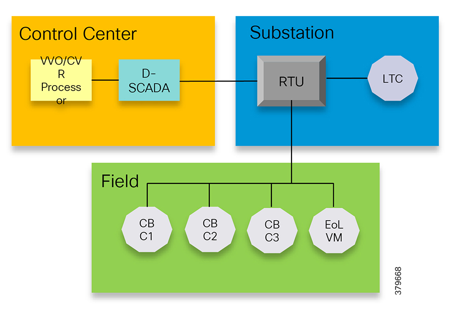
In Figure 6, Volt/VAR and SCADA applications are hosted in the DSO Control Center and RTU and load tap controllers are located in the Secondary Substation. The RTU acts as a outstation device that proxies the poll and/or control command to various field devices like the CBC and end-of-line voltage monitor. This guide covers the use case scenario where the Volt/VAR application flow between IED and SCADA happens via RTU and the distribution feeder type considered is radial. A direct application flow from field devices to the control center for the Volt/VAR use case will be covered in future guides.
Figure 6 Volt/VAR Use Case Block Diagram
The detailed application flow between different actors for power factor regulation is depicted in Figure 7:
Figure 7 Power Factor Regulation

1.![]() Event class data poll to the following devices from RTU:
Event class data poll to the following devices from RTU:
–![]() Substation meter, poll measured Value (Short Floating Point) registers (0 to 4)
Substation meter, poll measured Value (Short Floating Point) registers (0 to 4)
–![]() All CBC(s), poll measured Value (Short Floating Point) (0) and double point command(0)
All CBC(s), poll measured Value (Short Floating Point) (0) and double point command(0)
–![]() End-of-line voltage monitor, poll measured Value (Short Floating Point) register (0)
End-of-line voltage monitor, poll measured Value (Short Floating Point) register (0)
2.![]() The Volt/VAR Optimization processor processes the data received from the devices and makes a control command decision based on the power factor calculation.
The Volt/VAR Optimization processor processes the data received from the devices and makes a control command decision based on the power factor calculation.
3.![]() The control command is sent to RTU via SCADA to CBCs to close the Capacitor Bank Controller N by writing in a Control Relay Output Block (CROB) command register in T104 (IP packet-based IEC-104 protocol).
The control command is sent to RTU via SCADA to CBCs to close the Capacitor Bank Controller N by writing in a Control Relay Output Block (CROB) command register in T104 (IP packet-based IEC-104 protocol).
4.![]() Event class data poll to the following devices from the RTU:
Event class data poll to the following devices from the RTU:
–![]() Substation meter, poll measured Value (Short Floating Point) registers (0 to 4)
Substation meter, poll measured Value (Short Floating Point) registers (0 to 4)
–![]() All CBC(s), poll measured Value (Short Floating Point) (0) and double point command(0)
All CBC(s), poll measured Value (Short Floating Point) (0) and double point command(0)
–![]() End-of-line voltage monitor, poll measured Value (Short Floating Point) register(0)
End-of-line voltage monitor, poll measured Value (Short Floating Point) register(0)
5.![]() All of the above steps are repeated on all the CBCs on the feeder line to maintain a Power Factor value close to 1.
All of the above steps are repeated on all the CBCs on the feeder line to maintain a Power Factor value close to 1.
Figure 8 depicts the detail call flow involved in conservation voltage regulation:
Figure 8 Conservation Voltage Regulation

1.![]() Event class data poll to the below devices from RTU:
Event class data poll to the below devices from RTU:
–![]() Substation meter, poll measured Value (Short Floating Point) registers (0 to 4)
Substation meter, poll measured Value (Short Floating Point) registers (0 to 4)
–![]() All CBC(s), poll measured Value (Short Floating Point) (0) and double point command (0)
All CBC(s), poll measured Value (Short Floating Point) (0) and double point command (0)
–![]() End-of-Line voltage monitor, poll measured Value (Short Floating Point) register (0)
End-of-Line voltage monitor, poll measured Value (Short Floating Point) register (0)
2.![]() The Volt/VAR Optimization processor processes the data received from the devices and makes a control command decision based on the power factor calculation.
The Volt/VAR Optimization processor processes the data received from the devices and makes a control command decision based on the power factor calculation.
3.![]() Control command is sent to RTU via SCADA to the load tap controller to lower/raise LTC by writing in a Control Relay Output Block (CROB) command register in T104.
Control command is sent to RTU via SCADA to the load tap controller to lower/raise LTC by writing in a Control Relay Output Block (CROB) command register in T104.
4.![]() Event class data polls to the following devices from RTU:
Event class data polls to the following devices from RTU:
–![]() Substation meter, poll measured Value (Short Floating Point) registers (0 to 4)
Substation meter, poll measured Value (Short Floating Point) registers (0 to 4)
–![]() All CBC(s), poll measured Value (Short Floating Point) (0) and double point command(0)
All CBC(s), poll measured Value (Short Floating Point) (0) and double point command(0)
–![]() End-of-Line voltage monitor, poll measured Value (Short Floating Point) register (0)
End-of-Line voltage monitor, poll measured Value (Short Floating Point) register (0)
5.![]() The above steps are repeated to maintain a Power Factor value close to 1 along the feeder line.
The above steps are repeated to maintain a Power Factor value close to 1 along the feeder line.
Fault, Location, Isolation, Service Restoration
FLISR Use Case and Benefits
Fault, Location, Isolation, Service Restoration (FLISR) is the process for dealing with fault conditions on the electrical grid. The following occurs as part of this process:
1.![]() Detects (and locates) faults
Detects (and locates) faults
2.![]() Isolates the faults to the smallest segment of the grid possible
Isolates the faults to the smallest segment of the grid possible
3.![]() Restores as much service as possible while the fault is isolated
Restores as much service as possible while the fault is isolated
FLISR includes automatic sectionalizing and restoration and automatic circuit reconfiguration. These applications accomplish DA operations by coordinating operation of field devices, software, and dedicated communication networks in order to automatically determine the location of a fault and rapidly reconfigure the flow of electricity so that some or all of the customers can avoid experiencing outages. Because FLISR operations rely on rerouting power, they typically require feeder configurations that contain multiple paths to single or multiple other substations. This creates redundancies in the power supply for customers located downstream or upstream of a downed power line, fault, or other grid disturbance.
The benefits of FLISR include:
■![]() Consumers experience minimal outage.
Consumers experience minimal outage.
■![]() Utilities improve the System Average Interruption Duration Index (SAIDI) and the System Average Interruption Frequency Index (SAIFI) numbers and avoid financial penalties being levied by the regulator.
Utilities improve the System Average Interruption Duration Index (SAIDI) and the System Average Interruption Frequency Index (SAIFI) numbers and avoid financial penalties being levied by the regulator.
FLISR application control can be implemented in the following modes:
■![]() Supervised Mode—In supervised mode of operation, no automatic control, system delivers information to operator. Operator initiates manual control actions. Restoration time will be longer in this approach. Please refer to the Secondary Substation 1.0 Implementation Guide, which addresses this use case, at the following URL:
Supervised Mode—In supervised mode of operation, no automatic control, system delivers information to operator. Operator initiates manual control actions. Restoration time will be longer in this approach. Please refer to the Secondary Substation 1.0 Implementation Guide, which addresses this use case, at the following URL:
–![]() https://salesconnect.cisco.com/#/search/Secondary%2520Substation%2520Implementation%2520Guide/content
https://salesconnect.cisco.com/#/search/Secondary%2520Substation%2520Implementation%2520Guide/content
■![]() Semi Automatic Mode—A mix of automatic and supervised control is followed. The DA system automatically isolates the fault and performs the restoration part of upstream restoration. The upstream section is between the substation and the faulted section. Manual restoration operation is performed on the downstream section, which is between the fault section and the end of feeder. This guide will address this mode of operation. In this mode, communication happens between IEDs in field to the Distribution Management System (DMS) application residing in control center.
Semi Automatic Mode—A mix of automatic and supervised control is followed. The DA system automatically isolates the fault and performs the restoration part of upstream restoration. The upstream section is between the substation and the faulted section. Manual restoration operation is performed on the downstream section, which is between the fault section and the end of feeder. This guide will address this mode of operation. In this mode, communication happens between IEDs in field to the Distribution Management System (DMS) application residing in control center.
■![]() Fully Automatic Mode—Isolation and restoration happens automatically without any dispatcher intervention. Communication happens directly between a group of associated IEDs. Restoration is very fast (<1 second), but this mode is a complex approach to deploy.
Fully Automatic Mode—Isolation and restoration happens automatically without any dispatcher intervention. Communication happens directly between a group of associated IEDs. Restoration is very fast (<1 second), but this mode is a complex approach to deploy.
How FLISR Works
Figure 9 is divided into four parts (A,B,C, and D) to show how FLISR operations typically work.
■![]() In Part A of Figure 9, the FLISR system locates the fault, typically using line sensors that monitor the flow of electricity, measures the magnitudes of fault currents, and communicates conditions to other devices and grid operators.
In Part A of Figure 9, the FLISR system locates the fault, typically using line sensors that monitor the flow of electricity, measures the magnitudes of fault currents, and communicates conditions to other devices and grid operators.
■![]() Once located, FLISR opens switches on both sides of the fault: one immediately upstream and closer to the source of power supply (Example B of Figure 9), and one downstream and further away (Example C of Figure 9).
Once located, FLISR opens switches on both sides of the fault: one immediately upstream and closer to the source of power supply (Example B of Figure 9), and one downstream and further away (Example C of Figure 9).
■![]() The fault is now successfully isolated from the rest of the feeder. With the faulted portion of the feeder isolated, FLISR next closes the normally open tie switches to neighboring feeders. This re-energizes the unfaulted portion(s) of the feeder and restores services to all customers served by these unfaulted feeder sections from another substation/feeder (Example D of Figure 9).
The fault is now successfully isolated from the rest of the feeder. With the faulted portion of the feeder isolated, FLISR next closes the normally open tie switches to neighboring feeders. This re-energizes the unfaulted portion(s) of the feeder and restores services to all customers served by these unfaulted feeder sections from another substation/feeder (Example D of Figure 9).

FLISR Actors
■![]() Recloser—The circuit recloser is a self-contained device with a necessary monitoring circuit to detect and interrupt over-current conditions and automatically reclose the line.
Recloser—The circuit recloser is a self-contained device with a necessary monitoring circuit to detect and interrupt over-current conditions and automatically reclose the line.
■![]() Sectionalizing Switch or Remote Control Switch—Remote Controller Switches can be load break or fault interrupting devices.
Sectionalizing Switch or Remote Control Switch—Remote Controller Switches can be load break or fault interrupting devices.
■![]() Remote Fault Indicator—Used to detect faults.
Remote Fault Indicator—Used to detect faults.
■![]() Distribution Management System (DMS)—The DMS application residing in the DSO Control Center is an intelligent application, which is the brain of FLISR systems and which performs application circuit reconfiguration logic.
Distribution Management System (DMS)—The DMS application residing in the DSO Control Center is an intelligent application, which is the brain of FLISR systems and which performs application circuit reconfiguration logic.
Figure 10 depicts a parallel feeder distribution system. Two distribution feeders are common out of two different Secondary Substations and each feeder has a recloser associated with it. Remote fault Indicators and remote control switch are distributed across both feeders. RCS3 3 is, by default, an open switch.
Figure 10 FLISR Parallel Feeder
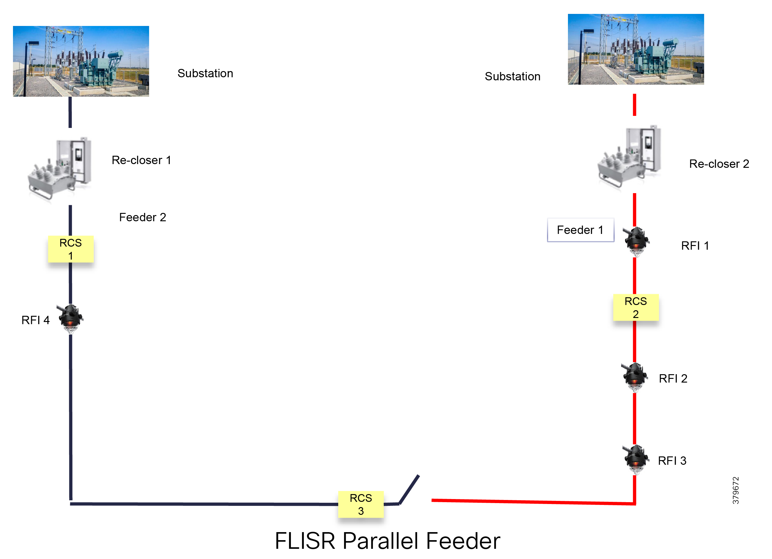
Figure 11 FLISR Application Flow

In Figure 11, the application flow can be observed happening directly from feeder devices to the DMS application in the DSO Control Center. The flow is summarized below:
1.![]() Remote Fault Indicator (RFI) 1 reports to the Distribution Management System (DMS) whenever it encounters a fault.
Remote Fault Indicator (RFI) 1 reports to the Distribution Management System (DMS) whenever it encounters a fault.
2.![]() Recloser2 opens and send a report to DMS when it encounters a temporary fault.
Recloser2 opens and send a report to DMS when it encounters a temporary fault.
3.![]() Recloser2 opens and send a report to DMS when it encounters a permanent fault.
Recloser2 opens and send a report to DMS when it encounters a permanent fault.
4.![]() Remote Control Switch (RCS) 2 reports no voltage status to DMS.
Remote Control Switch (RCS) 2 reports no voltage status to DMS.
5.![]() RCS 2 opens when it encounters faults for second time and send a report to DMS.
RCS 2 opens when it encounters faults for second time and send a report to DMS.
6.![]() DMS issues a close command to the RCS 3.
DMS issues a close command to the RCS 3.
7.![]() DMS initiates a periodic poll (every minute) for the all feeder devices.
DMS initiates a periodic poll (every minute) for the all feeder devices.
8.![]() DMS initiates a solicit periodic poll (every 5 minutes once) for all feeder devices.
DMS initiates a solicit periodic poll (every 5 minutes once) for all feeder devices.
Solution Architecture
This chapter includes the following major topics:
■![]() Distribution Automation Solution Architecture
Distribution Automation Solution Architecture
Places in the Network
The DA Solution is a subset of the Field Area Network (FAN) solution architecture. It follows similar two-tier places in network. The WAN tier connects the control center block with the Secondary Substation block or field area block. In turn, the field area or Secondary Substation blocks connect to utility device blocks via different last mile connectivity methods such as Ethernet, Serial, or Wi-Fi.
Figure 12 Distribution Automation Places in the Network

Control Center Block
The control center block acts as a data center for DSOs, which are used to organize these blocks dedicated for each region (called Regional Network Operating Centers or NOCs). Regional NOCs host various SCADA applications that are needed to perform centralized management for various vertical use cases and which are discussed in Distribution Automation Use Cases. The control center blocks house the HER in clustering mode. As per the Cisco DA solution architecture, the ASR 1000 series of routers will deployed as the HER. The role of the HER is to terminate and aggregate IPSec tunnels from various DA Gateways and SSRs. Additional responsibilities include enforcement of QoS and security policies.
The control center block hosts the IoT Field Network Director (FND), which is a network management system for managing the various gateways. Certificate authorities, which support RSA and elliptic-curve cryptography (ECC) encryption and the AAA server, provide authentication, authorization, and accounting.
For details on the design of the control center, please refer to Cisco FAN-Headend Deep Dive Implementation and FAN Use Cases at the following URL :
■![]() https://salesconnect.cisco.com/open.html?c=da249429-ec79-49fc-9471-0ec859e83872
https://salesconnect.cisco.com/open.html?c=da249429-ec79-49fc-9471-0ec859e83872
The control center security design, with respect to IPS/IDS functionality and application load balancing, will be addressed in detail in upcoming releases. For the current version of the security design, refer to the Cisco Connected Utilities - Field Area Network 2.0 Design and Implementation Guide at the following URL:
■![]() https://www.cisco.com/c/en/us/td/docs/solutions/Verticals/Utilities/FAN/2-0/CU-FAN-2-DIG.html
https://www.cisco.com/c/en/us/td/docs/solutions/Verticals/Utilities/FAN/2-0/CU-FAN-2-DIG.html
Secondary Substation Block
A key component of the Secondary Substation block is the Secondary Substation Router (SSR). Cisco IR1101, IR807, and CGR1120 series routers will be deployed as SSRs, which connect and aggregate traffic from various IEDs and RTUs present in Secondary Substations to single or dual Control Centers.
Field Area Block
The field area block hosts various distribution automation gateways. Cisco IR1101, IR807, and IR809 will be deployed as DA Gateways. Most of the DA Gateways will be installed 1:1 to DA Controllers. DA Gateways will connect primarily to cellular or Ethernet backhaul. DA Gateways are managed from the IoT FND Network Management System (NMS) application residing in the control center block. DA Gateways are deployed in zero touch fashion. Zero Touch Deployment (ZTD) of DA Gateways is discussed in detail in Network Management System. DA Gateways will be provisioned based on application use cases and last mile connectivity to the utility control devices.
Utility Devices Block
The utility devices block hosts various DA controllers such as voltage regulator controllers, recloser controllers, RCSs, and CBCs. These controllers are connected to DA Gateways via Ethernet or serial (RS232, RS485) interfaces.
Distribution Automation Solution Architecture
The Distribution Automation Solution Architecture, which is depicted in Figure 13, is a centralized architecture where the control center, which plays a key role, hosts communication, security, utility, and network management applications. The DSO organizes this control center as a regional DSO NOC that aggregates ICT traffic from different SSRs and Distribution Automation gateways in that region.
The firewall segregates the control center into three zones: the external, DMZ, and internal zones.
–![]() An HER interface, which will be installed in clusters for redundancy and scaling purposes
An HER interface, which will be installed in clusters for redundancy and scaling purposes
–![]() The Registration Authority (RA), which offloads authentication and authorizing functionalities of the CA and leverages the AAA server for authorization
The Registration Authority (RA), which offloads authentication and authorizing functionalities of the CA and leverages the AAA server for authorization
–![]() The Tunnel Provisioning Server (TPS), which is the proxy for the NMS FND
The Tunnel Provisioning Server (TPS), which is the proxy for the NMS FND
■![]() The Internal Zone hosts the Network Time Protocol (NTP), Domain Naming Server (DNS), DHCP, NMS, and Edge Application management using FND, Field Network Director Database (FND-DB), PKI elements like CA, Active Directory, and AAA, and DA applications like SCADA and DMS.
The Internal Zone hosts the Network Time Protocol (NTP), Domain Naming Server (DNS), DHCP, NMS, and Edge Application management using FND, Field Network Director Database (FND-DB), PKI elements like CA, Active Directory, and AAA, and DA applications like SCADA and DMS.
Figure 13 Distribution Automation Solution Architecture

The DA application bidirectional flow can be classified as follows:
1.![]() SCADA <----> RTU <----> IEDs
SCADA <----> RTU <----> IEDs
This section addresses the solution architecture for the above three flows.
SCADA <----> RTU <----> IEDs
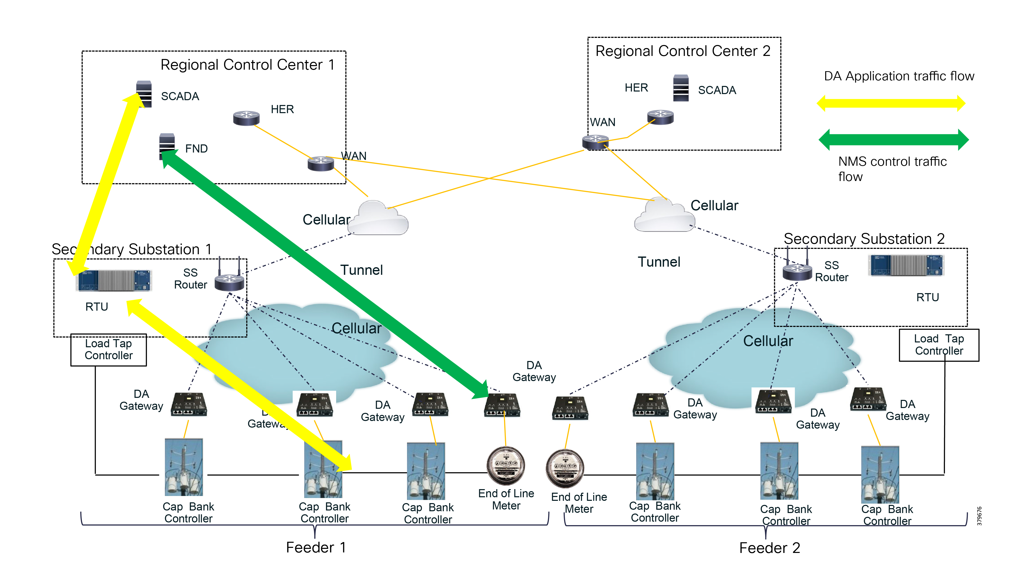
The application bidirectional traffic flow from field IEDs to SCADA in the control center is via RTU, which is located in the Secondary Substation. Application traffic is depicted by the yellow arrow in Figure 14:
Figure 14 SCADA RTU IED Flow DA Design
The ICT solution design for this application flow is as follows:
■![]() DA Gateways, which are installed 1:1 with the controllers and last mile connectivity, will have Ethernet or serial connectivity.
DA Gateways, which are installed 1:1 with the controllers and last mile connectivity, will have Ethernet or serial connectivity.
■![]() DA Gateways will have public WAN connectivity; in most deployment cases, it would be cellular backhaul.
DA Gateways will have public WAN connectivity; in most deployment cases, it would be cellular backhaul.
■![]() Application traffic would be encrypted using FlexVPN. In this architecture. tunnels from the DA Gateways are terminated on the SSR.
Application traffic would be encrypted using FlexVPN. In this architecture. tunnels from the DA Gateways are terminated on the SSR.
■![]() The WAN IP address of the Secondary Substation should be a static (fixed IP) address.
The WAN IP address of the Secondary Substation should be a static (fixed IP) address.
■![]() SSRs route traffic from the IEDs to the RTU, which is co-located.
SSRs route traffic from the IEDs to the RTU, which is co-located.
■![]() RTU processes this application traffic as unsolicited reporting or response to poll/control command.
RTU processes this application traffic as unsolicited reporting or response to poll/control command.
■![]() RTU sends the DA application traffic to the SCADA application in the control center.
RTU sends the DA application traffic to the SCADA application in the control center.
■![]() To transport this application, the SSR will have secure encrypted FlexVPN tunnel to the HER which resides in the control center.
To transport this application, the SSR will have secure encrypted FlexVPN tunnel to the HER which resides in the control center.
For redundancy purposes, two tunnels will be destined to two different regional Control Centers. These tunnels will be designed and deployed active/active tunnels. Separate control traffic will exist from the NMS, i.e., FND to DA Gateways and SSRs. This is depicted by the green arrow in Figure 14. As per this design, DA Gateways will have one FlexVPN tunnel for NMS application traffic and a separate FlexVPN tunnel for application traffic. Similarly, the SSR will have two FlexVPN tunnels to two different regional Control Centers. Application and control traffic can flow through the same FlexVPN tunnel. If required, a third FlexVPN tunnel from SSR to HER can be provisioned for control traffic.
SCADA <----> IEDs
Figure 15 depicts a solution architecture where IEDs can directly communicate with the centralized SCADA. In this design, DA Gateways and SSRs directly connect to HER in the regional control center via public WAN connectivity. For redundancy design, DA Gateways can have two active/active tunnels to two different regional Control Centers. DA application traffic and NMS control traffic can flow in the same FlexVPN tunnel.
Figure 15 SCADA-IED Flow DA Design

Figure 16 depicts the IEC61850 MMS communication flow between SCADA and IEDs:
Figure 16 IEC 61850 MMS Communication Flow with IEDs in Local LAN and Extended LAN

Figure 16 highlights two types of communication flows. One communication flow happens from the control center to the MMS IED located in the local LAN. The second communication flow happens from the control center to the MMS IED located in the Extended LAN (for example, fiber extension to DER sites).
IEDs <----> IEDs
The two types of IED to IED communication are:
Locally-Switched IED Communication
In the case of locally switched IED communication (refer to Figure 17), the IEC61850 Layer 2 GOOSE message flows between the devices located in the substation local LAN and the devices located in the extended LAN. This communication is locally switched at the IR1101 cellular gateway itself rather than being switched at the hub.
Although the communication is locally switched, should there be any requirement to forward the Layer 2 GOOSE message to other substation GOOSE devices, IR1101 could be configured to forward these Layer 2 messages to the Hub (HER) for switching at the hub to other substation devices.
Figure 17 IED-IED Flow Locally-Switched DA Design

In Figure 17, GOOSE messages originate from the Local LAN and are locally switched at the IR1101 Cellular Gateway to the devices located in the Extended LAN.
The LAN extension is facilitated with the introduction of Cisco Industrial Ethernet 2000U series switch, which is connected to SFP port of the IR1101 expansion module. The SFP port of the expansion module is a Layer 2 port, which could be configured as a trunk port allowing both GOOSE VLAN as well as MMS VLAN.
The GOOSE device could be connected to the IE2000U switch. If the connected GOOSE device is capable of VLAN tagging, the interface on IE2000U switch could be configured as trunk port allowing the desired VLAN; additionally, SVI needs to be created for the corresponding VLAN ID. Otherwise, the interface could be configured as an access port to tag the incoming GOOSE traffic with GOOSE VLAN.
As a side note, the interface on the IE2000U switch connecting to the MMS device could be configured as an access port, VLAN tagging the incoming MMS packets with MMS VLAN:
■![]() It is recommended to connect the IE2000U to the GigabitEthernet0/0/5 (SFP port) of the expansion module. This interface could be configured as a trunk port carrying multiple VLANs for Layer 2 GOOSE and Layer3/MMS protocols.
It is recommended to connect the IE2000U to the GigabitEthernet0/0/5 (SFP port) of the expansion module. This interface could be configured as a trunk port carrying multiple VLANs for Layer 2 GOOSE and Layer3/MMS protocols.
■![]() Multiple Layer 2 (bridge) domains could be created by configuring multiple GOOSE VLANs.
Multiple Layer 2 (bridge) domains could be created by configuring multiple GOOSE VLANs.
Should there be any requirement to forward the Layer 2 GOOSE traffic to the GOOSE devices located in other substations, the northbound Layer 2 connectivity to the Hub could be enabled by configuring the L2TPv3 pseudowire on the GOOSE SVI. At the same time, Layer 3 connectivity could be enabled by configuring the IP address on the MMS SVI.
Hub-Switched IED Communication
Layer 2 frames need to be forwarded between multiple GOOSE IEDs connected to multiple IR1101. However, the IR1101s are connected using the Layer 3 cellular network. In order to transport Layer 2 communication over Layer 3 cellular network, an overlay Layer 2 communication infrastructure would be added over the existing secure FlexVPN tunnel.
Figure 18 depicts the solution architecture to enable Layer 2 communication between IEDs over the cellular backhaul. This is achieved with the help of virtual bridge (emulated using hub-and-spoke topology). In Figure 18, the bridging operation is performed in the control center using hub. The DA cellular gateways act as spoke (sending/receiving Layer 2 GOOSE messages). The IEC61850 Layer 2 GOOSE messages sent by an IED connected to one DA gateway are forwarded to the Control Center, where the Layer 2 communication is bridged (to all other GOOSE IEDs) connected to other DA gateways.
Figure 18 IED-IED Flow Hub-Switched DA Design

In Figure 18, GOOSE communication from the leftmost GOOSE device enters the leftmost IR1101, is Layer 2 tunneled inside the L2TPv3 pseudowire to the HER cluster. HER cluster emulates the Layer 2 bridge. Therefore, the Layer 2 GOOSE message is Layer 2 bridged to all other pseudowires down to all the other IR1101s.
L2TPv3 pseudowires are configured over the GOOSE SVI on the IR1101 cellular gateways. The L2TPv3 pseudowire from the IR1101 is terminated on the data center-facing interface of the HER. The Layer 2 frames should be bridged at the HER cluster using an external physical loop (or) using an external switch.
Bridging is performed in the following steps:
1.![]() The GOOSE VLAN tagged frame should be stripped at the hub and is put into a bridge-domain.
The GOOSE VLAN tagged frame should be stripped at the hub and is put into a bridge-domain.
2.![]() The bridge-domain bridges between L2TPv3 pseudowires from multiple cellular gateways.
The bridge-domain bridges between L2TPv3 pseudowires from multiple cellular gateways.
Every IR1101 is configured with an active L2TPv3 pseudowire terminating on one HER. This pseudowire is protected with a backup pseudowire terminating on another HER. In Figure 18, the active pseudowire from the last IR1101 cellular gateway terminates on HER2, and the backup pseudowire terminates on HER4. As the primary pseudowire is down on the last IR1101, the backup pseudowire is UP and active.
Either the primary or the backup pseudowire is active and used at any point in time.
The following sequence captures the Layer 2 IEC 61850 GOOSE message flow from the GOOSE device connected to leftmost IR1101 to GOOSE devices connected to the rest of IR1101s (refer to Figure 18).
Sequence of IEC 61850 GOOSE Bridging Flow
1.![]() 6 x IR1101s in the bottom of Figure 18 are represented from left to right as IR1101-1, IR1101-2, through to IR1101-6. The distribution of pseudowires among the HERs in the cluster is simply for demonstration purposes.
6 x IR1101s in the bottom of Figure 18 are represented from left to right as IR1101-1, IR1101-2, through to IR1101-6. The distribution of pseudowires among the HERs in the cluster is simply for demonstration purposes.
2.![]() The Layer 2 GOOSE message from the first IR1101 goes up to the control center and reaches HER1.
The Layer 2 GOOSE message from the first IR1101 goes up to the control center and reaches HER1.
3.![]() At HER1, the physical loopback link enables Layer 2 bridging. Additionally, the bridge-domain is extended to other HERs by connecting to an external switch. This could even be a virtual switch in cases where CSR1000v is used as the virtual HER.
At HER1, the physical loopback link enables Layer 2 bridging. Additionally, the bridge-domain is extended to other HERs by connecting to an external switch. This could even be a virtual switch in cases where CSR1000v is used as the virtual HER.
4.![]() With the help of the extended Layer 2 bridge-domain, the Layer 2 frame reaches HER2, HER3, and HER4.
With the help of the extended Layer 2 bridge-domain, the Layer 2 frame reaches HER2, HER3, and HER4.
5.![]() HER2 forwards the Layer 2 frame to IR1101-2 over the active pseudowire.
HER2 forwards the Layer 2 frame to IR1101-2 over the active pseudowire.
6.![]() HER3 forwards the Layer 2 frame to IR1101-3 and IR1101-5 over the active pseudowire.
HER3 forwards the Layer 2 frame to IR1101-3 and IR1101-5 over the active pseudowire.
7.![]() HER4 forwards the Layer 2 frame to IR1101-4 over the active pseudowire.
HER4 forwards the Layer 2 frame to IR1101-4 over the active pseudowire.
8.![]() HER4 forwards the Layer 2 frame to IR1101-6 over the backup pseudowire (which is up, because the primary pseudowire is down).
HER4 forwards the Layer 2 frame to IR1101-6 over the backup pseudowire (which is up, because the primary pseudowire is down).
HER as L2TPv3 Hub for Creating Layer 2 Bridge Domain
Figure 19 HER as L2TPv3 Hub for Creating Layer 2 Bridge Domain

The FlexVPN tunnel from IR1101s could terminate on any HER of the cluster. From IR1101, the active pseudowire terminates on one HER, and the backup pseudowire terminates on a different HER. A physical loopback link also occurs on each HER. In addition, every HER is connected to each other using a trunk port, allowing the bridge-domain VLAN (for example, VLAN 1000). The pseudowire is terminated on the data center-facing interface. The connected physical loop interface removes the VLAN tags, and bridges them onto bridge-domain 1000. The trunk port connecting the HERs in the cluster would bridge the VLAN1000 between the HERs in the cluster.
Figure 20, which captures the emulated Layer 2 infrastructure (bridging with hub and spoke), shows the logical view of the hub-and-spoke view of the topology, with HERs acting as hubs and IR1101s acting as spokes. IR1101 (left and middle) has primary L2TPv3 pseudowire in active state. IR1101 (right) has primary L2TPv3 pseudowire in down state, with the secondary pseudowire in UP state taking care of Layer 2 communication.
Figure 20 L2TPv3 Hub and Spoke—Logical View

Figure 21 Encapsulation View (FlexVPN vs L2TPv3 vs Layer 2 vs Layer 3)

In Figure 21, the FlexVPN tunnel is established between the IR1101 cellular gateway and the HER cluster. The L2TPv3 pseudowire is a payload for FlexVPN tunnel. The L2TPv3 pseudowire carries the Layer 2 GOOSE messages between the IR1101 and HER cluster. The GOOSE message is a payload for L2TPv3 tunnel, which, in turn, is a payload for the FlexVPN tunnel. The Layer 2 trunk connecting HER cluster helps in emulating Layer 2 bridging in the control center for enabling IED-to-IED GOOSE communication. On the other hand, IEC61850 MMS messages, T104, MODBUS/IP, and DNP3/IP are all IP-aware protocols, and they could be transmitted as a payload under FlexVPN tunnel directly.
Solution Components
Table 1 lists various solution components and their role and Table 2 lists third party components of the solution.
Cisco IoT Field Network Director with Oracle Database
The Cisco IoT Field Network Director (formerly called Connected Grid Network Management System or CG-NMS) is a software platform that manages the infrastructure for smart grid applications. It provides enhanced Fault, Configuration, Accounting Performance, and Security (FCAPS) capabilities for highly scalable and distributed systems such as smart metering and Distribution Automation. Additional capabilities of Cisco IoT FND include:
■![]() Network topology visualization and integration with the existing Geological Information System (GIS)
Network topology visualization and integration with the existing Geological Information System (GIS)
■![]() Simple, consistent, and scalable network layer security policy management and auditing
Simple, consistent, and scalable network layer security policy management and auditing
■![]() Extensive network communication troubleshooting tools
Extensive network communication troubleshooting tools
■![]() Northbound APIs are provided for utility applications such as Distribution Management System (DMS), Outage Management System (OMS), and Meter Data Management (MDM)
Northbound APIs are provided for utility applications such as Distribution Management System (DMS), Outage Management System (OMS), and Meter Data Management (MDM)
Tunnel Provisioning Server
The TPS acts as a proxy to allow DA Gateways/SSRs to communicate with Cisco IoT FND when they are first deployed in the field. After TPS provisions the tunnels between DA Gateways/SSRs and the HER, the DA Gateways/SSRs can then communicate with Cisco IoT FND directly.
Headend Routers
The primary function of a HER is to aggregate the WAN connections coming from field area routers. HERs terminate the VPN tunnels from the Cisco Connected Grid Routers (CGRs) and may also enforce QoS, profiling (Flexible NetFlow), and security policies. HERs will be deployed in clusters. HER clustering and scale design are discussed in detail in Security, High Availability & Scale.
Registration Authority
The Registration Authority (RA) acts as a proxy to the CA server in the backend for automated certificate enrollment for the SSR and DA Gateways, which must go through the RA and TPS to establish a secure tunnel with the HER. Before this tunnel is established, the device cannot reach the data center network.
A Cisco IOS router can be configured as a Certificate Server-Simple Certificate Enrollment Protocol (SCEP) in RA mode. The Cisco ISR 4400 series of routers are recommended for high scale deployments although ESR5921 (Virtual Router) or any Cisco ISR 4000 series of routers could be chosen to serve the functionality of RA in low scale deployments.
RSA Certificate Authority
The RSA Certificate Authority (CA) provides certificates to network components such as routers and Cisco IoT FND. This solution makes use of the RSA CA within the control center block. Alternatively, an external utility-owned RSA-based CA can be used.
Active Directory
The Active Directory, which is a part of the utility data center and provides directory services, stores identity information for the SSRs and DA Gateways. It provides authentication of the various gateways in the DA solution.
AAA
The Microsoft Network Policy Server (NPS) provides RADIUS-based AAA services for network admission control of SSRs such as CGR 1120 and IR1101 and DA Gateways such as IR807 and IR809. It supports the certificate-base identity authentication used in this solution.
Network Time Protocol Server
Certain services running on the Distribution Automation require accurate time synchronization between the network elements. Many of these applications process a time-ordered sequence of events, so the events must be time stamped to a level of precision that allows individual events to be distinguished from one another and correctly ordered. A Network Time Protocol (NTP) Version 4 server running over the IPv4 and IPv6 network layer can act as a Stratum 1 timing source for the network.
The NTP might deliver accuracies of 10 to 100 milliseconds over the DA solution, depending on the characteristics of the synchronization source and network paths in the WAN.
SSR and DA Gateways
IR1101 Industrial Integrated Services Router
The IR1101 is modular and ruggedized (IP30 specification) platform designed for the utility and machine-to-machine market segment. As part of the Secondary Substation solution, IR1101 can play the role of both SSR and DA Gateway.
For more details, refer to the IR1101 Industrial Integrated Services Router Hardware Installation Guide at the following URL:
■![]() https://www.cisco.com/c/en/us/td/docs/routers/access/1101/hardware/installation/guide/1101hwinst/pview.html
https://www.cisco.com/c/en/us/td/docs/routers/access/1101/hardware/installation/guide/1101hwinst/pview.html
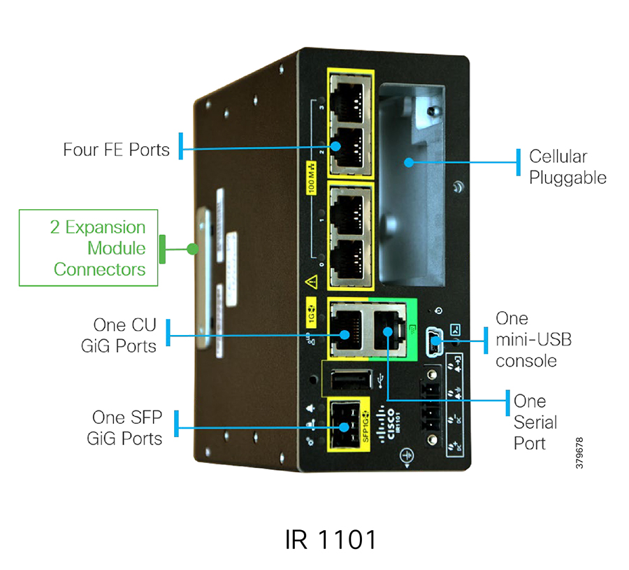
As shown in Figure 22, IR1101 is designed as a modular platform for supporting expansion modules and edge compute modules. IR1101 supports a variety of communication interfaces such as four FE ports, one combo WAN port RS232 DTE port, and LTE modules. The cellular modem is pluggable and a dual SIM card and IPV6 LTE data connection are supported. Raw sockets and protocol translation feature are available.
Expansion Module for IR1101 Industrial Integrated Services Router
The IR1101 provides investment protection. The base module of IR1101 provides a modular pluggable slot for inserting the pluggable LTE module (or) storage module. The expansion module, on the other hand, also comes with a modular pluggable slot for inserting the pluggable LTE module. Overall, two pluggable LTE modules could be inserted on IR1101 (with an expansion module), thus enabling cellular backhaul redundancy with Dual LTE deployments.
Using the expansion module, an additional fiber (SFP) port and an additional LTE port could be added to the capability of IR1101.
The SFP port on the expansion module is the Layer 2 port. Layer 3 is configured through the SVI interface.
Expansion module for dual active LTE, local storage for applications, SFP, and input/output ports |
For more details on the IR1101 expansion module, please refer to the following URL:
■![]() https://www.cisco.com/c/en/us/products/collateral/routers/1101-industrial-integrated-services-router/datasheet-c78-741709.html
https://www.cisco.com/c/en/us/products/collateral/routers/1101-industrial-integrated-services-router/datasheet-c78-741709.html
Connected Grid Router 1120
The CGR 1120 is designed as an indoor model that is well suited for Secondary Substation deployment. CGR 1120 has a rich feature set for utilities and energy verticals. CGR 1120, which acts a SSR in the DA solution, integrates applications like Distributed Energy Resources (DERs) and Secondary Substation monitoring and control. For more details, please refer to the Cisco 1120 Connected Grid Router specification guide at following URL:
■![]() https://www.cisco.com/c/en/us/support/routers/1120-connected-grid-router/model.html
https://www.cisco.com/c/en/us/support/routers/1120-connected-grid-router/model.html
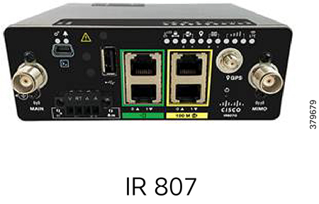
IR807 Industrial Integrated Services Router
The IR807 (see Figure 23) is a compact, ruggedized, lower power, and smart-grid compliant router suited for DA and Secondary Substation deployment. IR807 supports a variety of communication interfaces like Ethernet, serial, and in-built cellular modems to support LTE and 3G networks. Dual SIM support is available for high reliability.
For more details on IR807, please refer to the Cisco 807 Industrial Integrated Services Routers Data Sheet at the following URL:
■![]() https://www.cisco.com/c/en/us/products/collateral/routers/800-series-industrial-routers/datasheet-c78-739643.html
https://www.cisco.com/c/en/us/products/collateral/routers/800-series-industrial-routers/datasheet-c78-739643.html
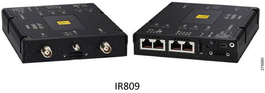
IR809 Industrial Integrated Services Router
The Cisco IR809 (see Figure 24) is a compact, ruggedized router designed for harsh environments. It will well suited for the Distribution Automation and asset management solution. It plays the role of a DA Gateway and has the edge compute capability, which can be used to host the applications to cater to mission-critical or time-sensitive requirements for fast decision making at the edge of IoT network.
For more details on IR809, please refer to the Cisco 809 Industrial Integrated Services Routers Data Sheet at the following URL:
■![]() https://www.cisco.com/c/en/us/products/collateral/routers/809-industrial-router/datasheet-c78-734980.html
https://www.cisco.com/c/en/us/products/collateral/routers/809-industrial-router/datasheet-c78-734980.html
Firewall
A high performance, application-aware firewall with IPS/IDS capability should be installed between the WAN and the head-end infrastructure at the DSO Control Center. The firewall performs inspection of IPv4 and IPv6 traffic from/to the FAN. Its throughput capacity must match the volume of traffic flowing between the application servers and the FANs.
The Cisco Adaptive Security Appliances (ASA) 4150 is recommended. The Cisco ASA 4150 is a high-performance data center security solution. For smaller deployments, low and mid-range firewalls such as the ASA 4110 and the ASA 4120 may be used.
The ASA FirePOWER module may be added for next generation firewall services such as Intrusion Prevention System (IPS), Application Visibility Control (AVC), URL filtering, and Advanced Malware Protection (AMP).
Firewalls can be configured for multiple (virtual) security contexts. For instance, IoT FND servers can be on a different context from infrastructure servers for segmentation. Firewalls are best deployed in pairs to permit failover in case of malfunction.
IEDs
This section describes the following IEDs that were considered during the validation of the Distribution Automation solution:
Capacitor Bank Controller
■![]() Eaton CBC-8000—This Capacitor Bank Controller (CBC) is designed to control capacitor banks installed in distribution feeders. This IED plays a key role in power factor regulation. For details, please refer to the following URL:
Eaton CBC-8000—This Capacitor Bank Controller (CBC) is designed to control capacitor banks installed in distribution feeders. This IED plays a key role in power factor regulation. For details, please refer to the following URL:
–![]() http://www.eaton.com/us/en-us/catalog/utility-and-grid-solutions/cbc-8000-capacitor-bank-control.html
http://www.eaton.com/us/en-us/catalog/utility-and-grid-solutions/cbc-8000-capacitor-bank-control.html
■![]() Beckwith M-6280A Digital Capacitor Bank Control—Digital CBC for Remote Capacitor Automation, Monitoring, and Protection. It supports the Classic Automatic mode of operation that is Voltage, optional VAR Control or optional Current Control. For details, please refer to the following URL:
Beckwith M-6280A Digital Capacitor Bank Control—Digital CBC for Remote Capacitor Automation, Monitoring, and Protection. It supports the Classic Automatic mode of operation that is Voltage, optional VAR Control or optional Current Control. For details, please refer to the following URL:
Recloser Controller
■![]() Beckwith M-7679 R-PAC—Protection, Automation and Control (PAC) System for Recloser, Switch, Sectionalizer, and Advanced Distribution Automation Applications. This is a key component for FLISR use case. For details, please refer to the following URL:
Beckwith M-7679 R-PAC—Protection, Automation and Control (PAC) System for Recloser, Switch, Sectionalizer, and Advanced Distribution Automation Applications. This is a key component for FLISR use case. For details, please refer to the following URL:
Load Tap Controller
■![]() Beckwith M-2001D Tap Changer Control—Digital Tap Changer Control for Transformers and Regulators. This is a key component for conservation voltage regulation use case. For details, please refer to the following URL:
Beckwith M-2001D Tap Changer Control—Digital Tap Changer Control for Transformers and Regulators. This is a key component for conservation voltage regulation use case. For details, please refer to the following URL:
SCADA and Other IED Simulation
■![]() The Triangular Microwave Dynamic Synchronous Transfer Mode (DTM) tool used for DMS (SCADA) and other IEDs like remote control switch, Line Fault Indicator. Used for automated testing of RTUs, IEDs, gateways, and SCADA systems. For details, please refer to an overview of DTM at the following URL:
The Triangular Microwave Dynamic Synchronous Transfer Mode (DTM) tool used for DMS (SCADA) and other IEDs like remote control switch, Line Fault Indicator. Used for automated testing of RTUs, IEDs, gateways, and SCADA systems. For details, please refer to an overview of DTM at the following URL:
–![]() http://www.trianglemicroworks.com/products/testing-and-configuration-tools/dtm-pages/overview
http://www.trianglemicroworks.com/products/testing-and-configuration-tools/dtm-pages/overview
RTU
■![]() Eximprod ES 200 is Virtual RTU. This RTU application can be hosted as a docker application on Cisco edge compute platforms like IR809 and IR1101. For more details on ES200, refer to the following URL:
Eximprod ES 200 is Virtual RTU. This RTU application can be hosted as a docker application on Cisco edge compute platforms like IR809 and IR1101. For more details on ES200, refer to the following URL:
–![]() http://www.epg.ro/wp-content/uploads/2017/09/ES200-Datasheet-public.pdf
http://www.epg.ro/wp-content/uploads/2017/09/ES200-Datasheet-public.pdf
■![]() For Virtual RTU implementation, please refer to the Connected Utilities Virtual RTU Implementation Guide at the following URL:
For Virtual RTU implementation, please refer to the Connected Utilities Virtual RTU Implementation Guide at the following URL:
–![]() https://www.cisco.com/c/en/us/td/docs/solutions/Verticals/Utilities/FAN/Virtual-RTU/IG/CU-VRTU-IG/CU-VRTU-IG.html
https://www.cisco.com/c/en/us/td/docs/solutions/Verticals/Utilities/FAN/Virtual-RTU/IG/CU-VRTU-IG/CU-VRTU-IG.html
Design Considerations
This chapter includes the following major topics:
IP Address Schema
The IP Address Schema is discussed in a combination of the following multiple options:
■![]() Addressing at various layers of the solution
Addressing at various layers of the solution
■![]() Types of network involved (Underlay Network vs Overlay Network):
Types of network involved (Underlay Network vs Overlay Network):
–![]() Underlay network—Service provider-assigned addresses used in establishment of tunnel
Underlay network—Service provider-assigned addresses used in establishment of tunnel
–![]() Overlay network—Reachable only after a secure overlay network path is established
Overlay network—Reachable only after a secure overlay network path is established
■![]() Choice of network layer protocol (IPv4 vs IPv6 vs Dual Stack)
Choice of network layer protocol (IPv4 vs IPv6 vs Dual Stack)
■![]() Mode of address assignment (Static vs Dynamic)
Mode of address assignment (Static vs Dynamic)
Note: SSRs and DA Gateways shall be referred to as IoT Gateways in the abstract context in this document.
Figure 25 IP Address Schema—Addressing at Various Layers of the Solution

Figure 25 serves as the reference base for the discussion of IP address schema used in this solution.
Overlay versus Underlay Network
Since the WAN is a highly unsecure network, the communication path between the DA Gateways/SSRs and the HERs have to be secured with FlexVPN tunnels.
■![]() The Underlay Network is the name of the underlying public network over which the tunnels are established.
The Underlay Network is the name of the underlying public network over which the tunnels are established.
■![]() Once the tunnels are established, any network connectivity established as an overlay on top of the already established tunnel is called an Overlay Network.
Once the tunnels are established, any network connectivity established as an overlay on top of the already established tunnel is called an Overlay Network.
As an example, with reference to Figure 26, the FlexVPN tunnel can be established between the public IP of the DA Gateway (located in the Distribution Network) and the DMZ Virtual IP of the HER Cluster (located in the Utility Public Network). Once the tunnel is established, reachability information of FND and SCADA (located in the Utility Private Network) could be advertised as overlay routes through the tunnel to the DA Gateway.
Figure 26 FlexVPN Tunnels, Underlay vs Overlay Networks

■![]() Both IPv4 and IPv6 are supported Overlay/Underlay IP addresses in this solution.
Both IPv4 and IPv6 are supported Overlay/Underlay IP addresses in this solution.
■![]() The term IP is used to represent both IPv4 and IPv6 addresses throughout the document unless explicitly called out.
The term IP is used to represent both IPv4 and IPv6 addresses throughout the document unless explicitly called out.
In Figure 26, the public IP of the HER cluster and the DA Gateways are used in establishing the FlexVPN Tunnel. They are Underlay IP addresses.
The following list includes Overlay IP addresses:
–![]() IP address of the Loopback interface on HER
IP address of the Loopback interface on HER
–![]() IP address of the Utility Private Network components (such as SCADA, FND, and application servers)
IP address of the Utility Private Network components (such as SCADA, FND, and application servers)
–![]() These routes are advertised through the tunnel towards the IoT Gateway
These routes are advertised through the tunnel towards the IoT Gateway
■![]() Advertised by the IoT Gateway:
Advertised by the IoT Gateway:
–![]() IP address of the Loopback interface on the gateway
IP address of the Loopback interface on the gateway
–![]() Optionally, locally connected devices on IoT Gateway can be advertised
Optionally, locally connected devices on IoT Gateway can be advertised
–![]() These routes are advertised through the tunnel towards the HER Cluster
These routes are advertised through the tunnel towards the HER Cluster
Table 8 captures the distinction between the usage of underlay address at different points in the solution..
■![]() Underlay IP addresses on the HER cluster have to be static IP addresses (IPv4 and/or IPv6).
Underlay IP addresses on the HER cluster have to be static IP addresses (IPv4 and/or IPv6).
■![]() As long as the tunnel is up, overlay routes to Utility Private Network components like FND and SCADA, would be reachable on the SSR or DA Gateway.
As long as the tunnel is up, overlay routes to Utility Private Network components like FND and SCADA, would be reachable on the SSR or DA Gateway.
■![]() Overlay IPv4 and IPv6 reachability is agnostic to the underlying network layer. In other words, both IPv4 and IPv6 overlay reachability can be enabled between SCADA masters and outstations over an underlay network, which can be IPv4-only or IPv6-only or Dual-stack.
Overlay IPv4 and IPv6 reachability is agnostic to the underlying network layer. In other words, both IPv4 and IPv6 overlay reachability can be enabled between SCADA masters and outstations over an underlay network, which can be IPv4-only or IPv6-only or Dual-stack.
Loopback Addressing Design
With the WAN IP address (Underlay address) allocated dynamically to the IoT Gateway, this address could possibly change every time the device disconnects and reconnects. Therefore, the mechanism for uniquely identifying the IoT Gateway is allocating an Overlay IP address to the gateway's loopback interface, with a permanent lease from the DHCP server located in the communication headend of the Utility Private Network. Both IPv4 and IPv6 Overlay addresses can be configured on the loopback interface of the IoT Gateway. This configuration is taken care of dynamically by Cisco IoT FND during ZTD.
Considering that the IoT Gateways are aggregated at the HER cluster, the Overlay IP addresses that are to be allocated to the loopback interface of the gateways are chosen from the same IPv4 and IPv6 DHCP pool to which the HER Loopback interface's IPv4/IPv6 belongs.
Note: Although the gateways and HERs share the same IPv4 and IPv6 subnets while configuring loopback interfaces, the recommendation is to use a subnet mask of /32 for IPv4 and /128 for IPv6 addresses.
Figure 27 captures the loopback addressing design used in this solution.
Figure 27 IP Address Schema—Loopback Addressing on HER Cluster and IoT Gateways

For example, if 192.168.150.0/24 and 2001:db8:baba:face::/64 are the subnet chosen for representing the SSRs and DA Gateways:
■![]() Few IP addresses of this subnet are reserved for loopback interface configuration on HERs. These addresses are statically assigned on HERs. For example, the following addresses, as shown in Figure 27, can be reserved for HERs:
Few IP addresses of this subnet are reserved for loopback interface configuration on HERs. These addresses are statically assigned on HERs. For example, the following addresses, as shown in Figure 27, can be reserved for HERs:
–![]() IPv4 addresses 192.168.150.1, 192.168.150.2 and 192.168.150.3
IPv4 addresses 192.168.150.1, 192.168.150.2 and 192.168.150.3
–![]() IPv6 addresses 2001:db8:baba:face::1, 2001:db8:baba:face::2 and 2001:db8:baba:face::3
IPv6 addresses 2001:db8:baba:face::1, 2001:db8:baba:face::2 and 2001:db8:baba:face::3
These reserved addresses must be excluded from the DHCP pool meant for Overlay address allocation to SSRs and DA Gateways.
Note: These loopback addresses are to be allocated with permanent lease by the DHCP server (IPv4 and IPv6).
The allocated loopback IP addresses (with permanent lease) would serve the purpose of uniquely representing the DA Gateway to Cisco IoT FND, as well as SCADA and other application servers located in the Utility Private Network.
Note: The tunnel aggregation point has to have a statically-configured IP address.
Utility Private Network
The Utility Private Network aligns with the headend block shown in Places in the Network. Utility Private Networks, which are comprised of the components residing in the protected data center part of the network, have the following sub blocks:
■![]() Private network portion of the communication headend
Private network portion of the communication headend
Note: All the components located in the Utility Private Network fall under the overlay network category. FND, SCADA, DHCP Server, Certificate Authority, Active Directory, and AAA server are among the components that are part of this Utility Private Network.
Of all these private network components, the reachability information of only selected components like FND and SCADA need to be advertised as overlay routes to the IoT Gateways. All components need not be advertised to the IoT Gateways.
The Utility Private Network layer interacts with the rest of the layers by interfacing with the Utility Public Network components such as the RA, TPS, and HER Cluster.
Private Network Portion of the Communication Headend
Table 9 captures the list of components located in the Private Network portion of the communication headend, its mode of IP address configuration, the single/dual stack requirement, and the requirement to be advertised as an overlay route to the IoT Gateway.
| Should it be advertised to the IoT Gateway as overlay route? |
|||
|---|---|---|---|
FND will interact with DHCP server within Utility Private Network. |
|||
Utility Control Center
Table 10 captures the list of components located in the Utility Control Center part of the headend, its mode of IP address configuration, the single/dual stack requirement, and the requirement to be advertised as an overlay route to the IoT Gateway.
| Should it be advertised to the IoT Gateway as overlay route? |
|||
|---|---|---|---|
According to what the control center application server supports |
Utility PKI
Table 11 captures the list of components located in the Utility PKI part of the headend, its mode of IP address configuration, the single/dual stack requirement, and the requirement to be advertised as an overlay route to the IoT Gateway.
| Should it be advertised to the IoT Gateway as overlay route? |
|||
|---|---|---|---|
As the IoT Gateway can receive the certificate with the help of the RA, the route for the CA does not need be advertised to the IoT Gateway.
Utility Public Network
The Utility Public Network aligns with the headend block shown in Places in the Network.
Utility Public Networks are comprised of publicly-exposed network portions of the communication headend and are typically positioned under the DMZ. This network portion of the communication headend handles the communication from IoT Gateways located in the Secondary Substation (or) Distribution Network.
The Utility Public Network has the following sub-block:
■![]() The DMZ Network portion of the Communication headend, which includes:
The DMZ Network portion of the Communication headend, which includes:
Both SSRs and DA Gateways should be able to reach the RA, TPS, and HERs.
As Figure 28 shows, Utility Public Networks are comprised of TPS, HER Clustering, and RA, which interact with the (underlay) WAN in the southbound. Utility Public Networks also interact with the Utility Control Center, PKI, and the communication headend in the northbound.
Figure 28 Utility Public Network—IP Addressing, Advertised Overlay Addresses

Note: The HER Cluster can serve as the default gateway for all the Utility Private Network components, including Utility Control Center, Utility PKI, and communication headend private network.
■![]() DMZ IPs 1-6 are underlay public IP addresses, and should already be reachable from IoT Gateways.
DMZ IPs 1-6 are underlay public IP addresses, and should already be reachable from IoT Gateways.
■![]() Overlay routes to be advertised, once the FlexVPN Tunnel is established, include:
Overlay routes to be advertised, once the FlexVPN Tunnel is established, include:
–![]() IPv4 and IPv6 addresses of SCADA from the control center
IPv4 and IPv6 addresses of SCADA from the control center
–![]() IPv4 and IPv6 addresses of FND from the communication headend
IPv4 and IPv6 addresses of FND from the communication headend
–![]() IPv4 and IPv6 addresses of loopback interfaces of the HER routers in the clusters
IPv4 and IPv6 addresses of loopback interfaces of the HER routers in the clusters
–![]() IP addresses of any other application server that needs to be advertised to the IoT Gateways
IP addresses of any other application server that needs to be advertised to the IoT Gateways
–![]() IP addresses of DHCP server, if there is any requirement of IoT Gateway to act as DHCP relay
IP addresses of DHCP server, if there is any requirement of IoT Gateway to act as DHCP relay
Table 12 captures the list of components located in the Utility Public Network of the headend, and its mode of IP address configuration, the single/dual stack requirement, and requirement to be advertised as an overlay route to the IoT Gateway.
Wide Area Network
DA Cellular leverages the Wide Area Network (WAN) for connecting the headend block with the substation (or) DA blocks. The solution uses WAN as an underlay network. IP backhaul categories can be IPv4-only or IPv6-only or dual-stack serving both IPv4 and IPv6 at the same time.
Secondary Substation
IP addressing of the SSR would be very similar to IP addressing on the DA Gateway. The difference comes only if a utility requirement exists for aggregating the communication from multiple DA Gateways at the SSR, instead of aggregating directly at the DSO headend.
Note: If the SSR needs to aggregate tunnels from multiple DA Gateways, then static WAN IP addresses are recommended on the SSRs.
As shown in Figure 29, the SSR could serve RTU, IPv4 IED, and IPv6 IED:
Figure 29 IP Addressing in SSR—Dynamic Public IP Address

WAN IP could be a dynamically-allocated public IP, which could change every time the SSR disconnects and reconnects to the network. The SSR is uniquely represented by its IPv4 and IPv6 loopback addresses. The loopback addresses are configured on the SSR by Cisco IoT FND during ZTD. Static WAN IP also would work perfectly fine in this scenario.
The IPv4 and IPv6 devices can be advertised to the DSO headend using its configured IP addresses or could be Network Address Translated (NAT’d) to the IP address of the SSR to keep a simple and consistent routing information. More about this is discussed under Network Address Translation.
Any legacy (serial interface based) Secondary Substation device could also be enabled for communication with the DSO headend with the use of raw sockets (or) protocol translation services, provided by the SSR.
Figure 30 portrays the scenario where the DA Gateways are aggregated at the SSR. In this case, the SSR must have a STATIC Public IP to handle the termination of tunnels from the DA Gateways. The loopback address configuration and enabling access to IPv4 and IPv6 IEDs are similar to the previous section.
Figure 30 IP Addressing in SSR—Static Public IP Address

In addition to advertising the routes to the DSO headend, the SSR could choose to selectively advertise a subset of the routes in the southbound direction to the DA Gateways.
| Should it be advertised to the DSO headend and DA Gateways (as overlay route)? |
|||
|---|---|---|---|
It depends. Not required if the IED IP addresses are NAT'd by the SSR's IP address. |
Distribution Network
DA Gateways in the field would receive their WAN IP addresses (IPv4 and/or IPv6) dynamically from the service provider. This is an underlay IP address, which is used for forming the FlexVPN Tunnel.
As Figure 31 shows, the DA Gateway could serve IPv4 IED, IPv6 IED, and also serial devices, and enable overlay communication with the DSO headend components such as FND and SCADA:
Figure 31 IP Addressing in DA Gateway

The IPv4 and IPv6 IEDs can be advertised to the DSO headend, using the IED’s configured IP addresses (or) could be NAT’d to the IP address of the DA Gateway to keep a simple and consistent routing information. More about this is discussed in Network Address Translation.
The DA Gateway is uniquely represented by its IPv4 and IPv6 loopback addresses. The loopback addresses are configured on the DA Gateway by Cisco IoT FND as part of ZTD.
Figure 31 on the previous page shows the FlexVPN Tunnel established between the DA Gateway and the HER Cluster of the DSO headend. If the utility requires aggregating multiple DA Gateways at the substation level, the DA Gateway could establish an additional tunnel with the SSR.
| Should it be advertised to the DSO headend (as overlay route)? |
|||
|---|---|---|---|
Not required if the IED IP addresses are NAT'd with the DA Gateway's IP address. |
Summary of IP Address Allocation Methods
Table 16 captures the summary of the various IP addressing components, the location in which the component exists, and the method of address allocation:
Loopback addresses of HER1, HER2, and HER3 are one-time manual configurations on the Utility Public Network.
Loopback addresses of SSRs as well as DA Gateways are dynamically configured by Cisco IoT FND during the ZTD. The DHCP (IPv4 and IPv6) pool chosen for this address allocation is the pool to which the HER loopback addresses belongs.
Network Services
WAN
The WAN tier connects the Field Area and Secondary Substation blocks with the control center. The following are some considerations while choosing the technology for the WAN backhaul and its routing protocols:
■![]() Scalability evaluation: The WAN must cater to the aggregation routers located in the control center and the SSRs/DA Gateways in the DA, and to support the multitude of IP tunnels between them. Dual tunnel configuration should be accounted for in order to support resiliency
Scalability evaluation: The WAN must cater to the aggregation routers located in the control center and the SSRs/DA Gateways in the DA, and to support the multitude of IP tunnels between them. Dual tunnel configuration should be accounted for in order to support resiliency
■![]() Redundancy and high availability as per SLAs
Redundancy and high availability as per SLAs
■![]() Dual stack routing protocols supported by Cisco IOS, such as MP-BGP, OSPFv3, RIPv2/RIPng, EIGRP, static routes, and IKEv2 prefix injection from FlexVPN
Dual stack routing protocols supported by Cisco IOS, such as MP-BGP, OSPFv3, RIPv2/RIPng, EIGRP, static routes, and IKEv2 prefix injection from FlexVPN
■![]() Leverage existing WAN infrastructure connecting to the Control Centers
Leverage existing WAN infrastructure connecting to the Control Centers
■![]() Topology considerations such as hub-and-spoke configurations
Topology considerations such as hub-and-spoke configurations
■![]() Static versus dynamic routing
Static versus dynamic routing
■![]() Convergence time when loosing connectivity with the HER or the SSR
Convergence time when loosing connectivity with the HER or the SSR
■![]() Latency and bandwidth requirements depending on traffic flow patterns
Latency and bandwidth requirements depending on traffic flow patterns
■![]() Minimize the control traffic over WAN
Minimize the control traffic over WAN
Security, High Availability & Scale discusses WAN backhaul redundancy in detail.
Cellular Backhaul
Cellular backhaul will be the most prevalent deployment backhaul and Cisco IR1101 is the correct choice for deploying as a SSR and as a DA Gateway. However, Cisco IR807 could be deployed in cases where lower cost and lower power consumption are the primary requirements.
Cisco IR1101 supports two 4G LTE modules to support cellular backhaul deployment with backhaul redundancy. Most European carriers will be operating in FDD Bands 3, 7, and 20. These bands are well supported by the Cisco IR1101 LTE modem. For more details about other supported TDD LTE, UMTS, HSPA+ and HSPA bands, please refer to Cisco IR1100 product specification document.
Other important features supported by IR1101 LTE modules include:
■![]() Dual SIM, which allows SIM to be active in either slot; failover to the alternative SIM slot if the active SIM loses connectivity to the network
Dual SIM, which allows SIM to be active in either slot; failover to the alternative SIM slot if the active SIM loses connectivity to the network
■![]() Dual LTE, which allows primary SIM to be inserted in the LTE module of IR1101 base unit; secondary SIM could also be inserted in the LTE module of IR1101 expansion module
Dual LTE, which allows primary SIM to be inserted in the LTE module of IR1101 base unit; secondary SIM could also be inserted in the LTE module of IR1101 expansion module
■![]() Auto SIM mode, which will automatically select the right carrier after a SIM slot switching and automatically reset the modem
Auto SIM mode, which will automatically select the right carrier after a SIM slot switching and automatically reset the modem
■![]() SIM Online Insertion and Removal (OIR)
SIM Online Insertion and Removal (OIR)
■![]() SIM lock and unlock capabilities
SIM lock and unlock capabilities
■![]() IPV6 protocol is supported on the cellular interface to enable LTE IPV6 data connection
IPV6 protocol is supported on the cellular interface to enable LTE IPV6 data connection
IP Tunnels
If Distribution Automation traffic traverses any kind of public WAN, data should be encrypted with standards-based IPSec. This approach is advisable even if the WAN backhaul is a private network. A site-to-site IPSec VPN can be built between the DA Gateway/SSR and the HER in the control center. The Cisco Distribution Automation solution implements a sophisticated key generation and exchange mechanism for both link-layer and network-layer encryption. This significantly simplifies cryptographic key management and ensures that the hub-and-spoke encryption domain not only scales across thousands of field area routers, but also across thousands of DA Gateways and SSRs.
IP tunnels are a key capability for all DA use cases forwarding various traffic types over the backhaul WAN infrastructure. Various tunneling techniques may be used, but it is important to evaluate the individual technique's OS support, performance, and scalability for the DA Gateway/SSR and HER platforms.
The following are tunneling considerations:
■![]() IPSec Tunnel—To protect the data integrity of all traffic over the unsecure WAN. The IPSec GRE tunnel could be established over the IPv4-only WAN infrastructure or Native IPv6/Dual-Stack WAN infrastructure.
IPSec Tunnel—To protect the data integrity of all traffic over the unsecure WAN. The IPSec GRE tunnel could be established over the IPv4-only WAN infrastructure or Native IPv6/Dual-Stack WAN infrastructure.
■![]() Communication with IPv6 IEDs could be securely transported as an overlay traffic through the IPv4 or IPv6 GRE Tunnel, secured with IPSec.
Communication with IPv6 IEDs could be securely transported as an overlay traffic through the IPv4 or IPv6 GRE Tunnel, secured with IPSec.
In Figure 32, the underlay IPSec Tunnel could be established over an IPv4-only/IPv6-only/Dual-stack WAN infrastructure. It could carry communication to both IPv4 and IPv6 IEDs in a secure manner.
Figure 32 Tunnel between the DA Gateway/SS Router and the HER
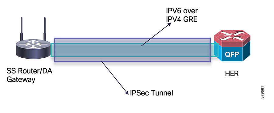
FlexVPN
FlexVPN is a flexible and scalable VPN solution based on IPSec and IKEv2. To secure DA data communication with the headend across the WAN, FlexVPN is recommended. The IoT FND establishes FlexVPN tunnels between the HERs and the DA Gateways as a part of the ZTD process.
FlexVPN, which integrates various topologies and VPN functions under one framework, simplifies the deployment of VPNs by providing a unified VPN framework that is compatible with legacy VPN technologies.
FlexVPN has some of the following benefits:
■![]() Allows use of a single tunnel for both IPv4 and IPv6, when the medium supports it
Allows use of a single tunnel for both IPv4 and IPv6, when the medium supports it
■![]() Supports QoS in both directions: hub-to-spoke and spoke-to-hub
Supports QoS in both directions: hub-to-spoke and spoke-to-hub
■![]() Supports Virtual Routing and Forwarding (VRF)
Supports Virtual Routing and Forwarding (VRF)
■![]() Reduces control plane traffic for costly links with support for tuning of parameters
Reduces control plane traffic for costly links with support for tuning of parameters
Note: In this solution, IPSec is configured in the tunnel mode.
■![]() IKEv2 has fewer round trips in a negotiation than IKEv1: two round trips versus five for IKEv1 for a basic exchange
IKEv2 has fewer round trips in a negotiation than IKEv1: two round trips versus five for IKEv1 for a basic exchange
■![]() Built-in dead peer detection (DPD)
Built-in dead peer detection (DPD)
■![]() Built-in configuration payload and user authentication mode
Built-in configuration payload and user authentication mode
■![]() Built-in NAT traversal (NAT-T). IKEv2 uses ports 500 and 4500 for NAT-T
Built-in NAT traversal (NAT-T). IKEv2 uses ports 500 and 4500 for NAT-T
■![]() Improved re-keying and collision handling
Improved re-keying and collision handling
■![]() A single Security Association (SA) can protect multiple subnets, which improves scalability. Support for Multi-SA Dynamic Virtual Tunnel Interfaces (DVTI) support on the hub.
A single Security Association (SA) can protect multiple subnets, which improves scalability. Support for Multi-SA Dynamic Virtual Tunnel Interfaces (DVTI) support on the hub.
■![]() Asymmetric authentication in site-to-site VPNs, where each side of a tunnel can have different pre-shared keys, different certificates, or on one side a key and the other side a certificate
Asymmetric authentication in site-to-site VPNs, where each side of a tunnel can have different pre-shared keys, different certificates, or on one side a key and the other side a certificate
In the FlexVPN model, the HER acts as the FlexVPN hub and the DA Gateways act as the FlexVPN spokes. The tunnel interfaces on the DA Gateways acquire their IP addresses from address pools configured during ZTD. These addresses only have local significance between the HER and the DA Gateways. Since the DA Gateway's tunnel addresses are both dynamic and private to the HER, NMS must address the DA Gateways by their loopback interface in this network architecture. Conversely, the DA Gateway sources its traffic using its loopback interface.
Before the FlexVPN tunnel is established, the DA Gateway can only communicate to the HER in the headend network. This is done over the WAN backhaul via a low priority default route. During FlexVPN handshake, route information is exchanged between the HER and the DA Gateway. The DA Gateway learns the headend routes (IPv4 and IPv6) through FlexVPN.
Figure 33 FlexVPN Hub-and-Spoke
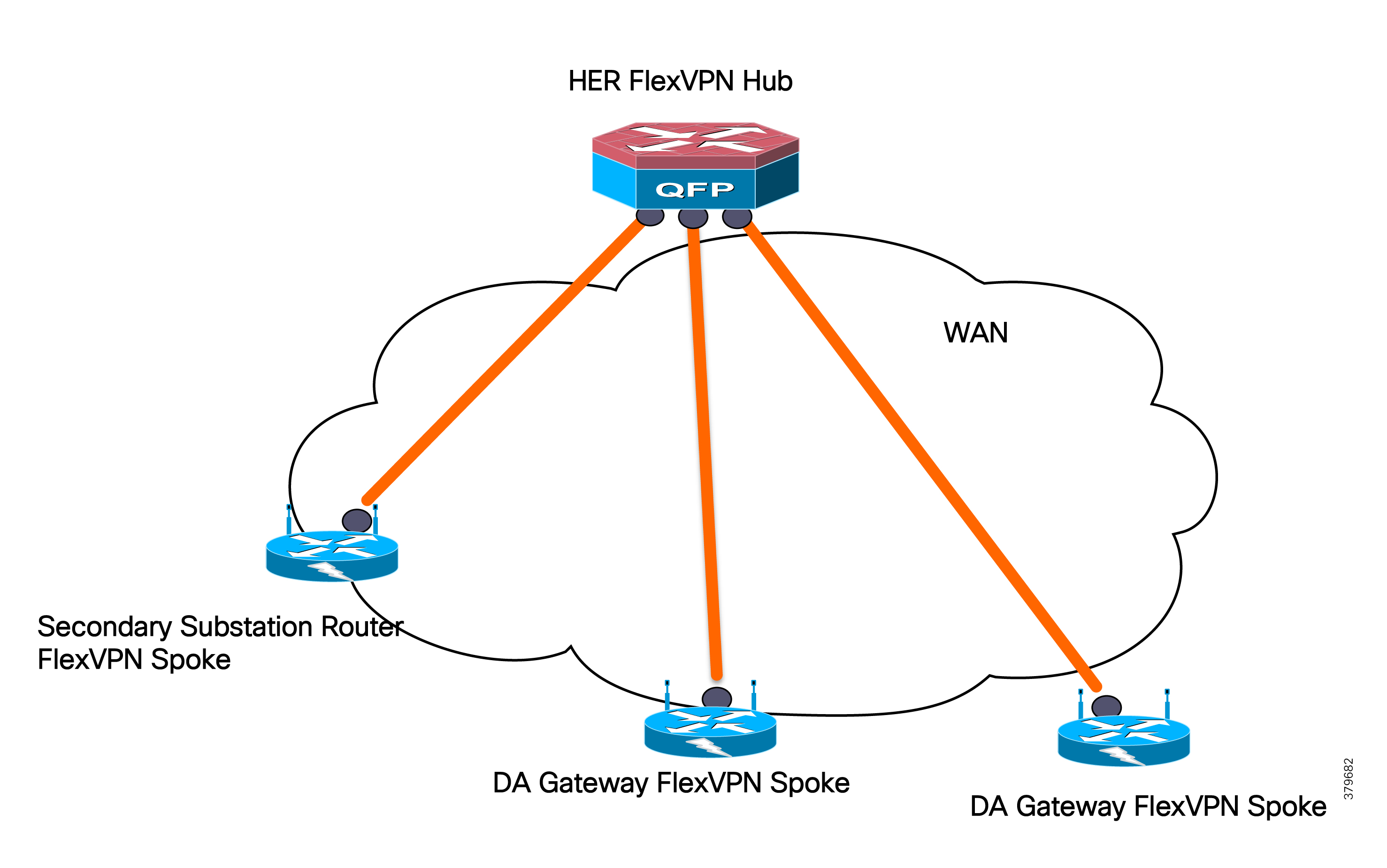
In this release, only the FlexVPN hub-and-spoke design is discussed. Spoke-to-spoke ICT design will be needed for IED-to-IED application traffic flow deployment scenarios.
FlexVPN versus DMVPN Selection Criteria
FlexVPN has advantages over DMVPN primarily when the cost of the WAN links is based on volume of data flowing between the hub and the spokes. The reasons for this include:
■![]() Dynamic routing is not necessary, as the Internet Key Exchange v2 (IKEV2) prefix injection for IPv4 and IPV6 is supported.
Dynamic routing is not necessary, as the Internet Key Exchange v2 (IKEV2) prefix injection for IPv4 and IPV6 is supported.
■![]() IPv6 is available and this reduces control plane traffic, while dynamic IPv4 and IPv6 routing cannot be avoided in DMVPN. Note that with FlexVPN, prefixes are only injected when the tunnel is being established.
IPv6 is available and this reduces control plane traffic, while dynamic IPv4 and IPv6 routing cannot be avoided in DMVPN. Note that with FlexVPN, prefixes are only injected when the tunnel is being established.
■![]() Next Hop Resolution Protocol (NHRP) is not used between the hub and the spoke, reducing control plane traffic, while in DMVPN, NHRP is required between the hub and the spoke.
Next Hop Resolution Protocol (NHRP) is not used between the hub and the spoke, reducing control plane traffic, while in DMVPN, NHRP is required between the hub and the spoke.
■![]() Specific QoS rules can be dedicated to each side of the channels, while in DMVPN, the same QoS rules applied to all channels in the downstream (hub and spokes) direction
Specific QoS rules can be dedicated to each side of the channels, while in DMVPN, the same QoS rules applied to all channels in the downstream (hub and spokes) direction
■![]() NAT/PAT can be configured on both sides of the hub and the spoke.
NAT/PAT can be configured on both sides of the hub and the spoke.
■![]() Clustering of the hubs can be done in different ways, allowing various redundancy scenarios.
Clustering of the hubs can be done in different ways, allowing various redundancy scenarios.
■![]() IKEV2 tunnel allows switching tunnel across physical interfaces.
IKEV2 tunnel allows switching tunnel across physical interfaces.
IKEV2 supports snapshot-based routing, which can be used in the case of the mesh network at the southbound traffic.
If the connectivity between the hub and the SSR is over cellular, then these protocols will consume data from a service provider. If no data limit exists, these protocols are suitable and can be used without any problem. But if there is a limit (such as 1GB/month) on the service provider-provided data, then the exchange packets between the protocol processes on the routers will exceed the limit and might incur an additional cost (depending on the service provider).
With FlexVPN, these protocols are not necessary. Prefix-based injection and snapshot-based routing are more preferred with FlexVPN. No control packet exchanges occur between the hub and the SSR. With this design, the service provider's monthly or the daily limit is sufficient, and the customer can expect a lower overhead cost than the cost incurred when DMVPN is implemented with the above-mentioned dynamic routing protocols.
Therefore, FlexVPN-based implementation is preferred over DMVPN-based implementation. DMVPN can also be considered if the service provider does not have a limit on data consumption.
IP Routing
For most deployment in the European region, cellular backhaul will be considered as the primary backhaul. FlexVPN IKEV2-based prefix injection is the recommended design for IP routing. This approach will ensure minimization of control traffic over the WAN (by saving approximately 100 MB or more of control traffic every month), and, in turn, the saved data is available for application traffic.
The “value add” in this type of routing is the total cost of ownership (TCO) control achieved. As soon as the tunnel is provisioned between the DA Gateway or SSR and the HER is provisioned as part of Zero Touch Provisioning using IoT FND, IED prefixes from the field area/Secondary Substation block will be advertised to HER and SCADA prefixes will be advertised to the DA Gateways/SSRs after tunnel establishment. This is depicted in Figure 34:
Figure 34 Routing via IKEv2 Prefix Injection
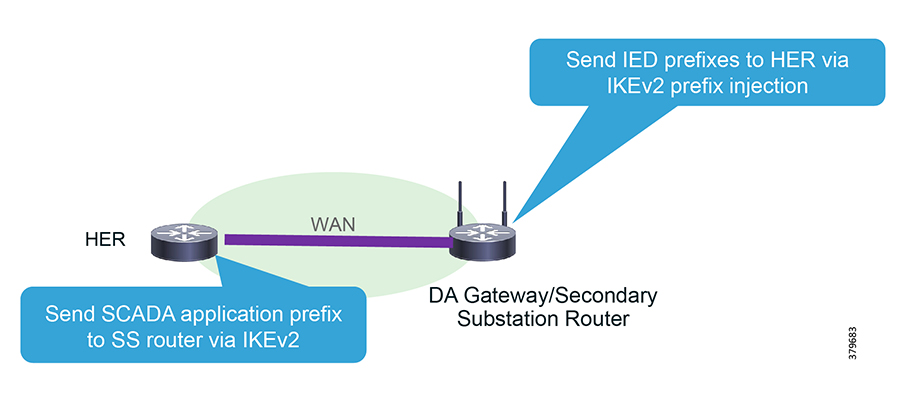
SCADA Services
In order to ensure the proper functioning of substations and related equipment such as line-mounted switches and capacitors, most utilities use SCADA systems to automate monitoring and control.
New sites typically implement a SCADA system to monitor and control substations and related equipment. However, older facilities can also benefit by adding a SCADA system or by upgrading an existing SCADA system to take advantage of newer technologies.
A new or upgraded SCADA system will not only provide better monitoring and control, it can extend the life of substations and related equipment by providing current data for troubleshooting small problems before they escalate. Furthermore, the ample historical data provided by SCADA systems can improve preventive maintenance scheduling and cut associated costs.
SCADA Service Models
Three SCADA Service Models will be supported within this release, as shown in Table 17:
Figure 35 depicts multiple technologies for transporting SCADA traffic. Raw Sockets and Protocol Translation are discussed in detail starting in Raw Sockets. Regular IP routing design will take care of transporting IEC 60870-5-14, DNP3 IP, and Modbus application traffic between IEDs in Secondary Substations and feeders to the SCADA application in the DSO Control Center.
Figure 35 SCADA Use Case Distribution Automation

SCADA Components and Protocols
Monitoring and controlling electrical distribution systems, which involve many remote applications and sites, has often been difficult. To solve this problem, utilities began installing remote terminal/telemetry units (RTUs) at substations. IEDs are a more recent technology development, and these devices are now installed at most substations to some extent.
Remote Terminal Units
An RTU provides intelligent I/O collection and processing such as reading inputs from switches, sensors, and transmitters, and then arranging the representative data into a format that the SCADA system can understand. The RTU also converts output values provided by the SCADA system from their digital form into that which can be understood by field-controllable devices such as discrete (relay) and analog outputs (current or voltage).
Intelligent Electronic Devices
IEDs, which are now installed at most substations to some extent, generally communicate with the substation RTU.
Control Center
The SCADA system consists of a master control station with one or more PC-based human machine interfaces (HMIs). The SCADA system may also contain other secondary control stations with HMIs, and large substations may also have local HMIs.
Operators view information on the HMIs to monitor and control substation operations and related equipment. Modern SCADA systems are extremely adept at handling the large amounts of data necessary to monitor the electrical state of all power lines, cables, and equipment.
SCADA Protocols
Legacy SCADA protocols, which are supported over legacy asynchronous interfaces, include:
Newer SCADA protocols can be transported over Ethernet interfaces:
Many other SCADA protocols exist, but in the utility space only those listed above are discussed.
Raw Sockets
Raw sockets are a means for transporting streams of characters from one serial asynchronous interface to another over the IP network for utility application. Serial communications have been the mainstay for utilities communications for more than a decade using RS232 and RS485 as the physical layer. The industry is currently starting to migrate to Ethernet. However, retrofitting Ethernet and newer IEDs into existing communications systems requires supporting a hybrid network of both Ethernet and serial devices. Raw sockets transport SCADA data from RTUs, support point-to-point and point-to-multipoint connections over an asynchronous serial line, and have a built-in auto Transmission Control Protocol (TCP) connection retry mechanism. Packetization of serial packets that will be triggered will be based on specific packet length or special character or timer. Sub-options are available with the raw rockets feature. The end user can choose these options according to their deployment needs. Monitoring and control (SCADA) data will be routed from the substation to the control center. SCADA communications have latencies ranging from ~500 milliseconds to ~5 seconds.
Raw Socket TCP Transport
TCP raw socket transport uses a client-server model. At most, one server and multiple clients can be configured on a single asynchronous serial line. A raw socket client receives streams of serial data from the RTUs and accumulates this data in its buffer, then places the data into packets, based on user-specified packetization criteria. The raw socket client initiates a TCP connection with the raw socket server and sends the packetized data across the IP network to the raw socket server, which retrieves the serial data from the packets and sends it to the serial interface, and onto the utility management.
Figure 36 depicts three different deployment scenarios for point-to-point raw socket service:
Figure 36 Raw Socket TCP Transport

■![]() Scenario A—Raw socket between SSRs/DA Gateways and SCADA Router in headend; no change on SCADA server; communications through COM ports.
Scenario A—Raw socket between SSRs/DA Gateways and SCADA Router in headend; no change on SCADA server; communications through COM ports.
■![]() Scenario B—Raw socket between IR1101 and SCADA Server; no SCADA application change on server but IP/Serial Redirector software maps COM port to IPv4 address +TCP port, running over the Ethernet interface.
Scenario B—Raw socket between IR1101 and SCADA Server; no SCADA application change on server but IP/Serial Redirector software maps COM port to IPv4 address +TCP port, running over the Ethernet interface.
■![]() Scenario C—Raw socket between IR1101 and SCADA Server; SCADA application knows how to directly communicate over a raw socket (IPv4 address + TCP port) & Ethernet interface.
Scenario C—Raw socket between IR1101 and SCADA Server; SCADA application knows how to directly communicate over a raw socket (IPv4 address + TCP port) & Ethernet interface.
Note: Scenario A is not scalable. Scenario B or Scenario C are highly recommended for raw socket deployments.
Raw Socket UDP Transport
User Datagram Protocol (UDP) transport uses a peer-to-peer model. Multiple UDP connections can be configured on an asynchronous serial line. The raw socket UDP peer receives streams of serial data from the RTUs and accumulates this data in its buffer, and then places the data into packets based on user-specified packetization criteria. Raw socket UDP peer sends the packetized data across the IP network to the raw socket peer at the other end, which retrieves the serial data from the packets and sends it to the serial interface, and on to the utility management system.
Raw Socket Dual Control Center Multi-Drop Bridging
A Raw Socket on the DA Gateway or SSR can replicate its packets to different Control Centers. In Figure 37, two geographically-separated (primary and secondary) DSO Control Centers can be observed, each of them hosting SCADA applications. DA Gateways are configured as a TCP raw socket client with two different sockets, one per control center.
Figure 37 SCADA Multi-Drop Poll

IP routing is key for successful establishment of sockets across the control center. This design serves as a key for disaster recovery and application-level redundancy. The SCADA server in the control center polls RTU periodically. The poll will be addressed to a specific RTU. The HER is configured for replicating application traffic to Raw Socket destinations.
Only the RTU that is addressed by SCADA application replies to poll. The SCADA reply is replicated to all SCADA destinations.
The SCADA reply from the RTU must not be fragmented. The SCADA reply is depicted in Figure 38. In order to prevent fragmentation of the SCADA reply at the TCP layer, the client supports configuration options such as special-char, packet-length, and packet-timer to ensure that the reply is packed correctly into a single TCP packet.
Figure 38 SCADA Multi-Drop Response

From the control center, both simultaneous SCADA application poll and device control operations will be performed. If an RTU wants to send unsolicited reporting, Raw Sockets will replicate application traffic across two different Control Centers.
Protocol Translation
As the utility industry begins the transition from legacy-based SCADA protocols to IP-based protocols, a migration strategy is needed in order to enable both legacy and newer IP-based protocols to interoperate. The protocol translation (otherwise known as the SCADA Gateway feature on the IR1101, IR807, and CGR 1120) provides this capability.
The Cisco IOS SCADA protocol translation function allows translations between:
■![]() IEC-60870-5-101 and IEC-60870-5-104
IEC-60870-5-101 and IEC-60870-5-104
More protocol translation capability could be added with the help of IOx applications leveraging the Edge Compute capability of the platform. For more details, please refer to Cisco IoT Connected Utilities Virtual RTU Implementation Guide, at the following URL:
■![]() https://www.cisco.com/c/en/us/td/docs/solutions/Verticals/Utilities/FAN/Virtual-RTU/IG/CU-VRTU-IG.html
https://www.cisco.com/c/en/us/td/docs/solutions/Verticals/Utilities/FAN/Virtual-RTU/IG/CU-VRTU-IG.html
The following software stacks are implemented in the Cisco SSRs or DA Gateways:
■![]() IEC-101 and DNP3 serial Protocol Stack
IEC-101 and DNP3 serial Protocol Stack
■![]() IEC-104 and DNP3 IP Protocol Stack
IEC-104 and DNP3 IP Protocol Stack
■![]() Translation Module to translate between:
Translation Module to translate between:
In Figure 39, IR1101 IR1101 can be observed as deployed as a SCADA Gateway. SCADA Gateway will host both T101 Master and T104 Slave functionalities. One RTU per serial interface will be connected. The DA Gateway/SSR will act as the T101 Master for the T101 Slave RTU. In turn, the DA Gateway/SSR will acts as the T104 Slave to the SCADA T104 Master residing in the control center. This scenario depicts the point-to-point protocol translation scenario.
Figure 39 Raw Sockets Point to Point
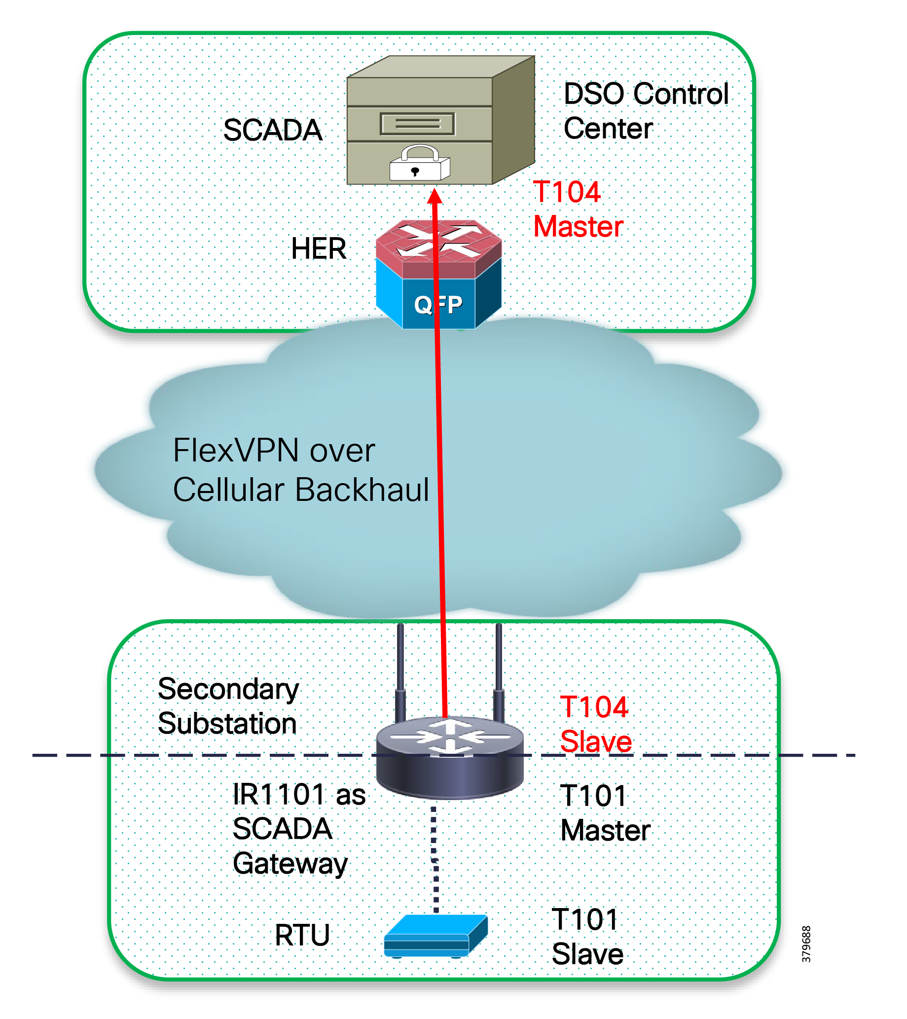
T101/T104 Protocol translation features:
■![]() T101/T104 refers to the IEC 60870-5-101 and IEC 60870-5-104 standard, respectively.
T101/T104 refers to the IEC 60870-5-101 and IEC 60870-5-104 standard, respectively.
■![]() T101 supports the point-to-point and multi-drop links over serial communications.
T101 supports the point-to-point and multi-drop links over serial communications.
■![]() T104 uses TCP/IP transport and network protocols to carry the application data (ASDU), which was specified in T101.
T104 uses TCP/IP transport and network protocols to carry the application data (ASDU), which was specified in T101.
■![]() Allows balanced and unbalanced communication types:
Allows balanced and unbalanced communication types:
–![]() Balanced mode is limited to point-to-point links where either station can initiate transaction (similar to DNP3 unsolicited response).
Balanced mode is limited to point-to-point links where either station can initiate transaction (similar to DNP3 unsolicited response).
–![]() Unbalanced mode is suitable for multi-drop links where only the master station can send primary frames.
Unbalanced mode is suitable for multi-drop links where only the master station can send primary frames.
DNP3/ DNP3 IP Protocol translations features:
–![]() Poll all data from RTU every 90 seconds.
Poll all data from RTU every 90 seconds.
–![]() Provide local time to RTU every 90 seconds.
Provide local time to RTU every 90 seconds.
–![]() Support file transfer to and from RTU.
Support file transfer to and from RTU.
–![]() Enable/disable of unsolicited response on RTU.
Enable/disable of unsolicited response on RTU.
–![]() Respond to control center request with local data.
Respond to control center request with local data.
–![]() Trigger counter interrogation to RTU when receive such request from control center.
Trigger counter interrogation to RTU when receive such request from control center.
–![]() Trigger control transaction to RTU when received such request from the control center.
Trigger control transaction to RTU when received such request from the control center.
–![]() Support file transfer to and from control center.
Support file transfer to and from control center.
–![]() Enable/disable of sending unsolicited response to control center.
Enable/disable of sending unsolicited response to control center.
Figure 40 depicts multi-master scenario protocol translation scenario where the SCADA Gateway router establishes two different TCP connections with the SCADA master in the primary and secondary control center. Both SCADA masters will be able to do the poll and control of RTU. If RTU needs to send an unsolicited report, SCADA Gateway will replicate the report to both SCADA masters.
Figure 40 Protocol Translation Multi-Master Scenario

Network Address Translation
The IoT Gateway has the capability to support the NAT as well as Port Address Translation (PAT). Figure 41 captures a couple of deployment scenarios, one involving NAT-PAT and the second scenario without any NAT-PAT:
Figure 41 IoT Gateway's NAT Capabilities vs non-NAT Capabilities

SCADA communicates with IED’s IP on application port number. For example, in Figure 41, the SCADA communication is sent to 10.16.21.2 port 2404 directly (yellow line). |
SCADA communicates with IoT Gateway's Loopback IP address and on Application/Custom port number. IoT Gateway translates the communication and is sent to the IED on Application/Custom port number. For example, in Figure 41, the SCADA communication is sent to Loopback IP of Gateway (192.168.150.21) on port 2404, which, after reaching the IoT Gateway, consultation is made with the NAT Table, is translated to 192.168.0.2 port 2404, and then sent to IED. |
All ports of that IED's IP address are open for communication. This could be a possible security risk. |
Only desired application ports are opened up at the IoT Gateway for communication with IED. This adds up to the security of the IED. For example, when the IED is supposed to receive T104 traffic, the IoT Gateway could be remotely provisioned (from FND) to open up the default port 2404 of T104 (or) any custom port as utility customer desires. |
Each and every IED must be configured with utility scope routable IP address, along with configuring on the IoT Gateway's interface. This method might consume twice the utility scope routable IP address for each IED. Configuring hundreds of thousands of IEDs could be a huge overhead, especially for configuring unique Utility scope routable IP address on the IED. |
All IEDs can be configured with the same IP address (for example, 192.168.0.2). The overhead in configuring hundreds of thousands of IEDs with unique and correct utility scope routable IP address has been drastically reduced. To make the IED deployment even easier, the IP address of 192.168.0.2 could be allocated to the IED, if the IED is capable of sending the DHCP request. Provisioning IoT Gateway is made easy and remotely doable with the power of FND: ■ ■ |
Every IoT Gateway has to advertise the IP address of the IED, in addition to advertising its loopback address. |
The IoT Gateway need not advertise the IP address of the IED and only advertises its loopback address, which uniquely represents the IoT Gateway. |
IEDs to be allocated with routable addresses within the utility network scope, which could be an overhead for scaled number of deployments. |
No overhead associated, as IED IP is not advertised. Very much scalable as it's almost like PNP for IED, if IED is configured for DHCP. |
Network reachability information of each of the IEDs connected to their respective IoT Gateways has to be available in the HER's routing table, thus consuming more memory space. More resource consumption would have its impact on scalability of HER. |
IED can be reached over IoT Gateway's loopback address itself. Network reachability information of IED is masked by the IoT Gateway. Frees up lots of memory resource on the HER, which could enhance the scaling on HER. |
Migration from one subnet to another subnet requires IED to be reconfigured. |
No reconfiguration required on IED. Any configuration changes could be handled at the IoT Gateway layer itself with the help of FND. |
Since the IP address of the IED itself is advertised, all the port numbers on the IED are exposed to communication requests/denial of service attacks. |
This is a security advantage. Only the application ports that the IED serves (for example, port 2404 while serving IEC 60870-5-104) are opened up at the IoT Gateway. Any communication attempt on another port number will be cut off at the IoT Gateway itself. This certainly frees up lots of CPU cycles of IED, allowing IED to process one and only Interesting traffic. |
Once the IED is configured to listen on certain port number (for example, 2404) and deployed on the field, if the SCADA server wants to establish communication on a custom port number other than 2404, a reconfiguration is needed on IED. |
Since the IED is network and port translated at the IoT Gateway, the SCADA could communicate with the IoT Gateway on any custom port number, and the IoT Gateway could translate the communication to 192.168.0.2 on port 2404 (for which the IED is configured to receive). |
Since the IP address of the IED is exposed, there is a prevailing risk of attacks on IED. Could be mitigated with ACLs on the cellular interface. Thus, permitting the communication to IED only from the DSO headend through the Flex-VPN Tunnel. |
With only the secure Flex-VPN Tunnel interface configured to receive NAT inbound traffic from the DSO headend (read: 'ip nat outside' enabled on Tunnel interface), the only way to establish a communication with the IED is incoming through the secure tunnel from the DSO Control Center. Incoming traffic on any interface other than secure tunnel interface would get dropped, as the translation works only for NAT (outside) enabled ports (which is tunnel interface only). As the 'ip nat outside' is not enabled on the cellular interface, even if there is an attack on cellular interface on port 2404, the attack would be dropped by the IoT Gateway itself. The attack never reaches the IED. While at the same time, the IED would be smoothly communicating with the SCADA headend on port 2404. This case, the attack is canceled by the IoT Gateway. No one on the Internet would be able to NAT/PAT connect to IED, unless they come through the secure tunnel from the DSO headend. |
IP address of the IED is reachable to DSO headend only after secure FlexVPN tunnel is established. |
IP address of the IED is not exposed. Only the IP address of the loopback interface is exposed, which is reachable to DSO headend only after secure FlexVPN tunnel is established. SCADA could reach the IED via the IoT Gateway's loopback address, on application port numbers (port number 20000 for DNP3, 2404 for IEC 60870-5-104, or any custom port), as per the configuration provisioned remotely from Cisco IoT FND. Additional ports could be opened up on IoT Gateway for IED at any point in time, as the IoT Gateway could be remotely re-provisioned from FND, whenever needed. |
Would be slightly slow (relative to not having NAT), as NAT consumes extra CPU cycles on the IoT Gateway. However, the IoT Gateway is powerful enough to handle this with ease. |
|
End-to-end communication is not permitted by design. Only the needed application ports are opened up. |
|
Ping test from SCADA is responded by the IoT Gateway, as the communication point is the Loopback IP of the IoT Gateway, not IED. |
While Table 18 summarizes the advantages of NAT/PAT, if the customer intends to deploy a non-NAT scenario, that too could be secured with ACLs on the cellular port, denying the access to the IED IP. At the same time, the SCADA communication from the DSO headend to IED could be honored, as it arrives over the encrypted tunnel, and therefore should be able to reach the IED.
Note: Use of the NAT scenario is recommended; this can help in easy deployment and scalability unless the end-to-end traceability requirement is mandatory.
Quality of Service
Quality of Service (QoS) and Class of Services (CoS) refer to the ability of the network to provide priority service to selected network traffic. Improved and more predictable network service can be offered by:
■![]() Supporting dedicated bandwidth—that is, cellular links have different upload/download bandwidth/throughput
Supporting dedicated bandwidth—that is, cellular links have different upload/download bandwidth/throughput
■![]() Reducing loss characteristics—DA real-time traffic prioritization
Reducing loss characteristics—DA real-time traffic prioritization
■![]() Avoiding and managing network congestion—multi-services traffic
Avoiding and managing network congestion—multi-services traffic
■![]() Setting traffic priorities across the network—multi-services capabilities
Setting traffic priorities across the network—multi-services capabilities
QoS is a key feature when designing a multi-services Distribution Automation solution since differentiation and prioritization must occur between traffic from AMI, Distribution Automation, Remote Workforce, and network management use cases. Estimated transport losses, delay, and jitter introduced by networking devices must be understood when forwarding sensitive data particularly when a WAN backhaul link offers a limited amount of bandwidth.
In the case of dual-WAN interfaces with different bandwidth capabilities (that is, cellular), QoS policies must be applied to prioritize the traffic allowed to flow over these limited bandwidth links, to determine which traffic can be dropped, etc.
On a multi-services DA solution, QoS DiffServ and CoS (IEEE 802.1p) can apply to traffic categorized as:
■![]() IPv4 Traffic—Distribution Automation (FLISR), protocol translation (RTU monitoring), and network management
IPv4 Traffic—Distribution Automation (FLISR), protocol translation (RTU monitoring), and network management
■![]() IPv6 Traffic—IPV6 IED AMI and network management
IPv6 Traffic—IPV6 IED AMI and network management
■![]() Layer 2 Traffic—Distribution Automation such as IEC 61850 GOOSE/SV traffic switches between Ethernet interfaces, IEC 61850 traffic bridged over WAN links between substations
Layer 2 Traffic—Distribution Automation such as IEC 61850 GOOSE/SV traffic switches between Ethernet interfaces, IEC 61850 traffic bridged over WAN links between substations
Figure 42 lists different priorities among Distribution Automation traffic. IP-based protocols can be classified using DSCP. Ethernet Layer 2-based protocols like GOOSE could be classified using CoS.
Figure 42 DA Traffic Priority Chart

Following the IETF DiffServ model, the Distribution Automation solution will deliver a particular kind of service based on the QoS specified by each packet. This specification can occur in different ways, for example, using the IP Precedence bit settings in IP packets or source and destination addresses. QoS specification can be used to classify, mark, shape, and police traffic, and to perform intelligent queuing.
The SSR or DA Gateway perform QoS actions on Layer 3 (cellular, Ethernet) interfaces. The sequencing of QoS actions on egress traffic is as follows:
Upstream QoS: From Distribution Automation IED to SCADA
DA IEDs perform the marking functionality. If IED does not have the capability to mark the IP packets, the DA Gateway or SSR can perform the marking functionality. On egress WAN interface, queuing will be performed. High priority FLISR and GOOSE traffic will be assigned in Low Latency Queue. Medium priority traffic like Volt/VAR and Manufacturing Message Specification (MMS) will be assigned in Class-Based Weighted Fair Queue 1 and IoT FND Network Management traffic will be assigned in Class-Based Weighted Fair Queue2. The rest of the traffic will be treated with normal priority and will be assigned to the default queue. All QoS is done based on DSCP marking.
Note: It is recommended to define queuing bandwidth as remaining percentage instead of values so that the same policy can be applied across Cellular or Ethernet backhaul interfaces.
If RTU is connected to DA Gateway via R232 async serial interface and, if the raw socket feature is enabled, marking will be enabled on the serial line.
HER-ASR 1000 supports the rich QoS feature set from Cisco IOS. For further details, please refer to Cisco ASR 1000 Series Aggregation Services Routers: QoS Architecture and Solutions at the following URL:
■![]() https://www.cisco.com/c/en/us/products/collateral/routers/asr-1002-router/solution_overview_c22-449961.html
https://www.cisco.com/c/en/us/products/collateral/routers/asr-1002-router/solution_overview_c22-449961.html
The ASR 1000 provides DoS protection for applications like FND and SCADA.
Figure 43 Upstream QoS: IED to SCADA

Downstream QoS: From SCADA to IED
Applications like SCADA and FND generate DSCP markings based on message priority. The HER ASR 1000 provides egress shaping/policing based on DSCP marking. This achieve DoS protection and traffic prioritization. The DA Gateway queues the packets based on DSCP Marking.
Figure 44 Downstream QoS: From SCADA to IED

Note: QoS behavior is always on a per-hop basis. Even though the high priority traffic is prioritized at the IoT Gateway, once the traffic enters the service provider's network, the packets are subjected to the QoS treatment as defined by the service provider. In some scenarios, the service provider could even remark all the incoming packet's priority to default priority. It is recommended to ensure a SLA if the QoS marking done at the gateway needs to be honored by the service provider (or) at least treated as per the SLA.
Timing Synchronization
The DA Secondary Substation solution supports a multiple arrays of applications. Many of these applications process a time-ordered sequence of events; therefore, the events must be time stamped to a level of precision where individual events can be distinguished from one another and correctly ordered. Timing synchronization can be achieved by using various protocols that depend upon time accuracy and the time sources. Table 19 shows the time accuracy that might be required by different DA use cases:
Isolation and restoration, assuming protection action happening locally |
||
The time synchronization mechanisms available for DA solution include:
■![]() NTP—The NTP delivers accuracies of 10 to 100ms, depending upon the characteristics of synchronization sources and network paths. NTP version 4 is used and the NTP server is placed in the control center. The DA Gateways and the SSR act as a NTP client.
NTP—The NTP delivers accuracies of 10 to 100ms, depending upon the characteristics of synchronization sources and network paths. NTP version 4 is used and the NTP server is placed in the control center. The DA Gateways and the SSR act as a NTP client.
■![]() GPS—In the Cisco IR 800 series platform, GPS can be configured as a clock source (Cisco IOS software release 15.8.3M0a onwards).
GPS—In the Cisco IR 800 series platform, GPS can be configured as a clock source (Cisco IOS software release 15.8.3M0a onwards).
DHCP Services
Staging Phase of ZTD
One of the four PnP server discovery mechanisms (DHCP server-assisted PnP Provisioning) uses the DHCP server to derive the PnP server details. As part of staging, while the DHCP server advertises the IP address to the IoT Gateway. PnP server details are also advertised as part of Vendor Specific Options.
For more details on this DHCP server usage, please refer to the following URL:
■![]() https://www.cisco.com/c/en/us/td/docs/ios-xml/ios/pnp/configuration/xe-3e/pnp-xe-3e-book.html#concept_D734333B30304AB780BBDB5487DA73D3
https://www.cisco.com/c/en/us/td/docs/ios-xml/ios/pnp/configuration/xe-3e/pnp-xe-3e-book.html#concept_D734333B30304AB780BBDB5487DA73D3
Tunnel Provisioning Phase of ZTD
During the tunnel provisioning phase of the ZTD, Cisco IoT FND sends out a DHCP relay request for IPv4 and IPv6 addresses on behalf of the IoT Gateway attempting ZTD. The DHCP server should be configured to allocate an IPv4 and IPv6 address for the gateway. Once Cisco IoT FND receives the IPv4 and IPv6 addresses from the DHCP server, Cisco IoT FND compiles the tunnel provisioning configuration and pushes it onto the IoT Gateway with the help of intermediate TPS. The IPv4 and IPv6 addresses configured on the IoT Gateway help Cisco IoT FND and SCADA application to uniquely identify the IoT Gateway.
Zero Touch Onboarding of Cisco IOS Routers
This chapter includes the following major topics:
■![]() Cisco Network PnP—Available Discovery Methods
Cisco Network PnP—Available Discovery Methods
■![]() Bootstrapping and Deployment Options
Bootstrapping and Deployment Options
■![]() Actors Involved in PnP and Their Roles
Actors Involved in PnP and Their Roles
Zero Touch onboarding is done with the help of the Network Management System (NMS), which resides as part of the communication headend. The NMS of this solution is referred to as the Field Network Director (FND), which is a software platform that manages the multi-service network and security infrastructure for IoT applications in this Distribution Automation solution. The IoT FND also incorporates the PnP server component, to serve the purpose of bootstrapping using PnP protocol.
Note: This document considers the option of Zero Touch Onboarding using the Cisco IoT FND as the Network Management platform as well as the PnP server.
About Zero Touch Deployment
Zero Touch Deployment (ZTD) is a powerful process available for onboarding hundreds of thousands of the Secondary Substation Routers (SSRs) and DA Gateways onto the network. These devices can be deployed on the field and be brought to a fully operational state with no manual intervention. Throughout this section, Cisco IOS routers (including SSRs or DA Gateways) are referred as the Cisco IoT Gateway.
Note: The field technician only has to mount the devices in the desired location and power it up. The remainder is left to the ZTD process. The flexibility offered by ZTD is a much-needed capability, particularly during scaled deployments. ZTD helps to decrease the Total Cost of Ownership (TCO) of the deployment.
Considering that on-premise FND is used as the network management platform in this solution, ZTD happens in two stages:
Staging of the Cisco IoT Gateway
Cisco IoT Gateway, by default, comes with factory default configuration. However, certain minimal configuration (referred as express-configuration or day0 configuration) is needed in order for ZTD to kick in. The process of adding this minimal configuration to the IoT gateway is referred as to as “Staging.” This could be a manual procedure (or) an automated procedure with the help of Plug 'n Play provisioning.
As part of staging, the IoT Gateway can be provisioned with the express-configuration using a dynamic procedure, by leveraging the PnP architecture. This dynamic procedure can be referred to as PnP bootstrapping.
Deployment of the Cisco IoT Gateway
Once deployed in the desired location, the bootstrapped Cisco IoT Gateway goes through the following procedure:
■![]() Receives its WAN IP address dynamically from the provider (can be over Ethernet or Cellular)
Receives its WAN IP address dynamically from the provider (can be over Ethernet or Cellular)
■![]() Receives the Utility PKI-signed certificate dynamically through SCEP
Receives the Utility PKI-signed certificate dynamically through SCEP
■![]() Gets a secure tunnel provisioned to the DSO headend by contacting TPS
Gets a secure tunnel provisioned to the DSO headend by contacting TPS
■![]() Receives the “Application traffic enabling” configuration and other device configurations while registering with FND
Receives the “Application traffic enabling” configuration and other device configurations while registering with FND
■![]() Keeps Cisco IoT FND updated about its status through periodic updates
Keeps Cisco IoT FND updated about its status through periodic updates
Figure 45 Zero Touch Deployment—Blocks

For a high-level overview of the ZTD, please refer to the following URL:
■![]() https://www.cisco.com/c/en/us/td/docs/routers/connectedgrid/iot_fnd/guide/4_2/iot_fnd_ug4_2/overview.html#47 969
https://www.cisco.com/c/en/us/td/docs/routers/connectedgrid/iot_fnd/guide/4_2/iot_fnd_ug4_2/overview.html#47 969
For more detailed interactions between various components involved in ZTD, please refer to the Cisco FAN - Headend Deep Dive Implementation and FAN Use Cases at the following URL:
■![]() https://salesconnect.cisco.com/#/content-detail/da249429-ec79-49fc-9471-0ec859e83872
https://salesconnect.cisco.com/#/content-detail/da249429-ec79-49fc-9471-0ec859e83872
Note: The remainder of this section focuses on the bootstrapping of Cisco IOS routers using the Cisco Network PnP server, which is hosted on the Cisco IoT FND, the NMS of the Cisco FAN solution.
What is Cisco Network PnP?
Cisco Network Plug 'n Play (PnP) is a secure and scalable solution for simple Day-Zero provisioning of Cisco IoT gateways such as IR1101, CGR1120, CGR1240, IR807, IR809, or IR829. The PnP server application runs on top of Cisco IoT FND.
Cisco Network PnP—What It Is
It is a Cisco IoT FND add-on component (PnP server) that helps in bootstrapping the Cisco routers with the minimal configuration required to kick start the ZTD procedure.
Cisco Network PnP—What It Is Not
It is a NOT a substitute for the ZTD procedure. Instead, PnP bootstrapping complements the ZTD procedure by automating the procedure that helps loading the express-configuration onto the routers.
Cisco Network PnP—What Problem Does It Solve
Because Cisco network PnP is an automated procedure:
■![]() Any manual steps (in turn, any human error) for staging are eliminated.
Any manual steps (in turn, any human error) for staging are eliminated.
■![]() Templated configuration ensures consistency in express-configuration.
Templated configuration ensures consistency in express-configuration.
Cisco Network PnP—Major Actors
Major actors involved in the Cisco network PnP are:
For more details about the actors involved, please refer to Actors Involved in PnP and Their Roles.
Cisco Network PnP—Available Discovery Methods
■![]() In the absence of the Cisco IoT Gateway startup being configured, the PnP server discovery kicks in.
In the absence of the Cisco IoT Gateway startup being configured, the PnP server discovery kicks in.
■![]() When PnP server discovery is in progress, any key press on the Cisco IoT Gateway console could terminate the PnP server discovery procedure since it's a manual intervention on the router.
When PnP server discovery is in progress, any key press on the Cisco IoT Gateway console could terminate the PnP server discovery procedure since it's a manual intervention on the router.
■![]() Both cost saving and time saving are achieved, since staging is dynamically addressed.
Both cost saving and time saving are achieved, since staging is dynamically addressed.
Four Methods for PnP Server Discovery
The IoT Gateway discovers the FQDN or IP address of PnP server with any of the four different methods:
■![]() PnP server discovery through DHCP server
PnP server discovery through DHCP server
■![]() PnP server discovery through DNS server
PnP server discovery through DNS server
■![]() PnP server discovery through Cisco PnP Connect (aka Cloud Redirection Service)
PnP server discovery through Cisco PnP Connect (aka Cloud Redirection Service)
■![]() PnP server defined via Manual PnP profile.
PnP server defined via Manual PnP profile.
The bootstrapping location and the chosen network type (LTE/Ethernet) will dictate the choice of the PnP server discovery method.
When the Cisco IoT gateway boots up without startup configuration, the PnP agent that comes integrated into the latest releases of the Cisco IOS software kick-starts the PnP server discovery process. This happens automatically with no manual intervention on the router.
■![]() In environments using TPS as PnP Proxy, PnP Proxy IP/FQDN must be advertised in place of the PnP server IP/FQDN.
In environments using TPS as PnP Proxy, PnP Proxy IP/FQDN must be advertised in place of the PnP server IP/FQDN.
■![]() After discovery of PnP server using DHCP, DNS, or Cloud redirection services, a PnP server profile is dynamically created on the IoT Gateway.
After discovery of PnP server using DHCP, DNS, or Cloud redirection services, a PnP server profile is dynamically created on the IoT Gateway.
Figure 46 PnP Server Discovery Flow
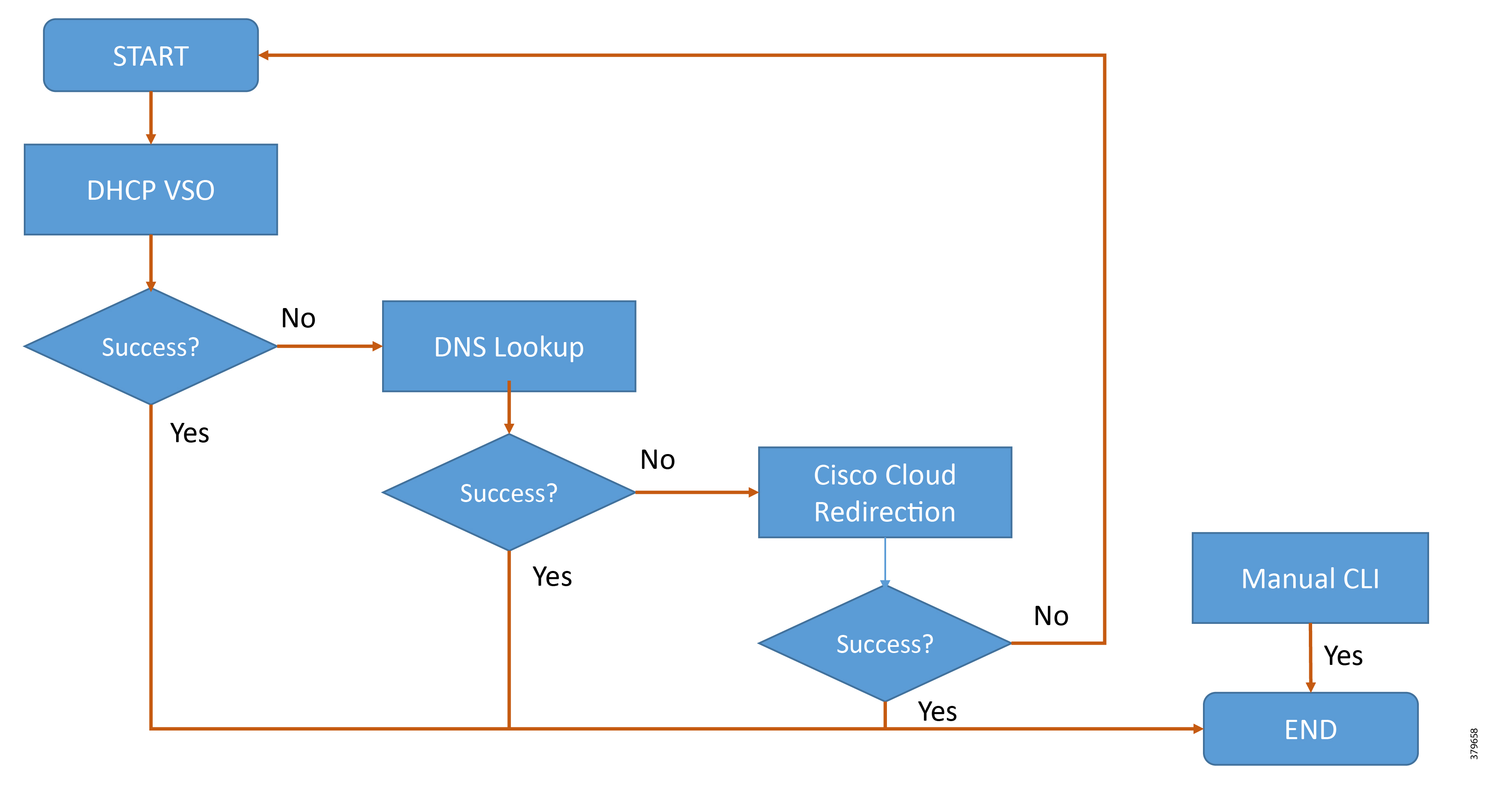
■![]() In environments using TPS as PnP Proxy, PnP Proxy IP/FQDN must be advertised in place of the PnP server IP/FQDN.
In environments using TPS as PnP Proxy, PnP Proxy IP/FQDN must be advertised in place of the PnP server IP/FQDN.
■![]() After discovery of PnP server using DHCP, DNS, or Cloud redirection services, a PnP server profile is dynamically created on the IoT Gateway.
After discovery of PnP server using DHCP, DNS, or Cloud redirection services, a PnP server profile is dynamically created on the IoT Gateway.
PnP Server Discovery Through DHCP Server
This is a dynamic discovery method to learn the PnP server detail. The PnP agent on the Cisco router first attempts the DHCP server-assisted provisioning; if that succeeds, the PnP discovery should complete and the router should reach out to the discovered PnP server for bootstrapping. The IP/FQDN address of the PnP server is obtained through vendor-specific options from the DHCP server:
■![]() Vendor Specific Option 43 is used to advertise PnP proxy/server in the IPv4 network.
Vendor Specific Option 43 is used to advertise PnP proxy/server in the IPv4 network.
■![]() Vendor Specific Option 9 is used to advertise PnP proxy/server over the IPv6 network.
Vendor Specific Option 9 is used to advertise PnP proxy/server over the IPv6 network.
■![]() The PnP agent in Cisco IoT gateway sends out a case-sensitive “ciscopnp” as the option 60 string during the DHCP discovery.
The PnP agent in Cisco IoT gateway sends out a case-sensitive “ciscopnp” as the option 60 string during the DHCP discovery.
■![]() The DHCP-based discovery happens over the Layer 3 WAN port. In cases where the WAN port is the Layer 2 switch port, the corresponding Layer 3 SVI interface could be used for DHCP.
The DHCP-based discovery happens over the Layer 3 WAN port. In cases where the WAN port is the Layer 2 switch port, the corresponding Layer 3 SVI interface could be used for DHCP.
The DHCP server could be configured with multiple classes matching to a different option 60 string that comes from each network device. After the option 60 string matches, the DHCP server sends out the corresponding vendor-specific option string back to the device.
Either the utility must have control over the DHCP server (or) an agreement must be established with the Service Provider to match on (case-sensitive ciscopnp as the) option 60 string in the DHCP discover message, and provide back the required vendor-specific option (43 for IPv4, 9 for IPv6) to the Cisco IoT gateways.
In Figure 47, the PnP-capable Cisco IoT gateway sends out a DHCP request, following which the PnP server details are advertised using DHCP option 43 by the DHCP server. This results in the dynamic creation of the PnP bootstrapping profile on the Cisco IoT gateway. As the server detail includes an FQDN, the gateway performs a name resolution and sends out the bootstrapping request to the PnP proxy. As a result, the express-configuration is pushed onto the Cisco IoT gateway.
Figure 47 PnP Server FQDN Discovery through DHCP Server over IPv4 Network

In Figure 48, PnP-capable Cisco IoT gateway sends out a DHCP request, following which the PnP server details are advertised using DHCP option 9 (for IPv6) by the DHCP server. This results in dynamic creation of a PnP bootstrapping profile on the Cisco IoT gateway followed by bootstrapping.
Figure 48 PnP Server FQDN Discovery Through DHCP Server over IPv6 Network

In Figure 49, the DHCP server advertises the IPv4/IPv6 address (instead of FQDN) under vendor-specific option 43/option 9. The DHCP response, once received by the Cisco IoT gateway, results in dynamic creation of the PnP bootstrapping profile. Bootstrapping request would be sent to the advertised PnP proxy IP address on port 9125.
Figure 49 PnP Server IP Discovery Through DHCP Server VSO

PnP Server Discovery Through DNS Server
This is a dynamic discovery method to learn the PnP server detail. If the PnP server detail (as Vendor Specific Option) is not found in the DHCP response, then the DNS server-assisted provisioning will be attempted next. Assuming the domain name advertised in the DHCP response is domain.com, the IP address of the PnP server could be obtained through the DNS name resolution of pnpserver.domain.com.
To enable this name resolution to happen, the DNS server should be configured with:
■![]() An “A record” to deliver IPv4 address of the PnP server/proxy server (and/or)
An “A record” to deliver IPv4 address of the PnP server/proxy server (and/or)
■![]() An “AAAA record” to deliver IPv6 address of the PnP server/proxy server
An “AAAA record” to deliver IPv6 address of the PnP server/proxy server
This way, the PnP agent on the Cisco IoT gateway could discover the PnP server detail using the DNS. If this succeeds, the PnP discovery should be complete, and the router should reach out to the received PnP server IP for bootstrapping.
Note: To use this method, the DNS must be under the control of the utility or an agreement must be established with the IP provider to add the required name resolution entries on their name resolution servers.
In Figure 50, there wasn't any PnP server detail from the DHCP vendor-specific options. Therefore, the Cisco IoT gateway would then send out a name resolution request to pnpserver.domain.com. If the name resolution is successful, a PnP server profile is created dynamically on the Cisco IoT gateway, which would result in bootstrapping of the gateway.
Figure 50 PnP Server Discovery Through DNS Server

PnP Server Discovery Through Cisco PnP Connect
If the PnP server couldn't be discovered through DHCP/DNS server, then the discovery will be attempted using Cisco PnP Connect. This could also be referred to as the Cisco PnP cloud redirection service.
Figure 51 PnP Server Discovery Through Cisco PnP Connect

This is a dynamic discovery method used by the Cisco IoT gateways to learn the PnP server detail. This discovery option requires a smart account on the software.cisco.com portal under the “Network Plug and Play” section (refer to https://software.cisco.com/software/csws/ws/platform/home?locale=en_US&locale=en_US#). The Smart Account could be assigned to the Network Plug and Play-capable IoT gateways while ordering through the CCW (Cisco Commerce Workspace) ( https://apps.cisco.com/Commerce/guest); doing so automatically helps populate the devices in the PnP Connect portal. Alternatively, the network devices (Cisco IoT gateways) could also be added manually to the smart account in the PnP Connect portal.
Note: The controller profile defined on the PnP Connect portal to carry the details of the PnP proxy/server and the Cisco IoT gateway devices need to be mapped to the appropriate controller profile.
When the Cisco IoT gateway reaches out to the Cisco PnP cloud service at devicehelper.cisco.com, the gateway is provided with the IP address/FQDN of the PnP server. This results in the dynamic creation of the PnP server profile on the Cisco IoT gateway.
This way, the PnP agent on the Cisco IoT gateway could discover the PnP server detail using the Cisco PnP Connect. If this succeeds, the PnP discovery should be complete, and the router should then reach out to the received PnP server IP/FQDN for bootstrapping.
Note: This discovery mechanism is more suited for deployments where the DHCP/DNS server aren't under the control of utilities (for example, public Ethernet/LTE networks).
PnP Server Defined via Manual PnP Profile
This is a manual method to let the Cisco IoT gateway know the detail of the PnP server.
Figure 52 PnP Proxy/Server Details Defined Via Manual Profile

While the above three options are completely automated ways of obtaining the IP address of the PnP server, a manual CLI approach also exists. Network administrators may use the CLI configuration mode to initiate the PnP agent process at any time. By configuring a PnP profile through CLI, a network administrator can start and stop the PnP agent on a device. When the PnP profile is configured with CLI, the device starts the PnP agent process which, in turn, initiates a connection with the PnP server using the IP address in the PnP profile.
References for PnP Server Discovery Process
More details about the PnP server discovery process, along with useful graphics, can be found under the “Plug-n-Play Agent Discovery Process” section of the Cisco Open Plug-n-Play Agent Configuration Guide.
Bootstrapping and Deployment Options
Secure ZTD of Cisco IoT gateway can be divided into the multiple phases:
1.![]() Express-configuration provisioning
Express-configuration provisioning
2.![]() Certificate enrollment phase
Certificate enrollment phase
Figure 53 Bootstrapping versus Deployment

The multiple phases defined above could be broadly classified into two categories:
■![]() Bootstrapping (which includes the express-configuration provisioning phase)
Bootstrapping (which includes the express-configuration provisioning phase)
Bootstrapping Location
The location that facilitates bootstrapping of Cisco IoT gateways using PnP is referred to as the bootstrapping location. This could be a dedicated location meant for bootstrapping purposes only, or it could be the same as the deployment location (for selective PnP server discovery methods like Cisco PnP Connect).
In the case of a dedicated bootstrapping location, the Cisco IoT gateways could be unpacked from the box, PnP bootstrapped dynamically at the staging premise, powered off, transported, and deployed at the desired deployment location, and then finally powered on.
Note: Only bootstrapping happens in this location. Deployment happens in a different (deployment) location.
Bootstrapping of Cisco IoT Gateways - Logical Call Flow
When the device boots up for the first time, if no startup configuration occurs on the box, the PnP server discovery procedure would kick start. Using any of the PnP server discovery methods discussed in Four Methods for PnP Server Discovery, the PnP profile is created on the IoT gateway. The dynamically-configured profile could instruct the gateway to connect to PnP proxy over http on port 9125 (or 80), or to connect to PnP proxy over https on port 9120. This depends on the information advertised during the PnP server discovery mechanism.
Figure 54 Bootstrapping of IoT Gateways - Logical Call Flow

The above call flow assumes that the PnP profile is configured to reach the PnP proxy over HTTP on port 9125. As per the call flow, the initial communication would be over HTTP on port 9125. Later, the communication would be switching over to HTTPS (on port 9120) for further bootstrapping. Once the full express-configuration is pushed to the Cisco IoT gateway, the PnP profile is removed from the Cisco IoT gateway and bootstrapping is declared as completed.
Note: With reference to the Cisco Field Area Networks solution, PnP proxy would be positioned in the DMZ space. The TPS serving the role of Tunnel Provisioning Server in ZTD could additionally be configured to serve as PnP proxy.
Deployment Location
The desired location, where the Cisco IoT gateways are meant to be finally deployed, to achieve the desired use case is referred to as “deployment location.”
In some cases, the pre-bootstrapped device is deployed at the deployment location. In other cases, the non-bootstrapped Cisco IoT gateway could be unpacked and deployed directly at the deployment location, altogether skipping the staging premise (in such case, bootstrapping and deployment happens from the deployment location itself).
Two Approaches to Bootstrapping and Deployment
Bootstrapping and deployment could exist at two separate locations or at the same location. This differentiation, which is primarily based on the location from where the device is bootstrapped, is discussed in this section.
Approach 1: IoT Gateway Bootstrapped in Staging Location but Deployed in a Different Location
In this approach, bootstrapping of the IoT Gateways are done at the dedicated staging location. Once the devices are bootstrapped successfully, they are then powered off and transported to the final deployment locations.
More than one staging premise could exist. The PnP proxy/server could either be located locally in the staging premise or could be located in some central premise securely connected over WAN, thus catering to distributed staging premises.
In Figure 55, the local staging premise hosts PnP Proxy/Server locally within the premise. This could be an entirely private connection and Internet connection may not be needed.
On the left, “N” number of distributed staging premises are connected to the centrally-hosted PnP Proxy over a WAN network. The common bootstrap template could be maintained at one central PnP server, with many distributed sites catering to the staging of the IoT Gateway.
Figure 55 Bootstrapping of IoT Gateway at the Staging Premises (Local vs Distributed)

■![]() Bootstrapping could be done over IPv4 Network or IPv6 Network.
Bootstrapping could be done over IPv4 Network or IPv6 Network.
■![]() IR1101 also supports bootstrapping over Native IPv6 Network.
IR1101 also supports bootstrapping over Native IPv6 Network.
Figure 56 Deployment of IoT Gateway at the Desired Location, with Remainder of ZTD over Cellular/Ethernet

As shown in Figure 56, staged IoT Gateways are deployed on the Secondary Substation and the Distribution Network and are powered up. The pre-bootstrapped IoT Gateways activate the ZTD procedure and then proceeds with:
1.![]() Certificate enrollment to receive the certificate for the Gateway from the Utility PKI.
Certificate enrollment to receive the certificate for the Gateway from the Utility PKI.
2.![]() Provisioning a secure communication with the DSO Control Center.
Provisioning a secure communication with the DSO Control Center.
3.![]() Establishing a secure communication path between IoT Gateway and the DSO Control Center.
Establishing a secure communication path between IoT Gateway and the DSO Control Center.
4.![]() Enabling Utility Application Traffic as “READY TO GO” traffic to flow through the provisioned secure path.
Enabling Utility Application Traffic as “READY TO GO” traffic to flow through the provisioned secure path.
5.![]() Periodic updates to Cisco IoT FND by the IoT Gateway via the provisioned secure path.
Periodic updates to Cisco IoT FND by the IoT Gateway via the provisioned secure path.
6.![]() Remote monitoring, management, and serviceability of the IoT Gateways from Cisco IoT FND, via the provisioned secure path.
Remote monitoring, management, and serviceability of the IoT Gateways from Cisco IoT FND, via the provisioned secure path.
Note: IR1101 supports ZTD over the Native IPv6 network.
What PnP Server Discovery Mechanisms Are More Suited for this Approach?
As the staging environment is dedicated for bootstrapping purpose, and the components located in the staging environment (like DHCP, DNS servers) are within the control of the utility, the following PnP server discovery mechanism could be more appropriate:
■![]() PnP server discovery through DHCP server
PnP server discovery through DHCP server
■![]() PnP server discovery through DNS server
PnP server discovery through DNS server
In cases where the DHCP/DNS methods couldn't be used, if Internet access is available to the Cisco IoT gateway, the following PnP server discovery method could be considered:
Approach 2: IoT Gateway Bootstrapped Straight Out of the Deployed Location
In this approach, the IoT Gateways are bootstrapped directly out of the deployed location itself. The staging premise is not needed for this approach.
Figure 57 IoT Gateway Bootstrapped Straight out of the Deployed Location + ZTD

Although Figure 57 portrays two logically separate TPS/FND (one for PnP bootstrapping, and second for ZTD), both the bootstrapping and ZTD could be served by the TPS/FND server residing in the DSO Control Center.
■![]() Devices could be unboxed and deployed directly at the desired deployment location. The deployed device wouldn't have gone through Bootstrapping yet.
Devices could be unboxed and deployed directly at the desired deployment location. The deployed device wouldn't have gone through Bootstrapping yet.
■![]() With TPS in place, the PnP proxy would represent itself as the PnP server to the IoT Gateways. All the PnP server discovery methods should be advertising the TPS details in place of the PnP server.
With TPS in place, the PnP proxy would represent itself as the PnP server to the IoT Gateways. All the PnP server discovery methods should be advertising the TPS details in place of the PnP server.
Unlike Approach 1: IoT Gateway Bootstrapped in Staging Location but Deployed in a Different Location, the deployed IoT Gateway will not be having Day 0 configuration for the activation of ZTD process. To receive this Day 0 configuration:
1.![]() The gateway attempts the PnP server discovery methods to discover the PnP server.
The gateway attempts the PnP server discovery methods to discover the PnP server.
2.![]() The IoT Gateway reaches out to the advertised PnP server for performing the bootstrapping operation.
The IoT Gateway reaches out to the advertised PnP server for performing the bootstrapping operation.
3.![]() As an optional step, the IoT Gateway could talk to the PnP RA to obtain public certificate of the CA server (trust point for TPS and FND). By default, the IoT gateway would download the trust point certificate from the advertised PnP server.
As an optional step, the IoT Gateway could talk to the PnP RA to obtain public certificate of the CA server (trust point for TPS and FND). By default, the IoT gateway would download the trust point certificate from the advertised PnP server.
4.![]() Once the bootstrapping completes, the Cisco IoT gateways would be having the express-configuration, that's required to kick start the ZTD process. Additionally, the ZTD script in the IoT gateway is also activated.
Once the bootstrapping completes, the Cisco IoT gateways would be having the express-configuration, that's required to kick start the ZTD process. Additionally, the ZTD script in the IoT gateway is also activated.
5.![]() The PnP-bootstrapped IoT Gateway, which is activated for ZTD, proceeds with further steps like Certificate Enrollment, Tunnel Provisioning, “READY to GO” provisioning of Utility application traffic, gateway monitoring, and serviceability functionality.
The PnP-bootstrapped IoT Gateway, which is activated for ZTD, proceeds with further steps like Certificate Enrollment, Tunnel Provisioning, “READY to GO” provisioning of Utility application traffic, gateway monitoring, and serviceability functionality.
Figure 57 logically captures the two different functionalities of TPS and FND:
■![]() PnP functionality of TPS and FND
PnP functionality of TPS and FND
■![]() ZTD functionality of TPS and FND
ZTD functionality of TPS and FND
To cater to the PnP bootstrapping functionality of TPS and FND:
■![]() FND (serving as PnP server) hosts the router bootstrapping template
FND (serving as PnP server) hosts the router bootstrapping template
■![]() TPS serves as PnP proxy for the PnP server
TPS serves as PnP proxy for the PnP server
■![]() PnP proxy relays the communication between Cisco IoT gateways and the FND
PnP proxy relays the communication between Cisco IoT gateways and the FND
To cater to the ZTD functionality of TPS and FND:
■![]() FND (serving as NMS server) hosts:
FND (serving as NMS server) hosts:
–![]() the Tunnel provisioning template
the Tunnel provisioning template
–![]() the Device configuration template
the Device configuration template
■![]() TPS, acting as Proxy for FND, helps provision the secure tunnel connecting Cisco IoT gateways with the DSO Control Center.
TPS, acting as Proxy for FND, helps provision the secure tunnel connecting Cisco IoT gateways with the DSO Control Center.
Note: PnP and ZTD functionalities could both be served by the same pair of TPS/FND, although it is possible to host the first pair of TPS/FND exclusively for PnP Bootstrapping, and the second pair of TPS/FND exclusively for ZTD functionality.
What PnP Server Discovery Mechanisms Are More Suited for this Approach?
The choice of the PnP server discovery mechanism depends on the availability of control (or agreement with service provider) in the allocation of IP addresses to the WAN interface of Cisco IoT gateways (or for adding a name resolution entry).
The most appropriate PnP server discovery method for this approach is:
■![]() PnP server discovery through Cisco PnP Connect (aka Cloud Redirection Service)
PnP server discovery through Cisco PnP Connect (aka Cloud Redirection Service)
As the bootstrapping happens straight out of the deployment location itself, the Cisco IoT gateway is most likely to have access to the internet (to access devicehelper.cisco.com) and retrieve the PnP proxy/server detail for bootstrapping.
Note: Cisco PnP Connect is the recommended PnP server discovery option when Cisco IoT gateways uses LTE as the backhaul network type.
If the backhaul network type is Ethernet, then the following options could be considered.
In cases where the utility does have control (or agreement) over the IP address allocation to the WAN interface through DHCP, the following PnP server discovery method could be considered:
■![]() PnP server discovery through DHCP server.
PnP server discovery through DHCP server.
In cases where the utility does have control over the name resolution (DNS) process, the following PnP server discovery method could be considered:
Actors Involved in PnP and Their Roles
Table 20, Table 21, and Table 22 list mandatory and optional actors involved in various methods of PnP bootstrapping, along with their roles and brief descriptions:
Mandatory actor if the chosen staging method is DNS server-assisted PnP provisioning. (PnP server discovery through DNS server). Otherwise, optional. In sequence, DHCP server would advertise the IP address along with DNS server IP and domain name (for example, domain.com). Cisco IoT Gateway upon receiving the IP address, gateway, and DNS server details, will send out a DNS resolution request for pnpserver.domain.com. DNS server helps resolve the FQDN pnpserver.domain.com to IP address of the PnP server. ■ ■ DNS: “A record” should be created if the staging network uses IPv4. DNS: “AAAA record” should be created if the staging network uses IPv6. |
|
Mandatory actor if the chosen staging method is Cisco PnP Cloud Redirection Service-assisted provisioning (PnP server discovery through Cisco PnP Connect). The following data must be defined under “software.cisco.com” under the “Plug and Play Connect” section of “Network Plug and Play” (refer to the following URL: ■ ■ ■ As part of PnP server discovery, when the IoT Gateway reaches out to devicehelper.cisco.com, the portal would send the PnP redirect information to the device, and, in turn, the PnP profile would get installed on router automatically. The PnP redirect information would carry the FQDN/IP address of the PnP Proxy along with the port number, on which the router should further communicate to get the router bootstrapped. For further references about Plug and Play Connect, please refer to the following URL: ■ |
Roles of PnP Actors in each PnP Server Discovery Method—Summary Matrix
Table 23 summarizes the various components required for PnP staging for each of the staging option chosen:
Roles of TPS (PnP Proxy)
TPS is a stateless extension of FND that is meant for handling requests from the untrusted part of the network. Typically TPS, which is positioned in DMZ, is needed in scenarios where FND cannot be exposed. TPS receives the communication from the untrusted part of network and proxies it to FND located in a trusted part of the network.
Note: In the absence of TPS, FND components have to be exposed to the untrusted part of the network, which is not recommended.
In the case of PnP Bootstrapping, TPS could act as the PnP Proxy for the PnP Server (FND). During PnP Bootstrapping, if the incoming bootstrapping request uses a custom port (instead of the default port of 9125), then TPS could be configured to listen on the custom port, and, in turn, the TPS could communicate with FND on port 9125.
TPS (PnP Proxy), acting as the server for the PnP agent on the IoT Gateway, receives the communication from the PnP agent and then proxies the same to actual PnP Server (FND).
In cases where the PnP agent communicates on a different port number (for example, 80) instead of the default port of 9125, the TPS could be configured to listen on the non-default port number (for example, 80), and in turn the TPS could communicate with FND that listens on port 9125. This way, TPS enables communication on non-default port number for PnP bootstrapping even though FND still listens on port 9125.
■![]() TPS (as a PnP Proxy) is a highly recommended component for all bootstrapping scenarios crossing the WAN/Internet to reach PnP server.
TPS (as a PnP Proxy) is a highly recommended component for all bootstrapping scenarios crossing the WAN/Internet to reach PnP server.
■![]() TPS (as a Tunnel proxy server) is highly recommended for all ZTD scenarios.
TPS (as a Tunnel proxy server) is highly recommended for all ZTD scenarios.
However, in a controlled staging environment running the private local network, FND could be connected to the local network, and made available directly for IoT Gateways to bootstrap. TPS Proxy could be made optional in such PnP Bootstrapping scenarios.
TPS Proxy serves in two different stages of ZTD:
■![]() As PnP Proxy for Day0 configuration provisioning (also called as bootstrapping).
As PnP Proxy for Day0 configuration provisioning (also called as bootstrapping).
■![]() As Tunnel Proxy Server for Tunnel provisioning in ZTD.
As Tunnel Proxy Server for Tunnel provisioning in ZTD.
Certificate Recommendations
For https communication to occur between the Cisco IoT gateways and the PnP proxy/server, the proxy/server needs to establish the server identity with the Cisco IoT gateways.
To ensure successful PnP server discovery by Cisco devices running newer IOS releases, the server SSL certificate offered by the PnP proxy/server during the SSL handshake must contain an appropriate Subject Alternate Name (SAN) value, so that the Cisco Plug and Play IOS Agent can verify the server identity. This may require the PnP proxy/server administrator to upload a new server SSL certificate, which has the appropriate SAN values, to the keystore of TPS and FND.
Key Points To Remember
■![]() If SAN/DNS name (aka hostname FQDN) is used in TPS/FND certificate, it is recommended to use FQDN everywhere.
If SAN/DNS name (aka hostname FQDN) is used in TPS/FND certificate, it is recommended to use FQDN everywhere.
■![]() If SAN/IPv4 name is used in the TPS/FND certificate, it is recommended to use the IPv4 address everywhere.
If SAN/IPv4 name is used in the TPS/FND certificate, it is recommended to use the IPv4 address everywhere.
■![]() If SAN/IPv6 name is used in the TPS/FND certificate, it is recommended to use the IPv6 address everywhere.
If SAN/IPv6 name is used in the TPS/FND certificate, it is recommended to use the IPv6 address everywhere.
Certificate Considerations for PnP and ZTD
Table 25 captures the sample certificate parameter requirements of the certificate that are to be installed on the TPS/FND server:
|
|
|
|
|
|
Example1: Certificate Parameters for Bootstrapping with SAN/DNS (FQDN)
If FQDN (for example, tps.ipg.cisco.com) is resolvable to an IP address, the following certificate parameters could be used:
Example2: Certificate Parameters for Bootstrapping with SAN IPv4
If FQDN (for example, tps.ipg.cisco.com) is not resolvable to an IP address, then the IPv4 address could be used directly in the Subject Alternate Network:
Example3: Certificate Parameters for Bootstrapping with SAN DNS and IPv4
To enable bootstrapping over FQDN (or) IPv4, the following certificate parameters could be used.
Note: SAN/DNS (FQDN) should be globally resolvable in public networks; otherwise, use SAN/IP.
Example4: Certificate Parameters for Bootstrapping with SAN DNS and IPv6
To enable bootstrapping over FQDN (or) IPv6, the following certificate parameters could be used.
Note: SAN/DNS (FQDN) should be globally resolvable in public networks; otherwise, use SAN/IP.
PnP TPS and FND need to have their subject alternative name set to FQDN (and optionally also their corresponding IP addresses). In addition, the Common Name must match the hostname FQDN used in the URL during https communication from the IoT Gateways.
In ZTD, TPS and FND must have Common Name entries match the hostname FQDN used in the URL during https communication from the IoT Gateways.
■![]() If https communication is attempted on https://tps-san.ipg.cisco.com:9120, then the Common Name of the certificate installed on the target server must match the FQDN (tps-san.ipg.cisco.com) accessed in the URL.
If https communication is attempted on https://tps-san.ipg.cisco.com:9120, then the Common Name of the certificate installed on the target server must match the FQDN (tps-san.ipg.cisco.com) accessed in the URL.
■![]() If https communication is attempted on https://10.10.242.242:9120, and if the Common Name of the certificate installed on the target server only has FQDN (and not IP), the SSL connection may not establish.
If https communication is attempted on https://10.10.242.242:9120, and if the Common Name of the certificate installed on the target server only has FQDN (and not IP), the SSL connection may not establish.
Considerations for Cellular Backhaul (Private APN vs Public APN)
The Service Provider offers two types of services in the Cellular backhaul: public cellular service and private cellular service.
Considerations when using Public Cellular Service
Typically, a public cellular service includes Internet and dynamic device IP address assignment services. Because the service is public, Cisco modems come preloaded with specific firmware and a default profile configuration for each Service Provider. This type of service is the easiest to use for IoT gateway device onboarding since it's completely automated and does not need user interaction.
Recommended PnP server discovery method: PnP connect
Advantages: Pre-configured APN, receives IP address dynamically, ready for server discovery through PnP connect.
Considerations when using Private Cellular Service
In cases of Private Cellular Services, the customer APN name needs to be configured on the FAR modem so that the modem can join the correct cellular network. Since the device startup configuration needs to be empty, the APN name needs to be configured using global configuration mode onto the modem configuration, not onto the router configuration which stays permanent even during device reboot.
This Private cellular service could be configured with or without Internet service.
Private cellular network configured with Internet service:
Recommended PnP server discovery method: PnP connect
Private cellular network configured without Internet service:
Recommended PnP server discovery methods: using DNS server (or) manual profile.
Note: Since the internet service is not enabled, TPS should be reachable over the Private Cellular service.
Network Management System
The Network Management System (NMS) resides as part of the communication headend. The NMS of this solution is referred to as the Field Network Director (FND), which is a software platform that manages the multi-service network and security infrastructure for IoT applications in this Distribution Automation solution.
This chapter includes the following major topics:
■![]() Bootstrapping and Zero Touch Deployment
Bootstrapping and Zero Touch Deployment
Bootstrapping and Zero Touch Deployment
NMS serves the role of PnP server for the purpose of PnP bootstrapping. NMS also helps with the ZTD of the Cisco IoS Routers (such as IR807, IR1101, IR809, IR829, CGR1120, and CGR1240). This was discussed in detail in the previous chapter.
NMS Serviceability
After successful Zero Touch Deployment, the IoT Gateway would:
■![]() Be securely connected to FND (NMS):
Be securely connected to FND (NMS):
–![]() Enable communication for SCADA and other application traffic
Enable communication for SCADA and other application traffic
Once the IoT Gateway is registered with Cisco IoT FND, the following sections describe some important serviceability aspects of FND:
■![]() Facilitating IoT Gateway Interfacing to handle Utility Controller Device Upgrades
Facilitating IoT Gateway Interfacing to handle Utility Controller Device Upgrades
IoT Gateway Monitoring
The IoT Gateway could be remotely monitored from Cisco IoT FND located in the control center. Summarized below are some of the monitoring aspects that could be performed from Cisco IoT FND:
■![]() Cellular RSSI (signal strength) monitoring
Cellular RSSI (signal strength) monitoring
■![]() Cellular Link Traffic monitoring
Cellular Link Traffic monitoring
■![]() Event and Issues Monitoring, Alerts
Event and Issues Monitoring, Alerts
■![]() Router states over time: Summary status of “N” number of IoT Gateways over a period of time
Router states over time: Summary status of “N” number of IoT Gateways over a period of time
■![]() Portrays high level picture of number of gateways that are Up, Down, Unheard, etc.
Portrays high level picture of number of gateways that are Up, Down, Unheard, etc.
■![]() Inventory details of each IoT Gateway:
Inventory details of each IoT Gateway:
–![]() Details about each IoT Gateway
Details about each IoT Gateway
–![]() Health of the router (uptime of the router)
Health of the router (uptime of the router)
–![]() Cellular Link Settings and Active/Inactive Status
Cellular Link Settings and Active/Inactive Status
–![]() Cellular Link Metrics, including RSRP, RSRQ, and SNR metrics
Cellular Link Metrics, including RSRP, RSRQ, and SNR metrics
–![]() Ethernet/Serial interface status that connects to IED/RTU
Ethernet/Serial interface status that connects to IED/RTU
–![]() Ethernet/Cellular interface status that serves WAN backhaul
Ethernet/Cellular interface status that serves WAN backhaul
–![]() Operational status, addresses assigned, traffic speed, and drops
Operational status, addresses assigned, traffic speed, and drops
IoT Gateway Management
The IoT Gateway could be remotely managed from Cisco IoT FND located in the control center. Summarized below are some of the management aspects that could be performed from Cisco IoT FND:
■![]() Deploy Now, Manage it Remotely
Deploy Now, Manage it Remotely
■![]() Handling upgrading of controllers from Serial to IP with ease, by remotely handling the interfacing on the IoT Gateway
Handling upgrading of controllers from Serial to IP with ease, by remotely handling the interfacing on the IoT Gateway
■![]() Ability to upgrade firmware for group of IoT Gateways in one go
Ability to upgrade firmware for group of IoT Gateways in one go
■![]() Ability to remotely reconfigure one/group of device(s) to serve different application traffic. For example:
Ability to remotely reconfigure one/group of device(s) to serve different application traffic. For example:
–![]() Enabling/disabling raw-socket remotely
Enabling/disabling raw-socket remotely
–![]() Enabling/disabling protocol translation remotely
Enabling/disabling protocol translation remotely
–![]() Enabling IPv4/IPv6 IED communication remotely
Enabling IPv4/IPv6 IED communication remotely
–![]() Enabling/disabling connectivity to second control center
Enabling/disabling connectivity to second control center
–![]() Switching from raw-socket to protocol translation remotely, and vice versa
Switching from raw-socket to protocol translation remotely, and vice versa
–![]() Remotely tweaking Traffic prioritization (QoS) to cater to application requirement
Remotely tweaking Traffic prioritization (QoS) to cater to application requirement
■![]() Remotely enabling the IoT Gateway to offer DHCP service to the IED for address configuration
Remotely enabling the IoT Gateway to offer DHCP service to the IED for address configuration
■![]() Remotely enabling the IoT Gateway to offer NAT/PAT service to the IED
Remotely enabling the IoT Gateway to offer NAT/PAT service to the IED
■![]() Re-provisioning of backhaul from Ethernet Primary to Cellular Primary, and vice versa
Re-provisioning of backhaul from Ethernet Primary to Cellular Primary, and vice versa
■![]() Re-provisioning of backhaul from Cellular Provider1 primary to Cellular Provider2 Primary
Re-provisioning of backhaul from Cellular Provider1 primary to Cellular Provider2 Primary
■![]() Enabling/disabling the Secondary Backhaul on the IoT Gateway from FND
Enabling/disabling the Secondary Backhaul on the IoT Gateway from FND
Facilitating IoT Gateway Interfacing to handle Utility Controller Device Upgrades
The controller device connected to the IoT Gateway, when replaced or upgraded, might require modification handling at the IoT Gateway, which could include:
■![]() Migrating from Serial interface or Ethernet interface, or vice versa
Migrating from Serial interface or Ethernet interface, or vice versa
■![]() Migrating from IPv4 IED to IPv6 IED, or vice versa
Migrating from IPv4 IED to IPv6 IED, or vice versa
■![]() Migration from one application protocol to another protocol, or vice versa
Migration from one application protocol to another protocol, or vice versa
■![]() Moving from a Serial application protocol to an IP-aware application protocol
Moving from a Serial application protocol to an IP-aware application protocol
Any technological upgrade to controller devices might also need any of above migrations. For such technological upgrades to the Controller devices, the compatible interfacing on the IoT Gateway could be handled remotely from the Control center using FND.
IoT Gateway Edge Compute Application Life Cycle Management
Certain IoT Gateways supports Edge Compute capabilities. Utility customers could leverage this Edge Compute infrastructure to host custom applications to serve their custom requirements. Custom applications could be written and installed onto IoT Gateway's Edge compute infrastructure, remotely using the IoT FND located in the control center. FND could take care of the lifecycle management of edge compute applications on the IoT Gateway's Edge Compute platform.
IoT Gateway Troubleshooting
FND provides a set of troubleshooting and recovery tools that could be used remotely from the control center. These tools include:
■![]() Ping, trace route to verify network reachability to the IoT Gateway
Ping, trace route to verify network reachability to the IoT Gateway
■![]() Refresh Metrics—a solicited way to retrieve latest metrics from the IoT Gateway
Refresh Metrics—a solicited way to retrieve latest metrics from the IoT Gateway
■![]() Reboot—a way to remotely reload the IoT Gateway, from the control center
Reboot—a way to remotely reload the IoT Gateway, from the control center
If the problem is not remotely resolvable, a work order could be created from the IoT FND for a particular device so that Field Technicians could be deployed for device inspection.
For more details on creating work order, please refer to the “Creating Work Orders” section of the Cisco IoT Field Network Director User Guide, Release 4.1.x at the following URL:
■![]() https://www.cisco.com/c/en/us/td/docs/routers/connectedgrid/iot_fnd/guide/4_1_B/iot_fnd_ug4_1_b.html
https://www.cisco.com/c/en/us/td/docs/routers/connectedgrid/iot_fnd/guide/4_1_B/iot_fnd_ug4_1_b.html
The IoT Device Manager (DM) is the tool (Windows-based application, installed on a laptop) that the field technicians use to download all the work orders in the Assigned state. Field Technicians could use the IoT DM to connect to the particular problematic device and resolve it locally (from the field). Field Technicians could update the work order status in the IoT DM and the status is then sent to the IoT FND.
Note: The IoT DM Field laptops are to be pre-installed with necessary certificates before downloading the work orders from the IoT FND.
For more details on Work Orders, Importing Certificates, Setting up the IoT FND connection, Synchronizing with IoT-FND, Updating Work Order status, and so on, please refer to the Cisco IoT Device Manager Installation and User Guide, Release 5.x at the following URL:
■![]() https://www.cisco.com/c/en/us/td/docs/routers/connectedgrid/iot_dm/guide/guide_5_0/b_iot-device-manager-5.html
https://www.cisco.com/c/en/us/td/docs/routers/connectedgrid/iot_dm/guide/guide_5_0/b_iot-device-manager-5.html
North Bound APIs
The IoT FND typically resides in the Utility Control Center Utility Control Center along with other utility headend operational systems. IoT FND supports the North Bound (NB) API for transparent integration with utility headend and operational systems, and manager of manager systems.
The IoT FND maintains a database of inventory information about network devices, groups, properties, metrics, and events. NB API can be used to retrieve network statistics and properties for deployed networked devices. The database could be accessed using the IoT FND NB API.
The IoT FND NB API is a Simple Object Access Protocol (SOAP) API that provides methods for:
■![]() Read-only access to the IoT FND database
Read-only access to the IoT FND database
The NB API can send events using HTTPS. NB API clients must subscribe to IoT FND by providing a valid HTTPS URL to send events. IoT FND accepts all SSL and handshake certificates published by the NB API client (the event consumer) while making the secure connection.
For more information about Cisco IoT FND North Bound API for your IoT FND installation, see the North Bound API User Guide for the Cisco IoT Field Network Director, Release 3.0 at the following URL:
■![]() https://www.cisco.com/c/en/us/td/docs/routers/connectedgrid/iot_fnd/api_guide/3_0/IoT-FND_NB_API/issue.html
https://www.cisco.com/c/en/us/td/docs/routers/connectedgrid/iot_fnd/api_guide/3_0/IoT-FND_NB_API/issue.html
Security, High Availability & Scale
This chapter includes the following major topics:
Security
To properly secure the Cisco IR/CGR routers, please refer to the following Cisco documents:
■![]() Cisco Guide to Harden Cisco IOS Devices at the following URL:
Cisco Guide to Harden Cisco IOS Devices at the following URL:
–![]() https://www.cisco.com/c/en/us/support/docs/ip/access-lists/13608-21.html
https://www.cisco.com/c/en/us/support/docs/ip/access-lists/13608-21.html
For the selection of crypto configuration, it is recommended to refer to the following white paper:
■![]() Cisco Next-Generation Cryptography: Enable Secure Communications and Collaboration at the following URL:
Cisco Next-Generation Cryptography: Enable Secure Communications and Collaboration at the following URL:
–![]() https://www.cisco.com/c/dam/en_us/solutions/industries/docs/gov/CIS-44830_Suite-B_Whitepaper_1c-hi_res.pdf
https://www.cisco.com/c/dam/en_us/solutions/industries/docs/gov/CIS-44830_Suite-B_Whitepaper_1c-hi_res.pdf
Security Management Overview in the Secondary Substation
Figure 58 Security Management in Distribution Automation

Security across the layers is a critical aspect of the Distribution Automation solution architecture. Cisco DA solutions provide critical infrastructure-grade security for controlling access to critical utility assets, monitoring the network, mitigating threats, and protecting grid facilities. The solutions enhance overall network functionality while simultaneously making security easier and less costly to manage. Security principles governing the architecture include the following:
■![]() Preventing unauthorized users and devices from accessing the head-end systems
Preventing unauthorized users and devices from accessing the head-end systems
■![]() Protecting the SSRs/DA Gateways from cyber-attacks
Protecting the SSRs/DA Gateways from cyber-attacks
■![]() Identifying and addressing relevant security threats
Identifying and addressing relevant security threats
■![]() Meeting relevant regulatory requirements
Meeting relevant regulatory requirements
■![]() Maximizing visibility into the network environment, devices, and events
Maximizing visibility into the network environment, devices, and events
■![]() The DA solution is dual stack and thus security policies must apply to both IPv4 and IPv6
The DA solution is dual stack and thus security policies must apply to both IPv4 and IPv6
■![]() Preventing intruders from gaining access to field area router configuration or tampering with data
Preventing intruders from gaining access to field area router configuration or tampering with data
■![]() Containing malware from proliferation that can impair the solution
Containing malware from proliferation that can impair the solution
■![]() Segregating network traffic so that mission-critical data in a multi-services DA solution is not compromised
Segregating network traffic so that mission-critical data in a multi-services DA solution is not compromised
■![]() Assuring QoS for critical data flow, whereas possible DoS attack traffic is policed
Assuring QoS for critical data flow, whereas possible DoS attack traffic is policed
■![]() Real-time monitoring of the DA solution for immediate response to threats
Real-time monitoring of the DA solution for immediate response to threats
■![]() Provisioning of network security services, which allows utilities to efficiently deploy and manage DA Gateways
Provisioning of network security services, which allows utilities to efficiently deploy and manage DA Gateways
Access Control
Utility facilities, assets, and data should be secured with user authentication and access control. The fundamental element of access control is to have strong identity mechanisms for all grid elements: users, devices, and applications. It is equally important to perform mutual authentication of both nodes involved in the communications for it to be considered secure.
Authentication, Authorization and Accounting
In order to perform the AAA tasks, the DSO Control Center infrastructure must host a scalable, high-performance policy system for authentication, user access, and administrator access. The solution must support RADIUS, a fully open protocol that is the de facto standard for implementing centralized AAA by multiple vendors.
In the context of device access control, TACACS+ may be used to support command authorization on DA Gateways and SSRs.
Certificate-Based Authentication
The CGR1120, IR8xx, and IR1101 series are manufactured with an X.509-based digital certificate (IdevID) that can be used to bootstrap the device and subsequently install a utility's own digital certificate (LdevID) by means of SCEP. Such an identity then forms the basis of AAA services performed by the router with other entities such as meters, aggregation routers, network management system, and authentication servers.
For remote workforce automation, the Cisco 1000 Series CGR comes equipped with a Wi-Fi interface that can be accessed by field technicians for configuration. In order to gain access to the device, the technician will need to be authenticated and authorized by the authentication server in the headend. For such role-based access control (RBAC), the technician's credentials could be a username and password or a X.509 digital certificate. The credentials may be stored in the utility's enterprise Active Directory.
To summarize, RSA algorithm is used for authentication of DA Gateways and SSRs. It is recommended to install certificates with a lifetime of five years.
Table 26 shows the DA Gateways that support RSA:
Confidentiality
Confidentiality of DA application traffic is achieved using network level encryption between the HER and the DA Gateways/SSRs. Cisco FlexVPN technology is used for network level encryption. FlexVPN is discussed in detail in Design Considerations.
Threat Defense and Mitigation
Data Segmentation
Logically separating different functional elements that should never be communicating with each other is a simple but powerful network security technique. For example, in the distribution grid, smart meters should not be communicating with Distribution Automation devices and vice versa. Similarly, traffic originating from field technicians should be logically separated from AMI and DA traffic. The Cisco Connected Grid security architecture supports tools such as VLANs and Generic Routing Encapsulation (GRE) to achieve network segmentation. To build on top of that, access lists and firewall features can be configured on field area routers to filter and control access in the distribution and substation part of the grid.
VLAN Segmentation
Design and guidance for VLAN segmentation is discussed in detail in IP Address Schema.
Firewall
All traffic originating from the SSRs and DA Gateways are aggregated at the control center tier and needs to be passed through a high performance firewall, especially if it has traversed through a public network. This firewall should implement zone-based policies to detect and mitigate threats. The Cisco ASA with FirePOWER Services, which brings threat-focused, next-generation security services to the Cisco ASA 45xx firewall products, is recommended for the solution. It provides comprehensive protection from known and advanced threats, including protection against targeted and persistent malware attacks.
The firewall must be configured in transparent mode. The interface connecting to the HER must be configured as the inside interface and the interface connecting to the WAN link must be configured as outside, as shown in Figure 59:

Firewalls are best deployed in pairs to avoid a single point of failure in the network. The guidelines for configuring the firewall are as follows:
■![]() DA to headend and vice versa: ACLs should be configured to permit traffic between the DA Gateways and the HER at the ASA.
DA to headend and vice versa: ACLs should be configured to permit traffic between the DA Gateways and the HER at the ASA.
■![]() Security levels are defined as follows:
Security levels are defined as follows:
–![]() NAN-facing interface-outside: 0
NAN-facing interface-outside: 0
–![]() Headend-facing interface-inside: 100
Headend-facing interface-inside: 100
Based on Table 27, ACLs may be configured on the firewall:
High Availability
High availability is achieved by designing redundancy at multiple levels in the Distribution Automation solution as listed below:
■![]() Control center level; that is, dual control center and application level redundancy, which are explained in SCADA Services.
Control center level; that is, dual control center and application level redundancy, which are explained in SCADA Services.
In order to meet customer's redundancy expectations while ensuring a successful deployment, the following scenarios are evaluated in this document. For all scenarios, the assumptions are:
■![]() The ZTD process is fully operational. The initial traffic sent during the ZTD process assumes that a CGR/IR1101/IR807 can reach the following servers via a primary backhaul network: RA, NTP, DNS, and TPS.
The ZTD process is fully operational. The initial traffic sent during the ZTD process assumes that a CGR/IR1101/IR807 can reach the following servers via a primary backhaul network: RA, NTP, DNS, and TPS.
■![]() Data traffic, DA IPv4 traffic to SCADA server, IPv6 MAPT traffic to MAPT Border router, and NMS traffic to IoT FND are sent encrypted over a FlexVPN tunnel.
Data traffic, DA IPv4 traffic to SCADA server, IPv6 MAPT traffic to MAPT Border router, and NMS traffic to IoT FND are sent encrypted over a FlexVPN tunnel.
■![]() Network services, such as DHCP, NTP, and AAA, must be fully operational.
Network services, such as DHCP, NTP, and AAA, must be fully operational.
■![]() When a FlexVPN tunnel failover from a high speed to low speed links designed QoS policy should work seamlessly.
When a FlexVPN tunnel failover from a high speed to low speed links designed QoS policy should work seamlessly.
■![]() Policies regarding routing, network services, and QoS can be pushed to the DA Gateways through IoT FND.
Policies regarding routing, network services, and QoS can be pushed to the DA Gateways through IoT FND.
HER Level Redundancy
This scenario primarily addresses a potential failure of an aggregation HER:
■![]() IR1101, IR807, and CGR11120, acting as FlexVPN spokes and deployed with a single or dual backhaul interface, connect to ASR 1000 aggregation routers in a multi-hub scenario.
IR1101, IR807, and CGR11120, acting as FlexVPN spokes and deployed with a single or dual backhaul interface, connect to ASR 1000 aggregation routers in a multi-hub scenario.
■![]() Backhaul interface may be any supported Cisco IOS interface's type: cellular and/or Ethernet.
Backhaul interface may be any supported Cisco IOS interface's type: cellular and/or Ethernet.
■![]() Two ASR 1000s or more (multi hub) in the same Layer 2 domain can terminate the FlexVPN tunnel setup with a spoke.
Two ASR 1000s or more (multi hub) in the same Layer 2 domain can terminate the FlexVPN tunnel setup with a spoke.
■![]() A single FlexVPN tunnel is configured to reach one of the ASR 1000s.
A single FlexVPN tunnel is configured to reach one of the ASR 1000s.
■![]() A FlexVPN tunnel configured for both IPv4 and IPv6 traffic, including IPv6 multicast for the WPAN use cases.
A FlexVPN tunnel configured for both IPv4 and IPv6 traffic, including IPv6 multicast for the WPAN use cases.
■![]() Routing over the FlexVPN tunnel can be IKEv2 prefix injection through IPv4/IPv6 ACL (preferred) or dynamic routing, such as Multi-Protocol BGP (MPB-BGP).
Routing over the FlexVPN tunnel can be IKEv2 prefix injection through IPv4/IPv6 ACL (preferred) or dynamic routing, such as Multi-Protocol BGP (MPB-BGP).
This scenario may also be applicable to the dual SIM case on the cellular interface.
Figure 60 Headend Router Redundancy

HER redundancy is achieved using the FlexVPN load balancer. Failover between HERs will be automatically managed by the FlexVPN load balancer function. The FlexVPN load balancer feature provides a Cluster Load Balancing (CLB) solution.
ASR 1000s act as a FlexVPN server. Remote spokes (IR1100, CGR1Ks, and IR807) act as FlexVPN clients. The FlexVPN server redirects the requests from the remote spokes to the Lease Loaded Gateway (LLG) in the HSRP cluster. An HSRP cluster is a group of FlexVPN servers in a Layer 3 domain. The CLB solution works with the Internet Key Exchange Version 2 (IKEv2) redirect mechanism defined in RFC 5685 by redirecting requests to the LLG in the HSRP cluster.
For the ASR 1000 configuration, the HSRP and FlexVPN server (IKEv2 profile) must be configured. For the spoke configuration, the FlexVPN client must be configured. The IoT FND NMS must be able to configure HSRP on the ASR 1000 in addition to the FlexVPN server feature set. In case of any HER failure, tunnels are redirected to other active HER. If the Master fails, one of the Slaves resume the role of Master.
WAN Backhaul Redundancy
This scenario addresses the potential failure of a WAN backhaul path.
■![]() SSRs/DA Gateway are deployed with dual backhaul interfaces that connect different aggregation routers.
SSRs/DA Gateway are deployed with dual backhaul interfaces that connect different aggregation routers.
■![]() The backhaul interface may be a combination of any Cisco IOS-supported interface's type: Cellular or Ethernet.
The backhaul interface may be a combination of any Cisco IOS-supported interface's type: Cellular or Ethernet.
■![]() WAN Backhaul Redundancy can be designed with multiple options:
WAN Backhaul Redundancy can be designed with multiple options:
–![]() Option 1—Single Tunnel FlexVPN tunnel pivot dual backhaul interfaces (dual ISP)
Option 1—Single Tunnel FlexVPN tunnel pivot dual backhaul interfaces (dual ISP)
Single Tunnel FlexVPN Tunnel Pivot
The single FlexVPN tunnel approach may leverage the IKEv2 Tunnel Pivot feature when configuring the FlexVPN client on the DA Gateway or SSR. Both backhaul interfaces are configured as “up,” but traffic is only forwarded over a single backhaul interface at a time. Each backhaul interface can be associated with a different ISP. A “primary” backhaul interface is identified for initializing the ZTD communications. WAN monitoring based on IP SLA can be used to detect a physical interface or path failure and activate the redundancy.
For more details on WAN monitoring features, refer to the Cisco IR800 Integrated Services Router Software Configuration Guide at the following URL:
■![]() https://www.cisco.com/c/en/us/td/docs/routers/access/800/829/software/configuration/guide/b_IR800config/b_wanmon.html
https://www.cisco.com/c/en/us/td/docs/routers/access/800/829/software/configuration/guide/b_IR800config/b_wanmon.html
Figure 61 FlexVPN Tunnel Pivot

Double FlexVPN Tunnel
This design is ideal for active/active deployments. Two active FlexVPN tunnels via two different backhaul interfaces connect via different ISP (one tunnel per ISP) terminating on two different HERs. This FlexVPN multi-WAN resiliency enables dual backhaul interface redundancy as well as dual WAN or ISP failover. FlexVPN provides the capability to configure two active FlexVPN tunnels between the DA Gateways and the HERs.
This design will work for DSO Control Center redundancy. Creating and maintaining two tunnels may add complexity to the ZTD process and configuration while a single tunnel approach can also leverage the IKEv2 Load Balancer function to select the appropriate ASR 1000 per WAN path and ensure ASR 1000 redundancy.
Figure 62 FlexVPN Double Tunnel

WAN Backhaul Redundancy with Dual-LTE Networks
Distribution Automation gateways deployed over single LTE network is possibly prone to single point of failure, in the absence of backup network like Ethernet (or) secondary Cellular radio interface. IR1101 acting as a DA cellular gateway comes with the flexibility to host two LTE network interfaces, using which WAN Cellular Backhaul redundancy could be achieved.
This scenario requires the use of two radio modules, during which isolation requirements between the antennas must be carefully taken care of.
Dual LTE deployments have the following isolation requirements:
1.![]() In the case of Dual LTE scenarios with two modems, 46 dB minimum radiated isolation is recommended between the LTE module1 and LTE module2 antenna ports.
In the case of Dual LTE scenarios with two modems, 46 dB minimum radiated isolation is recommended between the LTE module1 and LTE module2 antenna ports.
2.![]() To achieve this radiated isolation, one should not deploy antennas for both LTE modules directly on the chassis, doing so will result in very inadequate isolation and will have a strong impact on performance depending on the frequency bands in question. (Note: Both the LTE modules could be in the chassis, but not the antennas)
To achieve this radiated isolation, one should not deploy antennas for both LTE modules directly on the chassis, doing so will result in very inadequate isolation and will have a strong impact on performance depending on the frequency bands in question. (Note: Both the LTE modules could be in the chassis, but not the antennas)
3.![]() The isolation requirement is mandatory in cases in which the service provider is the same for both modems or when the modems share common frequency band(s) in the case of different service providers per modem.
The isolation requirement is mandatory in cases in which the service provider is the same for both modems or when the modems share common frequency band(s) in the case of different service providers per modem.
4.![]() In cases where the two utilized LTE modems do not have any frequency bands in common, 46 dB minimum isolation may be relaxed to 30 dB minimum isolation.
In cases where the two utilized LTE modems do not have any frequency bands in common, 46 dB minimum isolation may be relaxed to 30 dB minimum isolation.
d.![]() Reflection/scattering off of conductive objects
Reflection/scattering off of conductive objects
6.![]() Adding attenuators to the RF transmit/receive path is NOT an acceptable approach to achieve isolation since it would degrade the radiated transmit power and receiver sensitivity.
Adding attenuators to the RF transmit/receive path is NOT an acceptable approach to achieve isolation since it would degrade the radiated transmit power and receiver sensitivity.
Dual-LTE Interface Considerations
| ■ ■ |
||
Three types of WAN backhaul redundancy options could be designed with Dual LTE. They include:
1.![]() Active/Standby-Shut scenario
Active/Standby-Shut scenario
3.![]() Active/Active load-sharing scenario
Active/Active load-sharing scenario
Table 29 summarizes the three different Dual LTE scenarios for comparison:
WAN backhaul redundancy with dual LTE is discussed in the following scenarios:
Each of these scenarios will be further discussed in the following states:
■![]() Operational state. This is the normal operational state of the scenario. For example, with reference to Table 29, it could be either a single tunnel or a two tunnel approach:
Operational state. This is the normal operational state of the scenario. For example, with reference to Table 29, it could be either a single tunnel or a two tunnel approach:
–![]() In Active/Standby single tunnel scenario, the normal operational state is Cellular0/1/0 is UP, and Tunnel0 is established over it. The secondary cellular interface is either in shutdown state (or) it could be UP, but not used by Tunnel0 as long as primary LTE interface is UP.
In Active/Standby single tunnel scenario, the normal operational state is Cellular0/1/0 is UP, and Tunnel0 is established over it. The secondary cellular interface is either in shutdown state (or) it could be UP, but not used by Tunnel0 as long as primary LTE interface is UP.
–![]() In Active/Active two tunnel scenarios, the normal operational state is both Cellular interfaces are UP, and Tunnel0 and Tunnel1 are established over them. Both the interfaces are used.
In Active/Active two tunnel scenarios, the normal operational state is both Cellular interfaces are UP, and Tunnel0 and Tunnel1 are established over them. Both the interfaces are used.
–![]() In Active/Standby scenario, failover state refers to the failure of primary LTE interface.
In Active/Standby scenario, failover state refers to the failure of primary LTE interface.
–![]() In Active/Active scenario, failover state refers to the failure of any of the LTE interface.
In Active/Active scenario, failover state refers to the failure of any of the LTE interface.
–![]() In Active/Standby scenario, recovery state refers to the recovery of the failed primary LTE interface.
In Active/Standby scenario, recovery state refers to the recovery of the failed primary LTE interface.
–![]() In Active/Active scenario, recovery state refers to the recovery of the failed LTE interface.
In Active/Active scenario, recovery state refers to the recovery of the failed LTE interface.
This recovery could either happen automatically or may happen with the support of WAN monitoring.
Active/Standby-Shut Scenario: Operational State
In Figure 63, we have the IR1101 Cellular gateway with two cellular radios: one on the base module, the second on the expansion module. It is assumed that the isolation requirements are addressed with respect to antenna positioning. FlexVPN Tunnel0 is established over primary LTE module of IR1101 and terminates on the HER cluster.
Figure 63 Dual-LTE (Active/Standby): Operational State: Traffic over Primary Radio

SCADA, FND, and other control center/utility applications are advertised via Tunnel0. Once the FlexVPN tunnel0 is established with the HER cluster, and with necessary routes advertised via Tunnel0, the communication could now happen with the Control center in a secure fashion.
Requirement for Inter-HER Routing Protocol in Control Center:
Virtual Access interface on HER side corresponds to the (peer side of) the FlexVPN Tunnel0 interface on the IR1101. A routing protocol should be run between the HERs in the HER cluster, redistributing the virtual-access interfaces terminating on each HER. The goal is to make all HERs aware of the FlexVPN tunnels terminating on all other HERs, and to enable consistent routing of return traffic via the appropriate HER.
The requirement of the Inter-HER routing protocol is common for all three Dual LTE scenarios.
Active/Standby-Shut Scenario: Failover State
In Figure 64, primary radio fails. It could be a failure related to the radio or service provider. An Embedded Event Manager (EEM) script detects the radio interface failure (or) connectivity failure (read as service provider failure) over the primary radio. Once detected, the FlexVPN tunnel is re-configured to use the secondary LTE radio. Traffic should now be flowing inside the FlexVPN tunnel, established over the secondary LTE interface.
Figure 64 Dual-LTE (Active/Standby): Failover State: Traffic over Secondary Radio

Note: The scenario uses the Single Tunnel approach. Therefore, the FlexVPN tunnel is referred as Tunnel0.
At the same time, WAN Monitoring to monitor WAN links and to take link-recovery actions when a WAN link failure is detected occurs.
Active/Standby-Shut Scenario: Recovery State
In Figure 65, when the primary radio recovers, the EEM script, after detecting the primary LTE interface to be UP, waits for “N” number of seconds (e.g., 120 seconds) to ensure the recovered interface is stable, before switching back the tunnel traffic over the primary LTE module:
Figure 65 Dual-LTE (Active/Standby): Recovery State: Switching Back to Primary Radio

Active/Standby-Shut Scenario: Resiliency Life Cycle
The EEM script handles this resiliency life cycle (including the normal operational state, failover state. and recovery state).
Figure 66 Active/Standby-Shut Scenario: Resiliency Life Cycle

Figure 66 captures the resiliency life cycle of the Active/Standby-shut scenario.
1.![]() Initially, Tunnel traffic flows over the Primary Radio A. The Secondary Radio B is in shutdown state.
Initially, Tunnel traffic flows over the Primary Radio A. The Secondary Radio B is in shutdown state.
2.![]() Failover event: Primary radio fails. Failure of the Primary radio detected by EEM script.
Failover event: Primary radio fails. Failure of the Primary radio detected by EEM script.
3.![]() EEM script activates (no shut) the Secondary Radio B.
EEM script activates (no shut) the Secondary Radio B.
4.![]() EEM script changes the tunnel source to switch the Tunnel traffic over the Secondary Radio B.
EEM script changes the tunnel source to switch the Tunnel traffic over the Secondary Radio B.
5.![]() EEM script keeps monitoring Radio A.
EEM script keeps monitoring Radio A.
6.![]() If Radio A recovers, wait for N number of seconds (e.g., 120 seconds) before declaring an UP event on the Primary Radio.
If Radio A recovers, wait for N number of seconds (e.g., 120 seconds) before declaring an UP event on the Primary Radio.
7.![]() Once the “UP” even is declared on the Primary Radio A, switch the tunnel traffic over the Radio A and de-activate Radio B.
Once the “UP” even is declared on the Primary Radio A, switch the tunnel traffic over the Radio A and de-activate Radio B.
8.![]() Finally, this corresponds to Step 1 above. The Tunnel traffic now flows over Primary Radio A.
Finally, this corresponds to Step 1 above. The Tunnel traffic now flows over Primary Radio A.
In this Active/Standby-shut scenario, only one radio is used at any point in time for forwarding traffic.
1.![]() When Primary Radio is UP, the Secondary Radio is kept in shutdown state.
When Primary Radio is UP, the Secondary Radio is kept in shutdown state.
2.![]() When the Primary Radio goes DOWN, the Secondary Radio is then brought UP (read: no shutdown) and then used for tunnel traffic.
When the Primary Radio goes DOWN, the Secondary Radio is then brought UP (read: no shutdown) and then used for tunnel traffic.
3.![]() When the Primary Radio comes UP, the Secondary Radio is again put back to shutdown state.
When the Primary Radio comes UP, the Secondary Radio is again put back to shutdown state.
This scenario is very similar to the Active/Standby-Shut scenario.
With reference to Table 29, the only difference is the status of the Standby/secondary LTE interface, when the primary LTE is actively forwarding traffic. In Active/Standby-UP scenario, the secondary LTE would be UP (read: it’ll not be in shutdown state), but used for Active traffic forwarding only after the primary LTE fails.
Active/Standby-UP Scenario: Operational State
The Operational state of the Active/Standby-UP scenario is similar to the Operational state of the Active/Standby-Shut scenario, the only difference being that the standby interface would be in “no shutdown” state, but still unused for traffic forwarding.
Active/Standby-UP Scenario: Failover State
The Failover state of Active/standby-UP scenario is similar to the Failover state of Active/Standby-Shut scenario, the difference being that the standby interface is already in “UP” state. Therefore, time taken for failover should come down by the amount of time taken to transition the cellular interface from shutdown state to interface up state.
Active/Standby-UP Scenario: Recovery State
Once the failed Primary LTE is restored, a couple of recovery options are available. They are:
■![]() Switching back to Primary Radio
Switching back to Primary Radio
■![]() Sticking to the current Active Radio
Sticking to the current Active Radio
In Figure 67, once the primary LTE/path is recovered, and if the cellular interface is stable for “N” number of seconds, the FlexVPN tunnel could be reconfigured to use the primary LTE again:
Figure 67 Dual-LTE (Active/Standby): Recovery Option #1: Switching Back to Primary Radio

Figure 68 Dual-LTE (A/S): Resiliency Life Cycle for Recovery Option #1

Figure 68 captures the resiliency life cycle of Active/Standby-UP scenario (Recovery option #1).
1.![]() 1. Initially, Tunnel traffic flows over primary radio A. Secondary Radio B is in UP state (but unused).
1. Initially, Tunnel traffic flows over primary radio A. Secondary Radio B is in UP state (but unused).
2.![]() 2. Failover event: Primary radio fails. Failure of primary radio detected by EEM script.
2. Failover event: Primary radio fails. Failure of primary radio detected by EEM script.
3.![]() 3. EEM script changes the tunnel source to switch the Tunnel traffic over secondary radio B.
3. EEM script changes the tunnel source to switch the Tunnel traffic over secondary radio B.
4.![]() 4. EEM script keeps monitoring radio A.
4. EEM script keeps monitoring radio A.
5.![]() 5. If Radio A recovers, wait for N number of seconds (say 120s) before declaring an UP event on primary radio
5. If Radio A recovers, wait for N number of seconds (say 120s) before declaring an UP event on primary radio
6.![]() 6. Once the “UP” even is declared on primary radio A, switch the tunnel traffic over radio A.
6. Once the “UP” even is declared on primary radio A, switch the tunnel traffic over radio A.
7.![]() 7. If Radio B recovers, it’ll stay UP and would be available for failover (when primate LTE goes down).
7. If Radio B recovers, it’ll stay UP and would be available for failover (when primate LTE goes down).
8.![]() 8. Finally, this corresponds to step 1, mentioned above. Tunnel traffic now flows over primary radio A.
8. Finally, this corresponds to step 1, mentioned above. Tunnel traffic now flows over primary radio A.
Figure 69 Dual-LTE (Active/Standby): Recovery Option #2: Sticking to Current Active Radio

In Figure 69, once the Primary LTE (radio A) (or path) is recovered, it would be UP, but not used for forwarding traffic.
Traffic would continue to be forwarded over the current active Secondary LTE (radio B). In other words, Radio A, when it recovers, would act as Standby. Should the Radio B (interface/service provider) failure happen, FlexVPN tunnel could then be reconfigured to use the Primary LTE again. In such case, the recovery of Radio B would put the Radio B back in Standby state.
Figure 70 Dual-LTE (A/S): Resiliency Life Cycle for Recovery Option #2

Figure 70 captures the resiliency life cycle of the Active/Standby-UP scenario (Recovery option #2).
1.![]() Initially, Tunnel traffic flows over Primary Radio A. Secondary Radio B is in UP state (but unused).
Initially, Tunnel traffic flows over Primary Radio A. Secondary Radio B is in UP state (but unused).
2.![]() Failover event: Primary Radio fails. Failure of Primary Radio detected by the EEM script.
Failover event: Primary Radio fails. Failure of Primary Radio detected by the EEM script.
3.![]() EEM script changes the tunnel source to switch the Tunnel traffic over the Secondary Radio B.
EEM script changes the tunnel source to switch the Tunnel traffic over the Secondary Radio B.
4.![]() EEM script keeps monitoring Radio A.
EEM script keeps monitoring Radio A.
5.![]() Even if Radio A recovers, continue to use the Radio B for traffic forwarding. At this state, Radio A would be UP and in Standby mode (ready to take over in case of any failure along Radio B).
Even if Radio A recovers, continue to use the Radio B for traffic forwarding. At this state, Radio A would be UP and in Standby mode (ready to take over in case of any failure along Radio B).
6.![]() If any failure is detected on Radio B, switch the tunnel traffic over Radio A.
If any failure is detected on Radio B, switch the tunnel traffic over Radio A.
7.![]() If Radio B recovers, it will stay UP and would be available for failover (when the Primary LTE goes down).
If Radio B recovers, it will stay UP and would be available for failover (when the Primary LTE goes down).
8.![]() Finally, this corresponds to Step 1 above. Tunnel traffic now flows over Primary Radio A.
Finally, this corresponds to Step 1 above. Tunnel traffic now flows over Primary Radio A.
This concludes the Active/Standby Dual-LTE scenarios, where single Tunnel and single radio is used at any point in time to serve utility application traffic.
Active/Active Load-Sharing Scenario
This Active/Active load-sharing scenario follows a two-tunnel approach.
In Figure 71, Cellular0/1/0 (referred as Primary LTE) is on the base module. Cellular 0/3/0 (referred to as the Secondary LTE) is on the expansion module. Tunnel0 is established over the Primary LTE, and Tunnel1 is established over the Secondary LTE. As always, sufficient isolation must be ensured between the antennas. WAN monitoring was also deployed to monitor the WAN links and to take link-recovery actions if needed.
Figure 71 Dual-LTE (Active/Active): Load-Sharing Scenario

Two tunnels from the cellular gateways terminates on two different HERs of the control center. In normal operational scenario, both the tunnels would be UP and would be performing load-sharing of traffic across primary and secondary LTE modules. Load balancing is per-destination based.
Should any of the LTE fail (primary/secondary), only the corresponding Tunnel goes down. The other LTE module (and its corresponding Tunnel) would still be UP, and keeps forwarding the traffic. For example, if Cellular0/3/0 goes down, only the Tunnel1 goes down. Hence, Tunnel0 can still forward the traffic.
Similar to Active/Standby scenario, Inter-HER routing protocol must be enabled on each HER to advertise the virtual-access interfaces that they serve.
Figure 72 Dual-LTE (Active/Active): Traffic Flow Resiliency Cycle

Figure 72 captures the resiliency life cycle of the Active/Active load-sharing scenario:
1.![]() Initially, Tunnel0 traffic flows over Primary Radio A. Tunnel1 traffic flows over Secondary Radio B.
Initially, Tunnel0 traffic flows over Primary Radio A. Tunnel1 traffic flows over Secondary Radio B.
2.![]() Load balancing of traffic happens over two tunnels (per-destination-based load-balancing).
Load balancing of traffic happens over two tunnels (per-destination-based load-balancing).
3.![]() Failure of one of the radios detected by EEM script, leaving only one active radio and its corresponding tunnel for traffic forwarding.
Failure of one of the radios detected by EEM script, leaving only one active radio and its corresponding tunnel for traffic forwarding.
4.![]() Traffic flows over the only active radio (thus securely via the active FlexVPN tunnel).
Traffic flows over the only active radio (thus securely via the active FlexVPN tunnel).
5.![]() QoS policy could be deployed to prioritize the critical traffic.
QoS policy could be deployed to prioritize the critical traffic.
6.![]() When the failed radio recovers (either by itself or with the help of WAN monitoring), Tunnel connectivity is restored over it.
When the failed radio recovers (either by itself or with the help of WAN monitoring), Tunnel connectivity is restored over it.
7.![]() With both the Tunnel interfaces in UP state, traffic now should become load-balanced over both of them.
With both the Tunnel interfaces in UP state, traffic now should become load-balanced over both of them.
8.![]() Finally, this corresponds to Step 1 above. Tunnel0 traffic flows over the Primary Radio A. Tunnel1 traffic flows over the Secondary Radio B.
Finally, this corresponds to Step 1 above. Tunnel0 traffic flows over the Primary Radio A. Tunnel1 traffic flows over the Secondary Radio B.
Design Considerations for Dual LTE Active/Active Scenario
Cellular failure (interface on cellular gateway or provider side) results in the absence of the underlying communication pipe. The HER in the control center is capable of handling such situation, with the help of Dead Peer Detection (DPD) to expire the Virtual-Access interface on HER. The DPD expiry period depends on the DPD configuration.
In the case of cellular failure in Dual-LTE Active/Active scenario, following points are to be noted:
1.![]() Critical communication like IEC 61850 layer2 GOOSE messages could continue to flow uninterrupted using the second tunnel/radio.
Critical communication like IEC 61850 layer2 GOOSE messages could continue to flow uninterrupted using the second tunnel/radio.
2.![]() Northbound unsolicited report/communication (Layer 3) from the DA cellular gateway to the SCADA control center could continue to flow uninterrupted using the second tunnel/radio.
Northbound unsolicited report/communication (Layer 3) from the DA cellular gateway to the SCADA control center could continue to flow uninterrupted using the second tunnel/radio.
3.![]() Southbound solicited poll/command (Layer 3) from the SCADA control center to the DA Cellular gateway could be classified into two sub-categories:
Southbound solicited poll/command (Layer 3) from the SCADA control center to the DA Cellular gateway could be classified into two sub-categories:
a.![]() If return traffic hits the HER where the FlexVPN tunnel was terminated before the cellular failure (let's refer to it as Ex-HER).
If return traffic hits the HER where the FlexVPN tunnel was terminated before the cellular failure (let's refer to it as Ex-HER).
b.![]() If return traffic hits any other HER (apart from Ex-HER).
If return traffic hits any other HER (apart from Ex-HER).
4.![]() Southbound solicited polls/commands hitting Ex-HER in the return path would require the DPD expiry period before resuming Active traffic. This is because the Virtual-Access interface on HER (corresponding to the FlexVPN Tunnel, that went down on cellular gateway) needs to be brought down after the DPD expiry period. It is recommended to have SCADA retry interval of 3 as a mitigation step.
Southbound solicited polls/commands hitting Ex-HER in the return path would require the DPD expiry period before resuming Active traffic. This is because the Virtual-Access interface on HER (corresponding to the FlexVPN Tunnel, that went down on cellular gateway) needs to be brought down after the DPD expiry period. It is recommended to have SCADA retry interval of 3 as a mitigation step.
5.![]() Southbound solicited polls/command hitting any other HER could continue to flow uninterrupted using the secondary tunnel over the secondary radio.
Southbound solicited polls/command hitting any other HER could continue to flow uninterrupted using the secondary tunnel over the secondary radio.
Pros and Cons of Different Dual-LTE Scenarios
■ ■ |
Relatively high failover timers because: ■ ■ |
|
■ ■ |
Relatively fewer failover timers because: ■ |
|
■ ■ ■ |
■ |
■![]() The EEM script could use tracking objects to track the line-protocol status of the cellular interface. Tracking based on line-protocol status would yield quicker failover/recovery timers.
The EEM script could use tracking objects to track the line-protocol status of the cellular interface. Tracking based on line-protocol status would yield quicker failover/recovery timers.
■![]() The EEM script could also use IP SLA for reachability tracking, to track the failure beyond the cellular interface failure. This could be used to detect failure, in scenarios where the cellular interface is UP, but networks are not reachable.
The EEM script could also use IP SLA for reachability tracking, to track the failure beyond the cellular interface failure. This could be used to detect failure, in scenarios where the cellular interface is UP, but networks are not reachable.
It is recommended to deploy both the options, so that quicker failover could be ensured with line-protocol status change, and the reliability of reachability could be ensured with the help of IP SLA.
It is also recommended to give a sufficient period (e.g., 120 seconds) before declaring that the interface status is UP. This is to ensure that the interface is stable for 120 seconds before considering it for recovery.
WAN Monitoring
For a remotely deployed DA Cellular gateway, WAN Monitoring (WANMon) could locally monitor the WAN interface (from the DA cellular gateway itself) and take link recovery actions with a goal to resume the connectivity over the WAN interface.
WANMon is a flexible solution for addressing the WAN link recovery requirements for 4G LTE interface on IR1101. It can be used to monitor the WAN links and initiate link recovery actions on receipt of link failure triggers.
Three levels of built-in recovery processes specific to link type include the following:
■![]() Level 0 (Immediate recovery level)—Example: Interface shut/no shut.
Level 0 (Immediate recovery level)—Example: Interface shut/no shut.
■![]() Level 1 (active recovery level)—Example: Module reload.
Level 1 (active recovery level)—Example: Module reload.
■![]() Level 2 (last-resort recovery level)—Example: System reload.
Level 2 (last-resort recovery level)—Example: System reload.
Each of these levels has built-in time-based threshold values. They could be tuned or disabled, providing flexibility in making use of the desired WAN link recovery actions. For example, if the threshold of Level 2 is set to 0, with either custom/built-in thresholds used for Level 0 and Level 1, recovery actions are taken only for Level 0 and Level 1. This could be used to avoid system reload (the built-in Level 2 recovery action) when there is a link-failure, while at the same time other WAN interfaces could be operational.
For more details, refer to the following URL:
■![]() https://www.cisco.com/c/en/us/td/docs/routers/access/800/829/software/configuration/guide/b_IR800config/b_wanmon.pdf
https://www.cisco.com/c/en/us/td/docs/routers/access/800/829/software/configuration/guide/b_IR800config/b_wanmon.pdf
Scale
The following scaling parameters have been factored into the Distribution Automation HER design and implementation:
■![]() ASR 1000 HER can support 10k tunnels and 10k IKEv2(IPV4) prefixes.
ASR 1000 HER can support 10k tunnels and 10k IKEv2(IPV4) prefixes.
■![]() Hardware combination to achieve this control plane scaling are ASR 1004 RSP2 ESP40 or ASR 1002-X.
Hardware combination to achieve this control plane scaling are ASR 1004 RSP2 ESP40 or ASR 1002-X.
■![]() ASR1004 ESP40 can support 7.4 Gbps of data plane throughput.
ASR1004 ESP40 can support 7.4 Gbps of data plane throughput.
■![]() ASR1002-X can support 4 Gbps of data plane throughput.
ASR1002-X can support 4 Gbps of data plane throughput.
FlexVPN Load Balancer Feature Scaling
■![]() FlexVPN load balancer feature scale was validated up to 30k IKEv2 sessions.
FlexVPN load balancer feature scale was validated up to 30k IKEv2 sessions.
■![]() HERs need to be deployed a cluster running FlexVPN load balancer feature.
HERs need to be deployed a cluster running FlexVPN load balancer feature.
■![]() Per cluster can handle 30k sessions from spokes and the assumption is one session/tunnel per spoke to the hub cluster.
Per cluster can handle 30k sessions from spokes and the assumption is one session/tunnel per spoke to the hub cluster.
■![]() As each ASR 1000 can support 10k tunnels, to handle 30k tunnels, at a minimum, three ASR 1000s per cluster are needed. Considering n+1, four ASR 1000s will be used per cluster (one master, three slaves).
As each ASR 1000 can support 10k tunnels, to handle 30k tunnels, at a minimum, three ASR 1000s per cluster are needed. Considering n+1, four ASR 1000s will be used per cluster (one master, three slaves).
■![]() Total number of such clusters needed for 100k scale = 100k/30k = Four.
Total number of such clusters needed for 100k scale = 100k/30k = Four.
■![]() Therefore, using IKEv2 CLB, a scale of 100k tunnels with four regional clusters having four ASR 1000 per cluster (effectively 16 hub routers) can be achieved.
Therefore, using IKEv2 CLB, a scale of 100k tunnels with four regional clusters having four ASR 1000 per cluster (effectively 16 hub routers) can be achieved.
■![]() Each cluster, if deployed with ASR 1004 and RSP2 ESP40 hardware combination, can aggregate 3*7.4 Gbps = 22.2 Gbps of throughput traffic from SSRs and DA Gateways.
Each cluster, if deployed with ASR 1004 and RSP2 ESP40 hardware combination, can aggregate 3*7.4 Gbps = 22.2 Gbps of throughput traffic from SSRs and DA Gateways.
■![]() Each cluster can aggregate approximately 22 Gbps of traffic for more throughput ESP 100 or ESP 200 forwarding engine on ASR 1000 needs to be selected.
Each cluster can aggregate approximately 22 Gbps of traffic for more throughput ESP 100 or ESP 200 forwarding engine on ASR 1000 needs to be selected.
■![]() DSO used to organize their operations by splitting into multiple Regional NOCs, which aggregate the traffic multiple Secondary Substation and DA Gateways in that region. Regional NOCs connectivity design is beyond the scope of this document.
DSO used to organize their operations by splitting into multiple Regional NOCs, which aggregate the traffic multiple Secondary Substation and DA Gateways in that region. Regional NOCs connectivity design is beyond the scope of this document.
■![]() The DA solution recommendation would be to install four ASR 1000s with hardware combination ESP40 and RSP2 to run as cluster using the FlexVPN load balancer in each Regional NOCs, as depicted in Figure 73.
The DA solution recommendation would be to install four ASR 1000s with hardware combination ESP40 and RSP2 to run as cluster using the FlexVPN load balancer in each Regional NOCs, as depicted in Figure 73.

Note: IoT FND currently provisions and manages 10000 DA Gateways or SSRs. 30000 scale support is in the solution road map.
Architecture Summary
■![]() The Cisco DA Solution provides multi-service, secured, and converged architecture for various Distribution Automation use cases.
The Cisco DA Solution provides multi-service, secured, and converged architecture for various Distribution Automation use cases.
■![]() Cisco's DA Gateway or SSR plays a crucial role in the Distribution Automation solution architecture.
Cisco's DA Gateway or SSR plays a crucial role in the Distribution Automation solution architecture.
■![]() Choosing the correct DA Gateway model, according to requirements of the Distribution Automation use cases, will be key.
Choosing the correct DA Gateway model, according to requirements of the Distribution Automation use cases, will be key.
Please refer to Table 31 for details:
■![]() Cisco DA Gateway or SSR provides various interfaces for connecting modern IEDs and legacy RTUs with centralized SCADA applications in the control center.
Cisco DA Gateway or SSR provides various interfaces for connecting modern IEDs and legacy RTUs with centralized SCADA applications in the control center.
■![]() The Cisco DA solution provides secure way of provisioning of DA Gateways using the ZTD process and PnP-based staging.
The Cisco DA solution provides secure way of provisioning of DA Gateways using the ZTD process and PnP-based staging.
■![]() Cisco DA Gateways can be provisioned for IED-to-SCADA or IED-to-SCADA via RTU application flows.
Cisco DA Gateways can be provisioned for IED-to-SCADA or IED-to-SCADA via RTU application flows.
■![]() Cisco DA Gateways can replicate or route DA application traffic to dual Control Centers to provide application-level redundancy.
Cisco DA Gateways can replicate or route DA application traffic to dual Control Centers to provide application-level redundancy.
■![]() Cisco DA Gateways have multiple backhaul options like Cellular and Ethernet. Backhaul redundancy with WAN monitoring feature for detecting failure between backhauls can be provisioned.
Cisco DA Gateways have multiple backhaul options like Cellular and Ethernet. Backhaul redundancy with WAN monitoring feature for detecting failure between backhauls can be provisioned.
■![]() Cisco DA Gateways provides SCADA Gateway service to convert legacy serial traffic to IP or it can transport serial traffic to control center using the raw sockets feature.
Cisco DA Gateways provides SCADA Gateway service to convert legacy serial traffic to IP or it can transport serial traffic to control center using the raw sockets feature.
■![]() Cisco DA Gateway provides value-added services like network level encryption, NAT, NTP, DHCP, Edge compute, and QoS.
Cisco DA Gateway provides value-added services like network level encryption, NAT, NTP, DHCP, Edge compute, and QoS.
■![]() Cisco Headend blocks provide firewall and PKI services.
Cisco Headend blocks provide firewall and PKI services.
■![]() HER routes application traffic to various SCADA applications and can provide VRF services to segregate different applications.
HER routes application traffic to various SCADA applications and can provide VRF services to segregate different applications.
■![]() The Cisco DA solution architecture provides HER clustering as a scalable approach for aggregating application traffic from DA Gateways and SSRs.
The Cisco DA solution architecture provides HER clustering as a scalable approach for aggregating application traffic from DA Gateways and SSRs.
■![]() Cisco NMS IoT FND can manage various DA Gateways and edge applications.
Cisco NMS IoT FND can manage various DA Gateways and edge applications.
In short, the Cisco DA solution enables the DSO to seamless migrate existing legacy applications and enables advanced applications like Integrated Volt/VAR and fully automatic FLISR and new DA applications like Distributed Energy Resources and microgrids.
Appendix A: Related Documentation
■![]() Field Area Networks on Cisco.com at the following URL:
Field Area Networks on Cisco.com at the following URL:
–![]() https://www.cisco.com/c/en/us/solutions/industries/energy/external-utilities-smart-grid/field-area-network.html
https://www.cisco.com/c/en/us/solutions/industries/energy/external-utilities-smart-grid/field-area-network.html
■![]() Cisco IoT Field Network Director User Guide, Release 4.1.x at the following URL:
Cisco IoT Field Network Director User Guide, Release 4.1.x at the following URL:
–![]() https://www.cisco.com/c/en/us/td/docs/routers/connectedgrid/iot_fnd/guide/4_1_B/iot_fnd_ug4_1_b.html
https://www.cisco.com/c/en/us/td/docs/routers/connectedgrid/iot_fnd/guide/4_1_B/iot_fnd_ug4_1_b.html
■![]() Cisco FAN - Headend Deep Dive Implementation and FAN Use Cases at the following URL:
Cisco FAN - Headend Deep Dive Implementation and FAN Use Cases at the following URL:
–![]() https://salesconnect.cisco.com/open.html?c=da249429-ec79-49fc-9471-0ec859e83872
https://salesconnect.cisco.com/open.html?c=da249429-ec79-49fc-9471-0ec859e83872
■![]() Connected Utilities - Field Area Network 2.0 Design and Implementation Guide at the following URL:
Connected Utilities - Field Area Network 2.0 Design and Implementation Guide at the following URL:
–![]() https://www.cisco.com/c/en/us/td/docs/solutions/Verticals/Utilities/FAN/2-0/CU-FAN-2-DIG.html
https://www.cisco.com/c/en/us/td/docs/solutions/Verticals/Utilities/FAN/2-0/CU-FAN-2-DIG.html
■![]() Connected Utilities Virtual RTU Implementation Guide at the following URL:
Connected Utilities Virtual RTU Implementation Guide at the following URL:
–![]() https://www.cisco.com/c/en/us/td/docs/solutions/Verticals/Utilities/FAN/Virtual-RTU/IG/CU-VRTU-IG.html
https://www.cisco.com/c/en/us/td/docs/solutions/Verticals/Utilities/FAN/Virtual-RTU/IG/CU-VRTU-IG.html
■![]() Cisco Next-Generation Cryptography: Enable Secure Communications and Collaboration White Paper at the following URL:
Cisco Next-Generation Cryptography: Enable Secure Communications and Collaboration White Paper at the following URL:
–![]() https://www.cisco.com/c/dam/en_us/solutions/industries/docs/gov/CIS-44830_Suite-B_Whitepaper_1c-hi_res.pdf
https://www.cisco.com/c/dam/en_us/solutions/industries/docs/gov/CIS-44830_Suite-B_Whitepaper_1c-hi_res.pdf
■![]() Cisco Guide to Harden Cisco IOS Devices at the following URL:
Cisco Guide to Harden Cisco IOS Devices at the following URL:
–![]() https://www.cisco.com/c/en/us/support/docs/ip/access-lists/13608-21.html
https://www.cisco.com/c/en/us/support/docs/ip/access-lists/13608-21.html
■![]() Cisco 1000 Series Connected Grid Routers Data Sheet at the following URL:
Cisco 1000 Series Connected Grid Routers Data Sheet at the following URL:
–![]() https://www.cisco.com/c/en/us/products/collateral/routers/1000-series-connected-grid-routers/datasheet_c78-696278.html
https://www.cisco.com/c/en/us/products/collateral/routers/1000-series-connected-grid-routers/datasheet_c78-696278.html
■![]() Cisco 807 Industrial Integrated Services Routers Data Sheet at the following URL:
Cisco 807 Industrial Integrated Services Routers Data Sheet at the following URL:
–![]() https://www.cisco.com/c/en/us/products/collateral/routers/800-series-industrial-routers/datasheet-c78-739643.html
https://www.cisco.com/c/en/us/products/collateral/routers/800-series-industrial-routers/datasheet-c78-739643.html
■![]() Cisco 809 Industrial Integrated Services Routers Data Sheet at the following URL:
Cisco 809 Industrial Integrated Services Routers Data Sheet at the following URL:
–![]() https://www.cisco.com/c/en/us/products/collateral/routers/809-industrial-router/datasheet-c78-734980.html
https://www.cisco.com/c/en/us/products/collateral/routers/809-industrial-router/datasheet-c78-734980.html
■![]() IR1101 Industrial Integrated Services Router Hardware Installation Guide at the following URL:
IR1101 Industrial Integrated Services Router Hardware Installation Guide at the following URL:
–![]() https://www.cisco.com/c/en/us/td/docs/routers/access/1101/hardware/installation/guide/1101hwinst/specs.html
https://www.cisco.com/c/en/us/td/docs/routers/access/1101/hardware/installation/guide/1101hwinst/specs.html
Appendix B: Glossary
The following table lists acronyms and initialisms used in this document:
 Feedback