CPwE Scalable Time Distribution Configuration
Configuring IACS Devices
1756-TIME
The 1756-TIME module is a reference clock that synchronizes to the GPS constellation. The module is capable of outputting time as an NTP server or PTP grandmaster and is configured using the Studio 5000 Logix Designer® Add-on Profile (AOP). The module must be owned by a PAC. Once the module is added to the I/O tree, the AOP can be opened to configure the module.
Figure 3-1 1756-TIME Configuration
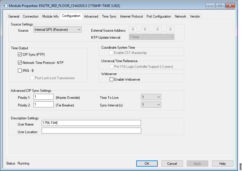
The module should be configured to use the internal GPS receiver as the source and output CIP Sync time. The priority1 and priority2 values should be set so the module becomes the primary or secondary grandmaster as desired. Optionally, the NTP server can be enabled so the module becomes a stratum 1 NTP server.
Logix PAC
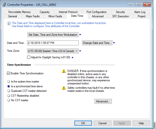
The Logix PAC® system is configured by editing the controller properties in Studio 5000 Logix Designer. On the Date/Time tab, the Enable Time Synchronization checkbox must be selected to configure the controller for time synchronization. If the controller will be used as the reference clock, the Set Date, Time and Zone from Workstation button can be used to set the controller’s real-time clock based on the configuration of the computer running Studio 5000 Logix Designer.
Figure 3-2 PAC Date and Time Configuration
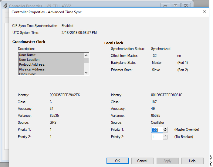
The Advanced button allows you to configure the priority1 and priority2 values of the controller. These values will vary depending on if the controller is designated to be a member of the grandmaster tier or controller tier.
Figure 3-3 PAC PTP Advanced Configuration
Communication Adapters
It is important to configure the communication adapters to support CIP Sync. Some Rockwell Automation platforms, such as the 5069-AEN2TR, have CIP Sync enabled by default. Other platforms, such as the 1756-EN2T family, require manual configuration to enable CIP Sync. Refer to vendor documentation for instructions on configuring your communications adapter.
I/O Points
CIP Sync applications require configuring the individual I/O points for time stamping. The time stamping features of the module will vary from module to module. In addition, the configuration of the I/O points may vary depending on the module selected and the application. Refer to vendor documentation for instructions on configuring your I/O points.
Industrial Ethernet Switches
There are three options for configuring PTP in the IES:
The configuration choice will depend on the IES platform selected and preferences of the installer. The Allen-Bradley Stratix IES support all three configuration methods, while the Cisco IE IES only support command line and Device Manager. However, not all the PTP configuration options used in this CPwE Time solution are available in the Device Manager or Studio 5000 Logix Designer. These configuration options must be done via the command line interface.

Note![]() Use caution when setting the sync limit below 50,000. This setting should only be used in IACS applications where the grandmaster has a very high-precision clock and all the IES have hardware support for PTP enabled.
Use caution when setting the sync limit below 50,000. This setting should only be used in IACS applications where the grandmaster has a very high-precision clock and all the IES have hardware support for PTP enabled.
Command Line
Step 1![]() Configure the IES for boundary clock mode:
Configure the IES for boundary clock mode:
Step 2![]() Configure the boundary clock to use the feedforward transfer function:
Configure the boundary clock to use the feedforward transfer function:
Step 3![]() Configure the time properties to persist infinitely:
Configure the time properties to persist infinitely:
Step 4![]() Configure the priority1 value for the infrastructure tier:
Configure the priority1 value for the infrastructure tier:
Step 5![]() Configure the priority2 value for the infrastructure tier:
Configure the priority2 value for the infrastructure tier:
Step 6![]() Configure the interfaces to use a sync limit of 10,000:
Configure the interfaces to use a sync limit of 10,000:
The sync limit should be configured on all boundary clock interfaces. This can either be done individually or with the interface range configuration command.
Device Manager
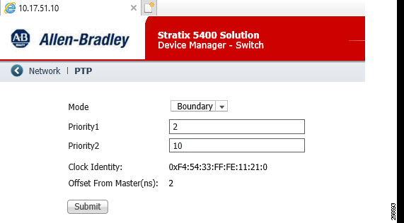
PTP is configured in the Device Manager by selecting the PTP option under the Configure menu.
Step 1![]() Configure the IES for boundary clock mode.
Configure the IES for boundary clock mode.
Step 2![]() Configure the priority1 value for the infrastructure tier.
Configure the priority1 value for the infrastructure tier.
Step 3![]() Configure the priority2 value for the infrastructure tier.
Configure the priority2 value for the infrastructure tier.
Figure 3-4 Stratix Device Manager PTP Clock Configuration
Step 4![]() Configure the interfaces to use a sync fault limit of 10,000.
Configure the interfaces to use a sync fault limit of 10,000.
Figure 3-5 Stratix Device Manager PTP Port Configuration
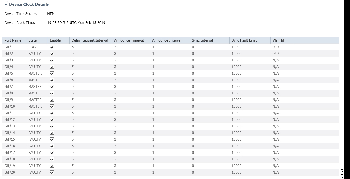
Several of the configuration items required for this CPwE Time solution can only be configured using the command line interface.
Step 5![]() Configure the boundary clock to use the feedforward transfer function:
Configure the boundary clock to use the feedforward transfer function:
Step 6![]() Configure the time properties to persist infinitely:
Configure the time properties to persist infinitely:
Studio 5000 Logix Designer
PTP is configured in the Time Sync Configuration section of the Allen-Bradley Stratix AOP.
Step 1![]() Configure the IES for boundary clock mode.
Configure the IES for boundary clock mode.
Step 2![]() Configure the priority1 value for the infrastructure tier.
Configure the priority1 value for the infrastructure tier.
Step 3![]() Configure the priority2 value for the infrastructure tier.
Configure the priority2 value for the infrastructure tier.
Step 4![]() Configure the interfaces to use a sync fault limit of 10,000.
Configure the interfaces to use a sync fault limit of 10,000.
Figure 3-6 Stratix Studio 5000 Logix Designer PTP Configuration
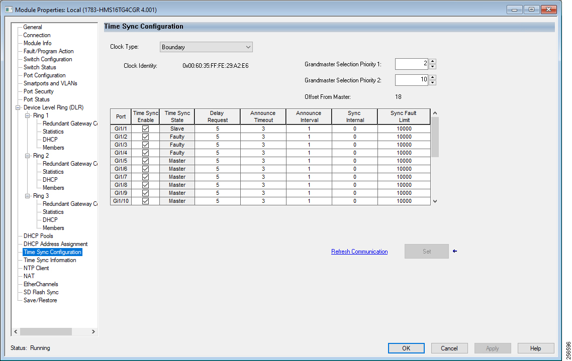
Several of the configuration items required for this CPwE Time solution can only be configured using the command line interface.
Step 5![]() Configure the boundary clock to use the feedforward transfer function:
Configure the boundary clock to use the feedforward transfer function:
Step 6![]() Configure the time properties to persist infinitely:
Configure the time properties to persist infinitely:
 Feedback