Installation, Maintenance, and Upgrade

Install, Remove, and Replace the Network Module

You can remove and replace the network module (NM-2) in the Secure Firewall 3100. Hot-swapping of identical modules is supported, but if you replace a network module with another type, you must reboot the system so that the new network module is recognized.

See the configuration guide for your operating system for the procedure for managing network modules.


Caution


You can install all supported network modules in all Secure Firewall 3100 models, but the 40-Gb network module (FPR-X-NM-4X40G) and the 1/10/25-Gb network module (FPR-X-NM-8X25G) are only recognized when installed in the 3130 and 3140. The software does not support these network modules for the 3105, 3110, and 3120.


This procedure describes how to install a network module into an empty slot that has never contained a network module, and how to remove an installed network module and replace it with another network module.

Safety Warnings

Take note of the following warning:


Warning


Statement 1073—No User-Serviceable Parts

There are no serviceable parts inside. To avoid risk of electric shock, do not open.


Procedure


Step 1

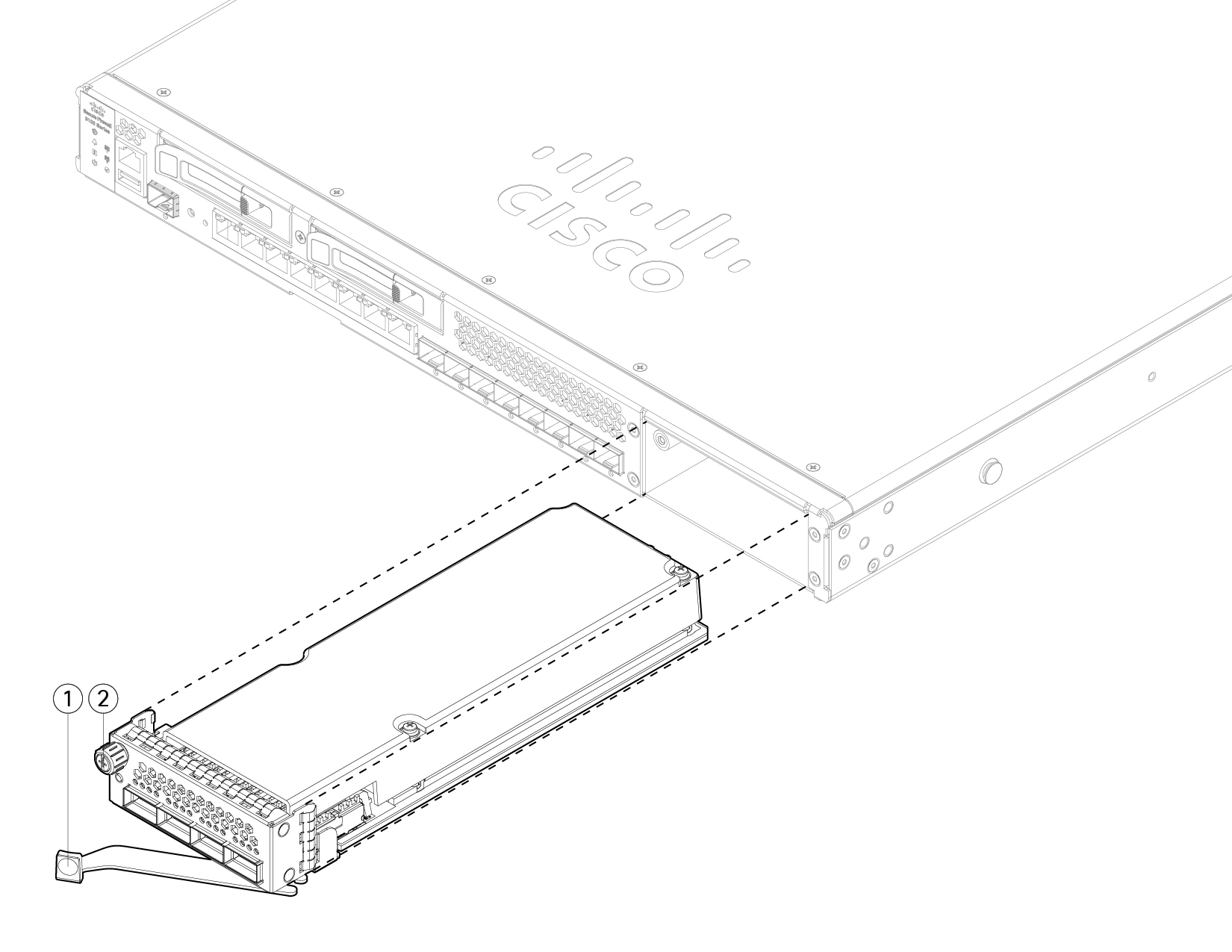
To install a network module for the first time into an empty slot, do the following:

  1. Power down the chassis by moving the power switch to the OFF position.

    See Rear Panel for more information about the power switch. See the configuration guide for your operating system for the procedure for installing a network module for the first time into an empty slot.
  2. Follow Steps 4 through 7 to install the new network module.

  3. Power on the chassis by moving the power switch to the ON position.

Step 2

To remove and replace an existing network module, do the following:

  1. Save your configuration.

  2. To replace an existing network module with the same model network module, disable the network slot. See the configuration guide for your operating system for the procedure to replace an existing network module with the same model.

  3. To replace an existing network module with a different model network module, power down the chassis by moving the power switch to the OFF position. See the configuration guide for your operating system for the procedure to replace an existing network module with a new model.

    See Rear Panel for more information about the power switch.
  4. Continue with Step 3.

Step 3

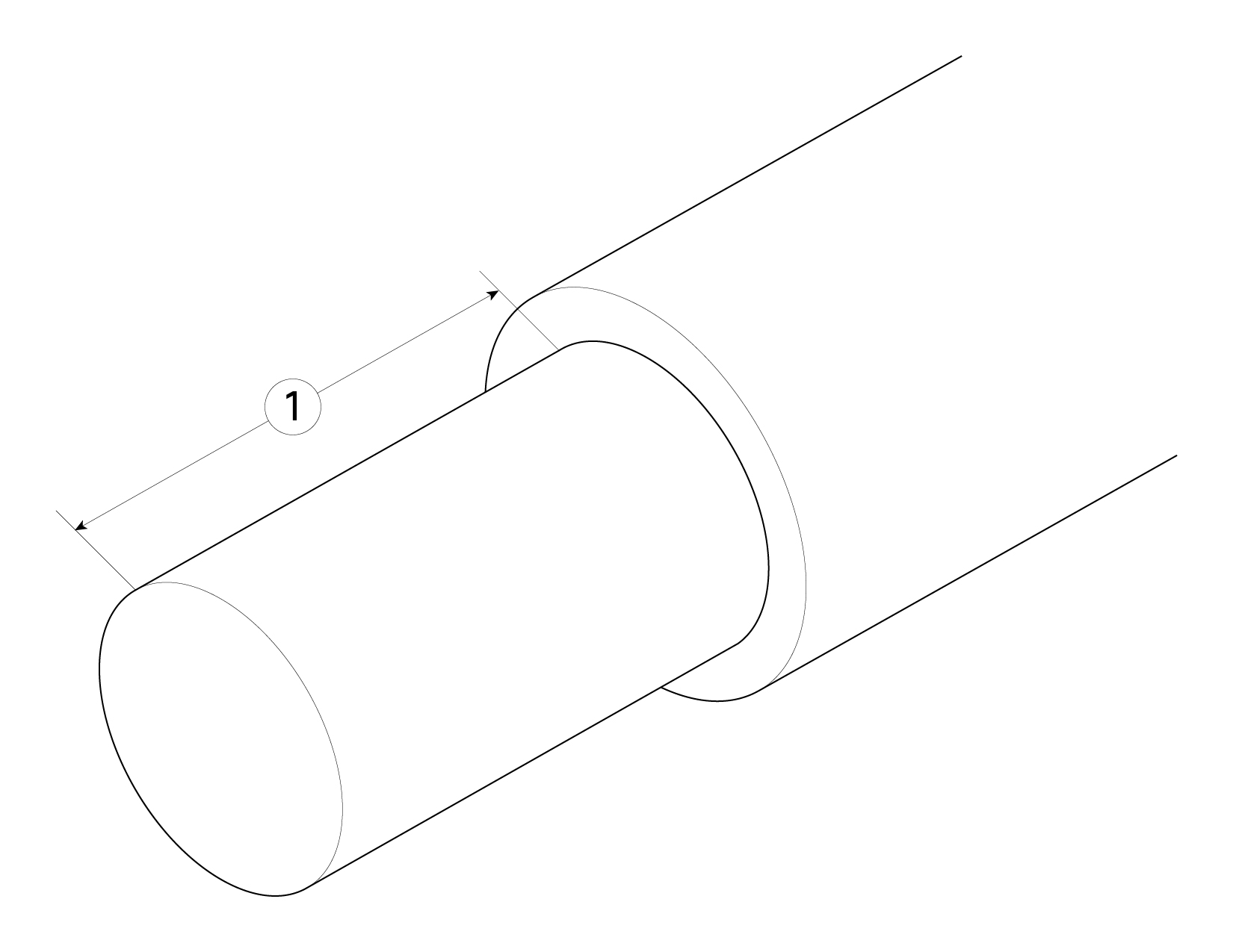
To remove a network module, loosen the captive screw on the upper left side of the network module, press the handle ejector, and pull out the handle. This mechanically ejects the network module from the slot.

Caution


The captive screw is not attached to the handle. Be sure the captive screw is completely loosened before pulling the ejector handle out. Otherwise you could damage the ejector handle as the captive screw and handle fight each other.

Figure 1. Remove the Network Module

1

Ejector handle

2

Captive screw

If the slot is to remain empty, install a blank faceplate to ensure proper airflow and to keep dust out of the chassis; otherwise, install another network module.

Step 4

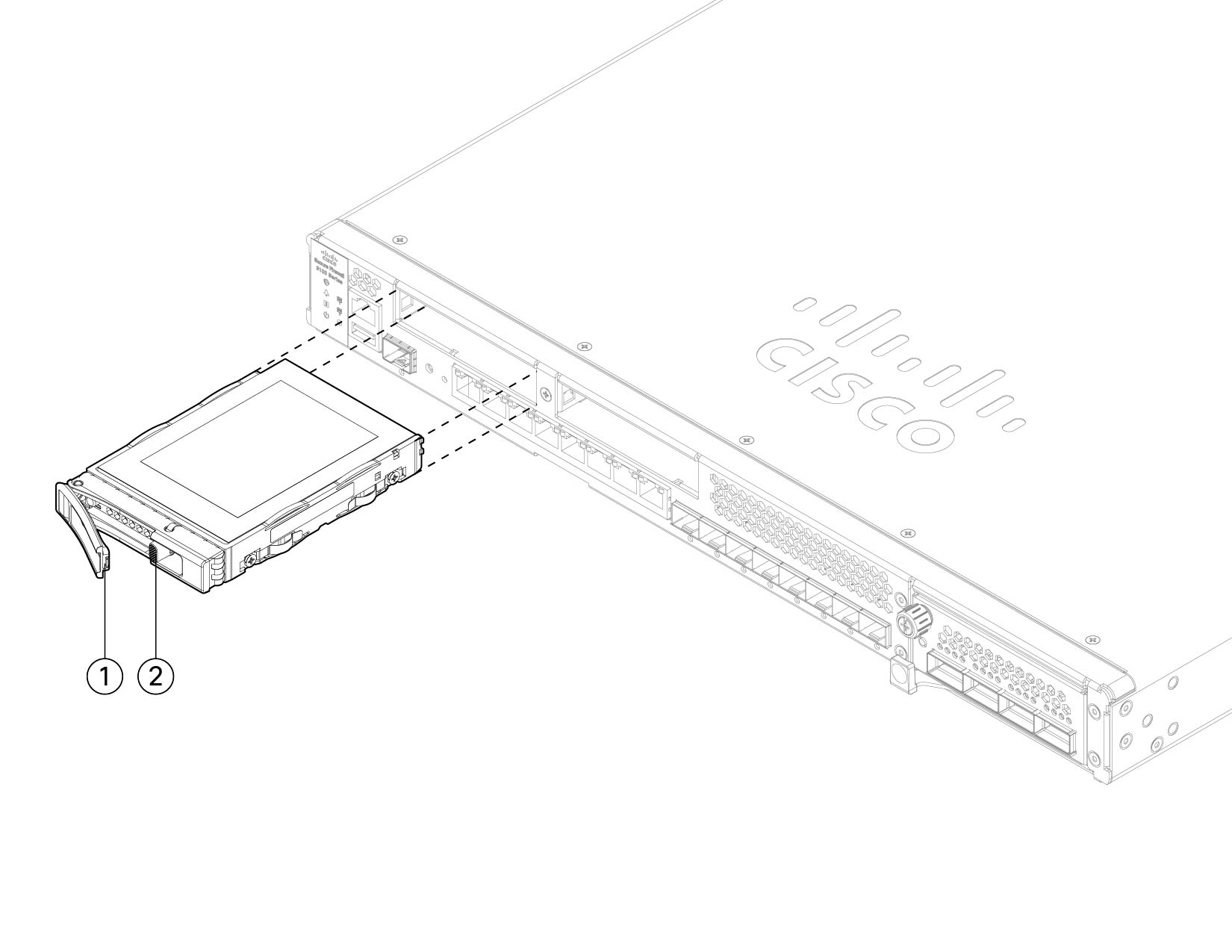
To replace a network module, hold the network module in front of the network module slot on the right of the chassis, press the ejector handle, and pull out the handle.

Step 5

Slide the network module into the slot, push it firmly into place, and close the handle on the front of the network module.

Step 6

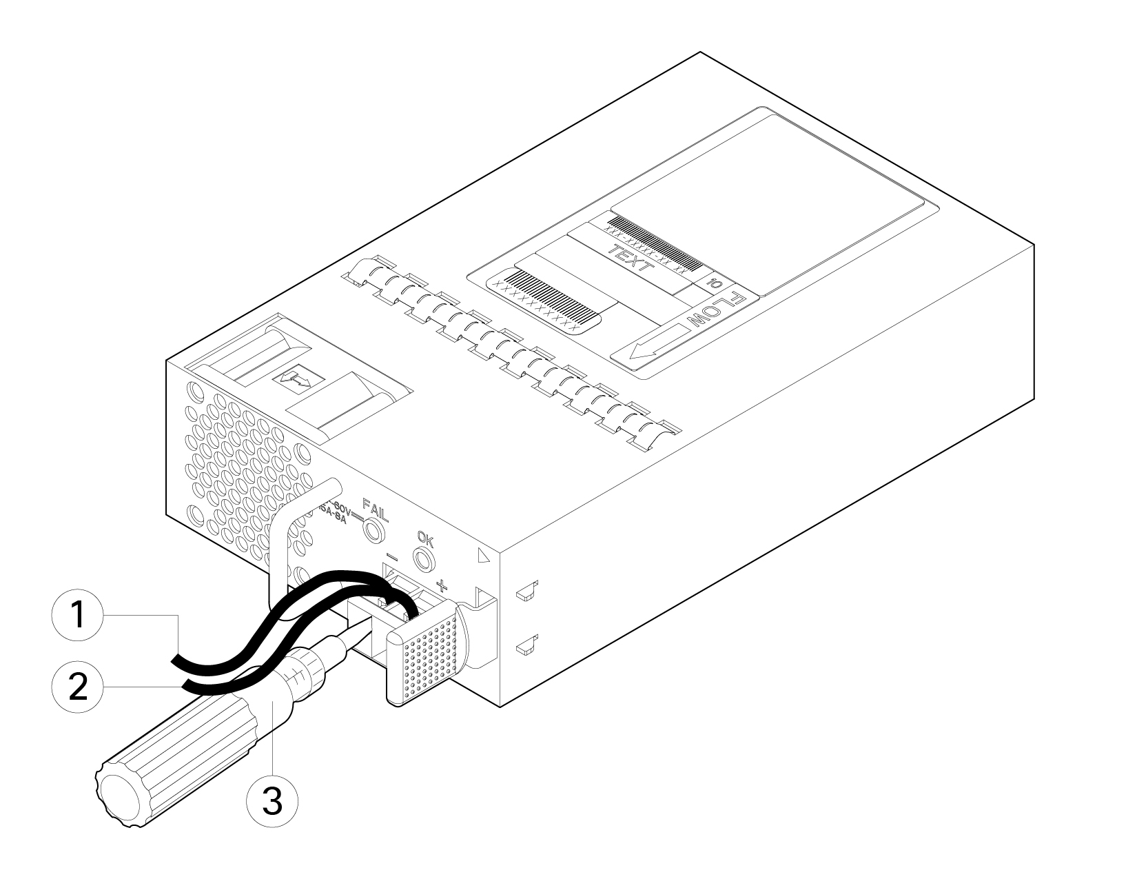
Tighten the captive screw on the upper left side of the network module.

Step 7

Power on the chassis so that the new network module is recognized.


Remove and Replace the SSD

The chassis supports two NVMe SSDs. The first SSD slot (SSD-1) is for storage. The second slot (SSD-2) is for the optional SW RAID1 support only. See SSDs for more information.


Caution


Hot swapping for the RAID configuration is not supported. You can hot-swap SSD-1 if there are two SSDs installed. To hot-swap SSD-2, you must remove it from the RAID configuration using the raid remove-secure local-disk 1|2 command. See Hot Swap an SSD on the Secure Firewall 3100/4200 for the procedures for safely removing an SSD.


Safety Warnings

Take note of the following warning:


Warning


Statement 1073—No User-Serviceable Parts

There are no serviceable parts inside. To avoid risk of electric shock, do not open.


Procedure


Step 1

Save your configuration.

Step 2

If you are removing SSD-1 and there is only one SSD installed in the chassis, power down the chassis by moving the power switch to the OFF position. See Rear Panel for more information on the power switch.

You can only remove the SSD in slot 1 if there are two SSDs installed. If you have only one SSD, you cannot remove it while the chassis is powered on

Step 3

To remove the SSD in slot 1, face the front of the chassis, and pinch the release tab on the front of the SSD. This causes the ejector handle to spring open.

Step 4

Grasp the ejector handle to gently pull the SSD out of the chassis.

Figure 2. Remove the SSD

1

Ejector handle

SSD release tab

Step 5

To replace the SSD in slot 1, make sure the power switch is still in the OFF position (if you are replacing SSD-1), and then hold the SSD with the ejector handle extended in front of slot 1, push it in gently until it is seated, and close the ejector handle.

Step 6

You can install the RAID1 SSD in slot 2. Make sure the power switch is still in the OFF position, and then remove the blank faceplate in slot 2 by loosening the handle on the faceplate.

Step 7

Hold the RAID1 SSD with the ejector handle extended in front of slot 2, push it in gently until it is seated, and close the ejector handle.

Caution


Do not switch the two SSDs. The RAID1 SSD must be installed in slot 2.

Step 8

Check the SSD LED to make sure the SSD is operative. See Front Panel LEDs for a description of the SSD LEDs.

Step 9

Add SSD-2 to the RAID configuration using the raid add local-disk 1|2 command.


Remove and Replace the Dual Fan Module

You can remove and replace the dual fan modules while the chassis is running. There are two dual fan modules in the rear of the chassis. The air flow moves from front to back (I/O side to non-I/0 side).


Caution


Removing both dual fan modules exposes the chassis to no airflow. The chassis operates for 30 seconds after either one or both modules are removed. All modules must be reinserted within 30 seconds to avoid overheating the chassis. If you wait longer than 30 seconds, the chassis may power off automatically to prevent damage to components. The chassis does not power up and boot properly if the dual fan modules are missing.


Safety Warnings

Take note of the following warnings:


Warning


Statement 1073—No User-Serviceable Parts

There are no serviceable parts inside. To avoid risk of electric shock, do not open.


Warning


Statement 1093—Avoid Sharp Edges

Risk of personal injury. Avoid sharp edges when installing or removing replaceable units.


Procedure


Step 1

Have the dual fan module ready for immediate insertion and near the chassis so that you can reinstall it within 30 seconds.

Step 2

To remove a fan module, face the rear of the chassis, and press the squeeze tabs on the sides of the fan module to loosen it from the chassis.

Step 3

Grasp the handle and pull the fan module out of the chassis.

Figure 3. Remove the Dual Fan Module

1

Handle

Squeeze tabs

Step 4

To replace a fan module, hold the fan module in front of the fan slot.

Step 5

Press the squeeze tabs on the sides of the fan module and push the it into the chassis.

Step 6

Grasp the handle and push until the fan module is properly seated.

If the system is powered on, listen for the fans. You should immediately hear the fans operating. If you do not hear the fans, make sure the fan module is inserted completely into the chassis and the faceplate is flush with the outside surface of the chassis.

Step 7

Verify that the fan is operational by checking the fan module LED. See Front Panel LEDs for a description of the fan LEDs.


Remove and Replace the Power Supply Module

Power supply modules are hot-swappable. You can remove and replace power supply modules while the system is running.

Safety Warnings

Take note of the following warnings:


Warning


Statement 1003—DC Power Disconnection

To reduce risk of electric shock or personal injury, disconnect DC power before removing or replacing components or performing upgrades.


Warning


Statement 1015—Battery Handling

To reduce risk of fire, explosion or leakage of flammable liquid or gas:

  • Replace the battery only with the same or equivalent type recommended by the manufacturer.

  • Do not dismantle, crush, puncture, use sharp tool to remove, short external contacts, or dispose of in fire.

  • Do not use if battery is warped or swollen.

  • Do not store or use battery in a temperature > 60° C.

  • Do not store or use battery in low air pressure environment < 69.7 kPa.


Warning


Statement 1022—Disconnect Device

To reduce the risk of electric shock and fire, a readily accessible disconnect device must be incorporated in the fixed wiring.


Warning


Statement 1046—Installing or Replacing the Unit

To reduce risk of electric shock, when installing or replacing the unit, the ground connection must always be made first and disconnected last.

If your unit has modules, secure them with the provided screws.


Warning


Statement 1073—No User-Serviceable Parts

There are no serviceable parts inside. To avoid risk of electric shock, do not open.


Procedure


Step 1

Unplug the power supply cable before removing the power supply module. You cannot disengage the power supply module release tab without first removing the cable.

Step 2

To remove a power supply module, face the back of the chassis and grasp the handle.

Step 3

Press the release tab toward the left to disengage the power supply. The release tab is found on the right side of the power supply.

Step 4

Place your other hand under the power supply module to support it while you slide it out of the chassis.

Figure 4. Remove the Power Supply Module

1

Release tab

Handle

If the slot is to remain empty, install a blank faceplate to ensure proper airflow and to keep dust out of the chassis; otherwise, install another power supply module.

Step 5

To replace a power supply module, hold the power supply module with both hands and slide it into the power supply module bay.

Step 6

Push in the power supply module gently until you hear the release tab engage and the power supply is seated.

Step 7

Plug in the power supply cable.

Step 8

Check the LED on the power supply to make sure the power supply is operative. See Power Supply Module for a description of the LEDs.


Connect the DC Power Supply Module

The input connector and plug must be UL recognized under UL 486 for field wiring. The connection polarity is from left to right: negative (–), positive (+), and ground.

Use the handle on the power supply installation and removal. You must support the module with one hand because of its length.

Figure 5. DC Power Supply Module

1

Handle

2

FAIL and OK LEDs

3

DC power connector

4

Ejector latch

Safety Warnings

Take note of the following warning:


Warning


Statement 1073—No User-Serviceable Parts

There are no serviceable parts inside. To avoid risk of electric shock, do not open.


Before you begin

  • The color coding of the DC input power supply leads depends on the color coding of the DC power source at your site. Make sure that the lead color coding you choose for the DC input power supply matches the lead color coding used at the DC power source and verify that the power source is connected to the negative (–) terminal and to the positive (+) terminal on the power supply.

  • Make sure that the chassis ground is connected on the chassis before you begin installing the DC power supply. See Ground the Chassis for the procedure.

Procedure


Step 1

Verify that the power is off to the DC circuit on the power supply module that you are installing.

Step 2

While supporting the power supply module with one hand, insert the power supply module into the power supply bay and gently push it in. See the illustration above for the location of the handle.

Step 3

Use a wire-stripping tool to strip each of the two wires coming from the DC input power source. Strip the wires to approximately 0.39 inch (10 mm) + 0.02 inch (0.5 mm). We recommend you use 14 AWG insulated wire.

Note


Do not strip more than the recommended length of wire because doing so could leave the wire exposed from the terminal block.

Figure 6. Stripped DC Input Source Wire

1

Strip the wires to approximately 0.39 inch (10 mm) + 0.02 inch (0.5 mm)

Step 4

Insert the exposed wire into the terminal block. Ensure that you cannot see any wire lead outside the plastic cover. Only wires with insulation should extend from the terminal block.

Step 5

Use a screwdriver to tighten the terminal block captive screws.

Caution


Do not over torque the terminal block captive screws. Make sure that the connection is snug, but the wire is not crushed. Verify by tugging lightly on each wire to make sure that they do not move.

Figure 7. Tighten the Terminal Block Captive Screws

1

Negative (-) lead wire

2

Positive (+) lead wire

3

Screwdriver

Step 6

Repeat these steps for the remaining DC input power source wire as applicable.

Step 7

Use a tie wrap so secure the wires to the rack, so that the wires are not pulled from the terminal block.

Step 8

Set the DC disconnect switch in the circuit to ON. In a system with multiple power supplies, connect each power supply to a separate DC power source. In the event of a power source failure, if the second source is still available, it can maintain system operation.

Step 9

Verify power supply operation by checking the power supply LED on the front of the chassis. See Front Panel LEDs for the LED values.


Secure the Power Cord on the Power Supply Module

To secure the power supply module against accidental removal and thus prevent disrupting system performance, use the tie wrap and clamp provided in the accessories kit that ships with your Secure Firewall 3100 series.

Safety Warnings

Take note of the following warning:


Warning


Statement 1073—No User-Serviceable Parts

There are no serviceable parts inside. To avoid risk of electric shock, do not open.


Procedure


Step 1

Attach the clamp to the tie wrap by holding the clamp with the loop side on the bottom and sliding the tie wrap through the box-shaped channel above the clamp (see the following figure).

One side of the tie wrap has evenly spaced ridges and the other is smooth. Be sure the ridged side is face up and that you slide it through the open side of the channel. You hear a click as the tie slides through—it moves in one direction only. To remove the tie wrap from the clamp, push the lever on the closed side of the box-shaped channel and slide out the tie wrap.

Figure 8. Tie Wrap Through the Box Channel of the Clamp

1

Tie wrap

2

Box channel

Step 2

Attach the clamp to the power supply module:

  1. Locate the hexagonal ventilation hole on the power supply module at the center of the plug just below the power connector body (see the following figures).

  2. Plug the snapping portion of the tie wrap into the hexagonal hole.

  3. With the clamp side facing up, push the tie wrap in until it is fully engaged.

    Caution


    Make sure you have the correct location because you cannot remove the tie wrap from the power supply module once you have installed it without damaging the tie wrap.

    Figure 9. Connect the Tie Wrap

    1

    Tie wrap

    2

    Hexagonal hole

Step 3

Secure the clamp:

  1. Plug in the power cord into the power supply module and wrap the clamp around the over mold portion of the power cord.

  2. Squeeze the clamp ends together so that the annular teeth engage with the mate on the clamp.

  3. Make sure the clamp fits snugly into the over mold.

  4. Adjust the clamp position on the tie wrap so that the clamp is tight against the front of the over mold and the power cord cannot be removed by lightly pulling on it.

    Figure 10. Clamp on Over Mold of Power Cord

    1

    Power cord

    2

    Power cord over mold

    Clamp release tab

    3

    Tie clamp annular teeth

    4

    Direction to squeeze the clamp ties

    5

    Clamp release tabs

Step 4

If you need to remove the power cord, push the release tab on the clamp to force the annular clamp teeth to disengage and the clamp opens up. You can then remove the clamp from the power cord.