Configure a Basic Policy

Configure a basic security policy with the following settings:

  • Inside and outside interfaces—Assign a static IP address to the inside interface, and use DHCP for the outside interface.

  • DHCP server—Use a DHCP server on the inside interface for clients.

  • Default route—Add a default route through the outside interface.

  • NAT—Use interface PAT on the outside interface.

  • Access control—Allow traffic from inside to outside.

You can also ccustomize your security policy to include more advanced inspections.

Configure Interfaces

When you use zero-touch provisioning or the device manager for initial setup instead of using the CLI, the following interfaces are preconfigured:

  • Ethernet 1/1—outside, IP address from DHCP, IPv6 autoconfiguration

  • VLAN1— inside, 192.168.95.1/24

  • Default route—Obtained through DHCP on the outside interface

If you performed additional interface-specific configuration within device manager before registering with the management center, then that configuration is preserved.

If you used the CLI for initial setup, there is no preconfiguration of your device.

In both cases, you need to perform additional interface configuration after you register the device. For CLI initial setup, you must add the VLAN1 interface for the inside switch ports. Additional configuration includes converting switch ports to firewall interfaces as desired, assigning interfaces to security zones, and changing IP addresses.

The following example configures a routed-mode inside interface (VLAN1) with a static address and a routed-mode outside interface using DHCP (Ethernet1/1). It also adds a DMZ interface for an internal web server.

Procedure


Step 1

Choose Devices > Device Management, and click Edit (edit icon) for the device.

Step 2

Click Interfaces.

Figure 1. Interfaces
Interfaces

Step 3

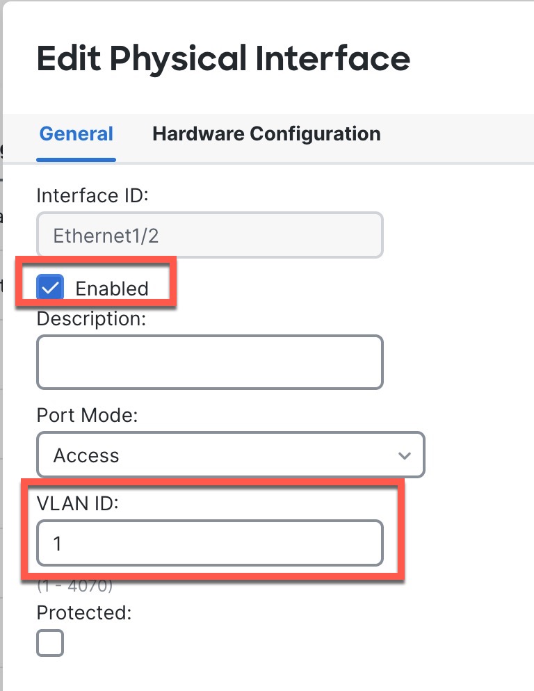
If you used the CLI for initial setup, enable the switch ports.

  1. Click Edit (edit icon) for the switch port.

    Figure 2. Enable Switch Port
    Enable Switch Port
  2. Enable the interface by checking the Enabled check box.

  3. (Optional) Change the VLAN ID; the default is 1. You will next add a VLAN interface to match this ID.

  4. Click OK.

Step 4

Add (or edit) the inside VLAN interface.

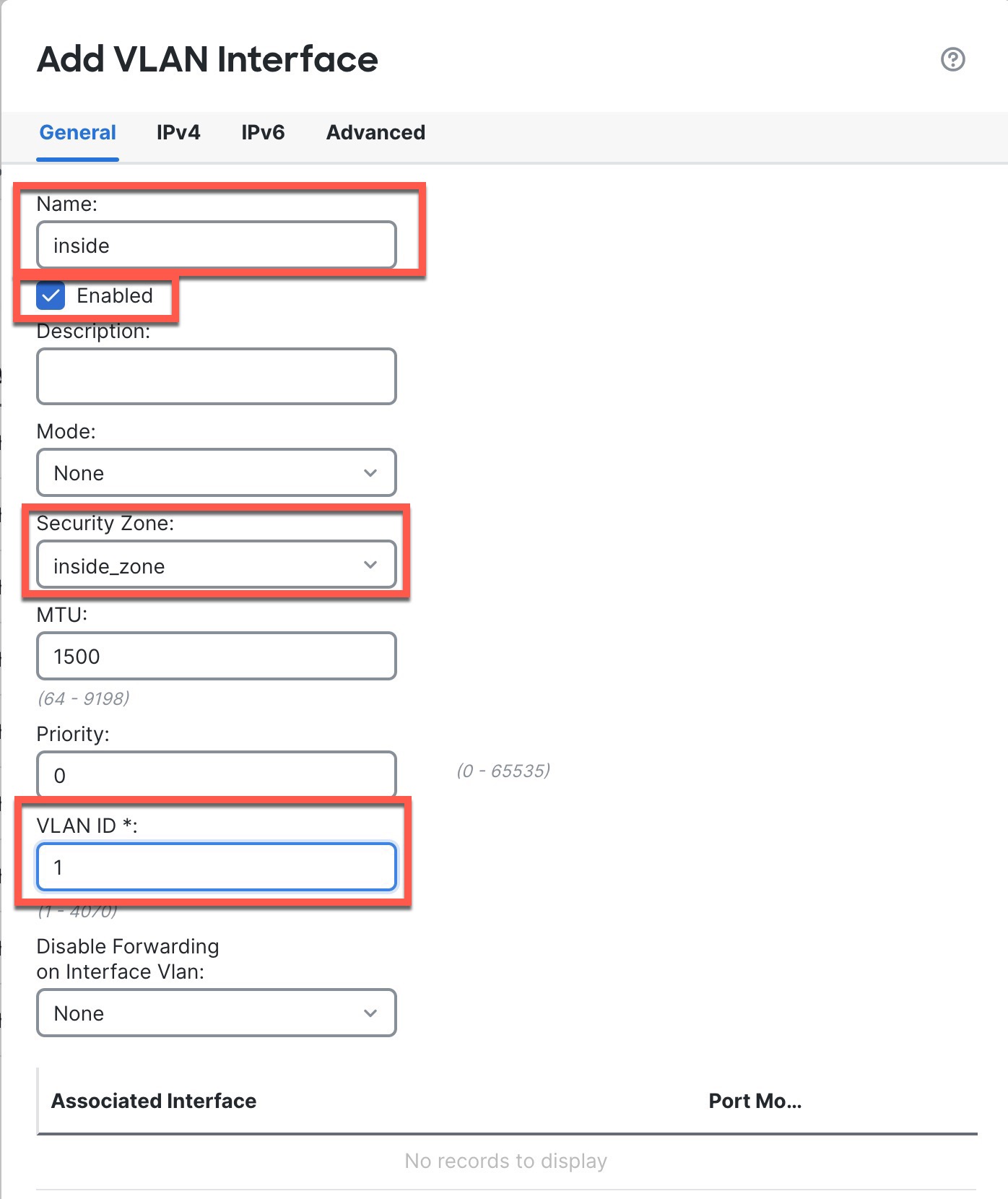
  1. Click Add Interfaces > VLAN Interface, or if this interface already exists, click Edit (edit icon) for the interface.

    Figure 3. Add VLAN Interface
    Add VLAN Interface
  2. From the Security Zone drop-down list, choose an existing inside security zone or add a new one by clicking New.

    For example, add a zone called inside_zone. You apply your security policy based on zones or groups.

    If VLAN1 was preconfigured, the rest of these fields are optional.

  3. Enter a Name up to 48 characters in length.

    For example, name the interface inside.

  4. Check the Enabled check box.

  5. Leave the Mode set to None.

  6. Set the VLAN ID to 1.

    By default, all of the switchports are set to VLAN 1; if you choose a different VLAN ID here, you need to also edit each switchport to be on the new VLAN ID.

    You cannot change the VLAN ID after you save the interface; the VLAN ID is both the VLAN tag used, and the interface ID in your configuration.

  7. Click the IPv4 and/or IPv6 tab.

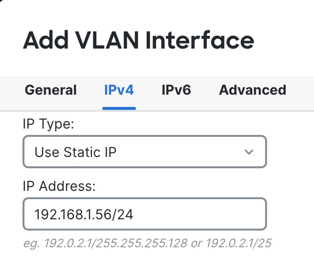
    • IPv4—Choose Use Static IP from the drop-down list, and enter an IP address and subnet mask in slash notation.

      For example, enter 192.168.1.56/24

      Figure 4. Set Inside IP Address
      Set Inside IP Address
    • IPv6—Check the Autoconfiguration check box for stateless autoconfiguration.

  8. Click OK.

Step 5

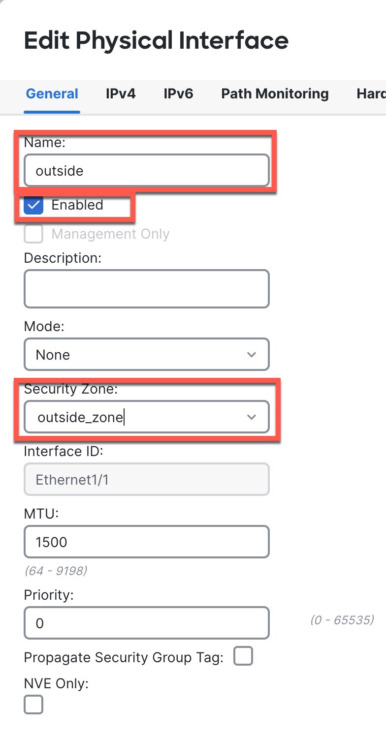
Click Edit (edit icon) for Ethernet1/1 that you want to use for outside.

The General page appears.

Figure 5. General
General
  1. From the Security Zone drop-down list, choose an existing outside security zone or add a new one by clicking New.

    For example, add a zone called outside_zone.

    You should not alter any other basic settings because doing so will disrupt the management center management connection.

  2. Click OK.

Step 6

Configure a DMZ interface to host a web server, for example.

  1. Disable switch-port mode for the switch port you want to use for the DMZ by clicking the slider in the SwitchPort column so it shows as disabled (slider disabled).

  2. Click Edit (edit icon) for the interface.

  3. From the Security Zone drop-down list, choose an existing DMZ security zone or add a new one by clicking New.

    For example, add a zone called dmz_zone.

  4. Enter a Name up to 48 characters in length.

    For example, name the interface dmz.

  5. Check the Enabled check box.

  6. Leave the Mode set to None.

  7. Click the IPv4 and/or IPv6 tab and configure the IP address as desired.

  8. Click OK.

Step 7

Click Save.


Configure the DHCP Server

Enable the DHCP server if you want clients to use DHCP to obtain IP addresses from the firewall.

Procedure


Step 1

Choose Devices > Device Management, and click Edit (edit icon) for the device.

Step 2

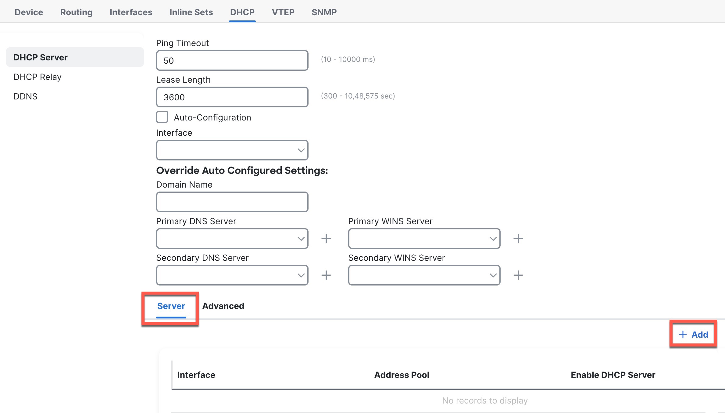
Choose DHCP > DHCP Server.

Figure 6. DHCP Server
DHCP Server

Step 3

In the Server area, click Add and configure the following options.

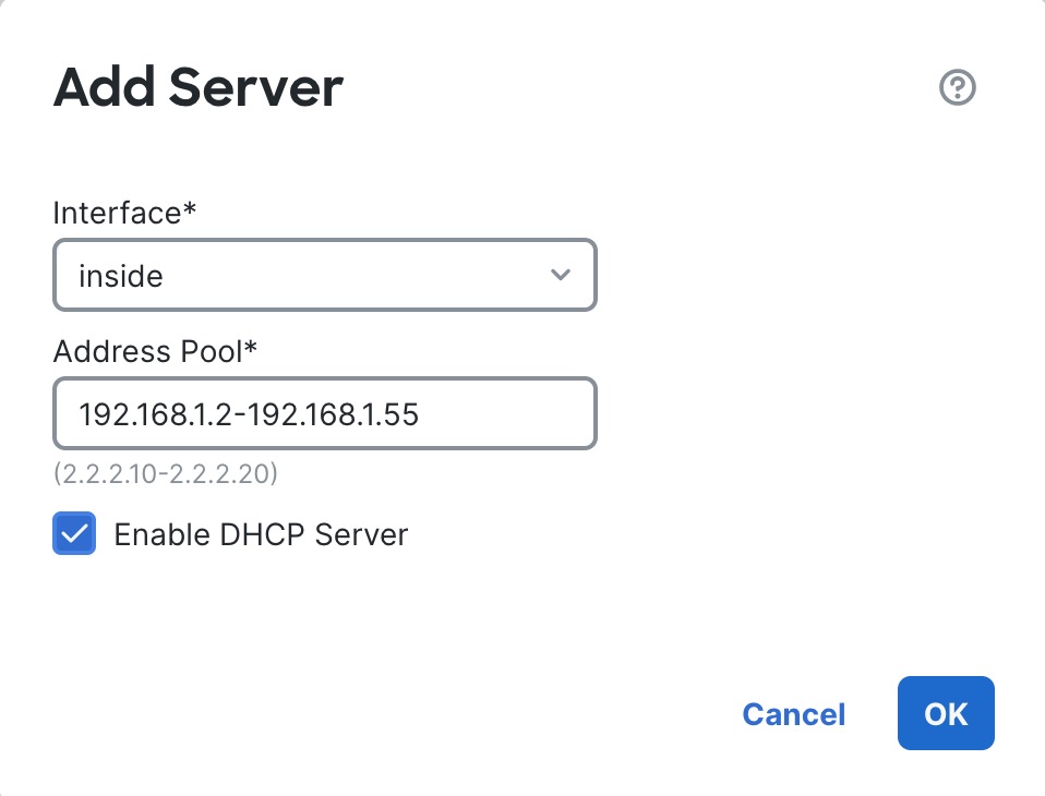
Figure 7. Add Server
Add Server
  • Interface—Choose the interface name from the drop-down list.

  • Address Pool—Set the range of IP addresses. The IP addresses must be on the same subnet as the selected interface and cannot include the IP address of the interface itself.

  • Enable DHCP Server—Enable the DHCP server on the selected interface.

Step 4

Click OK.

Step 5

Click Save.


Configure NAT

This procedure creates a NAT rule for internal clients to convert the internal addresses to a port on the outside interface IP address. This type of NAT rule is called interface Port Address Translation (PAT).

Procedure


Step 1

Choose Devices > NAT, and click New Policy.

Step 2

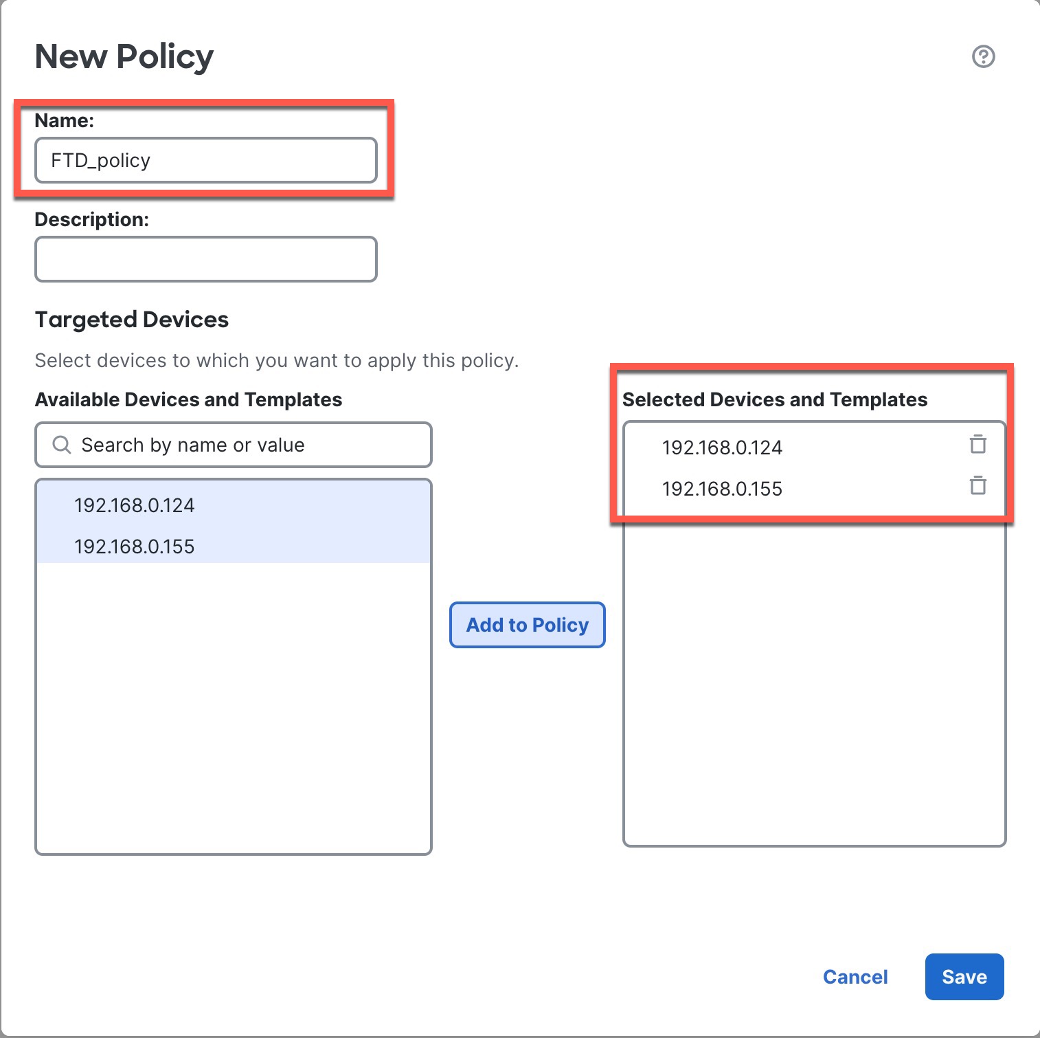
Name the policy, select the devices that you want to use the policy, and click Save.

Figure 8. New Policy
New Policy

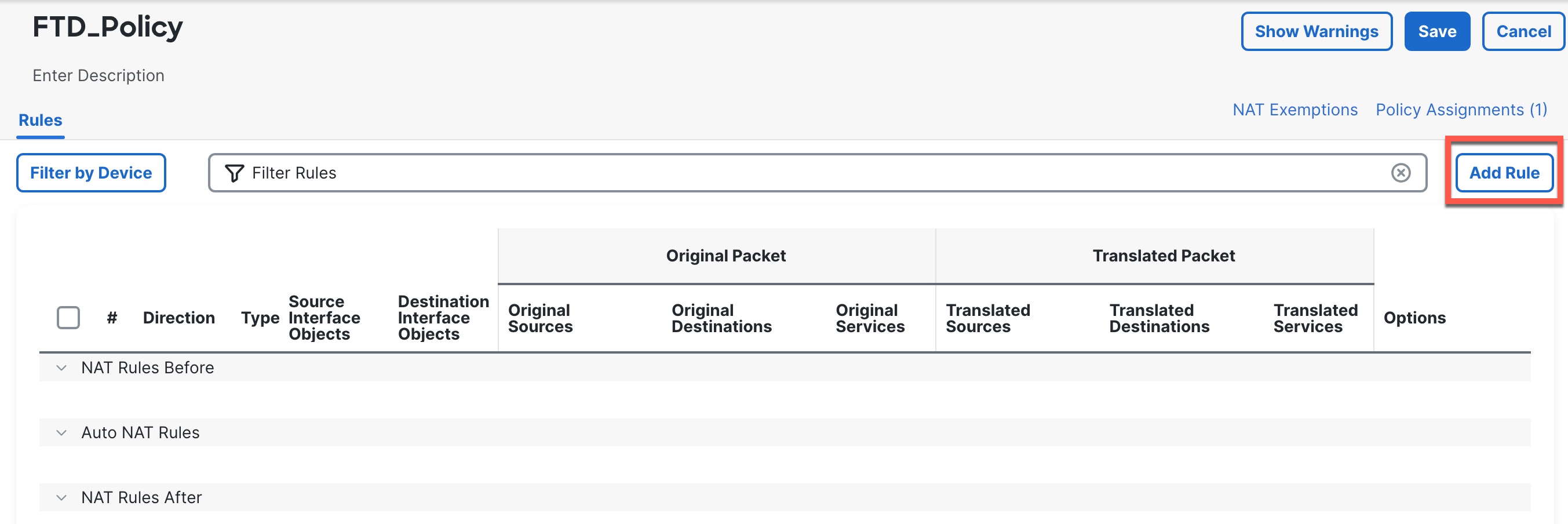
The policy is added the management center. You still have to add rules to the policy.

Figure 9. NAT Policy
NAT Policy

Step 3

Click Add Rule.

Step 4

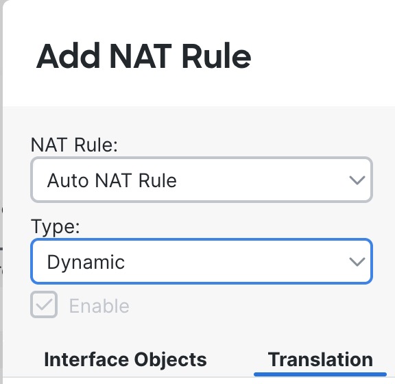
Configure the basic rule options:

Figure 10. Basic Rule Options
Basic Rule Options
  • NAT Rule—Choose Auto NAT Rule.

  • Type—Choose Dynamic.

Step 5

On the Interface Objects page, add the outside zone from the Available Interface Objects area to the Destination Interface Objects area.

Figure 11. Interface Objects
Interface Objects

Step 6

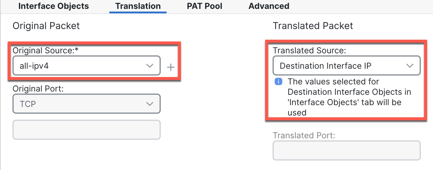
On the Translation page, configure the following options:

Figure 12. Translation
Translation
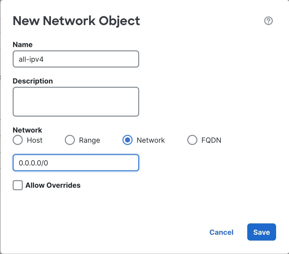
  • Original Source—Click Add (add icon) to add a network object for all IPv4 traffic (0.0.0.0/0).

    Figure 13. New Network Object
    New Network Object

    Note


    You cannot use the system-defined any-ipv4 object, because Auto NAT rules add NAT as part of the object definition, and you cannot edit system-defined objects.

  • Translated Source—Choose Destination Interface IP.

Step 7

Click Save to add the rule.

The rule is saved to the Rules table.

Step 8

Click Save on the NAT page to save your changes.


Configure an Access Control Rule

If you created a basic Block all traffic access control policy when you registered the device, then you need to add rules to the policy to allow traffic through the device. The access control policy can include multiple rules that are evaluated in order.

This procedure creates an access control rule to allow all traffic from the inside zone to the outside zone.

Procedure


Step 1

Choose Policy > Access Policy > Access Policy, and click Edit (edit icon) for the access control policy assigned to the device.

Step 2

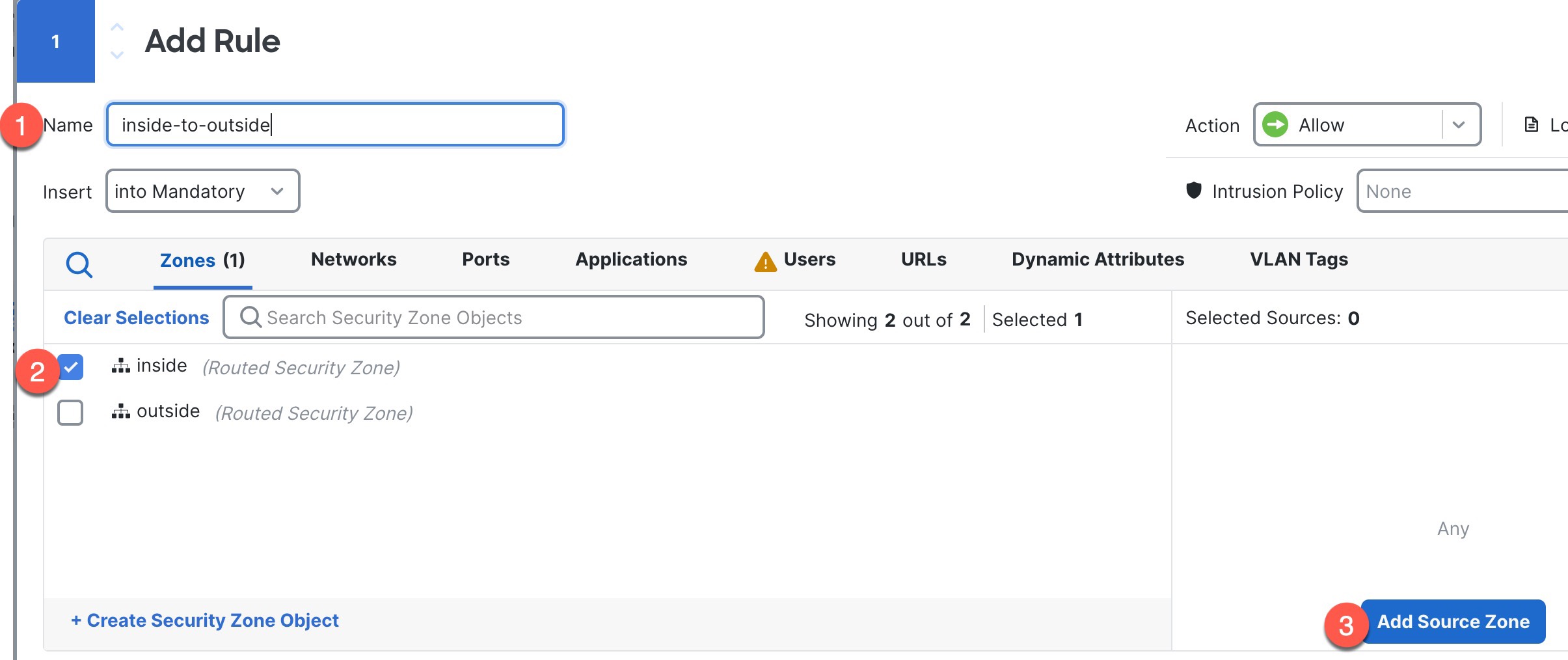
Click Add Rule, and set the following parameters.

Figure 14. Source Zone
Source Zone

1. Name this rule, for example, inside-to-outside.

2. Select the inside zone from Zones

3. Click Add Source Zone.

Figure 15. Destination Zone
Destination Zone

4. Select the outside zone from Zones.

5. Click Add Destination Zone.

Leave the other settings as is.

Step 3

(Optional) Customize associated policies by clicking on the policy type in the packet flow diagram.

Prefilter, Decryption, Security Intelligence, and Identity policies are applied before an access control rule. Customizing these policies is not required, but after you know your network's needs, they let you improve network performance by either fastpathing trusted traffic (bypassing processing) or blocking traffic so no further processing is required.

Figure 16. Policies Applied Before Access Control
Policies Applied Before Access Control
  • Prefilter Rules—The Default Prefilter Policy passes all traffic for the other rules to act on (analyzes). The only change to the default policy you can make is to block tunnel traffic. Otherwise, you can create a new prefilter policy to associate with the access control policy that can analyze (pass on), fastpath (bypass further checks) or block.

    Prefiltering lets you improve performance by dealing with traffic before it gets any further, by either blocking or fastpathing. In a new policy, you can add tunnel rules and prefilter rules. A tunnel rule lets you fastpath, block, or rezone plaintext (non-encrypted), passthrough tunnels. A prefilter rule lets you fastpath or block non-tunneled traffic identified by IP address, port, and protocol.

    For example, if you know you want to block all FTP traffic on your network, but fastpath SSH traffic from an administrator, you can add a new prefilter policy.

  • Decryption—Decryption is not applied by default. Decryption is a way to expose network traffic to deep inspection. In most cases, you don't want to decrypt traffic, and can only do so if it is legally allowed. For maximum network protection, a decryption policy might be a good idea for traffic going to critical servers or coming from untrusted network segments.

  • Security Intelligence—(Requires the IPS license) Security Intelligence is enabled by default. Security Intelligence is another early defense against malicious activity applied before passing connections to the access control policy for further processing. Security Intelligence uses reputation intelligence to quickly block connections to or from IP addresses, URLs, and domain names provided by Talos, the threat intelligence organization at Cisco. You can add or delete additional IP addresses, URLs, or domains if desired.

    Note


    If you do not have the IPS license, this policy will not be deployed even though it shows in your access control policy as enabled.

  • Identity—Identity is not applied by default. You can require a user to authenticate before allowing traffic to be processed by the access control policy.

Step 4

(Optional) Add an Intrusion policy that is applied after the access control rule.

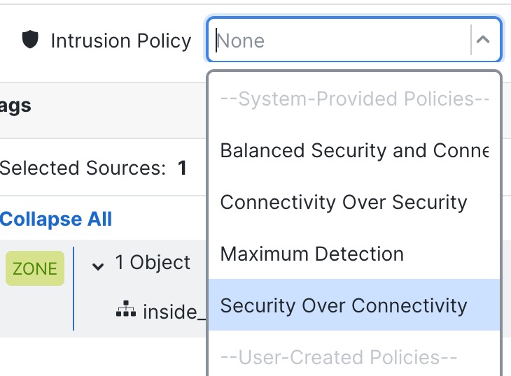
The Intrusion policy is a defined set of intrusion detection and prevention configurations that inspects traffic for security violations. The management center includes many system-provided policies you can enable as-is or that you can customize. This step enables a system-provided policy.

  1. Click the Intrusion Policy drop-down list.

    Figure 17. System-Provided Intrusion Policies
    System-Provided Intrusion Policies
  2. Choose one of the system-provided policies from the list.

Step 5

(Optional) Add a File policy that is applied after the access control rule.

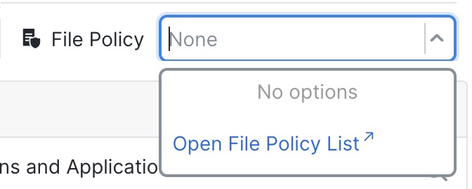
  1. Click the File Policy drop-down list and choose either an existing policy or add one by choosing the Open File Policy List.

    Figure 18. File Policy
    File Policy

    For a new policy, the Policies > Malware & File page opens in a separate tab.

  2. See the Cisco Secure Firewall Device Manager Configuration Guide for details on creating the policy.

  3. Return to the Add Rule page and select the newly created policy from the drop-down list.

Step 6

Click Apply.

The rule is added to the Rules table.

Step 7

Click Save.


Enable SSH on the Outside Interface

This section describes how to enable SSH connections to the outside interface.

By default, you can use the admin user for which you configured the password during initial setup.

Procedure


Step 1

Choose Devices > Platform Settings and create or edit the threat defense policy.

Step 2

Select SSH Access.

Step 3

Identify the outside interface and IP addresses that allow SSH connections.

  1. Click Add to add a new rule, or click Edit to edit an existing rule.

  2. Configure the rule properties:

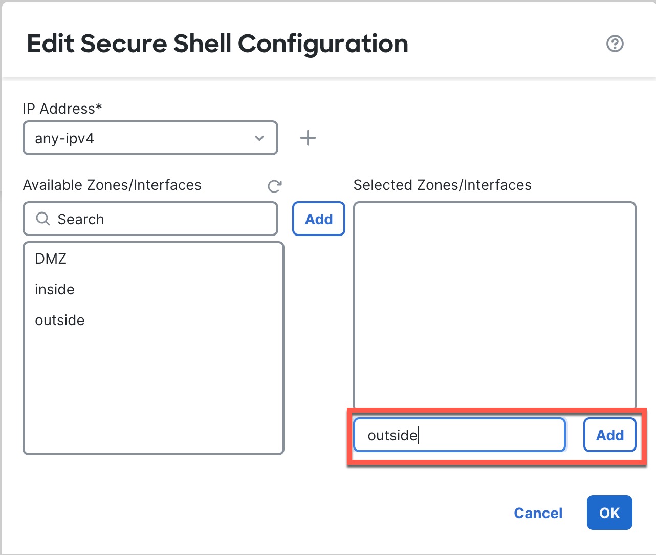
    • IP Address—The network object or group that identifies the hosts or networks you are allowing to make SSH connections. Choose an object from the drop-down menu, or click + to add a new network object.

    • Available Zones/Interfaces—Add the outside zone or type the outside interface name into the field below the Selected Zones/Interfaces list and click Add.

    Figure 19. Enable SSH on the Outside Interface
    Enable SSH on the Outside Interface
  3. Click OK.

Step 4

Click Save.

You can now go to Deploy > Deployment and deploy the policy to assigned devices. The changes are not active until you deploy them.


Deploy the Configuration

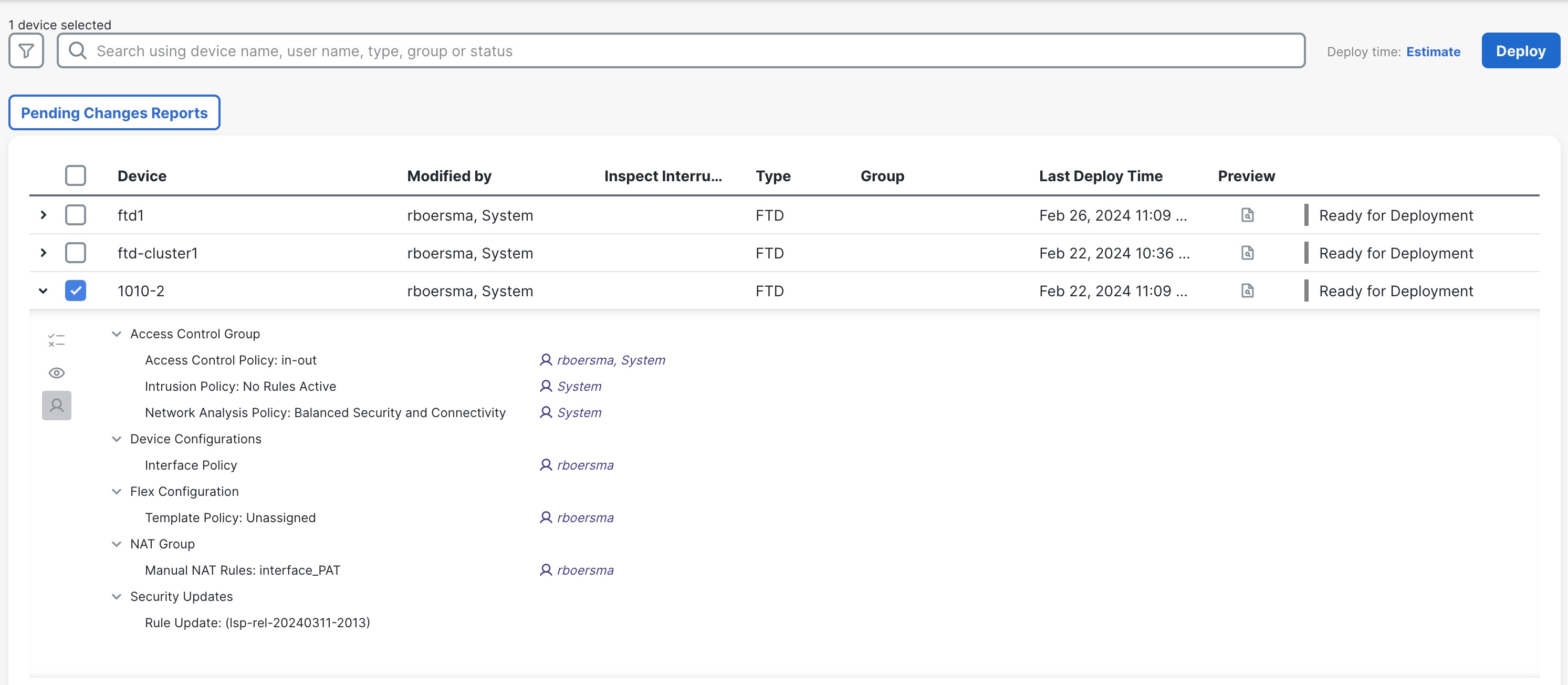
Deploy the configuration changes to the device; none of your changes are active on the device until you deploy them.

Procedure


Step 1

Click Deploy in the upper right.

Figure 20. Deploy
Deploy

Step 2

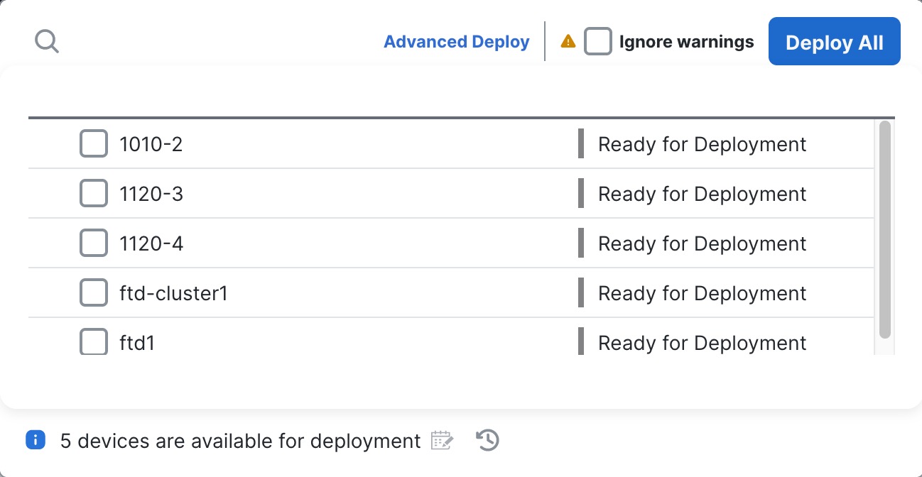
For a quick deployment, check specific devices and then click Deploy.

Figure 21. Deploy Selected
Deploy Selected

Or click Deploy All to deploy to all devices.

Figure 22. Deploy All
Deploy All

Otherwise, for additional deployment options, click Advanced Deploy.

Figure 23. Advanced Deployment
Advanced Deploy

Step 3

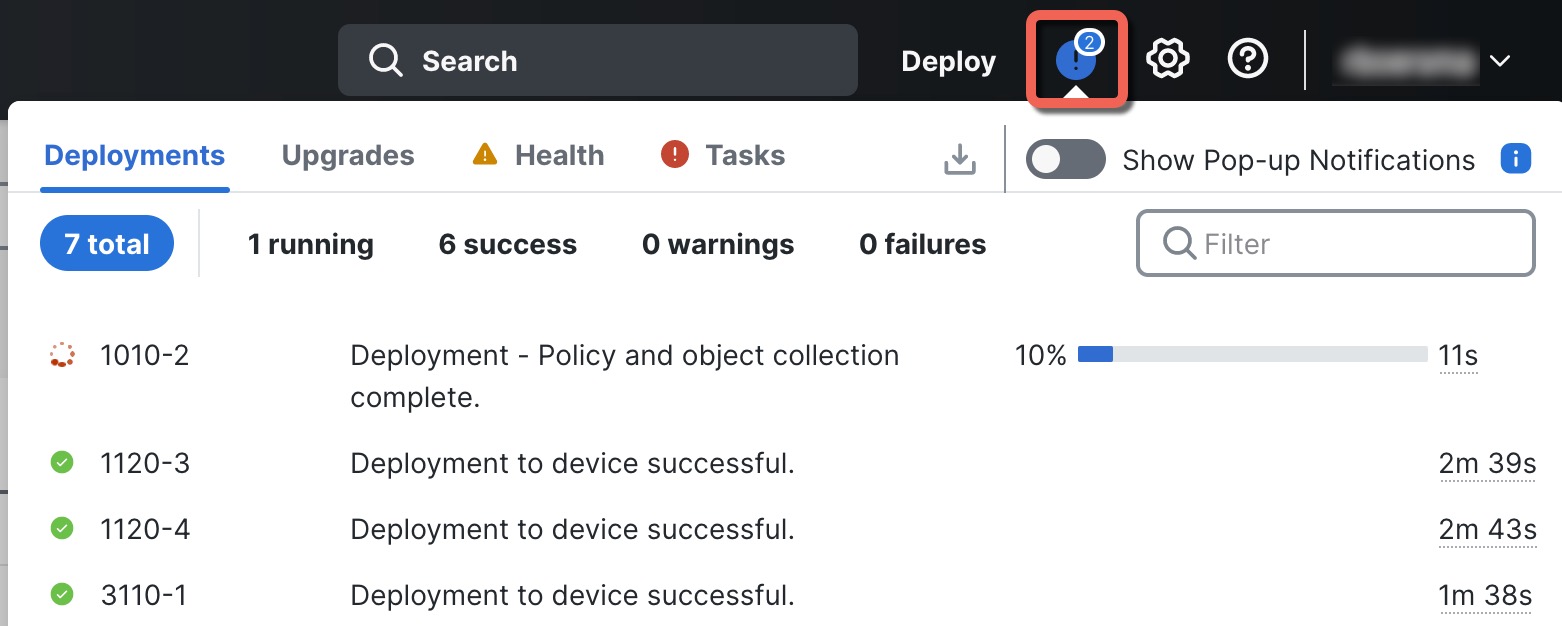
Ensure that the deployment succeeds. Click the icon to the right of the Deploy button in the menu bar to see status for deployments.

Figure 24. Deployment Status
Deployment Status