High Availability (Failover)

The following topics describe how to configure and manage active/standby failover to accomplish high availability of the FTD system.

About High Availability (Failover)

A high availability or failover setup joins two devices so that if the primary device fails, the secondary device can take over. This helps you keep your network operational in case of device failure.

Configuring high availability requires two identical FTD devices connected to each other through a dedicated failover link and, optionally, a state link. The two units constantly communicate over the failover link to determine the operating status of each unit and to synchronize deployed configuration changes. The system uses the state link to pass connection state information to the standby device, so that if a failover occurs, user connections are preserved.

The units form an active/standby pair, where one unit is the active unit and passes traffic. The standby unit does not actively pass traffic, but synchronizes configuration and other state information from the active unit.

The health of the active unit (hardware, interfaces, software, and environmental status) is monitored to determine if specific failover conditions are met. If those conditions are met, the active unit fails over to the standby unit, which then becomes active.

About Active/Standby Failover

Active/Standby failover lets you use a standby FTD device to take over the functionality of a failed unit. When the active unit fails, the standby unit becomes the active unit.

Primary/Secondary Roles and Active/Standby Status

The main differences between the two units in a failover pair are related to which unit is active and which unit is standby, namely which IP addresses to use and which unit actively passes traffic.

However, a few differences exist between the units based on which unit is primary (as specified in the configuration) and which unit is secondary:

  • The primary unit always becomes the active unit if both units start up at the same time (and are of equal operational health).

  • The primary unit MAC addresses are always coupled with the active IP addresses. The exception to this rule occurs when the secondary unit becomes active and cannot obtain the primary unit MAC addresses over the failover link. In this case, the secondary unit MAC addresses are used.

Active Unit Determination at Startup

The active unit is determined by the following:

  • If a unit boots and detects a peer already running as active, it becomes the standby unit.

  • If a unit boots and does not detect a peer, it becomes the active unit.

  • If both units boot simultaneously, then the primary unit becomes the active unit, and the secondary unit becomes the standby unit.

Failover Events

In Active/Standby failover, failover occurs on a unit basis.

The following table shows the failover action for each failure event. For each failure event, the table shows the failover policy (failover or no failover), the action taken by the active unit, the action taken by the standby unit, and any special notes about the failover condition and actions.

Table 1. Failover Events

Failure Event

Policy

Active Unit Action

Standby Unit Action

Notes

Active unit failed (power or hardware)

Failover

n/a

Become active

Mark active as failed

No hello messages are received on any monitored interface or the failover link.

Formerly active unit recovers

No failover

Become standby

No action

None.

Standby unit failed (power or hardware)

No failover

Mark standby as failed

n/a

When the standby unit is marked as failed, then the active unit does not attempt to fail over, even if the interface failure threshold is surpassed.

Failover link failed during operation

No failover

Mark failover link as failed

Mark failover link as failed

You should restore the failover link as soon as possible because the unit cannot fail over to the standby unit while the failover link is down.

Failover link failed at startup

No failover

Become active

Mark failover link as failed

Become active

Mark failover link as failed

If the failover link is down at startup, both units become active.

State link failed

No failover

No action

No action

State information becomes out of date, and sessions are terminated if a failover occurs.

Interface failure on active unit above threshold

Failover

Mark active as failed

Become active

None.

Interface failure on standby unit above threshold

No failover

No action

Mark standby as failed

When the standby unit is marked as failed, then the active unit does not attempt to fail over even if the interface failure threshold is surpassed.

Failover and Stateful Failover Links

The failover link is a dedicated connection between the two units. The stateful failover link is also a dedicated connection, but you can either use the one failover link as a combined failover/state link, or you can create a separate, dedicated state link. If you use just the failover link, the stateful information also goes over that link: you do not lose stateful failover capability.

By default, the communications on the failover and stateful failover links are plain text (unencrypted). You can encrypt the communications for enhanced security by configuring an IPsec encryption key.

The following topics explain these interfaces in more detail, and include recommendations on how to wire the devices for the best results.

Failover Link

The two units in a failover pair constantly communicate over a failover link to determine the operating status of each unit and to synchronize configuration changes.

The following information is communicated over the failover link:

  • The unit state (active or standby).

  • Hello messages (keep-alives).

  • Network link status.

  • MAC address exchange.

  • Configuration replication and synchronization.

  • System database updates, including VDB and rules, but not including the geolocation and Security Intelligence databases. Each system separately downloads geolocation and Security Intelligence updates. If you create an update schedule, these should remain synchronized. However, if you do a manual geolocation or Security Intelligence update on the active device, you should also do one on the standby device.


Note

Eventing, reporting, and audit log data are not synchronized. Event viewer and the dashboards show data related to the given unit only. In addition, deployment history, task history, and other audit log events are not synchronized.


Stateful Failover Link

The system uses the state link to pass connection state information to the standby device. This information helps the standby unit maintain existing connections when a failover occurs.

Using a single link for both the failover and stateful failover links is the best way to conserve interfaces. However, you must consider a dedicated interface for the state link and failover link, if you have a large configuration and a high traffic network.

Interfaces for the Failover and State Links

You can use an unused, but enabled, data interface (physical) as the failover link; however, you cannot specify an interface that is currently configured with a name. The failover link interface is not configured as a normal networking interface; it exists for failover communication only. This interface can only be used for the failover link (and also for the state link). You cannot use a management interface or a subinterface for failover.

The FTD device does not support sharing interfaces between user data and the failover link.

See the following guidelines for sizing the failover and state link:

  • Firepower 4100/9300—We recommend that you use a 10 GB data interface for the combined failover and state link.

  • All other models—1 GB interface is large enough for a combined failover and state link.

Connecting the Failover and Stateful Failover Interfaces

You can use any unused data physical interfaces as the failover link and optional dedicated state link. However, you cannot select an interface that is currently configured with a name, or one that has subinterfaces. The failover and stateful failover link interfaces are not configured as normal networking interfaces. They exist for failover communication only, and you cannot use them for through traffic or management access.

Because the configuration is synchronized between the devices, you must select the same port number for each end of a link. For example, GigabitEthernet1/3 on both devices for the failover link.

Connect the failover link, and the dedicated state link if used, in one of the following two ways:

  • Using a switch, with no other device on the same network segment (broadcast domain or VLAN) as the failover interfaces of the FTD device. A dedicated state link has the same requirement, but must be on a different network segment than the failover link.


    Note

    The advantage of using a switch is that if one of the unit’s interfaces goes down, it is easy to troubleshoot which interface failed. If you are using a direct cable connection, if one interface fails, the link is brought down on both peers, which makes it difficult to determine which device is at fault.


  • Using an Ethernet cable to connect the units directly, without the need for an external switch. The FTD supports Auto-MDI/MDIX on its copper Ethernet ports, so you can either use a crossover cable or a straight-through cable. If you use a straight-through cable, the interface automatically detects the cable and swaps one of the transmit/receive pairs to MDIX.

For optimum performance when using long distance failover, the latency for the state link should be less than 10 milliseconds and no more than 250 milliseconds. If latency is more than 10 milliseconds, some performance degradation occurs due to retransmission of failover messages.

Avoiding Interrupted Failover and Data Links

We recommend that failover links and data interfaces travel through different paths to decrease the chance that all interfaces fail at the same time. If the failover link is down, the FTD device can use the data interfaces to determine if a failover is required. Subsequently, the failover operation is suspended until the health of the failover link is restored.

See the following connection scenarios to design a resilient failover network.

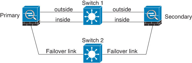
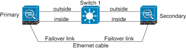
Scenario 1—Not Recommended

If a single switch or a set of switches are used to connect both failover and data interfaces between two FTD devices, then when a switch or inter-switch-link is down, both FTD devices become active. Therefore, the two connection methods shown in the following figures are not recommended.

Figure 1. Connecting with a Single Switch—Not Recommended

Connecting through a single switch. Not recommended.

Figure 2. Connecting with a Double-Switch—Not Recommended

Connecting with a double switch. Not recommended.

Scenario 2—Recommended

We recommend that failover links not use the same switch as the data interfaces. Instead, use a different switch or use a direct cable to connect the failover link, as shown in the following figures.

Figure 3. Connecting with a Different Switch

Connecting with a different switch.

Figure 4. Connecting with a Cable

Connecting with a cable.

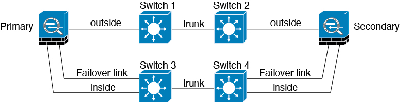
Scenario 3—Recommended

If the FTD data interfaces are connected to more than one set of switches, then a failover link can be connected to one of the switches, preferably the switch on the secure (inside) side of network, as shown in the following figure.

Figure 5. Connecting with a Secure Switch

Connecting with a secure switch.

How Stateful Failover Affects User Connections

The active unit shares connection state information with the standby unit. This means that the standby unit can maintain certain types of connections without impacting the user.

However, there are some types of connections that do not support stateful failover. For these connections, the user will need to reestablish the connection if there is a failover. Often times, this happens automatically based on the behavior of the protocol used in the connection.

The following topics explain which features are supported or not supported for stateful failover.

Supported Features

For Stateful Failover, the following state information is passed to the standby FTD device:

  • NAT translation table.

  • TCP and UDP connections and states, including HTTP connection states. Other types of IP protocols, and ICMP, are not parsed by the active unit, because they get established on the new active unit when a new packet arrives.

  • Snort connection states, inspection results, and pin hole information, including strict TCP enforcement.

  • The ARP table

  • The Layer 2 bridge table (for bridge groups)

  • The ISAKMP and IPsec SA table

  • GTP PDP connection database

  • SIP signaling sessions and pin holes.

  • Static and dynamic routing tables—Stateful Failover participates in dynamic routing protocols, like OSPF and EIGRP, so routes that are learned through dynamic routing protocols on the active unit are maintained in a Routing Information Base (RIB) table on the standby unit. Upon a failover event, packets travel normally with minimal disruption to traffic because the active secondary unit initially has rules that mirror the primary unit. Immediately after failover, the re-convergence timer starts on the newly active unit. Then the epoch number for the RIB table increments. During re-convergence, OSPF and EIGRP routes become updated with a new epoch number. Once the timer is expired, stale route entries (determined by the epoch number) are removed from the table. The RIB then contains the newest routing protocol forwarding information on the newly active unit.


    Note

    Routes are synchronized only for link-up or link-down events on an active unit. If the link goes up or down on the standby unit, dynamic routes sent from the active unit may be lost. This is normal, expected behavior.


  • DHCP Server—DHCP address leases are not replicated. However, a DHCP server configured on an interface will send a ping to make sure an address is not being used before granting the address to a DHCP client, so there is no impact to the service. State information is not relevant for DHCP relay or DDNS.

  • Access control policy decisions—Decisions related to traffic matching (including URL, URL category, geolocation, and so forth), intrusion detection, malware, and file type are preserved during failover. However, for connections being evaluated at the moment of failover, there are the following caveats:

    • AVC—App-ID verdicts are replicated, but not detection states. Proper synchronization occurs as long as the App-ID verdicts are complete and synchronized before failover occurs.

    • Intrusion detection state—Upon failover, once mid-flow pickup occurs, new inspections are completed, but old states are lost.

    • File malware blocking—The file disposition must become available before failover.

    • File type detection and blocking—The file type must be identified before failover. If failover occurs while the original active device is identifying the file, the file type is not synchronized. Even if your file policy blocks that file type, the new active device downloads the file.

  • Passive user identity decisions from the identity policy, but not those gathered through active authentication through captive portal.

  • Security Intelligence decisions.

  • RA VPN—Remote access VPN end users do not have to reauthenticate or reconnect the VPN session after a failover. However, applications operating over the VPN connection could lose packets during the failover process and not recover from the packet loss.

  • From all the connections, only established ones will be replicated on the Standby ASA.

Unsupported Features

For Stateful Failover, the following state information is not passed to the standby FTD device:

  • Sessions in plaintext tunnels such as GRE or IP-in-IP. Sessions inside tunnels are not replicated and the new active node will not be able to reuse existing inspection verdicts to match the correct policy rules.

  • Decrypted TLS/SSL connections—The decryption states are not synchronized, and if the active unit fails, then decrypted connections will be reset. New connections will need to be established to the new active unit. Connections that are not decrypted (in other words, those that match a TLS/SSL Do Not Decrypt rule action) are not affected and are replicated correctly.

  • Multicast routing.

Configuration Changes and Actions Allowed on a Standby Unit

When operating in high-availability mode, you make configuration changes to the active unit only. When you deploy the configuration, the new changes are also transmitted to the standby unit.

However, some properties are unique to the standby unit. You can change the following on a standby unit:

  • Management IP address and gateway.

  • (CLI only.) The password for the admin user account and other local user accounts. You can make this change in the CLI only, you cannot make it in the FDM. Any local user will have to change their password on both units separately.

In addition, the following actions are available on a standby device.

  • High availability actions, such as suspend, resume, reset, and break HA, and switch modes between active and standby.

  • Dashboard and eventing data are unique per device, and are not synchronized. This includes custom views in Event Viewer.

  • Audit log information is unique per device.

  • Smart Licensing registration. However, you must enable or disable the optional licenses on the active unit, and the action is synchronized with the standby unit, which requests or releases the appropriate license.

  • Backup, but not restore. You must break HA on the unit to restore a backup. If the backup includes the HA configuration, the unit will rejoin the HA group.

  • Software upgrade installation.

  • Generating troubleshooting logs.

  • Manually updating the Geolocation or Security Intelligence databases. These databases are not synchronized between the units. If you create an update schedule, the units can independently maintain consistency.

  • You can view active the FDM user sessions, and delete sessions, from the Monitoring > Sessions page.

System Requirements for High Availability

The following topics explain the requirements you must meet before incorporating two devices in a high availability configuration.

Hardware Requirements for HA

To link two devices together in a high availability configuration, you must meet the following hardware requirements.

  • The devices must be the exact same hardware model.

  • The devices must have the same number and type of interfaces.

  • The devices must have the same modules installed. For example, if one has an optional network interface module, then you must install the same module in the other device.

Software Requirements for HA

To link two devices together in a high availability configuration, you must meet the following software requirements.

  • The devices must run the exact same software version, which means the same major (first), minor (second), and maintenance (third) numbers. You can find the version in the FDM on the Devices page, or you can use the show version command in the CLI. Devices with different versions are allowed to join, but the configuration is not imported into the standby unit and failover is not functional until you upgrade the units to the same software version.

  • Both devices must be in local manager mode, that is, configured using the FDM. If you can log into the FDM on both systems, they are in local manager mode. You can also use the show managers command in the CLI to verify.

  • You must complete the initial setup wizard for each device.

  • Each device must have its own management IP address. The configuration for the management interface is not synchronized between the devices.

  • The devices must have the same NTP configuration.

  • You cannot configure any interface to obtain its address using DHCP. That is, all interfaces must have static IP addresses.

  • Both devices must have the same registration status with Cisco Defense Orchestrator: either both registered, or neither registered.

  • For the following cloud services, either both the primary and secondary device must be enabled, or the primary can be disabled while the secondary is enabled (the secondary will be disabled after HA join).

    • Cisco Success Network

    • Cisco Threat Response

  • You must deploy any pending changes before you configure high availability.

License Requirements for HA

Before configuring high availability, the units must be in the same state: either both registered with the Base license, or both in evaluation mode. If the devices are registered, they can be registered to different Cisco Smart Software Manager accounts, but the accounts must have the same state for the export-controlled functionality setting, either both enabled or both disabled. However, it does not matter if you have enabled different optional licenses on the units.

During operation, the units in the high availability pair must have the same licenses. Any license changes you make on the active unit are repeated on the standby unit during deployment.

High availability configurations require two Smart License entitlements; one for each device in the pair. You must ensure there are sufficient licenses in your account to apply to each device. It is possible to be in compliance on one device, but out of compliance on the other, if there are insufficient licenses.

For example, if the active device has the Base license and the Threat, and the standby device has only the Base license, the standby unit communicates with the Cisco Smart Software Manager to obtain an available Threat from your account. If your Smart Licenses account does not include enough purchased entitlements, your account becomes Out-of-Compliance (and the standby device is Out-of-Compliance even though the active device is compliant) until you purchase the correct number of licenses.


Note

If you register the devices to accounts that have different settings for export controlled features, or try to create an HA pair with one unit registered and the other in evaluation mode, the HA join might fail. If you configure an IPsec encryption key with inconsistent settings for export controlled features, both devices will become active after you activate HA. This will impact routing on the supported network segments, and you will have to manually break HA on the secondary unit to recover.


Guidelines for High Availability

Additional Guidelines

  • 169.254.0.0/16 and fd00:0:0:*::/64 are internally used subnets and you cannot use them for the failover or state links.

  • The configuration from the active unit is synchronized to the standby unit when you run a deployment job on the active unit. However, some changes do not show up in the pending changes even though they are not synchronized on the standby unit until you deploy changes. If you alter any of the following, the changes are hidden and you must run a deployment job before they are configured on the standby unit. If you need to apply the change immediately, you will need to make some other change that does appear in the pending changes. Hidden changes include edits to the following: schedules for rule, geodatabase, Security Intelligence, or VDB updates; schedules for backups; NTP; DNS for the management interface; license entitlement; cloud services options; URL filtering options.

  • You should do backups on both the primary and secondary units. To restore a backup, you must first break HA. Do not restore the same backup on both units, because they would then both go active. Instead, restore the backup on the unit you want to go active first, then restore the equivalent backup on the other unit.

  • The Test button for the various identity sources works on the active unit only. If you need to test identity source connectivity for the standby device, you must first switch modes to make the standby peer the active peer.

  • Creating or breaking the high availability configuration restarts the Snort inspection process on both devices when the configuration change is deployed. This can result in through traffic disruption until the process completely restarts.

  • When you initially configure high availability, if the Security Intelligence and Geolocation database versions on the secondary are different than they are on the primary, jobs to update the databases are scheduled on the secondary unit. These jobs are run on the next deployment from the active unit. Even if the HA join fails, these jobs remain and will execute on the next deployment.

  • You might be prevented from logging into the standby unit if you are authenticated against an external identity source (that is, you are not the local admin user). You must log into the active unit at least once and deploy the configuration before you are allowed to log into the standby unit. This restriction does not apply to the local admin user.

  • When the active unit fails over to the standby unit, the connected switch port running Spanning Tree Protocol (STP) can go into a blocking state for 30 to 50 seconds when it senses the topology change. To avoid traffic loss while the port is in a blocking state, you can enable the STP PortFast feature on the switch:

    interface interface_id spanning-tree portfast

    This workaround applies to switches connected to both routed mode and bridge group interfaces. The PortFast feature immediately transitions the port into STP forwarding mode upon linkup. The port still participates in STP. So if the port is to be a part of the loop, the port eventually transitions into STP blocking mode.

  • Configuring port security on the switches connected to the high availability pair can cause communication problems when a failover event occurs. This problem occurs because when a secure MAC address configured or learned on one secure port moves to another secure port, a violation is flagged by the switch port security feature.

  • For Active/Standby high availability and a VPN IPsec tunnel, you cannot monitor both the active and standby units using SNMP over the VPN tunnel. The standby unit does not have an active VPN tunnel, and will drop traffic destined for the network management system (NMS). You can instead use SNMPv3 with encryption so the IPsec tunnel is not required.

Configuring High Availability

Use a high availability setup to ensure network connectivity even if a device fails. With active/standby high availability, two devices are linked, so that if the active device fails, the standby device takes over and users should see no more than a brief connectivity problem.

The following procedure explains the end-to-end process for setting up an active/standby high availability (HA) pair.

Procedure


Step 1

Prepare the Two Units for High Availability.

Step 2

Configure the Primary Unit for High Availability.

Step 3

Configure the Secondary Unit for High Availability.

Step 4

Configure Failover Criteria for Health Monitoring.

The criteria includes peer monitoring and interface monitoring. Although all failover criteria have default settings, you should at least examine them to verify that the default settings work for your network.

Step 5

(Optional but recommended.) Configure Standby IP and MAC Addresses.

Step 6

(Optional.) Verify the High Availability Configuration.


Prepare the Two Units for High Availability

There are many things that you must prepare correctly before you can successfully configure high availability.

Procedure


Step 1

Ensure that the devices meet the requirements explained in Hardware Requirements for HA.

Step 2

Determine whether you will use a single failover link, or separate failover and stateful failover links, and identify the ports you will use.

You must use the same port number on each device for each link. For example, GigabitEthernet 1/3 on both devices for the failover link. Know which ones you will use so that you do not accidentally use them for other purposes. For more information, see Failover and Stateful Failover Links.

Step 3

Install the devices, connect them to the network, and complete the initial setup wizard on each device.

  1. Review the recommended network designs in Avoiding Interrupted Failover and Data Links.

  2. Connect at least the outside interfaces, as explained in Connect the Interfaces.

    You can also connect the other interfaces, but you must ensure that you use the same port on each device to connect to a given subnet. Because the devices will share the same configuration, you must connect them to your networks in a parallel manner.

    Note 

    The setup wizard does not let you change the IP addresses on the management and inside interface. Thus, if you connect either of these interfaces on the primary device to the network, do not also connect the interfaces on the secondary device, or you will get an IP address conflict. You can directly connect your workstation to one of these interfaces and get an address through DHCP, so that you can connect to the FDM and configure the device.

  3. Complete the initial setup wizard on each device. Ensure that you specify static IP addresses for the outside interface. In addition, configure the same NTP servers. For more information, see Complete the Initial Configuration Using the Setup Wizard.

    Choose the same licensing and Cisco Success Network options for the units. For example, evaluation mode for each or register the devices.

  4. On the secondary device, select Device > System Settings > Management Interface and configure a unique IP address, change the gateway if necessary, and disable or change the DHCP server settings to suit your needs.

  5. On the secondary device, select Device > Interface and edit the inside interface. Either delete the IP address, or change it. Also, delete the DHCP server defined for the interface, because you cannot have two DHCP servers on the same network.

  6. Deploy the configuration on the secondary device.

  7. If necessary based on your network topology, log into the primary device and change the management address, gateway, and DHCP server settings, and the inside interface IP address and DHCP server settings. Deploy the configuration if you make any changes.

  8. If you have not connected the inside interface, or management interface if you use a separate management network, you can now connect them to the switches.

Step 4

Verify that the devices have the exact same software version, which means the same major (first), minor (second), and maintenance (third) numbers. You can find the version in the FDM on the Devices page, or you can use the show version command in the CLI.

If they are not running the same software versions, obtain the preferred software version from Cisco.com and install it on each device. For details, see Upgrading FTD Software.

Step 5

Connect and configure the failover and stateful failover links.

  1. Following your preferred network design (chosen from Avoiding Interrupted Failover and Data Links), connect the failover interfaces for each device appropriately, either to a switch or directly to each other.

  2. If you are using a separate state link, also connect the stateful failover interfaces for each device appropriately.

  3. Log into each device in turn and go to Device > Interface. Edit each interface and verify there are no interface names or IP addresses configured.

    If the interfaces are configured with names, you might need to remove them from security zones and delete other configurations before you can delete the name. If deleting the name fails, examine the error messages to determine what other changes you need to make.

Step 6

On the primary device, connect the remaining data interfaces and configure the device.

  1. Select Device > Interface, edit each interface used for through traffic and configure the primary static IP addresses.

  2. Add the interfaces to security zones, and configure the basic policies needed to handle traffic on the connected networks. For example configurations, see the topics listed in Best Practices: Use Cases for FTD.

  3. Deploy the configuration.

Step 7

Verify that you meet all the requirements explained in Software Requirements for HA.

Step 8

Verify that you have consistent licensing (registered or in evaluation mode). For more information, see License Requirements for HA.

Step 9

On the secondary device, connect the remaining data interfaces to the same networks as the equivalent interfaces on the primary device. Do not configure the interfaces.

Step 10

On each device, select Device > System Settings > Cloud Services and verify that you have the same settings.

You are now ready to configure high availability on the primary device.


Configure the Primary Unit for High Availability

To set up an active/standby high availability pair, you must first configure the primary device. The primary device is the unit that you intend should be active under normal circumstances. The secondary device remains in standby mode until the primary unit becomes unavailable.

Select which device you want to be primary, then log into the FDM on that device and follow this procedure.


Note

Once you establish the high availability pair, you must break the pair in order to edit the configuration described in this procedure.


Before you begin

Ensure that the interfaces you will configure for the failover and stateful failover link are not named. If they currently are named, you must remove the interfaces from any policies that use them, including security zone objects, then edit the interfaces to delete the name. The interfaces must also be in routed mode, not passive mode. These interfaces must be dedicated for use in the HA configuration: you cannot use them for any other purposes.

If there are any pending changes, you must deploy them before you can configure HA.

Procedure


Step 1

Click Device.

Step 2

On the right side of the device summary, click Configure next to the High Availability group.

If you are configuring HA for the first time on the device, the group would look like the following.


High Availability group before HA is configured.
Step 3

On the High Availability page, click the Primary Device box.

If the secondary device is already configured, and you copied the configuration to the clipboard, you can click the Paste from Clipboard button and paste in the configuration. This will update the fields with the appropriate values, which you can then verify.

Step 4

Configure the Failover Link properties.

The two units in a failover pair constantly communicate over a failover link to determine the operating status of each unit and to synchronize configuration changes. For more information, see Failover Link.

  • Physical Interface—Select the interface you connected to the secondary device for use as the failover link. This must be an unnamed interface.

  • Type—Select whether you will use an IPv4 or IPv6 address for the interface. You can configure one type of address only.

  • Primary IP—Enter the IP address for the interface on this device. For example, 192.168.10.1. For IPv6 addresses, you must include the prefix length in standard notation, for example, 2001:a0a:b00::a0a:b70/64.

  • Secondary IP—Enter the IP address that should be configured on the other end of the link for the interface on the secondary device. The address must be on the same subnet as the primary address, and it must be different than the primary address. For example, 192.168.10.2 or 2001:a0a:b00::a0a:b71/64.

  • Netmask (IPv4 only)—Enter the subnet mask for the primary/secondary IP address.

Step 5

Configure the Stateful Failover Link properties.

The system uses the state link to pass connection state information to the standby device. This information helps the standby unit maintain existing connections when a failover occurs. You can either use the same link as the failover link, or configure a separate link.

  • Use the Same Interface as the Failover Link—Select this option if you want to use a single link for the failover and stateful failover communications. If you select this option, continue with the next step.

  • Physical Interface—If you want to use a separate stateful failover link, select the interface you connected to the secondary device for use as the stateful failover link. This must be an unnamed interface. Then, configure the following properties:

    • Type—Select whether you will use an IPv4 or IPv6 address for the interface. You can configure one type of address only.

    • Primary IP—Enter the IP address for the interface on this device. The address must be on a different subnet than the one used for the failover link. For example, 192.168.11.1. For IPv6 addresses, you must include the prefix length in standard notation, for example, 2001:a0a:b00:a::a0a:b70/64.

    • Secondary IP—Enter the IP address that should be configured on the other end of the link for the interface on the secondary device. The address must be on the same subnet as the primary address, and it must be different than the primary address. For example, 192.168.11.2 or 2001:a0a:b00:a::a0a:b71/64.

    • Netmask (IPv4 only)—Enter the subnet mask for the primary/secondary IP address.

Step 6

(Optional.) Enter an IPsec Encryption Key string if you want to encrypt communication between the two units in the pair.

You must configure the exact same key on the secondary node, so make a note of the string you enter.

If you do not enter a key, all communication on the failover and stateful failover links is in plain text. If you are not using direct cable connections between the interfaces, this could be a security problem.

Note 

If you configure HA failover encryption in evaluation mode, the systems use DES for the encryption. If you then register the devices using an export-compliant account, the devices will use AES after a reboot. Thus, if a system reboots for any reason, including after installing an upgrade, the peers will be unable to communicate and both units will become the active unit. We recommend that you do not configure encryption until after you register the devices. If you do configure this in evaluation mode, we recommend you remove the encryption before registering the devices.

Step 7

Click Activate HA.

The system immediately deploys the configuration to the device. You do not need to start a deployment job. If you do not see a message saying that your configuration was saved and deployment is in progress, scroll to the top of the page to see the error messages.

The configuration is also copied to the clipboard. You can use the copy to quickly configure the secondary unit. For added security, the encryption key is not included in the clipboard copy.

After configuration completes, you get a message explaining the next steps you need to take. Click Got It after reading the information.

At this point, you should be on the High Availability page, and your device status should be “Negotiating.” The status should transition to Active even before you configure the peer, which should appear as Failed until you configure it.


HA status after configuring the primary, before configuring the secondary.

You can now configure the secondary unit. See Configure the Secondary Unit for High Availability.

Note 

The selected interfaces are not configured directly. However, if you enter show interface in the CLI, you will see that the interfaces are using the specified IP addresses. The interfaces are named “failover-link” and if you configure a separate state link, “stateful-failover-link.”


Configure the Secondary Unit for High Availability

After you configure the primary device for active/standby high availability, you must then configure the secondary device. Log into the FDM on that device and follow this procedure.


Note

If you have not done so already, copy the high availability configuration from the primary device to the clipboard. It is much easier to configure the secondary device using copy/paste than to manually enter the data.


Procedure


Step 1

Click Device.

Step 2

On the right side of the device summary, click Configure next to the High Availability group.

If you are configuring HA for the first time on the device, the group would look like the following.


High Availability group before HA is configured.
Step 3

On the High Availability page, click the Secondary Device box.

Step 4

Do one of the following:

  • Easy method—Click the Paste from Clipboard button, paste in the configuration and click OK. This will update the fields with the appropriate values, which you can then verify.

  • Manual method—Configure the failover and stateful failover links directly. Enter the exact same settings on the secondary device that you entered on the primary device.

Step 5

If you configured an IPSec Encryption Key on the primary device, enter the exact same key for the secondary device.

Step 6

Click Activate HA.

The system immediately deploys the configuration to the device. You do not need to start a deployment job. If you do not see a message saying that your configuration was saved and deployment is in progress, scroll to the top of the page to see the error messages.

After configuration completes, you get a message saying that you have configured HA. Click Got It to dismiss the message.

At this point, you should be on the High Availability page, and your device status should indicate that this is the secondary device. If the join with the primary device was successful, the device will synchronize with the primary, and eventually the mode should be Standby and the peer should be Active.


HA status after configuring secondary unit, when the HA join is successful.

Note 

The selected interfaces are not configured directly. However, if you enter show interface in the CLI, you will see that the interfaces are using the specified IP addresses. The interfaces are named “failover-link” and if you configure a separate state link, “stateful-failover-link.”


Configure Failover Criteria for Health Monitoring

The units in a high availability configuration monitor themselves for overall health and for interface health.

The failover criteria define the health monitoring metrics that determine whether a peer has failed. If the active peer is the unit that violates the criteria, then it triggers a failover to the standby unit. If the standby peer is the unit that violates the criteria, it is marked as failed and is not available for failover.

You can configure failover criteria on the active device only.

The following table shows the failover triggering events and associated failure detection timing.

Table 2. Failover Times Based on Failover Criteria

Failover Triggering Event

Minimum

Default

Maximum

The active unit loses power or stops normal operation.

800 milliseconds

15 seconds

45 seconds

An active unit interface physical link is down.

500 milliseconds

5 seconds

15 seconds

An active unit interface is up, but a connection problem causes interface testing.

5 seconds

25 seconds

75 seconds

The following topics explain how to customize the failover health monitoring criteria and also how the system tests interfaces.

Configure Peer Unit Health Monitoring Failover Criteria

Each peer in a high availability configuration determines the health of the other unit by monitoring the failover link with hello messages. When a unit does not receive three consecutive hello messages on the failover link, the unit sends LANTEST messages on each data interface, including the failover link, to validate whether the peer is responsive. The action that the device takes depends on the response from the other unit:

  • If the device receives a response on the failover link, then it does not fail over.

  • If the device does not receive a response on the failover link, but it does receive a response on a data interface, then the unit does not fail over. The failover link is marked as failed. You should restore the failover link as soon as possible because the unit cannot fail over to the standby while the failover link is down.

  • If the device does not receive a response on any interface, then the standby unit switches to active mode and classifies the other unit as failed.

You can configure the poll and hold time for the hello messages.

Procedure

Step 1

On the active device, click Device.

Step 2

Click the High Availability link on the right side of the device summary.

The Failover Criteria are listed in the right column of the High Availability page.

Step 3

Define the Peer Timing Configuration.

These settings determine how quickly the active device can fail over to the standby device. With a faster poll time, the device can detect failure and trigger failover faster. However, faster detection can cause unnecessary switchovers when the network is temporarily congested. The default settings are appropriate for most situations.

If a unit does not hear hello packet on the failover interface for one polling period, additional testing occurs through the remaining interfaces. If there is still no response from the peer unit during the hold time, the unit is considered failed and, if the failed unit is the active unit, the standby unit takes over as the active unit.

  • Poll Time—The amount of time between hello messages. Enter 1 - 15 seconds, or 200 - 999 milliseconds. The default is 1 second.

  • Hold Time—The time during which a unit must receive a hello message on the failover link, after which the peer unit is declared failed. The hold time must be at least 3 times more than the poll time. Enter 1 - 45 seconds, or 800 - 999 milliseconds. The default is 15 seconds.

Step 4

Click Save.


Configure Interface Health Monitoring Failover Criteria

You can monitor up to 211 interfaces, depending on your device model. You should monitor important interfaces. For example, interfaces that ensure throughput between important networks. Monitor an interface only if you configure standby IP addresses for it, and if the interface should be always up.

When a unit does not receive hello messages on a monitored interface for 2 polling periods, it runs interface tests. If all interface tests fail for an interface, but this same interface on the other unit continues to successfully pass traffic, then the interface is considered to be failed. If the threshold for failed interfaces is met, then a failover occurs. If the other unit's interface also fails all the network tests, then both interfaces go into the “Unknown” state and do not count towards the failover limit.

An interface becomes operational again if it receives any traffic. A failed device returns to standby mode if the interface failure threshold is no longer met.

You can monitor interface HA status from the CLI or CLI Console using the show monitor-interface command. For more information, see Monitoring Status for HA-Monitored Interfaces.


Note

When an interface goes down, for failover it is still considered to be a unit issue. If the unit detects that an interface is down, failover occurs immediately (if you keep the default threshold of 1 interface), without waiting for the interface holdtime. The interface holdtime is only useful when the unit considers its status to be OK, although it is not receiving hello packets from the peer.


Before you begin

By default, all named physical interfaces are selected for HA monitoring. Thus, you should disable monitoring on unimportant physical interfaces. For subinterfaces or bridge groups, you must manually enable monitoring.

To disable interface monitoring completely and prevent failover due to interface failure, simply ensure that no interface is enabled for HA monitoring.

Procedure

Step 1

On the active device, click Device.

Step 2

Click the High Availability link on the right side of the device summary.

The Failover Criteria are listed in the right column of the High Availability page.

Step 3

Define the Interface Failure Threshold.

If the number of failed interfaces meets the threshold, the unit marks itself as failed. If the unit is the active unit, it fails over to the standby unit. If the unit is the standby unit, by marking itself as failed, the active unit will not consider the unit as available for failover.

When setting this criteria, consider how many interfaces you are monitoring. For example, if you enable monitoring on only 2 interfaces, then a threshold of 10 interfaces will never be reached. You configure monitoring for an interface by selecting the Enable for HA Monitoring option on the Advanced Options tab when editing interface properties.

By default, the unit marks itself as failed if one monitored interface fails.

You can set the interface failure threshold by selecting one of the following Failover Criteria options:

  • Number of failed interfaces exceeds—Enter the raw number of interfaces. The default is 1. The maximum actually depends on the device model and can vary, but you cannot enter more than 211. If you use this criteria, you will get a deployment error if you enter a number larger than the device supports. Try a smaller number or use percentage instead.

  • Percentage of failed interfaces exceeds—Enter a number from 1 - 100. For example, if you enter 50%, and you are monitoring 10 interfaces, then the device marks itself as failed if 5 interfaces fail.

Step 4

Define the Interface Timing Configuration.

These settings determine how quickly the active device can determine if an interface has failed. With a faster poll time, the device can detect interface failure faster. However, faster detection can mean that busy interfaces get marked as failed when in fact they are healthy, which can result in unnecessarily frequent failovers. The default settings are appropriate for most situations.

If an interface link is down, interface testing is not conducted and the standby unit could become active in just one interface polling period if the number of failed interfaces meets or exceeds the configured interface failover threshold.

  • Poll Time—The frequency that hello packets are sent out on data interfaces. Enter 1 - 15 seconds, or 500 - 999 milliseconds. The default is 5 seconds.

  • Hold Time—The hold time determines how long it takes from the time a hello packet is missed to when the interface is marked as failed. Enter 5 - 75 seconds. You cannot enter a hold time that is less than 5 times the poll time.

Step 5

Click Save.

Step 6

Enable HA monitoring for each interface you want to monitor.

  1. Choose Device > Interfaces.

    If an interface is being monitored, the Monitor for HA column indicates Enabled.

  2. Click the edit icon (edit icon) for an interface whose monitoring status you want to change.

    You cannot edit the failover or stateful failover interfaces. Interface monitoring does not apply to them.

  3. Click the Advanced Options tab.

  4. Select or deselect the Enable for HA Monitoring checkbox as preferred.

  5. Click OK.

Step 7

(Optional, but recommended.) Configure standby IP addresses and MAC addresses for monitored interfaces. See Configure Standby IP and MAC Addresses.


How the System Tests Interface Health

The system continuously tests interfaces that you are monitoring for high availability health. The address used for testing an interface is based on the address types you configure:

  • If an interface has both IPv4 and IPv6 addresses configured on it, the device uses the IPv4 addresses to perform the health monitoring.

  • If an interface has only IPv6 addresses configured on it, then the device uses IPv6 neighbor discovery instead of ARP to perform the health monitoring tests. For the broadcast ping test, the device uses the IPv6 all nodes address (FE02::1).

The system performs the following tests on each unit:

  1. Link Up/Down test—A test of the interface status. If the Link Up/Down test indicates that the interface is down, then the unit considers it failed. If the status is Up, then the unit performs the Network Activity test.

  2. Network Activity test—A received network activity test. The purpose of this test is to generate network traffic using LANTEST messages to determine which (if either) unit has failed. At the start of the test, each unit clears its received packet count for its interfaces. As soon as a unit receives any packets during the test (up to 5 seconds), then the interface is considered operational. If one unit receives traffic and the other unit does not, then the unit that received no traffic is considered failed. If neither unit received traffic, then the unit starts the ARP test.

  3. ARP test—A reading of the unit ARP cache for the 2 most recently acquired entries. One at a time, the unit sends ARP requests to these devices, attempting to stimulate network traffic. After each request, the unit counts all received traffic for up to 5 seconds. If traffic is received, the interface is considered operational. If no traffic is received, an ARP request is sent to the next device. If at the end of the list no traffic has been received, the unit starts the ping test.

  4. Broadcast Ping test—A ping test that consists of sending out a broadcast ping request. The unit then counts all received packets for up to 5 seconds. If any packets are received at any time during this interval, the interface is considered operational and testing stops. If no traffic is received, the testing starts over again with the ARP test.

Configure Standby IP and MAC Addresses

When you configure your interfaces, you can specify an active IP address and a standby IP address on the same network. Although recommended, the standby address is not required. Without a standby IP address, the active unit cannot perform network tests to check the standby interface health; it can only track the link state. You also cannot connect to the standby unit on that interface for management purposes.

  1. When the primary unit fails over, the secondary unit assumes the IP addresses and MAC addresses of the primary unit and begins passing traffic.

  2. The unit that is now in standby state takes over the standby IP addresses and MAC addresses.

Because network devices see no change in the MAC to IP address pairing, no ARP entries change or time out anywhere on the network.

If the secondary unit boots without detecting the primary unit, the secondary unit becomes the active unit and uses its own MAC addresses, because it does not know the primary unit MAC addresses. However, when the primary unit becomes available, the secondary (active) unit changes the MAC addresses to those of the primary unit, which can cause an interruption in your network traffic. Similarly, if you swap out the primary unit with new hardware, a new MAC address is used.

Virtual MAC addresses guard against this disruption because the active MAC addresses are known to the secondary unit at startup, and remain the same in the case of new primary unit hardware. You can manually configure virtual MAC addresses.

If you do not configure virtual MAC addresses, you might need to clear the ARP tables on connected routers to restore traffic flow. The FTD device does not send gratuitous ARPs for static NAT addresses when the MAC address changes, so connected routers do not learn of the MAC address change for these addresses.

Procedure


Step 1

Choose Device > Interfaces.

You should at least configure standby IP and MAC addresses for the interfaces you are monitoring for HA. If an interface is being monitored, the Monitor for HA column indicates Enabled.

Step 2

Click the edit icon (edit icon) for the interface whose standby addresses you want to configure.

You cannot edit the failover or stateful failover interfaces. You set the IP addresses for these interfaces when you configure high availability.

Step 3

Configure the Standby IP addresses on the IPv4 Address and IPv6 Address tabs.

The standby address is used by this interface on the standby device. If you do not set the standby IP address, the active unit cannot monitor the standby interface using network tests; it can only track the link state. Configure standby addresses for each IP version you are using.

Step 4

Click the Advance Options tab and configure the MAC Addresses.

By default, the system uses the MAC address burned into the network interface card (NIC) for the interface. Thus, all subinterfaces on an interface use the same MAC address, so you might want to create unique addresses per subinterface. Manually configured active/standby MAC addresses are also recommended if you configure high availability. Defining the MAC addresses helps maintain consistency in the network in the event of failover.

  • MAC Address—The Media Access Control address in H.H.H format, where H is a 16-bit hexadecimal digit. For example, you would enter the MAC address 00-0C-F1-42-4C-DE as 000C.F142.4CDE. The MAC address must not have the multicast bit set, that is, the second hexadecimal digit from the left cannot be an odd number.)

  • Standby MAC Address—For use with high availability. If the active unit fails over and the standby unit becomes active, the new active unit starts using the active MAC addresses to minimize network disruption, while the old active unit uses the standby address.

Step 5

Click OK.


Verify the High Availability Configuration

After completing the high availability configuration, verify that the device status indicates that both devices are operational and in active/standby mode.


High availability role and mode status.

You can verify that the high availability configuration is working by following this procedure.

Procedure


Step 1

Test that your active unit is passing traffic as expected by using FTP (for example) to send a file between hosts on different interfaces.

At least test connections from one workstation to systems that are connected to each of the configured interfaces.

Step 2

Switch modes so that the active unit is now the standby unit by doing one of the following:

  • In the FDM, select Switch Mode from the gear menu on the Device > High Availability page.

  • In the CLI of the active unit, enter no failover active .

Step 3

Repeat the connection testing to verify that you can make the same connections through the other unit in the high availability pair.

If the test is not successful, verify that you connected the unit’s interfaces to the same networks as the equivalent interfaces on the other unit.

You can see the HA status from the High Availability page. You can also use the CLI or CLI Console of the unit, and enter the show failover command to check the failover status. Also, use the show interface command to verify the interface configuration for the interfaces used in any connection tests that failed.

If these actions do not identify the problem, there are other steps you can take. See Troubleshooting High Availability (Failover).

Step 4

When you are finished, you can switch modes to return active status to the original unit that was active.


Managing High Availability

You can manage a high availability pair by clicking the High Availability link on the Device Summary page.


High availability group, device summary page.

The High Availability page includes the following:

  • Role and Mode Status—The left status area shows whether the device is the Primary or Secondary device in the group. The mode indicates whether this device is active or standby, or whether HA has been suspended or the device is waiting to join the peer device. It also shows the status of the peer device, which can be active, standby, suspended, or failed. For example, when you are logged into the primary device and it is also the active device, and the secondary device is healthy and ready for failover if needed, the status would look like the following. You can click the icon between the peers to get information on the configuration synchronization status between the devices.


    High availability role and mode status.

  • Failover History link—Click this link to see the detailed history of status of the devices in the pair. The system opens the CLI Console and executes the show failover history details command.

  • Deployment History link—Click this link to go to the audit log with the events filtered to show deployment jobs only.

  • Gear button Gear/Settings button.—Click this button to perform actions on the devices.

    • Suspend HA/Resume HA—Suspending HA stops the devices from functioning as a high availability pair without removing the HA configuration. You can subsequently resume, that is, re-enable, HA on the devices. For details, see Suspending or Resuming High Availability.

    • Break HA—Breaking HA removes the high availability configuration from both devices and returns them to standalone devices. For details, see Breaking High Availability.

    • Switch Mode—Switching mode lets you force an active device to become standby, or a standby device to become active, depending from which device you perform the action. For details, see Switching the Active and Standby Peers (Forcing Failover).

  • High Availability Configuration—This panel shows the configuration of the failover pair. Click the Copy to Clipboard button to load the information into the clipboard, from where you can paste it into the secondary device’s configuration. You can also copy it into another file for your records. This information does not show whether you defined an IPsec encryption key.


    Note

    The interface configuration for HA is not reflected on the Interfaces page (Device > Interfaces). You cannot edit the interfaces that you use in an HA configuration.


  • Failover Criteria—This panel includes the settings that determine the health criteria used when evaluating whether the active unit has failed and the standby unit should become the active unit. Adjust these criteria so that you get the failover performance required in your network. For details, see Configure Failover Criteria for Health Monitoring.

The following topics explain various management tasks related to a high availability configuration.

Suspending or Resuming High Availability

You can suspend a unit in a high availability pair. This is useful when:

  • Both units are in an active-active situation and fixing the communication on the failover link does not correct the problem.

  • You want to troubleshoot an active or standby unit and do not want the units to fail over during that time.

  • You want to prevent failover while installing a software upgrade on the standby device.

When you suspend high availability, you stop the pair of devices from behaving as a failover unit. The currently active device remains active, handling all user connections. However, failover criteria are no longer monitored, and the system will never fail over to the now pseudo-standby device. The standby device will retain its configuration, but it will remain inactive.

The key difference between suspending HA and breaking HA is that on a suspended HA device, the high availability configuration is retained. When you break HA, the configuration is erased. Thus, you have the option to resume HA on a suspended system, which enables the existing configuration and makes the two devices function as a failover pair again.

If you suspend high availability from the active unit, the configuration is suspended on both the active and standby unit. If you suspend it from the standby unit, it is suspended on the standby unit only, but the active unit will not attempt to fail over to a suspended unit.

You can resume a unit only if it is in Suspended state. The unit will negotiate active/standby status with the peer unit.


Note

If necessary, you can suspend HA from the CLI by entering the configure high-availability suspend command. To resume HA, enter configure high-availability resume .


Before you begin

If you suspend high availability through the FDM, it stays suspended until you resume it, even if you reload the unit. However, if you suspend it through the CLI, it is a temporary state, and upon reload, the unit resumes the high-availability configuration automatically and negotiates the active/standby state with the peer.

If you are suspending high availability on the standby unit, please check whether the active unit is currently running a deployment job. If you switch modes while a deployment job is in progress, the job will fail and you will lose your configuration changes.

Procedure


Step 1

Click Device.

Step 2

Click the High Availability link on the right side of the device summary.

Step 3

Choose the appropriate command from the gear icon (Gear/Settings button.).

  • Suspend HA—You are prompted to confirm the action. Read the message and click OK. The HA status should show that the device is in Suspended mode.

  • Resume HA—You are prompted to confirm the action. Read the message and click OK. The HA status should return to normal, either active or standby, after the unit negotiates with the peer.


Breaking High Availability

If you no longer want the two devices to operate as a high availability pair, you can break the HA configuration. When you break HA, each device becomes a standalone device. Their configurations are changed as follows:

  • The active device retains the full configuration as it is prior to the break, with the HA configuration removed.

  • The standby device has all interface configuration removed in addition to the HA configuration. All physical interfaces are disabled, although subinterfaces are not disabled. The management interface remains active, so you can log into the device and reconfigure it.

How the break actually affects the units depends on the state of each unit when you perform the break.

  • If the units are in a healthy active/standby state, break HA from the active unit. This will remove the HA configuration from both devices in the HA pair. If you want to break HA on the standby unit only, you must log into it and first suspend HA, then you can break HA.

  • If the standby unit is in a suspended or failed state, breaking HA from the active unit removes the HA configuration from the active unit only. You must log into the standby unit and also break HA on that unit.

  • If the peers are still negotiating HA or are synchronizing their configuration, you cannot break HA. Wait for the negotiation or synchronization to complete or time out. If you believe the systems are stuck in this state, you can suspend HA and then break HA.


Note

When using the FDM, you cannot break HA from the CLI using the configure high-availability disable command.


Before you begin

For ideal results, bring the devices into a healthy active/standby state, and perform this action from the active device.

Procedure


Step 1

Click Device.

Step 2

Click the High Availability link on the right side of the device summary.

Step 3

From the gear icon (Gear/Settings button.), choose Break HA.

Step 4

Read the confirmation message, decide whether to select the option to disable interfaces, and click OK.

You must select the option to disable interfaces if you are breaking HA from the standby unit.

The system immediately deploys your changes on both this device and the peer device (if possible). It might take a few minutes for deployment to complete on each device and for each device to become independent.


Switching the Active and Standby Peers (Forcing Failover)

You can switch the active/standby modes for a functioning high-availability pair, that is, one peer is active, the other is standby. For example, if you are installing a software upgrade, you can switch the active unit to standby so that the upgrade does not impact user traffic.

You can switch modes from either the active or standby unit, but the peer unit must be functioning from the other unit’s point of view. You cannot switch modes if any unit is suspended (you must resume HA first) or failed.


Note

If necessary, you can switch between active and standby modes from the CLI. From the standby unit, enter the failover active command. From the active unit, enter the no failover active command.


Before you begin

Before switching modes, verify that the active unit is not in the middle of a deployment job. Wait for the deployment to complete before switching modes.

If the active unit has pending undeployed changes, deploy them before switching modes. Otherwise, you will lose your changes if you run a deployment job from the new active unit.

Procedure


Step 1

Click Device.

Step 2

Click the High Availability link on the right side of the device summary.

Step 3

From the gear icon (Gear/Settings button.), choose Switch Mode.

Step 4

Read the confirmation message and click OK.

The system forces failover so that the active unit becomes standby, and the standby unit becomes the new active unit.


Preserving Undeployed Configuration Changes After Failover

When you make configuration changes to the units in a high availability pair, you edit the configuration on the active unit. You then deploy your changes, and both the active and standby unit are updated with the new configuration. It does not matter if the active unit is the primary or secondary device.

However, undeployed changes are not synchronized between the units. Any undeployed changes are available on the unit where you made those changes only.

Thus, if a failover happens when you have undeployed changes, those changes are not available on the new active unit. The changes do, however, remain in place on the unit that is now standby.

To retrieve your undeployed changes, you must switch modes to force a failover and return the other unit to active status. When you log into the newly-active unit, your undeployed changes are available, and you can deploy them. Use the Switch Modes command from the High Availability settings gear menu (Gear/Settings button.).

Please keep the following in mind:

  • If you deploy changes from the active unit while there are undeployed changes on the standby unit, the undeployed changes on the standby unit will be erased. You will not be able to retrieve them.

  • When a standby unit joins a high availability pair, any undeployed changes on the standby unit will be erased. The configuration is synchronized whenever a unit joins, or rejoins, the pair.

  • If the unit that contains the undeployed changes failed catastrophically, and you had to replace or reimage the unit, your undeployed changes are permanently lost.

Changing Licenses and Registration in High Availability Mode

The units in a high availability pair must have the same licenses and registration status. To make changes:

  • You enable or disable optional licenses on the active unit. Then, you deploy the configuration, and the standby unit requests (or frees) the necessary licenses. When enabling licenses, you must ensure that your Cisco Smart Software Manager account has sufficient licenses available, or you could have one unit compliant while the other unit is non-compliant.

  • You register, or unregister, the units separately. To function correctly, the units must both be in evaluation mode, or both be registered. You can register the units to different Cisco Smart Software Manager accounts, but the accounts must have the same state for the export-controlled functionality setting, either both enabled or both disabled. You cannot deploy configuration changes if the units have inconsistent registration status.

Editing the HA IPsec Encryption Key or HA Configuration

You can change any of the failover criteria by logging into the active unit, making your changes, and deploying them.

However, if you need to change the IPsec encryption key used on your failover links, or change the interfaces or IP addresses for either the failover or stateful failover links, you must first break the HA configuration. You can then reconfigure the primary and secondary units with the new encryption key or failover/stateful failover link settings.

Marking a Failed Unit Healthy

A unit in a high availability configuration can be marked as failed due to regular health monitoring. If the unit is healthy, it should return to normal status when it meets health monitoring requirements again. If you see a healthy device failing frequently, you might want to increase the peer timeouts, stop monitoring specific interfaces that are less important, or change interface monitoring timeouts.

You can force a failed unit to be seen as healthy by entering the failover reset command from the CLI. We recommend that you enter the command from the active unit, which will reset the status of the standby unit. You can display the failover status of the unit with the show failover or show failover state commands.

Restoring a failed unit to an unfailed state does not automatically make it active. Restored units remain in the standby state until made active by failover (forced or natural).

Resetting the device status does not resolve the problems that led to the device being marked failed. If you do not address the problems, or relax your monitoring timeouts, the device can be marked as failed again.

Installing Software Upgrades on HA Devices

You can upgrade the system software running on the devices in a high availability pair without disrupting traffic in your network. Basically, you upgrade the standby device, so that the active device continues handling traffic. After the upgrade completes, you switch roles and again upgrade the standby unit.

If you also need to update the FXOS version on the chassis, install the FXOS upgrades on each device before installing using the following procedure. Use the same technique: install the FXOS upgrade on the standby device, switch roles to make the standby active, then install the upgrade on the new (down-level) standby device.

While the units in the high availability group are running different software versions, failover is not possible. Under normal circumstances, the units must be running the same software version. The only time it is valid to have them running different versions is when you are in the process of installing software upgrades.

This procedure summarizes the upgrade process. For detailed information, see Upgrading FTD Software.


Note

During the upgrade, the system suspends HA while updating system libraries, which includes an automatic deployment. The system is available for SSH connections during the last part of this process, so if you log in shortly after applying an upgrade, you might see HA in suspended status. If the system does not go back to standby ready state by itself, and this problem persists after the FDM is available and automatic deployment was successful, please go to the HA page and manually resume HA.


Before you begin

Ensure that you deploy pending changes from the active node before starting the upgrade process. While upgrading the devices, do not make any configuration changes or start any deployments after upgrading one device but before upgrading the other one, or the deployment will fail and changes might be lost.

If you must deploy changes to the active unit after upgrading the standby but before upgrading the active unit, you must make the configuration changes to both units or they will be lost after you upgrade the down-level active unit.

Check the task list and verify there are no tasks running. Please wait until all tasks, such as database updates, are completed before you install an upgrade. Also, check for any scheduled tasks. No scheduled tasks should overlap with the upgrade task.

Prior to performing an update, ensure that no deprecated applications are present in application filters, access rules, or SSL decryption rules. These applications have "(Deprecated)" following the application name. While it is not possible to add deprecated applications to these objects, a subsequent VDB update can cause previously valid applications to become deprecated. If this happens, the upgrade will fail, leaving the device in an unusable state.

Download upgrade files from the Cisco Support & Download site: https://www.cisco.com/go/ftd-software.

  • You use the same upgrade package for all models in a family or series. To find the correct one, select or search for your model, then browse to the software download page for the appropriate version. Ensure that you obtain the appropriate upgrade file, whose file type is REL.tar. Do not download the system software package or the boot image.

  • Do not rename the upgrade file. The system considers renamed files to be invalid.

  • You cannot downgrade or uninstall a patch.

  • Verify that you are running the required baseline image for the upgrade. For compatibility information, see the Cisco Secure Firewall Threat Defense Compatibility Guide.

  • Read the Cisco Firepower Release Notes for the new version.

Procedure


Step 1

Log into the standby unit and install the upgrade.

  1. Select Device, then click View Configuration in the Updates summary.

  2. Upload the image by clicking either Browse or Upload Another File in the System Upgrade group.

  3. Click Install to start the installation process.

    Note 

    If you get the error message "you must deploy all uncommitted changes before starting a system upgrade" and there are no uncommitted changes on the active unit, create some minor change on the active unit and deploy the change. You can then undo the change. If this does not work, and you have been running the HA group with mismatched versions against recommendations, you might need to switch roles to make the standby unit active, then suspend HA. You can then deploy from the active/suspended unit, resume HA, then switch roles to make the active unit the standby again. Upgrade should then work.

    Wait until the installation completes and you can log back in and verify that the system is functioning normally.

    Note 

    If you check the high availability status, you might see an application synchronization failure. This happens only if you deploy changes from the active device while the standby device is upgrading the software.

Step 2

On the standby unit, click Device > High Availability, then select Switch Mode from the gear menu (Gear/Settings button.).

This action will force failover and make the unit you are logged into the active unit. Wait for the unit’s status to change to active.

Before proceeding, you can optionally test the network to ensure that traffic is flowing through the networks to which the device is connected.

Step 3

Log into the new standby unit, the one that was originally the active unit, and install the upgrade.

The process is the same as the one described above. You must upload the software upgrade; it is not copied from the other unit.

After the installation completes, log back into the standby unit to verify that the installation was successful and the units are back in a normal active/standby state. This unit will not automatically resume active status.

Note 

If you check the high availability status, you should not see an application synchronization failure. The units are now running the same software version, so the configuration import from the active unit should succeed. If the automatic deployment fails, or if the device otherwise does not move into the standby ready state, click Resume HA from the gear menu.

Step 4

Log into the currently active unit. If there are any pending changes, deploy them and wait for deployment to complete successfully.

Step 5

(Optional.) If you want the current standby unit to resume active status, click Device > High Availability, then select Switch Mode from the gear menu from either unit.

For example, if the primary unit was the active unit at the start of this process, and that is the way you want it, switch modes.


Replacing a Unit in a High Availability Pair

If necessary, you can replace a unit in a high availability group without disrupting network traffic.

Procedure


Step 1

If the unit you are replacing is functional, ensure that you fail over to the peer unit, then use the shutdown command from the device CLI to bring down the device gracefully. If the unit is not functional, confirm that the peer is operating in Active mode.

If you have Administrator privileges, you can also enter the shutdown command through the FDM CLI Console.

Step 2

Remove the unit from the network.

Step 3

Install the replacement unit and reconnect the interfaces.

Step 4

Complete the device setup wizard on the replacement unit.

Step 5

On the peer unit, go to the High Availability page and copy the configuration to the clipboard. Note whether the unit is the Primary or the Secondary unit.

If there are any pending changes, deploy them now and wait for deployment to complete before continuing.

Step 6

On the replacement unit, click Configure in the High Availability group, then select the opposite unit type from the peer. That is, if the peer is primary, select Secondary, if the peer is secondary, select Primary.

Step 7

Paste in the HA configuration from the peer, then enter the IPsec key if you use one. Click Activate HA.

Once deployment is complete, the unit will contact the peer and join the HA group. The active peer's configuration will be imported, and the replacement unit will be either the primary or secondary unit in the group, based on your selection. You can now verify that HA is operating correctly, and if desired, switch modes so that the new unit is the active unit.


Monitoring High Availability

The following topics explain how you can monitor high availability.

Note that the Event Viewer and dashboards show data related to the device you are logged into only. They do not show merged information for both devices.

Monitoring General Failover Status and History

You can monitor general high availability status and history using the following:

  • On the Device Summary (click Device), the High Availability group shows unit status.


    High availability group, device summary page.

  • On the High Availability page (click Device > High Availability), you can see the status of both units. Click the synchronization icon between them for additional status.


    High availability role and mode status.

  • From the High Availability page, click the Failover History link next to the status. The system opens the CLI Console and executes the show failover history details command. You can also enter this command directly in the CLI or CLI Console.

CLI Commands

From the CLI or CLI console, you can use the following commands:

  • show failover

    Displays information about the failover state of the unit.

  • show failover history [ details]

    Displays the past failover state changes and the reason for the state change. Add the details keyword to display failover history from the peer unit. This information helps with troubleshooting.

  • show failover state

    Displays the failover state of both units. The information includes the primary or secondary status of the unit, the Active/Standby status of the unit, and the last reported reason for failover.

  • show failover statistics

    Displays the transmit (tx) and receive (rx) packet count of the failover interface. For example, if the output shows that the unit is sending packets, but not receiving any, then you have a problem with the link. This could be a bad wire, wrong IP addresses configured on the peers, or perhaps the units are connecting the failover interfaces to different subnets.

    
    > show failover statistics 
            tx:320875
            rx:0
    
    
  • show failover interface

    Displays the configuration of the failover and stateful failover links. For example:

    
    > show failover interface 
            interface failover-link GigabitEthernet1/3
                    System IP Address: 192.168.10.1 255.255.255.0
                    My IP Address    : 192.168.10.1
                    Other IP Address : 192.168.10.2
            interface stateful-failover-link GigabitEthernet1/4
                    System IP Address: 192.168.11.1 255.255.255.0
                    My IP Address    : 192.168.11.1
                    Other IP Address : 192.168.11.2
    
    
  • show monitor-interface

    Displays information about the interfaces monitored for high availability. For details, see Monitoring Status for HA-Monitored Interfaces.

  • show running-config failover

    Displays the failover commands in the running configuration. These are the commands that configure high availability.

Monitoring Status for HA-Monitored Interfaces

If you enabled HA monitoring for any interface, you can check the status of the monitored interfaces in the CLI or CLI Console using the show monitor-interface command.


> show monitor-interface
	This host: Primary - Active 
		Interface inside (192.168.1.13): Normal (Monitored)
		Interface outside (192.168.2.13): Normal (Monitored)
	Other host: Secondary - Standby Ready 
		Interface inside (192.168.1.14): Normal (Monitored)
		Interface outside (192.168.2.14): Normal (Monitored)

Monitored interfaces can have the following status:

  • (Waiting) coupled with any other status, such as Unknown (Waiting)—The interface has not yet received a hello packet from the corresponding interface on the peer unit.

  • Unknown—Initial status. This status can also mean the status cannot be determined.

  • Normal—The interface is receiving traffic.

  • Testing—Hello messages are not heard on the interface for five poll times.

  • Link Down—The interface or VLAN is administratively down.

  • No Link—The physical link for the interface is down.

  • Failed—No traffic is received on the interface, yet traffic is heard on the peer interface.

Monitoring HA-Related Syslog Messages

The system issues a number of syslog messages related to failover at priority level 2, which indicates a critical condition. The ranges of message IDs associated with failover are: 101xxx, 102xxx, 103xxx, 104xxx, 105xxx, 210xxx, 311xxx, 709xxx, 727xxx. For example, 105032 and 105043 indicate a problem with the failover link. For an explanation of the syslog messages, see the Cisco Threat Defense Syslog Messages guide at https://www.cisco.com/c/en/us/td/docs/security/firepower/Syslogs/b_fptd_syslog_guide.html.


Note

During failover, the system logically shuts down and then brings up interfaces, generating syslog messages 411001 and 411002. This is normal activity.


To be able to see syslog messages, you must configure diagnostic logging on Device > Logging Settings. Set up an external syslog server so that you can monitor the messages reliably.

Remotely Executing CLI Commands on the Peer Unit

From the CLI, you can enter show commands on the peer device using the failover exec command without needing to log into the peer.

failover exec { active | standby | mate} command

You must indicate which unit should execute the command, either the active or the standby, or enter mate if you want to ensure the other unit responds instead of the unit that you are logged into.

For example, if you want to see the peer’s interface configuration and statistics, you can enter:


> failover exec mate show interface


You cannot enter configure commands. This feature is for use with show commands.


Note

If you are logged into the active unit, you can reload the standby unit using the failover reload-standby command.


You cannot enter the these commands through the FDM CLI Console.

Troubleshooting High Availability (Failover)

If the units in a high availability group are not performing as expected, consider the following steps for troubleshooting the configuration.

If the active unit shows the peer unit as Failed, see Troubleshooting Failed State for a Unit.

Procedure


Step 1

From each device (primary and secondary):

  • Ping the other device’s IP address for the failover link.

  • Ping the other device’s IP address for the stateful failover link if you use a separate link.

If the ping fails, ensure that the interfaces on each device are connected to the same network segment. If you are using a direct cable connection, check the cable.

Step 2

Make the following general checks:

  • Check for duplicate management IP addresses on the primary and secondary.

  • Check for duplicate failover and stateful failover IP addresses on the units.

  • Check that the equivalent interface port on each device is connected to the same network segment.

Step 3

Check the task list or audit log on the standby device. You should see a successful “Configuration import from Active node” task after every successful deployment on the active device. If the task fails, check the failover link and try deployment again.

Note 

If the task list indicates there was a failed deployment task, there might have been a failover during the deployment job. If the standby device was the active unit when you started the deployment task, but failover occurred during the task, the deployment would fail. To resolve the issue, switch modes to make the standby unit the active unit again, then redeploy the configuration changes.

Step 4

Use the show failover history command to get detailed information on the state changes on a device.

Some things to look for:

  • App Sync failures:

    
    12:41:24 UTC Dec 6 2017
    
    App Sync     Disabled     HA state progression failed due to APP SYNC timeout


    The Application Synchronization phase is where the configuration from the active device is transported to the standby device. An application synchronization failure puts the device in disabled state, and the device is no longer available to be made active.

    If the device is disabled due to an app sync problem, then you might be using different interfaces on the devices for the endpoints of the failover and stateful failover links. You must be using the same port number for each end of the link.

    If the show failover command shows the secondary device in Pseudo Standby state, this could indicate that you configured different IP addresses for the failover link on the secondary device than what you configured on the primary device. Ensure that you are using the same primary/secondary IP addresses on both devices for the failover link.

    The Pseudo Standby state might also indicate that you configured different IPsec keys on the primary and secondary.

    For additional app sync issues, see Troubleshooting HA App Sync Failures.

  • Abnormally frequent failovers (going from active to standby and back) might indicate problems with the failover link. In a worst-case scenario, both units might become active, which disrupts through traffic. Ping each end of the link to verify connectivity. You can also use show arp to check that the failover IP address and ARP mapping are proper.

    If the failover link is healthy and configured correctly, consider increasing the peer poll and hold time, the interface poll and holdtime, reducing the number of interfaces monitored for HA, or increasing the interface threshold.

  • Failures due to interface checks. The Interface Check reason includes a list of the interfaces that were considered to have failed. Check those interfaces to ensure they are configured correctly and there are no hardware issues. Verify there are no issues with the switch configuration on the other end of the links. If there are no problems, consider disabling HA monitoring on those interfaces, Other options are to increase the interface failure threshold or timing.

    
    06:17:51 UTC Jan 15 2017
    
    Active    Failed    Interface check
    
                           This Host:3
    
                              admin: inside
    
                              ctx-1: ctx1-1
    
                              ctx-2: ctx2-1
    
                           Other Host:0
    
    
Step 5

If the standby unit cannot be detected, and you cannot find a specific reason such as a bad LAN or cable connection on the failover link, try the following steps.

  1. Log into the CLI on the standby unit and enter the failover reset command. This command should change a unit in failed state to unfailed state. Now, check the HA status on the active device. If the standby peer is now detected, you are done.

  2. Log into the CLI on the active unit and enter the failover reset command. This should reset HA status on both the active and standby unit. Ideally, it will reestablish the link between the devices. Check the HA status; if it is not correct yet, continue.

  3. Either from the CLI on the active device, or from the FDM, first suspend HA, then resume HA. The CLI commands are configure high-availability suspend and configure high-availability resume .

  4. If these steps fail, reboot the standby device.


Troubleshooting Failed State for a Unit

If a unit is marked as Failed in the peer unit’s high availability status (on the Device or Device > High Availability page), the following are the general possible reasons based on unit A being the active unit and unit B being the failed peer.

  • If the unit B has not yet been configured for high availability (it is still in standalone mode), unit A shows it as Failed.

  • If you suspend HA on unit B, then unit A will show it as Failed.

  • If you reboot unit B, then unit A will show it as Failed until unit B completes the reboot and resumes communication over the failover link.

  • If application synchronization (App Sync) fails on unit B, unit A will show it as Failed. See Troubleshooting HA App Sync Failures.

  • If unit B fails unit or interface health monitoring, then unit A marks it as failed. Check unit B for systemic problems. Try rebooting the device. If the unit is generally healthy, consider relaxing the unit or interface health monitoring settings. The show failover history output should provide information on interface health check failures.

  • If both units become active, then each unit will show the peer as Failed. This usually indicates a problem with the failover link.

    It can also indicate a problem with licensing. The devices must have consistent licensing, either both in evaluation mode or both registered. If registered, the Smart License accounts used can be different, but both accounts must have the same selection for export controlled features, either enabled or disabled. If you configure an IPsec encryption key with inconsistent settings for export controlled features, both devices will become active after you activate HA. This will impact routing on the supported network segments, and you will have to manually break HA on the secondary unit to recover.

Troubleshooting HA App Sync Failures

If the peer unit fails to join the HA group, or fails while you are deploying changes from the active unit, log into the failed unit, go to the High Availability page, and click the Failover History link. If the show failover history output indicates an App Sync failure, then there was a problem during the HA validation phase, where the system checks that the units can functioning correctly as a high availability group.

This type of failure might look like the following:


==========================================================================
From State                 To State                   Reason
==========================================================================
16:19:34 UTC May 9 2018
Not Detected               Disabled                   No Error
 
17:08:25 UTC May 9 2018
Disabled                   Negotiation                Set by the config command
 
17:09:10 UTC May 9 2018
Negotiation                Cold Standby               Detected an Active mate
 
17:09:11 UTC May 9 2018
Cold Standby               App Sync                   Detected an Active mate
 
17:13:07 UTC May 9 2018
App Sync                   Disabled                   CD App Sync error is 
High Availability State Link Interface Mismatch between Primary and Secondary Node 
 

Ideally, you want to see the message “All validation passed” when the From State is App Sync, and the node will reach the Standby Ready state. Any validation failure will transition the peer to the Disabled (Failed) state. You must resolve the problems to make the peers function as a high availability group again. Note that if you fix an App Sync error by making changes to the active unit, you must deploy them and then resume HA for the peer node to join.

The following messages indicate failures, with an explanation of how you can resolve the issues. These errors can happen on node join and on each subsequent deployment. During node join, the system performs a check against the last deployed configuration on the active unit.

  • License registration mode mismatch between Primary and Secondary Node.

    The license error indicates that one peer is registered while the other peer is in evaluation mode. The peers must both be registered or both in evaluation mode for them to join an HA group. Because you cannot return a registered device to evaluation mode, you must register the other peer from the Device > Smart License page.

    If the device you register is the active unit, after registering the device, perform a deployment. Deployment forces the units to refresh and synchronize configurations, which should allow the secondary unit to join the high availability group correctly.

  • License export compliance mismatch between Primary and Secondary Node.

    The license compliance error indicates that the devices are registered to different Cisco Smart Software Manager accounts, and one account is enabled for export-controlled functionality, whereas the other account is not. The devices must be registered with accounts that have the same setting, enabled or disabled, for export-controlled functionality. Change the device registration on the Device > Smart License page.

  • Software version mismatch between Primary and Secondary Node.

    The software mismatch error indicates that the peers are running different versions of the FTD software. The system allows a mismatch only temporarily, while you are installing software upgrades one device at a time. However, you cannot deploy configuration changes between upgrading the peers. To resolve this problem, upgrade the peer, then redo the deployment.

  • Physical interfaces count mismatch between Primary and Secondary Node.

    The units in an HA group must have the same number and type of physical interfaces. This error indicates that you have a different set of interfaces on the units. You either need to choose a different peer unit, or install the missing interface module in the peer that lacks it.

  • Failover link interface mismatch between Primary and Secondary Node.

    When you link the failover physical interface to the network on each unit, you must choose the same physical interface. For example, GigabitEthernet1/8 on each unit. This error indicates that you used different interfaces. To resolve the error, correct the cabling on the peer unit.

  • Stateful failover link interface mismatch between Primary and Secondary Node.

    If you use a separate stateful failover link, when you link the stateful failover physical interface to the network on each unit, you must choose the same physical interface. For example, GigabitEthernet1/7 on each unit. This error indicates that you used different interfaces. To resolve the error, correct the cabling on the peer unit.

  • Device Model Number mismatch between Primary and Secondary Node.

    For the peers to join an HA group, they must be devices of the exact same model. This error indicates that the peers are not the same device model. You must choose a different peer to configure HA.

  • Unknown error occurred, please try again.

    Something went wrong during the app sync, but the system could not identify the problem. Try deploying the configuration again.

  • Rule package is corrupted. Please update the rule package and try again.

    There is an issue with the intrusion rules database. On the failed peer, go to Device > Updates, and click Update Now in the Rule group. Wait for the update to complete, and deploy changes. You can then retry the deployment from the active unit.

  • Cisco Success Network is enabled on Active but not Standby.

    When you configure HA for devices that are in evaluation mode, you must select the same option for Cisco Success Network participation on the peer units. To resolve this error, go to Device > System Settings > Cloud Services and enable Cisco Success Network.

  • Cisco Defense Orchestrator is enabled on Active but not Standby.

    When you configure HA for devices that are in evaluation mode, you must select the same option for Cisco Defense Orchestrator on the peer units. Either both must be registered, or neither. To resolve this error, go to Device > System Settings > Cloud Services and register the device in the Cisco Defense Orchestrator group.

  • Cisco Threat Response is enabled on Active but not Standby.

    When you configure HA, you must select the same option for Cisco Threat Response on the peer units. To resolve this error, go to Device > System Settings > Cloud Services and enable Cisco Threat Response.

  • Deployment package is corrupted. Please try again.

    This is a system error. Try the deployment again, which should resolve the problem.