Installation, Maintenance, and Upgrade

Install, Remove, and Replace the Network Module

Hot Swapping

Starting with FXOS 2.3.1, the Firepower 10-Gb and 40-Gb network modules (without hardware bypass support) support hot swapping, but you must hot swap with an identical network module, that is, a network module with the same PID. See Product ID Numbers for the network module PIDs. You must bring the network module offline using the appropriate CLI commands before removing the network module from the chassis so that all network module configuration is saved. See the “Taking a Network Module Offline or Online” topic in the Security Module/Engine Management chapter in the Cisco FXOS Firepower Chassis Manager Configuration Guide.


Caution


We do not recommend that you remove the network module without bringing it properly offline using the appropriate CLI commands.


Note


You must have ROMMON 1.0.10 or later on the Supervisor to support hot swapping. For the ROMMON upgrade procedure, see the "Firmware Upgrade" topic in the Image Management chapter in the Cisco FXOS Firepower Chassis Manager Configuration Guide for your software version.


To remove and replace the network modules that do not currently support hot swapping, power off the chassis, replace the network module, and then power the chassis back on.

Acknowledgment is necessary if you decommission and physically remove a network module and do not replace it, or if you replace it with another PID. See the "Acknowledge a Network Module” topic in the Security Module/Engine Management chapter in the Cisco FXOS Firepower Chassis Manager Configuration Guide.

Safety Warnings

Take note of the following component replacement safety warnings:


Warning


Statement 1028—More Than One Power Supply

This unit might have more than one power supply connection. To reduce risk of electric shock, remove all connections to de-energize the unit.


Warning


Statement 1073—No User-Serviceable Parts

There are no serviceable parts inside. To avoid risk of electric shock, do not open.


Warning


Statement 1089—Instructed and Skilled Person Definitions

An instructed person is someone who has been instructed and trained by a skilled person and takes the necessary precautions when working with equipment.

A skilled person or qualified personnel is someone who has training or experience in the equipment technology and understands potential hazards when working with equipment.

There are no serviceable parts inside. To avoid risk of electric shock, do not open.


Warning


Statement 1090—Installation by Skilled Person

Only a skilled person should be allowed to install, replace, or service this equipment. See statement 1089 for the definition of a skilled person.

There are no serviceable parts inside. To avoid risk of electric shock, do not open.


Warning


Statement 1091—Installation by an Instructed Person

Only an instructed person or skilled person should be allowed to install, replace, or service this equipment. See statement 1089 for the definition of an instructed or skilled person.

There are no serviceable parts inside. To avoid risk of electric shock, do not open.


This procedure describes how to install a network module into an empty slot that has never contained a network module, and how to remove an installed network module and replace it with another network module.

Procedure


Step 1

To install a new network module for the first time into an empty slot, do the following:

  1. Power down the chassis by moving the power switch to the OFF position.

    See Rear Panel for more information about the power switch.
  2. Follow Steps 4 through 7 to install the new network module.

  3. Power on the chassis by moving the power switch to the ON position.

    The state for the new network module is OIR Failed.

  4. To change the status of the network module to Online, reboot the chassis. See the "Rebooting the Firepower 4100/9300 Chassis" topic in the System Administration chapter in the FXOS Configuration Guide for your software version.

Step 2

To remove and replace an existing network module, do one of the following:

  1. Save your configuration.

  2. Power down the chassis by moving the power switch to the OFF position (if removing a network module that does not support hot swapping).

    See Rear Panel for more information about the power switch.
  3. Bring the network module offline using the appropriate CLI command (if removing a network module that supports hot swapping). All network module configuration is saved. See the “Taking a Network Module Offline or Online” topic in the Security Module/Engine Management chapter in the FXOS Configuration Guide for your software version.

  4. Continue with Step 3.

Step 3

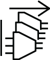
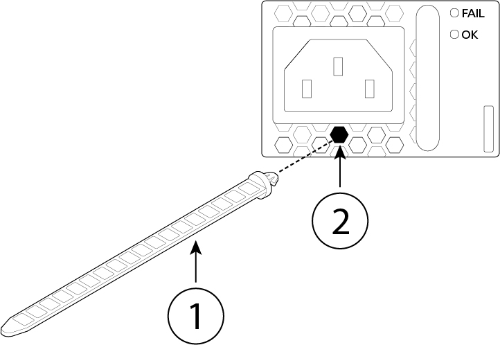
To remove a network module from the chassis, loosen the captive screw on the lower left side of the network module and pull out the handle that is connected to the screw. This mechanically ejects the network module from the slot.
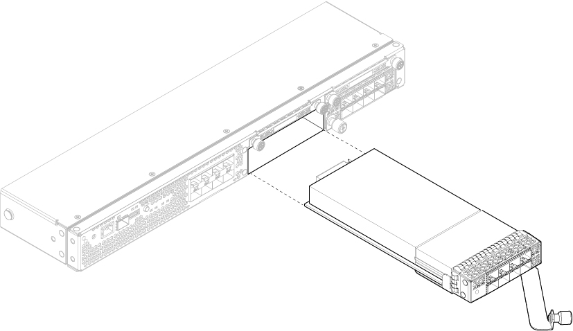
Figure 1. Remove the Network Module
If the slot is to remain empty, install a blank faceplate to ensure proper airflow and to keep dust out of the chassis; otherwise, install another network module.

Step 4

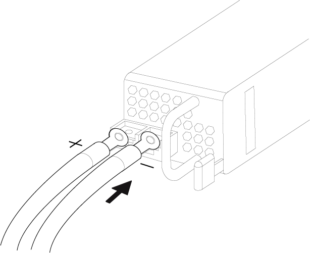
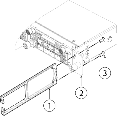
To replace a network module, hold the network module in front of the network module slot on the right of the chassis and pull the network module handle out.

Step 5

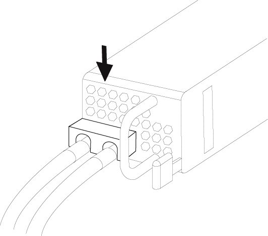
Slide the network module into the slot and push it firmly into place until the handle is flush with the front of the network module.

Step 6

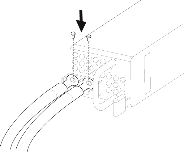
Tighten the captive screw on the lower left side of the network module.

Step 7

Do one of the following:

  1. Power up the chassis so that the new network module is recognized (if the new network module does not support hot swapping).

  2. Bring the new network module online using the appropriate CLI command (if the new network module supports hot swapping). The saved network module configuration is automatically reapplied when the network module is back online.

    Note


    If you install a network module that is a different PID than the original network module, the saved configuration is deleted and the default configuration is applied. You must enter the acknowledge command to confirm the network module PID change:


What to do next

Follow the procedures in the FXOS Configuration Guide to connect to the network module and make sure that it has been discovered correctly by the Firepower 4100.

Remove and Replace the Fan Module

You can remove and replace fan modules while the system is running. The air flow moves from front to back. If you remove a fan or a fan fails, the other fans operate at full speed, which can be noisy.

The system supports operation with a single fan failure (N+1 fan redundancy), but do not run the system for an extended amount of time without all fan modules installed. Keep removal and replacement at three minutes. Remove and replace one fan module at a time


Caution


Once you have aligned the fan with the fan slot, insert the new fan within five seconds. Do not partially engage the fan module and let the fan spin in the wrong direction before fully seating it.


Safety Warnings

Take note of the following component replacement safety warnings:


Warning


Statement 1028—More Than One Power Supply

This unit might have more than one power supply connection. To reduce risk of electric shock, remove all connections to de-energize the unit.


Warning


Statement 1073—No User-Serviceable Parts

There are no serviceable parts inside. To avoid risk of electric shock, do not open.


Warning


Statement 1089—Instructed and Skilled Person Definitions

An instructed person is someone who has been instructed and trained by a skilled person and takes the necessary precautions when working with equipment.

A skilled person or qualified personnel is someone who has training or experience in the equipment technology and understands potential hazards when working with equipment.

There are no serviceable parts inside. To avoid risk of electric shock, do not open.


Warning


Statement 1090—Installation by Skilled Person

Only a skilled person should be allowed to install, replace, or service this equipment. See statement 1089 for the definition of a skilled person.

There are no serviceable parts inside. To avoid risk of electric shock, do not open.


Warning


Statement 1091—Installation by an Instructed Person

Only an instructed person or skilled person should be allowed to install, replace, or service this equipment. See statement 1089 for the definition of an instructed or skilled person.

There are no serviceable parts inside. To avoid risk of electric shock, do not open.


Procedure


Step 1

To remove a fan module, face the rear of the chassis, and grasp the handle of the fan module.

Step 2

Squeeze the handle to disengage the latches on the left and right of the fan module.

Step 3

Pull the fan module out of the chassis.

Figure 2. Remove the Fan Module

Step 4

To replace a fan module, hold the fan module in front of the fan slot.

Step 5

Push the fan module into the chassis until it is properly seated and the latches snap into place.

If the system is powered on, listen for the fans. You should immediately hear the fans operating. If you do not hear the fans, make sure the fan module is inserted completely into the chassis and the faceplate is flush with the outside surface of the chassis.

Step 6

Verify that the fan is operational by checking the fan module LED. See Front Panel LEDs for a description of the fan LEDs.


Remove and Replace the SSD

Although the hardware supports removing and replacing SSDs while the system is running, the software does not currently support hot swapping. You must power down the chassis to remove and replace SSDs.


Note


If your Firepower 4100 is running Firepower Threat Defense software, we recommend that you upgrade to the latest version to take advantage of software updates that enhance SSD management performance and longevity.


You storage SSD must be installed in slot 1 and must be present. Slot 1 is reserved for the logical device application instance (threat defense or ASA). Only an optional MSP can be installed in the second SSD slot (SSD slot 2). The MSP stores threat detection results for use in future analysis. It supports the Advanced Malware Protection software feature. The MSP is supported beginning in FXOS 2.0.1. It is used as both storage and as the Malware application repository. RAID is not supported.


Caution


Do not switch the two SSDs. The storage SSD must be installed in slot 1. The optional MSP SSD must be installed in slot 2. If you remove it and install it in slot 1, all stored file capture data is lost.


Safety Warnings

Take note of the following component replacement safety warnings:


Warning


Statement 1028—More Than One Power Supply

This unit might have more than one power supply connection. To reduce risk of electric shock, remove all connections to de-energize the unit.


Warning


Statement 1073—No User-Serviceable Parts

There are no serviceable parts inside. To avoid risk of electric shock, do not open.


Warning


Statement 1089—Instructed and Skilled Person Definitions

An instructed person is someone who has been instructed and trained by a skilled person and takes the necessary precautions when working with equipment.

A skilled person or qualified personnel is someone who has training or experience in the equipment technology and understands potential hazards when working with equipment.

There are no serviceable parts inside. To avoid risk of electric shock, do not open.


Warning


Statement 1090—Installation by Skilled Person

Only a skilled person should be allowed to install, replace, or service this equipment. See statement 1089 for the definition of a skilled person.

There are no serviceable parts inside. To avoid risk of electric shock, do not open.


Warning


Statement 1091—Installation by an Instructed Person

Only an instructed person or skilled person should be allowed to install, replace, or service this equipment. See statement 1089 for the definition of an instructed or skilled person.

There are no serviceable parts inside. To avoid risk of electric shock, do not open.


Procedure


Step 1

Save your configuration.

Step 2

Power down the chassis by moving the power switch to the OFF position. See Features for more information about the power switch.

Step 3

To remove an SSD, face the front of the chassis, loosen the two captive screws on the SSD, and gently pull it out of slot 1 of the chassis.

Figure 3. Remove the SSD

Step 4

To replace the SSD, make sure the power switch is still in the OFF position, and then hold the SSD in front of slot 1 and push it in gently until it is seated.

Step 5

To install the MSP SSD, make sure the power switch is still in the OFF position and then remove the blank faceplate in slot 2 by loosening the captive screws on either side of the faceplate.

Step 6

Hold the MSP SSD in front of slot 2 and push it in gently until it is seated.

Caution


Do not switch the two SSDs. Only the optional MSP SSD can be installed in slot 2. If you remove it and install it in slot 1, all stored file capture data is lost.

Step 7

Tighten the captive screws on either side of the SSD.

Step 8

Verify that the SSD is operational by checking the SSD LED. See Front Panel LEDs for a description of the fan LEDs.


Remove and Replace the Power Supply Module

You can remove and replace power supply modules while the system is running.

Safety Warnings

Take note of the following power and component removal safety warnings:


Warning


Statement 1003—DC Power Disconnection

To reduce risk of electric shock or personal injury, disconnect DC power before removing or replacing components or performing upgrades.


Warning


Statement 1005—Circuit Breaker

This product relies on the building’s installation for short-circuit (overcurrent) protection. To reduce risk of electric shock or fire, ensure that the protective device is rated not greater than:

AC: 20A

DC: 40A


Warning


Statement 1017—Restricted Area

This unit is intended for installation in restricted access areas. Only skilled, instructed, or qualified personnel can access a restricted access area.


Warning


Statement 1022—Disconnect Device

To reduce the risk of electric shock and fire, a readily accessible disconnect device must be incorporated in the fixed wiring.


Warning


Statement 1028—More Than One Power Supply

This unit might have more than one power supply connection. To reduce risk of electric shock, remove all connections to de-energize the unit.


Warning


Statement 1029—Blank Faceplates and Cover Panels

Blank faceplates and cover panels serve three important functions: they reduce the risk of electric shock and fire, they contain electromagnetic interference (EMI) that might disrupt other equipment, and they direct the flow of cooling air through the chassis. Do not operate the system unless all cards, faceplates, front covers, and rear covers are in place.


Warning


Statement 1073—No User-Serviceable Parts

There are no serviceable parts inside. To avoid risk of electric shock, do not open.


Warning


Statement 1046—Installing or Replacing the Unit

To reduce risk of electric shock, when installing or replacing the unit, the ground connection must always be made first and disconnected last.

If your unit has modules, secure them with the provided screws.


Warning


Statement 1089—Instructed and Skilled Person Definitions

An instructed person is someone who has been instructed and trained by a skilled person and takes the necessary precautions when working with equipment.

A skilled person or qualified personnel is someone who has training or experience in the equipment technology and understands potential hazards when working with equipment.

There are no serviceable parts inside. To avoid risk of electric shock, do not open.


Warning


Statement 1090—Installation by Skilled Person

Only a skilled person should be allowed to install, replace, or service this equipment. See statement 1089 for the definition of a skilled person.

There are no serviceable parts inside. To avoid risk of electric shock, do not open.


Warning


Statement 1091—Installation by an Instructed Person

Only an instructed person or skilled person should be allowed to install, replace, or service this equipment. See statement 1089 for the definition of an instructed or skilled person.

There are no serviceable parts inside. To avoid risk of electric shock, do not open.


Procedure


Step 1

To remove a power supply module, face the back of the chassis and grasp the handle.

Step 2

Press the latch found on the lower right of the power supply to disengage the power supply.

Step 3

Place your other hand under the power supply module to support it while you slide it out of the chassis.

Figure 4. Remove the Power Supply Module
If the slot is to remain empty, install a blank faceplate to ensure proper airflow and to keep dust out of the chassis; otherwise, install another power supply module.

Step 4

To replace a power supply module, hold the power supply module with both hands and slide it into the power supply module bay.

Step 5

Push in the power supply module gently until you hear the latch engage and it is seated. Verify the power supply module is operating correctly by checking the power supply module LED. See Power Supply Modules for a description of the power supply module LEDs.


Connect the DC Power Supply Module

This procedure describes how to install the DC power supply input power leads to the Firepower 4100 DC input power supply on the rear PDU of the chassis.

Before You Begin
  • The color coding of the DC input power supply leads depends on the color coding of the DC power source at your site. Make sure that the lead color coding you choose for the DC input power supply matches the lead color coding used at the DC power source and verify that the power source is connected to the negative (–) terminal and to the positive (+) terminal on the power supply.

  • For DC input power cables, the wire gauge is based on the National Electrical Code (NEC) and local codes for 26 amp service at nominal DC input voltage (–40/–72 VDC). One pair of cable leads, source DC (–) and source DC return (+), are required for each power distribution unit (PDU). These cables are available from any commercial cable vendor. All DC input power cables for the chassis should be 10 gauge wire and cable lengths should match within 10 percent of deviation.

  • Tools needed:

    • Phillips head screwdriver

    • 10-mm wrench or socket

    • Connectors and wire for the DC circuit or circuits

Each DC input power cable is terminated at the PDU by a cable lug, as shown in the following figure.


Note


DC input power cables must be connected to the PDU terminal studs in the proper positive (+) and negative (–) polarity. In some cases, the DC cable leads are labeled, which is a relatively safe indication of the polarity. However, you must verify the polarity by measuring the voltage between the DC cable leads. When making the measurement, the positive (+) lead and the negative (–) lead must always match the (+) and (–) labels on the power distribution unit.


Figure 5. DC Input Power Cable Lug

Note


To avoid hazardous conditions, all components in the area where DC input power is accessible must be properly insulated. Therefore, before installing the DC cable lugs, be sure to insulate the lugs according to the manufacturer's instructions


Safety Warnings

Take note of the following power and component removal safety warnings:


Warning


Statement 1003—DC Power Disconnection

To reduce risk of electric shock or personal injury, disconnect DC power before removing or replacing components or performing upgrades.


Warning


Statement 1005—Circuit Breaker

This product relies on the building’s installation for short-circuit (overcurrent) protection. To reduce risk of electric shock or fire, ensure that the protective device is rated not greater than:

AC: 20A

DC: 40A


Warning


Statement 1017—Restricted Area

This unit is intended for installation in restricted access areas. Only skilled, instructed, or qualified personnel can access a restricted access area.


Warning


Statement 1022—Disconnect Device

To reduce the risk of electric shock and fire, a readily accessible disconnect device must be incorporated in the fixed wiring.


Warning


Statement 1028—More Than One Power Supply

This unit might have more than one power supply connection. To reduce risk of electric shock, remove all connections to de-energize the unit.


Warning


Statement 1029—Blank Faceplates and Cover Panels

Blank faceplates and cover panels serve three important functions: they reduce the risk of electric shock and fire, they contain electromagnetic interference (EMI) that might disrupt other equipment, and they direct the flow of cooling air through the chassis. Do not operate the system unless all cards, faceplates, front covers, and rear covers are in place.


Warning


Statement 1073—No User-Serviceable Parts

There are no serviceable parts inside. To avoid risk of electric shock, do not open.


Warning


Statement 1046—Installing or Replacing the Unit

To reduce risk of electric shock, when installing or replacing the unit, the ground connection must always be made first and disconnected last.

If your unit has modules, secure them with the provided screws.


Warning


Statement 1089—Instructed and Skilled Person Definitions

An instructed person is someone who has been instructed and trained by a skilled person and takes the necessary precautions when working with equipment.

A skilled person or qualified personnel is someone who has training or experience in the equipment technology and understands potential hazards when working with equipment.

There are no serviceable parts inside. To avoid risk of electric shock, do not open.


Warning


Statement 1090—Installation by Skilled Person

Only a skilled person should be allowed to install, replace, or service this equipment. See statement 1089 for the definition of a skilled person.

There are no serviceable parts inside. To avoid risk of electric shock, do not open.


Warning


Statement 1091—Installation by an Instructed Person

Only an instructed person or skilled person should be allowed to install, replace, or service this equipment. See statement 1089 for the definition of an instructed or skilled person.

There are no serviceable parts inside. To avoid risk of electric shock, do not open.


Procedure


Step 1

Install the DC power supply module in the chassis and make note of the bay number so you can connect the wiring to the correct terminals on the DC power supply module at the rear of the chassis. See Remove and Replace the Power Supply Module for the procedure.

Step 2

Verify that the power is off to the DC circuit on the power supply module that you are installing.

Step 3

Make sure that all site power and grounding requirements have been met.

Step 4

To remove the plastic cover from the terminal block, insert a flat screw driver on the side of the plastic cover and pry it off.

Figure 6. Remove the Plastic Cover

Step 5

To prevent any contact with metal lead on the ground wire and the plastic cover, you must wrap the positive and negative lead cables with sleeving. Insulate the lug with shrink sleeving for each lead wire if using noninsulated crimp terminals. Sleeving is not required for insulated terminals.

Step 6

Remove the two M5 screws.

Figure 7. Remove the M5 Screws

Step 7

For easier cable management, insert the negative lead cable first. Replace the grounding lug with the cable in the following order—wire terminal, then the screw with the captive washer.

Figure 8. Insert the Cables

Step 8

Tighten the M5 screw with the captive washer to the recommended torque of 5 in-lbs for the positive stud and wire. Secure the wires coming in from the terminal block so that they cannot be disturbed by casual contact.

Figure 9. Tighten the M5 Screws

Step 9

Replace the terminal block plastic cover. The plastic cover is slotted and keyed to fit correctly over the terminal block. This cover should always be in place when power is applied to the terminals.

Figure 10. Replace the Plastic Cover

Step 10

Set the DC disconnect switch in the circuit to ON. In a system with multiple power supplies, connect each power supply to a separate DC power source. In the event of a power source failure, if the second source is still available, it can maintain system operation.

Step 11

Verify power supply operation by checking the power supply LED on the front of the chassis. See Front Panel LEDs for a description of the LEDs.


Secure the Power Cord on the AC Power Supply Module

Tie Wrap and Clamp

To secure the power supply module against accidental removal and thus prevent disrupting system performance, use the tie wrap and clamp provided in the accessories kit that ships with your Firepower 4100. There are two different tie wrap and clamp combinations to be used with either the Flextronics or Artesyn power supply module.

To verify which power supply module you have, look at the vendor name on the top of the power supply module. If you cannot remove the power supply module, you can count the number of full hexagonal vent holes on the front of the power supply module in the row directly next to the word 'FAIL.' Flextronics has five holes and Artesyn has four holes.

The black tie wrap is used with the Flextronics power supply module and the off-white tie wrap is used with the Artesyn power supply module. The black clamp works with both. See the figures below.

Safety Warnings

Take note of the following component replacement safety warnings:


Warning


Statement 1028—More Than One Power Supply

This unit might have more than one power supply connection. To reduce risk of electric shock, remove all connections to de-energize the unit.


Warning


Statement 1073—No User-Serviceable Parts

There are no serviceable parts inside. To avoid risk of electric shock, do not open.


Warning


Statement 1089—Instructed and Skilled Person Definitions

An instructed person is someone who has been instructed and trained by a skilled person and takes the necessary precautions when working with equipment.

A skilled person or qualified personnel is someone who has training or experience in the equipment technology and understands potential hazards when working with equipment.

There are no serviceable parts inside. To avoid risk of electric shock, do not open.


Warning


Statement 1090—Installation by Skilled Person

Only a skilled person should be allowed to install, replace, or service this equipment. See statement 1089 for the definition of a skilled person.

There are no serviceable parts inside. To avoid risk of electric shock, do not open.


Warning


Statement 1091—Installation by an Instructed Person

Only an instructed person or skilled person should be allowed to install, replace, or service this equipment. See statement 1089 for the definition of an instructed or skilled person.

There are no serviceable parts inside. To avoid risk of electric shock, do not open.


Procedure


Step 1

Attach the clamp to the tie wrap by holding the clamp with the loop side on the bottom and sliding the tie wrap through the box-shaped channel above the clamp (see the following figure).

One side of the tie wrap has evenly spaced ridges and the other is smooth. Be sure the ridged side is face up and that you slide it through the open side of the channel. You will hear a click as the tie slides through—it moves in one direction only. To remove the tie wrap from the clamp, push the lever on the closed side of the box-shaped channel and slide out the tie wrap.

Figure 11. Tie Wrap Through the Box Channel of the Clamp

1

Tie wrap

2

Box channel

Step 2

Attach the clamp to the power supply module:

  1. Locate the hexagonal ventilation hole on the power supply module at the center of the plug just below the power connector body (see the following figures).

  2. Plug the snapping portion of the tie wrap into the hexagonal hole.

  3. With the clamp side facing up, push the tie wrap in until it is fully engaged.

    Caution


    Make sure you have the correct location because you cannot remove the tie wrap from the power supply module once you have installed it without damaging the tie wrap.

    Figure 12. Flextronics Power Supply Module

    1

    Flextronics tie wrap

    2

    Hexagonal hole

    Figure 13. Artesyn Power Supply Module

    1

    Artesyn tie wrap

    2

    Hexagonal hole

Step 3

Secure the clamp:

  1. Plug in the power supply power cord and wrap the clamp around the over mold portion of the power cord.

  2. Squeeze the clamp ends together to the power supply so that the annular teeth engage with the mate on the clamp.

  3. Make sure the clamp fits snugly into the over mold.

  4. Adjust the clamp position on the tie wrap so that the clamp is tight against the front of the over mold and the power cord cannot be removed by lightly pulling on it.

    Figure 14. Clamp on Over Mold of Power Cord

    1

    Power cord

    2

    Power cord over mold

    3

    Tie clamp annular teeth

    4

    Direction to squeeze the clamp tabs

    5

    Clamp release tabs

Step 4

If you need to remove the power cord, push the release tab on the clamp to force the annular clamp teeth to disengage and the clamp opens up. You can then remove the clamp from the power cord.


Install the FIPS Opacity Shield


Caution


This procedure should be performed only by the Crypto Officer.


Note


Because the FIPS opacity shield covers the serial number on the chassis, you need to copy the serial number on a label and attach it to the chassis where it can be retrieved or viewed easily before you install the FIPS opacity shield. You need the serial number when you call Cisco TAC.


Before you begin

You need the following to install the FIPS opacity shield:

  • #1 Phillips screwdriver

  • The following items from the FIPS kit:

    • One FIPS opacity shield

    • Four 8-32 x 0.375-inch screws used to attach the FIPS opacity shield to the cable management brackets

    • 15 tamper-evident labels (TELs)

  • The following items from the Firepower 4100 accessory kit:

    • Two cable management brackets

    • Four 8-32 x 0.375-inch screws used to attach the cable management brackets to the slide rail locking brackets

Procedure


Step 1

Copy the serial number on a label and attach it to the chassis where it can be retrieved easily for future use if needed. To find the serial number, see Serial Number Location.

Step 2

Pull the chassis out of the rack until the release latches catch.

Step 3

If you have not already done so, attach a slide rail locking bracket to each side of the chassis using the six 8-32 x 0.375-inch Phillips screws provided in the accessory kit.

Note


You should have completed this step while preforming the procedure described in Rack-Mount the Chassis.

Figure 15. Attach the Slide Rail Locking Bracket to the Side of the Chassis

1

Chassis

2

Slide rail locking bracket

3

8-32 x 0.375-inch Phillips screws (three per side)

Step 4

Attach a cable management bracket to each slide rail locking bracket using the four 8-32 x 0.375-inch Phillips screws provided in the accessory kit.

Figure 16. Attach the Cable Management Bracket to the Slide Rail Locking Bracket

1

Cable management bracket

2

Slide rail locking bracket

3

8-32 x 0.375 inch Phillips screws (two per side)

Step 5

Connect the cables to the ports. Install the cables according to your default software configuration as described in the Cisco Firepower 4100 Getting Started Guide. Make sure that the cables have enough slack to route them through the cable mounting brackets (as shown in Step 6 below).

Note


If you are installing the FIPS opacity shield after the initial product installation, the cables are connected. If the attached cables do not have enough slack to route them through the cable mounting brackets (as shown below), you will have to turn the power off on the appliance, remove the cables, route the cables through the cable mounting brackets, reattach the cables, and continue with Step 7 below.

Step 6

Route the cables through the openings in the cable management brackets.

Figure 17. Route the Cables Through the Cable Management Brackets

Step 7

Attach the FIPS opacity shield to the cable management brackets using the four 8-32 x 0.375-inch Phillips screws provided in the FIPS kit.

Figure 18. Attach the FIPS Opacity Shield to the Cable Management Brackets

1

FIPS opacity shield

2

8-32 x 0.375-inch Phillips screws (two per side)

3

Cable management bracket

Step 8

Attach the 15 TELs. For information on the procedure and correct placement of the TELs, see the Tamper Evidence Label (TEL) Placement section (section 2.13 ) in the FIPS 140-2 Non Proprietary Security Policy Level 2 Validation document.

Step 9

Attach the power cable to the chassis and connect it to an electrical outlet.

Step 10

Press the power switch on the rear panel.

Step 11

Check the power LED on the front panel. See Front Panel LEDs for a description of the power LED. Solid green indicates that the chassis is powered on.

Note


When you toggle the power switch from ON to OFF, it takes several seconds for the system to power down. Do not remove the power cable until the power LED is off. After removing power from the chassis either by moving the power switch to OFF or unplugging the power cord, wait at least 10 seconds before turning power back ON.

Step 12

See the Cisco Firepower 4100 Getting Started Guide for further configuration information.