Multicast Overlay Routing

The Cisco SD-WAN multicast overlay implementation extends native multicast by creating a secure optimized multicast tree that runs on top of the overlay network.

The Cisco SD-WAN multicast overlay software uses Protocol Independent Multicast Sparse Mode (PIM-SM) for multicasting traffic on the overlay network. PIM-SM builds unidirectional shared trees rooted at a rendezvous point (RP), and each multicast group has one shared tree that is rooted at a single RP. Once a shared tree has been built such that a last-hop router learns the IP address for the multicast source, the router engages in a switchover from the shared tree to initiate the construction of a source (or shortest-path) tree. The source tree uses the lowest metric path between the source and last-hop router, which may be entirely, partially, or not at all congruent with the shared tree.

Supported Protocols

Cisco SD-WAN overlay multicast network supports the Protocol Independent Multicast (PIM) and Internet Group Management Protocol (IGMP) and multicast template configurations on all the platforms.

PIM

Viptela overlay multicast supports PIM version 2 (defined in RFC 4601 ), with some restrictions.

On the service side, the Viptela software supports native multicast. A vEdge router appears as a native PIM router and establishes PIM neighborship with other PIM routers at a local site. To properly extend multicast trees into the overlay network, a vEdge router may require other supporting routers in a local site. If a PIM-SM RP is required at a site, that function must be provided by a non-Viptela router, because the vEdge router currently has no native support for the rendervouz point functionality. Receivers residing downstream of a vEdge router can join multicast streams by exchanging IGMP membership reports directly with the device, and no other routers are required. This applies only to sites that have no requirement for supporting local sources or PIM SM rendezvouz points.

On the transport side, PIM-enabled vEdge routers originate multicast service routes (called multicast autodiscover routes),sending them via OMP to the vSmart controllers. The multicast autodiscover routes indicate whether the router has PIM enabled and whether it is a replicator. If the router is a replicator and the load threshold has been configured, this information is also included in the multicast autodiscover routes. Each PIM router also conveys information learned from the PIM join messages sent by local-site multicast-enabled routers, including multicast group state, source information, and RPs. These routes assist vEdge routers in performing optimized joins across the overlay when joining existing multicast sources.

vEdge routers support PIM source-specific mode (SSM), which allows a multicast source to be directly connected to the router.

PIM Scalability Information

When configuring PIM, the following scalability limits apply:

  • Any single vEdge router supports a maximum of 1024 multicast state entries. Note that a (*,G) and an (S,G) for the same group count as two entries.

  • The 1024 multicast state entries are shared across all configured VPNs on a single vEdge router.

  • Each state entry can contain a maximum of 64 service-side entries and a maximum of 256 transport-side entries in its outgoing interface list (OIL).

Rendezvous Points

The root of a PIM multicast shared tree resides on a router configured to be a rendezvous point (RP). Each RP acts as the RP and the root of a shared tree (or trees) for specific multicast group ranges. In the Viptela overlay network, RPs are non-Viptela routers that reside in the local-site network. The RP function is typically assigned to one or two locations in the network; it is not required at every site. vEdge routers do not currently support the RP functionality, so non-Viptela routers must provide this function in the applicable sites.

The Viptela software supports the auto-RP protocol for distributing RP-to-group mapping information to local-site PIM routers. With this information, each PIM router has the ability to forward joins to the correct RP for the group that a downstream IGMP client is attempting to join. Auto-RP updates are propagated to downstream PIM routers if such routers are present in the local site.

Replicators

For efficient use of WAN bandwidth, strategic vEdge routers can be deployed and configured as replicators throughout the overlay network. Replicators mitigate the requirement for an ingress router to replicate a multicast stream once for each receiver.

As discussed above, replicators advertise themselves, via OMP multicast-autodiscover routes, to the vSmart controllers in the overlay network. The controllers then forward the replicator location information to the PIM-enabled vEdge routers that are in the same VPN as the replicator.

A replicator vEdge router receives streams from multicast sources, replicates them, and forwards them to multicast receivers. The details of the replication process are discussed below, in the section Multicast Traffic Flow through the Overlay Network.

A replicator is typically vEdge router located at a colo site or another site with a higher-speed, or a high-speed, connection to the WAN transport network.

Multicast Service Routes

vEdge routers send multicast service routes to the vSmart controller via OMP. From these routes, the controller processes and forwards joins for requested multicast groups towards the source address as specified in the original PIM join message that helped originate the OMP multicast service route. The source address can be either the IP address of an RP if the originating router is attempting to join the shared tree or the IP address of the actual source of the multicast stream if the originating router is attempting to join the source tree.

IGMP

Cisco SD-WAN overlay multicast routing supports the Internet Group Management Protocol (IGMP) version 2 (defined in RFC 2236 ). Cisco vEdge devices use IGMP to process receiver membership reports for the hosts in a particular VPN and to determine, for a given group, whether multicast traffic should be forwarded and state should be maintained. vEdge routers listen for both IGMPv1 and IGMPv2 group membership reports.
Traffic Flow in Multicast Overlay Routing

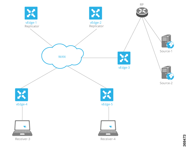
Let’s look at the high-level topology of the Cisco SD-WAN overlay network multicast solution to illustrate how traffic from multicast sources is delivered to multicast receivers. The topology contains five vEdge routers:

  • vEdge router vEdge-3 is located at a site with two multicast sources, Source-1 and Source-2. This site also has a non-vEdge router that functions as a PIM-SM RP. Even though the vEdge-3 router is the ingress router for streams from these two multicast sources, it performs no packet replication. Instead, it forwards the multicast streams to replicators in the overlay network. The vEdge-3 router has learned the addresses of the replicators via OMP from a vSmart controller.

  • vEdge routers vEdge-1 and vEdge-2 are two multicast replicators in the overlay network. Their job as replicators is to receive streams from multicast sources, replicate the streams, and then forward them to receivers. In this topology, the vEdge-3 router forwards the multicast streams from the two multicast sources in its local network to vEdge-1 or vEdge2, or both, and these routers then replicate and forward the streams to the receivers located in the local sites behind vEdge routers vEdge-4 and vEdge5. Which replicator receives a stream depends on the group address, the identity of the vEdge routers that joins that given group, and the current load of the replicator. The typical situation is that only a single replicator is replicating traffic for a given group, but this may vary depending on the physical scope of the given group.

  • vEdge router vEdge4 is located at a site that has one multicast receiver, Receiver-3, which receives streams from Source-1 and Source-2.

  • vEdge router vEdge5 is located at another site with one multicast receiver, Receiver-4. This receiver gets streams only from one source, Source-1.

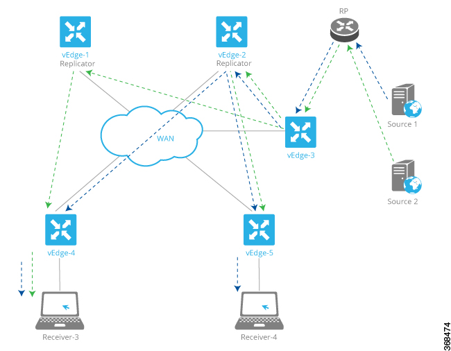
Now, let’s examine how multicast traffic flows from the sources to the receivers.

The two multicast sources, Source-1 and Source-2, send their multicast streams (the blue stream from Source-1 and the green stream from Source-2) to the RP. Because the destination IP addresses for both streams are at remote sites, the RP forwards them to vEdge-3 for transmission onto the transport/WAN network. vEdge-3 has learned from the vSmart controller that the network has two replicators, vEdge-1 and vEdge-2, and so forwards the two multicast streams to them, without first replicating the streams.

The two replicators have learned from a vSmart controller the locations of multicast receivers for the two streams. The vEdge-1 replicator makes one copy of the green stream and forwards it to vEdge-4, which in turns forwards it to the Receiver-3. The vEdge-2 replicator makes one copy of the green stream, which it forwards to vEdge-5 (from which it goes on to Receiver-4), and it makes two copies of the blue stream, which it forwarsa to vEdge-4 and vEdge-5 (and which they then forward to the two receivers).

Now, let's look at the multicast configurations on the five vEdge routers:

  • vEdge router vEdge-1 is a PIM replicator for a particular VPN. If we assume that no multicast sources, receivers, or RPs are located in its local network, the configuration of this router is simple: In the VPN, enable the replicator functionality, with the router multicast-replicator local command, and enable PIM, with the router pim command.

  • vEdge router vEdge-2 also acts only as a replicator in the same VPN as vEdge-1, and you configure it with the same commands, router multicast-replicator local and router pim, when configuring the VPN. Each replicator can accept a maximum number of new PIM joins, and when this threshold value is reached, all new joins are sent to the second replicator. (If there is only one replicator, new joins exceeding the threshold are dropped.)

  • vEdge router vEdge-4 runs PIM. You enable PIM explicitly on the service side within a VPN, specifying the service-side interface that connects to the multicast domain in the local network. So within the VPN, you include the router pim interface command. You can also enable auto-RP with the router pim auto-rp command. On the transport side, no explicit configuration is required. The vEdge router automatically directs multicast traffic—both OMP control plane messages and multicast streams—to VPN 0, which is the WAN transport VPN.

  • vEdge router vEdge-5 is also configured to run PIM in the same way as vEdge-4: You configure the service-side interface name and RP information.

PIM must be enabled in the same VPN on all five of these vEdge routers so that the multicast streams can be transmitted and received.

Configure Multicast Overlay Routing

For any vEdge routers to be able to participate in the multicast overlay network, you configure PIM on those routers. You can optionally configure IGMP to allow individual hosts on the service side to join multicast groups within a particular VPN.

Limitations of Multicast Configuration

You cannot configure the following for multicast overlay routing:

  • Data policy

  • Access lists

  • Mirroring

Configure PIM Using vManage Templates

Use the PIM template for all vEdge Cloud and vEdge router devices.

Configure the PIM Sparse Mode (PIM-SM) protocol using vManage templates so that a router can participate in the Viptela multicast overlay network:

  1. Create a PIM feature template to configure PIM parameters, as described in this topic.

  2. Optionally, create an IGMP feature template to allow individual hosts on the service side to join multicast groups within a particular VPN. See Configure IGMP Using vManage Templaes.

  3. Optionally, create a Multicast feature template to configure a vEdge router to be a multicast replicator. See the Multicast help topic.

  4. Create a VPN feature template to configure parameters for the VPN that is running PIM. See the VPN help topic.

Create a PIM Feature Template

  1. In vManage NMS, select Configuration > Templates.

  2. In the Device tab, click Create Template.

  3. From the Create Template drop-down, select From Feature Template.

  4. From the Device Model drop-down, select the type of device for which you are creating the template.

  5. Click the Service VPN tab located directly beneath the Description field, or scroll to the Service VPN section.

  6. Click the Service VPN drop-down.
  7. Under Additional VPN Templates, located to the right of the screen, click PIM.

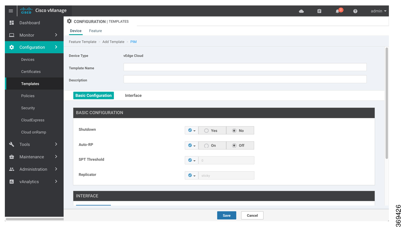
  8. From the PIM drop-down, click Create Template. The PIM template form is displayed. The top of the form contains fields for naming the template, and the bottom contains fields for defining PIM parameters.

  9. In the Template Name field, enter a name for the template. The name can be up to 128 characters and can contain only alphanumeric characters.

  10. In the Template Description field, enter a description of the template. The description can be up to 2048 characters and can contain only alphanumeric characters.

When you first open a feature template, for each parameter that has a default value, the scope is set to Default (indicated by a check mark), and the default setting or value is shown. To change the default or to enter a value, click the scope drop-down to the left of the parameter field and select one of the following:

Table 1.

Parameter Scope

Scope Description

Device Specific (indicated by a host icon)

Use a device-specific value for the parameter. For device-specific parameters, you cannot enter a value in the feature template. You enter the value when you attach a Viptela device to a device template .

When you click Device Specific, the Enter Key box opens. This box displays a key, which is a unique string that identifies the parameter in a CSV file that you create. This file is an Excel spreadsheet that contains one column for each key. The header row contains the key names (one key per column), and each row after that corresponds to a device and defines the values of the keys for that device. You upload the CSV file when you attach a Viptela device to a device template. For more information, see Create a Template Variables Spreadsheet .

To change the default key, type a new string and move the cursor out of the Enter Key box.

Examples of device-specific parameters are system IP address, hostname, GPS location, and site ID.

Global (indicated by a globe icon)

Enter a value for the parameter, and apply that value to all devices.

Examples of parameters that you might apply globally to a group of devices are DNS server, syslog server, and interface MTUs.

Configure Basic PIM

To configure PIM, select the Basic Configuration tab and configure the following parameters. Parameters marked with an asterisk are required to configure PIM.

Table 2.

Parameter Name

Description

Shutdown*

Ensure that No is selected, to enable PIM.

Auto-RP

Click On to enable auto-RP to enable automatic discovery of rendezvous points (RPs) in the PIM network so that the router receivea group-to-RP mapping updates. By default, auto-RP is disabled.

SPT Threshold

Specify the traffic rate, in kbps, at which to switch from the shared tree to the shortest-path tree (SPT). Configuring this value forces traffic to remain on the shared tree and travel via the RP instead of via the SPT.

Replicator

For a topology that includes multicast replicators, determine how the replicator for a multicast group is chosen:

  • Random—Choose the replicator at random.

  • Sticky—Always use the same replicator. This is the default.

To save the feature template, click Save.

Configure PIM Interfaces

If the router is just a multicast replicator and is not part of a local network that contains either multicast sources or receivers, you do not need to configure any PIM interfaces. The replicator learns the locations of multicast sources and receivers from the OMP messages it exchanges with the vSmart controller. These control plane messages are exchanged in the transport VPN (VPN 0). Similarly, other vEdge routers discover replicators dynamically, through OMP messages from the vSmart controller.

To configure PIM interfaces, select the Interface tab. Then click Add New Interface and configure the following parameters:

Table 3.

Parameter Name

Description

Name

Enter the name of an interface that participates in the PIM domain, in the format ge slot /port.

Hello Interval

Specify how often the interface sends PIM hello messages. Hello messages advertise that PIM is enabled on the router.Range: 1 through 3600 secondsDefault: 30 seconds

Join/Prune Interval

Specify how often PIM multicast traffic can join or be removed from a rendezvous point tree (RPT) or shortest-path tree (SPT). vEdge routers send join and prune messages to their upstream RPF neighbor.Range: 10 through 600 secondsDefault: 60 seconds

To edit an interface, click the pencil icon to the right of the entry.

To delete an interface, click the trash icon to the right of the entry.

To save the feature template, click Save.

Release Information

Configure PIM Using CLI

Enable PIM at a Site with Multicast Sources

For a vEdge router located at a site that contains one or more multicast sources, you enable PIM on the service-side interface or interfaces. These are the interfaces that face the local-site network. You enable PIM per VPN, so you must configure PIM and PIM interfaces for all VPNs support multicast services. You cannot configure PIM in VPN 0 (the transport VPN facing the overlay network) or in VPN 512 (the management VPN).

For each VPN, you must configure the name of the service-side interface. You can optionally configure auto-RP to receive group-to-RP mapping updates.

To configure PIM at a site with multicast sources:

  1. Configure a VPN for the PIM network:
    vEdge(config)# vpn vpn-id
    vpn-id can be any VPN number except VPN 0 (the transport VPN facing the overlay network) or VPN 512 (the management VPN).
  2. Configure the interfaces in the VPN:
    vEdge(config-vpn)# interface interface-name
    vEdge(config-interface)# ip address prefix/length 
    vEdge(config-interface)# no shutdown
    The interface names in the two interface names must be the same.
  3. Configure PIM and the interfaces that participate in the PIM network:
    vEdge(config-vpn)# router pim    
    ​vEdge(config-pim)# interface interface-name
    vEdge(config-interface)# no shutdown
    The interface name in the two interface commands must be the same.
  4. Optionally, modify PIM timers on the interface. The default PIM hello interval is 30 seconds, and the default join/prune interval is 60 seconds.
    vEdge(config-interface)#  hello-interval seconds
    vEdge(config-interface)#  join-prune-interval seconds
    The hello interval can be in the range of 1 through 3600 seconds. The join/prune interval can be in the range of 10 through 600 seconds.
  5. Optionally, enable automatic discover of rendezvous points (RPs) in the PIM network:
    vEdge(config-pim)#  auto-rp 

Here is an example of a PIM configuration on a vEdge router:

vpn 10
 router
  pim
    interface ge1/1
      no shutdown
    auto-rp

Enable PIM at a Site with Multicast Receivers

For a vEdge router located at a site that contains one or more multicast receivers, you enable PIM on the service-side interface or interfaces (the interfaces facing the local-site network). You enable PIM per VPN, so you must configure PIM and PIM interfaces for all VPNs support multicast services.

For each VPN, you must configure the name of the service-side interface.

To configure PIM at a site with multicast receivers:

  1. Configure a VPN for the PIM network:
    vEdge(config)# vpn vpn-id
    vpn-id can be any VPN number except VPN 0 (reserved for control plane traffic) or VPN 512 (the management VPN).
  2. Configure PIM and the interfaces that participate in the PIM network:
    vEdge(config-vpn)# router pim    
    ​vEdge(config-pim)# interface interface-name
  3. Configure the interface used by PIM in the PIM VPN:
    vEdge(config-vpn)# interface interface-name    
    vEdge(config-interface)# ip address prefix/length
    vEdge(config-interface)# no shutdown
    The interface names in the two interface names must be the same.
  4. By default, a vEdge router joins the shortest-path tree (SPT) immediately after the first packet arrives from a new source. To force traffic to remain on the shared tree and travel via the RP instead of via the SPT, configure the traffic rate at which to switch from the shared tree to the SPT:
    vEdge(config-vpn)# router pim spt-threshold kbps
                            
    The rate can be from 0 through 100 kbps.
  5. In a topology that includes multicast replicators, the Cisco SD-WAN software, by default, uses the same replicator for a multicast group. You can have the software choose the replicator randomly:
    vEdge(config-vpn)# router pim replicator-selection random

Here is an example of a PIM configuration on a vEdge router:

vEdge(config-vpn-2)# show full-configuration
vpn 2
 router
  pim
   interface ge0/7
   exit
  exit
 !
 interface ge0/7
  ip address 10.0.100.15/24
  no shutdown
 !
!

Configure a Multicast Replicator

For a vEdge router that is a replicator, the configuration has two parts: you configure the router to be a replicator, and you enable PIM on each VPN that participates in a multicast domain.

To configure a replicator:

  1. Configure a VPN for the PIM network:
    vEdge(config)# vpn vpn-id
    vpn-id can be any VPN number except VPN 0 (the transport VPN facing the overlay network) or VPN 512 (the management VPN).
  2. Configure the replicator functionality on the local vEdge router:
    vEdge(config-vpn)# router multicast-replicator local
  3. On the transport side, a single vEdge router acting as a replicator can accept a maximum of 1024 (*,G) and (S,G) joins. For each join, the router can accept 256 tunnel outgoing interfaces (OILs). To modify the number of joins the replicator can accept, change the value of the join threshold:
    vEdge(config-router)# multicast-replicator threshold number
  4. Enable PIM on each VPN that participates in a multicast domain:
    vEdge(config)# vpn vpn-id
    vEdge(config-vpn)# router pim
    If the router is just a replicator and is not part of a local network that contains either multicast sources or receivers, you do not need to configure any interfaces in the PIM portion of the configuration. The replicator learns the locations of multicast sources and receivers from the OMP messages it exchanges with the vSmart controller. These control plane messages are exchanged in the transport VPN (VPN 0). Similarly, the other vEdge routers discover replicators dynamically, through OMP messages from the vSmart controller.

Configure IGMP Using vManage Templates

Use the IGMP template for all vEdge Cloud and vEdge router devices. Internet Group Management Protocol (IGMP) allows vEdge routers to join multicast groups within a particular VPN.

To configure IGMP using vManage templates:

  1. Create an IGMP feature template to configure IGMP parameters.

  2. Create the interface in the VPN to use for IGMP. See the VPN-Interface-Ethernet help topic.

  3. Create a VPN feature template to configure VPN parameters. See the VPN help topic.

Navigate to the Template Screen and Name the Template

  1. In vManage NMS, select Configuration > Templates.

  2. In the Device tab, click Create Template.

  3. From the Create Template drop-down, select From Feature Template.

  4. From the Device Model drop-down, select the type of device for which you are creating the template.

  5. Click the Service VPN tab located directly beneath the Description field, or scroll to the Service VPN section.

  6. Click the Service VPN drop-down.
  7. Under Additional VPN Templates, located to the right of the screen, click IGMP.

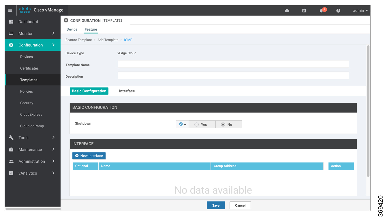
  8. From the IGMP drop-down, click Create Template. The IGMP template form is displayed. The top of the form contains fields for naming the template, and the bottom contains fields for defining IGMP parameters.

  9. In the Template Name field, enter a name for the template. The name can be up to 128 characters and can contain only alphanumeric characters.

  10. In the Template Description field, enter a description of the template. The description can be up to 2048 characters and can contain only alphanumeric characters.

When you first open a feature template, for each parameter that has a default value, the scope is set to Default (indicated by a check mark), and the default setting or value is shown. To change the default or to enter a value, click the scope drop-down to the left of the parameter field and select one of the following:

Table 4.

Parameter Scope

Scope Description

Device Specific (indicated by a host icon)

Use a device-specific value for the parameter. For device-specific parameters, you cannot enter a value in the feature template. You enter the value when you attach a Viptela device to a device template .

When you click Device Specific, the Enter Key box opens. This box displays a key, which is a unique string that identifies the parameter in a CSV file that you create. This file is an Excel spreadsheet that contains one column for each key. The header row contains the key names (one key per column), and each row after that corresponds to a device and defines the values of the keys for that device. You upload the CSV file when you attach a Viptela device to a device template. For more information, see Create a Template Variables Spreadsheet .

To change the default key, type a new string and move the cursor out of the Enter Key box.

Examples of device-specific parameters are system IP address, hostname, GPS location, and site ID.

Global (indicated by a globe icon)

Enter a value for the parameter, and apply that value to all devices.

Examples of parameters that you might apply globally to a group of devices are DNS server, syslog server, and interface MTUs.

Configure Basic IGMP Parameters

To configure IGMP, select the Basic Configuration tab to enable IGMP. Then, select the Interface tab and click Add New Interface to configure IGMP interfaces. All parameters listed below are required to configure IGMP.

Table 5.

Parameter Name

Description

Shutdown

nsure that No is selected to enable IGMP.

Interface Name

Enter the name of the interface to use for IGMP.

To add another interface, click the plus sign (+). To delete an interface, click the trash icon to the right of the entry.

Join Group Address

Click Add Join Group Address, and enter the address of a multicast group for the interface to join.

Click Add to add the new interface

To save the feature template, click Save.

Configure IGMP Using CLI

Configure IGMP to allow individual hosts on the service side to join multicast groups within a particular VPN.

Enable IGMP at a Site with Multicast Hosts

For VPNs in which you want to individual hosts to join multicast groups, you can enable IGMP on vEdge routers:

vEdge(config)#vpn vpn-id router igmp
vEdge(config-igmp)# interface interface-name

Ensure that the interface being used for IGMP is configured in the VPN:

vEdge(config)# vpn vpn-id
vEdge(config-vpn)# interface interface-name
vEdge(config-interface)# ip address prefix/length
vEdge(config-interface)# no shutdown

If desired, specify the multicast groups to initiate join requests with:

vEdge(config-igmp)# interface interface-name join-group group-ip-address

Configure the Interface Bandwidth Allowed for Multicast Traffic

By default, multicast traffic can use up to 20 percent of the interface bandwidth. You can change this allocation to a value from 5 to 100 percent:

vEdge(config)# system multicast-buffer-percent percentage

This systemwide configuration applies to all multicast-enabled interfaces on the vEdge router.

Multicast Routing CLI Reference

CLI commands for configuring and monitoring the IGMP, PIM, and Replicator routing protocols on vEdge routers.

IGMP Configuration and Monitoring Commands

Use the following commands to configure IGMP within a VPN on a vEdge router:

vpn vpn-id
  router
    igmp
      interface interface-name
        join-group group-address
      [no] shutdown

Use the following commands to monitor IGMP:

  • clear igmp interface —Clear the interfaces on which IGMP is enabled.

  • clear igmp protocol —Flush all IGMP groups and relearn them.

  • clear igmp statistics —Zero IGMP statistics.

  • show igmp groups —Display information about multicast groups.

  • show igmp interface —Display information about the interfaces on which IGMP is enabled.

  • show igmp statistics —Display IGMP statistics.

PIM and Multicast Replicator Configuration and Monitoring Commands

Use the following commands to configure PIM and multicast replicators within a VPN on a vEdge router:

vpn vpn-id
  router
    multicast-replicator local [threshold number]
vpn vpn-id
  router
    pim
      auto-rp
      interface interface-name
        hello-interval seconds
        join-prune-interval seconds
      replicator-selection       
      [no] shutdown
      spt-threshold kbps

Use the following commands to monitor PIM and multicastreplicators:

  • clear ip mfib record —Clear the statistics for a particular group, source, or VPN from the Multicast Forwarding Information Base (MFIB).

  • clear ip mfib stats —Clear all statistics from the MFIB.

  • clear pim interface —Relearn all PIM neighbors and joins.

  • clear pim neighbor —Clear the statistics for a PIM neighbor.

  • clear pim protocol —Clear all PIM protocol state.

  • clear pim statistics —Clear all PIM-related statistcs and relearn all PIM neighbors and joins.

  • show ip mfib oil —Display the list of outgoing interfaces from the MFIB.

  • show ip mfib stats —Display packet transmission and receipt statistics for active entries in the MFIB.

  • show ip mfib summary —Display a summary of all active entries in the MFIB.

  • show multicast replicator— List information about multicast replicators.

  • show multicast rpf—List multicast reverse-path forwarding information.

  • show multicast topology —List information related to the multicast domain topology.

  • show multicast tunnel —List information about the IPsec tunnels between multicast peers.

  • show omp multicast-auto-discover —List the peers that support multicast.

  • show omp multicast-routes —List the multicast routes that OMP has learned from PIM join messages.

  • show pim interface —List the interfaces that are running PIM.

  • show pim neighbor —List PIM neighbors.

  • show pim statistics —Display all PIM-related statistics.