Precision Time Protocol (PTP)

Precision Time Protocol (PTP) defines a method for distributing time across a network with its foundation based on the IEEE 1588-2008 standard.

This module describes the concepts around this protocol and details the various configurations involved.

PTP Overview

The Precision Time Protocol (PTP), defined in the IEEE 1588 standard, achieves synchronization at nanosecond precision of real-time clocks across networked devices. These clocks are structured in a Master-Client hierarchy. PTP identifies the port connected to the device with the most accurate clock, known as the Master clock. All other devices within the network synchronize their clocks with the Master clock, and referred to as members. Ongoing exchange of timing messages ensures continual synchronization. PTP ensures the selection of the best available clock as the time source of the network (referred to as the grandmaster clock), with all other network clocks synchronized to this clock.

Why PTP?

Smart grid power automation applications, such as peak-hour billing, virtual power generators, and outage monitoring and management, require precise time accuracy and stability. Timing precision improves network monitoring accuracy and troubleshooting ability.

In addition to providing time accuracy and synchronization, the PTP message-based protocol can be implemented on packet-based networks, such as Ethernet networks. The benefits of using PTP in an Ethernet network include:

  • Low cost and easy setup in existing Ethernet networks

  • Limited bandwidth requirement for PTP data packets

Routers and Delays

In an IP network, routers provide a full-duplex communication path between network devices. Routers send data packets to packet destinations using an IP address information contained in the packets. When the router attempts to send multiple packets simultaneously, the router buffers some packets so that they aren’t lost before they are sent. When the buffer is full, the router delays sending packets. This delay can cause device clocks on the network to lose synchronization with one another.

More delays can occur when packets entering a router are stored in its local memory while the router searches the address table to verify packet fields. This process causes variations in packet forwarding time latency, and these variations can result in asymmetrical packet delay times.

Adding PTP to a network can compensate for these latency and delay problems by correctly adjusting device clocks so that they stay synchronized with one another. PTP enables network routers to function as PTP devices, including boundary clocks (BCs) and transparent clocks (TCs).

For more information about PTP clock devices and their role in a PTP network, see the PTP Clocks section.

Key Terms and Concepts

PTP Clocks

A PTP network is made up of PTP-enabled devices and devices that aren’t using PTP. The PTP-enabled devices typically consist of the following clock types.

  • Grandmaster (GM)—A network device physically attached to the primary time source, all clocks are synchronized to the grandmaster clock.

  • Ordinary Clock (OC)—An ordinary clock is a 1588 clock with a single PTP port that can operate in one of the following modes:

    • Master mode—Distributes timing information over the network to one or more client clocks, thus allowing the client to synchronize its clock to the master.

    • Slave mode—Synchronizes its clock to a master clock. You can enable the slave mode on up to two interfaces simultaneously in order to connect to two different master clocks.

  • Boundary Clock (BC)—The device participates in selecting the best master clock and can act as the master clock if no better clocks are detected.

    The boundary clock starts its own PTP session with various downstream client clocks. The boundary clock mitigates the number of network hops and packet delay variations in the packet network between the Grandmaster and Client.

  • Transparent Clock (TC)—A transparent clock is a device or a switch that calculates the time it requires to forward traffic and updates the PTP time correction field to account for the delay, making the device transparent in terms of time calculations.

Port State Machine and Best Master Clock Algorithm

This provides a method to determine the state of the ports in the network that remain passive (neither master nor client), run as a master (providing time to other clocks in the network), or run as secondaries (receiving time from other clocks in the network).

Frequency and Time Selection

The selection of the source to synchronize the device clock frequency is made by frequency synchronization which is described in the Source and Selection Points section of the Frequency Synchronization module in this document. The Announce, Sync, and Delay-request frequencies must be the same on the master and client.

Delay Request-Response Mechanism

The Delay Request-response mechanism (defined in section 11.3 of IEEE Std 1588-2008) lets a client port estimate the difference between its own clock-time and the clock-time of its master. The following options are supported:

  • One-step mechanism - The timestamp for a Sync message is sent in the Sync message itself.

  • Two-step mechanism - The timestamp for a Sync message is sent later in a Follow-up message.

When running a port in Client state, a router can send Delay-request messages and handle incoming Sync, Follow-up, and Delay-response messages. The timeout periods for both Sync and Delay-response messages are individually configurable.

Hybrid Mode

Your router allows the ability to select separate sources for frequency and time-of-day (ToD). Frequency selection can be between any source of frequency available to the router, such as: BITS, GPS, SyncE, or IEEE 1588 PTP. The ToD selection is between the source selected for frequency and PTP, if available (ToD selection is from GPS, or PTP). This is known as hybrid mode, where a physical frequency source (BITS or SyncE) is used to provide frequency synchronization, while PTP is used to provide ToD synchronization.

Frequency selection uses the algorithm described in ITU-T recommendation G.781. The ToD selection is controlled using the time-of-day priority configuration. This configuration is found under the clock interface frequency synchronization configuration mode and under the global PTP configuration mode. It controls the order for which sources are selected for ToD. Values in the range of 1–254 are allowed, with lower numbers indicating higher priority.

The steps involved are detailed in this section Configuring PTP Hybrid Mode of the topic G.8275.1.

Time of Day (ToD) Support

The router receives GPS ToD messages in serial ASCII stream through the RS422 interface in one of the following configurable formats:

  • NTP Type 4

  • Cisco

Port States for PTP

State machine indicates the behavior of each port. The possible states are:

State

Description

INIT

Port isn’t ready to participate in PTP.

LISTENING

First state when a port becomes ready to participate in PTP: In this state, the port listens to PTP masters for a (configurable) period of time.

PRE-MASTER

Port is ready to enter the MASTER state.

MASTER

Port provides timestamps for any Client or boundary clocks that are listening.

UNCALIBRATED

Port receives timestamps from a Master clock but, the router’s clock isn’t yet synchronized to the Master clock.

SLAVE

Port receives timestamps from a Master clock and the router’s clock is synchronized to the Master clock.

PASSIVE

Port is aware of a better clock than the one it would advertise if it was in MASTER state and isn’t a Client clock to that Master clock.

How PTP Works?

Message-Based Synchronization

To ensure clock synchronization, PTP requires an accurate measurement of the communication path delay between the time source (master) and the receiver (client). PTP sends messages between the master and client device to determine the delay measurement. Then, PTP measures the exact message transmit and receive times and uses these times to calculate the communication path delay.

PTP then adjusts current time information contained in network data for the calculated delay, resulting in more accurate time information.

This delay measurement principle determines the path delay between devices on the network. The local clocks are adjusted for this delay using a series of messages sent between masters and clients. The one-way delay time is calculated by averaging the path delay of the transmit and receive messages. This calculation assumes a symmetrical communication path; however, routed networks don’t necessarily have symmetrical communication paths, due to the various asymmetries in the network.

Using transparent clocks, PTP provides a method to measure and account for the delay in a time-interval field in network timing packets. This makes the routers temporarily transparent to the master and client nodes on the network. An end-to-end transparent clock forwards all messages on the network in the same way that a router does.

To read a detailed description of synchronization messages, see the PTP Event Message Sequences section.

PTP Event Message Sequences

This section describes the PTP event message sequences that occur during synchronization.

Synchronizing with Boundary Clocks

The ordinary and boundary clocks configured for the delay request-response mechanism use the following event messages to generate and communicate timing information:

  • Sync

  • Follow_Up

  • Delay_Req

  • Delay_Resp

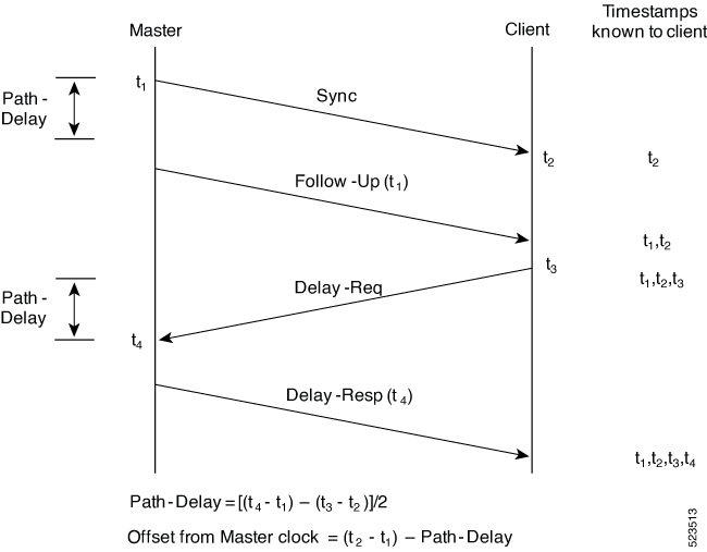
These messages are sent in the following sequence:

  • The master sends a Sync message to the client and notes the time (t1) at which it was sent.

  • The client receives the Sync message and notes the time of reception (t2).

  • The master conveys to the client the timestamp t1 by embedding the timestamp t1 in a Follow_Up message.

  • The client sends a Delay_Req message to the master and notes the time (t3) at which it was sent.

  • The master receives the Delay_Req message and notes the time of reception (t4).

  • The master conveys to the client the timestamp t4 by embedding it in a Delay_Resp message.

After this sequence, the client possesses all four timestamps. These timestamps can be used to compute the offset of the client clock relative to the master, and the mean propagation time of messages between the two clocks.

The offset calculation is based on the assumption that the time for the message to propagate from master to client is the same as the time required from client to master. This assumption isn’t always valid on an Ethernet/IP network due to asymmetrical packet delay times.

Figure 1. Detailed Steps—Boundary Clock Synchronization
Boundary clock synchronization

Synchronizing the Local Clock

In an ideal PTP network, the master and client clocks operate at the same frequency. However, drift can occur on the network. Drift is the frequency difference between the master and client clock. You can compensate for drift by using the time stamp information in the device hardware and follow-up messages (intercepted by the router) to adjust the frequency of the local clock to match the frequency of the master clock.

PTP Support Information

This table lists different types of support information related to PTP:

Transport Media

  • UDP over IPv4

  • UDP over IPv6

  • Ethernet

Messages

  • Signaling

  • Announce

  • Sync

  • Follow-up

  • Delay-request

  • Delay-response

  • Management

Transport Modes

  • Unicast: This is the default mode. All packets are sent as unicast messages. Unicast is applicable only for PTP over IP profiles.

  • Multicast: All packets are sent as multicast messages. Multicast is the only mode for PTP over ethernet profiles.

Timing Profile and Class Support Matrix

This table provides information about the timing profiles and class that are supported on the Cisco 8000 series routers and line cards.

Table 1. Timing Profile and Class Support Matrix

Hardware Module

Supported Profile

Cisco IOS XR Release

8711-32FH-M router

G.8265.1

Release 24.3.1

G.8273.2 Class C

G.8275.1

G.8275.2

88-LC1-52Y8H-EM

G.8273.2 Class C

Release 24.3.1

G.8275.1

88-LC1-12TH24FH-E

G.8273.2 Class C

Release 24.3.1

G.8275.1

86-MPA-14H2FH-M

G.8265.1

Release 24.3.1

G.8273.2 Class C

Release 24.1.1

G.8275.1

G.8275.2

Release 24.3.1

86-MPA-24Z-M

G.8265.1

Release 24.3.1

G.8273.2 Class C

Release 24.1.1

G.8275.1

G.8275.2

Release 24.3.1

86-MPA-4FH-M

G.8265.1

Release 24.3.1

G.8273.2 Class C

Release 24.1.1

G.8275.1

G.8275.2

Release 24.3.1

Cisco 8608 Router

G.8265.1

Release 24.3.1

G.8273.2 Class C

Release 24.1.1

G.8275.1

G.8275.2

Release 24.3.1

  • 8000-RP2 Route Processor

  • 88-LC0-36FH-M and 8800-LC-36FH line cards

G.8275.1

Release 7.11.1

G.8273.2 Class C

  • 88-LC0-36FH-M line card

  • 8202-32FH-M router

G.8273.2 Class C

Release 7.5.2

G.8275.1

  • 88-LC0-36FH line card

  • 88-LC0-34H14FH line card

  • 8201-32FH router

G.8273.2 Class C

Release 7.3.3

G.8275.1

  • 8201 router

  • 8202 router

  • 8800-LC-48H line card

  • 8800-LC-36FH line card

G.8273.2 Class C

Release 7.3.1

G.8275.1

G.8265.1

G.8263

PTP Restrictions

The following PTP restrictions apply to the Cisco 8000 Series Router:

  • Sync2 interface is supported only if 10 MHz, 1 Pulse per Second (PPS) and time-of-day (ToD) ports are configured.

  • PTP isn’t supported with global MACSec.

  • PTP isn’t supported with MACSec on the same interface.

    However, PTP is supported if MACSec isn’t configured on the interface.

  • PTP isn’t supported with the global MACSec-FIPS-Post.

    MACSec-FIPS-Post isn’t available per interface.

  • Transparent Clock isn’t supported. One-step clock is supported. It can receive follow-up PTP packets, that is, it can support a two-step peer primary but it can’t send follow-up PTP packets.

  • When a subinterface is configured with encapsulation default or untag configuration, you must configure PTP on that subinterface, instead of the main interface.

  • PTP is configurable on Gigabit Ethernet interfaces (1G, 10G, 40G, and 100G), Bundle Ethernet interfaces, and subinterfaces. PTP isn’t configurable on LAG Ethernet subinterfaces.

  • PTP is supported over individual bundle member links and not supported on Bundle-Ether interfaces.

PTP Best Practices

In a network that also uses Synchronous Ethernet (SyncE) for frequency synchronization, it’s crucial to avoid timing loops. Timing loops can lead to network instability and erratic behavior, such as the flapping between PHASE-ALIGNED and FREQUENCY-LOCKED states. This can have a detrimental impact on the performance and reliability of the network synchronization.

  • Configuring multiple redundant paths in a network can inadvertently create timing loops. This is particularly true when the paths are arranged in a ring topology.

  • When a node receives synchronization from SyncE and then provides PTP synchronization back into the network, a loop is created.

Here are some best practices to avoid timing loops:

  • Both PTP and SyncE should be traceable back to the same primary clock source. This ensures consistency in the synchronization of the network and prevents discrepancies between different synchronization protocols.

  • Use PTP's local priority settings to align with the priority of SyncE inputs. By doing so, the network can maintain a uniform synchronization hierarchy, where the same clock source that is preferred for SyncE is also preferred for PTP.

ITU-T Telecom Profiles for PTP

Cisco IOS XR software supports ITU-T Telecom Profiles for PTP as defined in the ITU-T recommendations. A profile is a specific selection of PTP configuration options that are selected to meet the requirements of a particular application.

PTP lets you define separate profiles to adapt itself for use in different scenarios. A telecom profile differs in several ways from the default behavior defined in the IEEE 1588-2008 standard and the key differences are mentioned in the subsequent sections.

The following sections describe the ITU-T Telecom Profiles that are supported for PTP.

G.8265.1

G.8265.1 profile fulfills specific frequency-distribution requirements in telecom networks.

These are the G.8265.1 profile features:

  • Clock advertisement: G.8265.1 profile specifies changes to values used in Announce messages for advertising PTP clocks. The clock class value is used to advertise the quality level of the clock, while the other values aren’t used.

  • Clock Selection: G.8265.1 profile also defines an alternate Best Master Clock Algorithm (BMCA) to select port states and clocks is defined for the profile. This profile also requires to receive Sync messages (and optionally, Delay-Response messages) to qualify a clock for selection.

  • Port State Decision: The ports are statically configured to be Master or Client instead of using state machines to dynamically set port states.

  • Packet Rates: The packet rates higher than rates specified in the IEEE 1588-2008 standard are used. They are:

    • Sync/Follow-Up Packets: Rates from 128 packets-per-second to 16 seconds-per-packet

    • Delay-Request/Delay-Response Packets: Rates from 128 packets-per-second to 16 seconds-per-packet

    • Announce Packets: Rates from 8 packets-per-second to 64 packets-per-second.

  • Transport Mechanism: G.8265.1 profile only supports the IPv4 PTP transport mechanism.

  • Mode: G.8265.1 profile supports transport of data packets only in unicast mode.

  • Clock Type: G.8265.1 profile only supports Ordinary Clock-type (a clock with only one PTP port).

  • Domain Numbers: The domain numbers that can be used in a G.8265.1 profile network ranges 4–23.

  • Port Numbers: All PTP port numbers can only be one (1) because all clocks in this profile network are Ordinary Clocks.

  • G.8261 class-specification standard is supported.

G.8265.1 profile defines an alternate algorithm to select between different master clocks based on the local priority given to each master clock and their quality levels (QL). This profile also defines Packet Timing Signal Fail (PTSF) conditions to identify the master clocks that don’t qualify for selection. They are:

  • PTSF-lossSync condition: Raised for master clocks that don’t receive a reliable stream of Sync and Delay-Resp messages. Cisco IOS XR software requests Sync and Delay-Resp grants for each configured master clock to track the master clock with this condition.

  • PTSF-lossAnnounce condition: Raised for master clocks that don’t receive a reliable stream of Announce messages.

  • PTSF-unusable condition: Raised for master clocks that receives a reliable stream of Announce, Sync, and Delay-Resp messages, but not usable by client clocks. Cisco IOS XR software doesn’t use this condition.

Configuring Global G.8265.1 Master Profile

The following configuration describes the steps involved creating a global configuration profile for a PTP interface that can then be assigned to any interface as required. It uses the G.8265.1 profile as an example:

Procedure

Step 1

Configure a G.8265.1 master profile.

Router# config
Router(config)# ptp
Router(config-ptp)# clock
Router(config-ptp-clock)# domain 4
Router(config-ptp-clock)# profile g.8265.1 clock-type master
Router(config-ptp-clock)# exit

Step 2

Configure the specifics of the G.8265.1 master profile.

Router(config-ptp)# profile master
Router(config-ptp-profile)# transport ipv4
Router(config-ptp-profile)# sync frequency 32
Router(config-ptp-profile)# announce frequency 1
Router(config-ptp-profile)# delay-request frequency 32
Router(config-ptp-profile)# end

Step 3

Verify the configured PTP profile details using the show run ptp command.

Router# show run ptp
Wed Feb 28 11:16:05.943 UTC
ptp
clock domain 4
profile g.8265.1 clock-type master
!
profile master
transport ipv4
sync frequency 32
announce frequency 1
delay-request frequency 32
!

Configuring Global G.8265.1 Client Profile

The following configuration describes the steps involved creating a global configuration profile for a PTP interface that can then be assigned to any interface as required. It uses the G.8265.1 profile as an example:

Procedure

Step 1

Configure a global G.8265.1 client profile.

Router# config
Router(config)# ptp
Router(config-ptp)# clock
Router(config-ptp-clock)# domain 4
Router(config-ptp-clock)# profile g.8265.1 clock-type slave
Router(config-ptp-clock)# exit

Step 2

Configure the specifics of the G.8265.1 client profile.

Router(config-ptp)# profile slave
Router(config-ptp-profile)# transport ipv4
Router(config-ptp-profile)# sync frequency 32
Router(config-ptp-profile)# announce frequency 1
Router(config-ptp-profile)# delay-request frequency 32
Router(config-ptp-profile)# end

Step 3

Verify the configured PTP profile details using the show run ptp command.

Router# show run ptp

Wed Feb 28 11:16:05.943 UTC
ptp
clock domain 4
profile g.8265.1 clock-type slave
!
profile slave
transport ipv4
sync frequency 32
announce frequency 1
delay-request frequency 32
!

Configuring the PTP Master Interface

The following configuration describes the steps involved in configuring a PTP interface to be a Master.

Procedure

Step 1

Configure the PTP interface to be a Master.

Router# config
Router(config)# interface HundredGigE 0/0/0/0
Router(config-if)# ipv4 address 18.1.1.1/24
Router(config-if)# ptp
Router(config-if-ptp)# profile master
Router(config-if-ptp)# port state master-only
Router(config-if-ptp)# end

Step 2

Verify the port state details using the show run interface command.

Router# show run interface HundredGigE 0/0/0/0
interface HundredGigE0/0/0/0
ptp
 profile master
 port state master-only
!

G.8263 Standard

G.8263 is the performance compliance standard for the clocks with the G.8265.1 profile configured. These clocks drive frequency synchronization based on the PTP packets that are received at the secondary devices from a traceable primary device. To handle excess PDV in the network, a special servo mode is enabled by configuring the network-type high-pdv command in the PTP configuration.

Table 2. Feature History Table

Feature Name

Release Information

Feature Description

ITU-T G.8263 standard for client clock with ITU-T G.8265.1 profile

Release 7.3.1

ITU-T G.8263 is a performance compliance standard for client clocks configured with ITU-T G.8265.1 profiles. These clocks drive frequency synchronization based on the PTP packets received at the secondary devices, from traceable primary devices.

Configuring High PDV Mode on the Client Clock
Procedure

Step 1

Configure telecom profile G.8265.1 and clock-type as client using the profile command.

Router# config
Router(config)# ptp
Router(config-ptp)# clock
Router(config-ptp-clock)# domain 4
Router(config-ptp-clock)# profile g.8265.1 clock-type slave
Router(config-ptp-clock)# commit
Router(config-ptp-clock)# exit

Step 2

Configure the network type as high PDV using the network-type high-pdv command.

Router(config-ptp)# network-type high-pdv
Router(config-ptp)# end

Step 3

Verify the configured PTP profile details using the show run ptp command.

ptp
 clock
  domain 4
  profile g.8265.1 clock-type slave
 !
 network-type high-pdv
 !

G.8273.2

The G.8273.2 profile allows distribution of time and phase synchronization across packet-based networks. Cisco's implementation supports the enhanced Class C timing mode.

Class C mode enables highly accurate clock synchronization crucial for telecom networks with stringent timing requirements, including 5G networks. This mode significantly reduces the Maximum Absolute Time Error (Max|TE|) and improves the synchronization of Telecom Boundary Clocks (T-BC) and Telecom Time Secondary Clocks (T-TSC).

Class C timing support is available for both PTP and Frequency Synchronization, ensuring comprehensive synchronization capabilities for your network.

G.8275.1

G.8275.1 profile fulfills the time-of-day and phase synchronization requirements in telecom networks with all network devices participating in the PTP protocol. G.8275.1 profile provides better frequency stability for the time-of-day and phase synchronization.

Table 3. Feature History Table

Feature Name

Release Information

Feature Description

ITU-T G.8275.1 profile

Release 7.3.1

This feature supports the architecture defined in ITU-T G.8275 for systems requiring accurate phase and time synchronization, phase or time-of-day synchronization is required, and where each network device participates in the PTP protocol. Support of this capability is extended on the Cisco 8000 Series router in this release.

Features of the G.8275.1 profile are:

  • Synchronization Model: G.8275.1 profile adopts a hop-by-hop synchronization model. Each network device in the path from master to client synchronizes its local clock to upstream devices and provides synchronization to downstream devices.

  • Clock Selection: G.8275.1 profile also defines an alternate BMCA that selects a clock for synchronization and port state for the local ports of all devices in the network is defined for the profile. The parameters defined as a part of the BMCA are:

    • Clock Class

    • Clock Accuracy

    • Offset Scaled Log Variance

    • Priority 2

    • Clock Identity

    • Steps Removed

    • Port Identity

    • notSlave flag

    • Local Priority

  • Port State Decision: The port states are selected based on the alternate BMCA algorithm. A port is configured to a master-only port state to enforce the port to be a master for multicast transport mode.

  • Packet Rates: The nominal packet rate for Announce packets is 8 packets-per-second and 16 packets-per-second for Sync/Follow-Up and Delay-Request/Delay-Response packets.

  • Transport Mechanism: G.8275.1 profile only supports the Ethernet PTP transport mechanism.

  • Mode: G.8275.1 profile supports transport of data packets only in multicast mode. The forwarding is done based on a forwardable or nonforwardable multicast MAC address.

  • Clock Type: G.8275.1 profile supports the following clock types:

    • Telecom Grandmaster (T-GM): T-GM provides timing to all other devices on the network. It doesn’t synchronize its local clock with any other network element other than the Primary Reference Time Clock (PRTC).

    • Telecom Boundary Clock (T-BC): T-BC synchronizes its local clock to a T-GM or an upstream T-BC, and provides timing information to downstream T-BCs or T-TSCs. If at a given point in time there are no higher quality clocks available to a T-BC to synchronize to, it may act as a grandmaster.

    • Telecom Time Slave Clock (T-TSC): T-TSC synchronizes its local clock to another PTP clock (usually the T-BC), and doesn’t provide synchronization through PTP to any other device.

  • Domain Numbers: The domain numbers that can be used in a G.8275.1 profile network ranges 24–43. The default domain number is 24.

The following figure describes a sample G.8275.1 topology.

Figure 2. A Sample G.8275.1 Topology
Sample G.8275.1 topology

Configuring Global G.8275.1 Profile


Note


The Sync 2 port and GNSS receiver configuration listed below are not supported simultaneously for network synchronization. Choose only one synchronization method at a time.


The following configuration describes the steps involved creating a global PTP configuration profile that can be applied at an interface level. It uses the G.8275.1 profile as an example:

Procedure

Step 1

Configure the G.8275.1 clock type.

Router# config
Router(config)# ptp
Router(config-ptp)# clock
Router(config-ptp-clock)# domain 24
Router(config-ptp-clock)# profile g.8275.1 clock-type T-BC
Router(config-ptp-clock)# exit

Step 2

Configure the G.8275.1 client profile.

Router(config-ptp)# profile slave
Router(config-ptp-profile)# multicast target-address ethernet 01-1B-19-00-00-00
Router(config-ptp-profile)# transport ethernet
Router(config-ptp-profile)# sync frequency 16
Router(config-ptp-profile)# announce frequency 8
Router(config-ptp-profile)# delay-request frequency 16
Router(config-ptp-profile)# exit

Step 3

Configure the G.8275.1 master profile.

Router(config-ptp)# profile master
Router(config-ptp-profile)# multicast target-address ethernet 01-1B-19-00-00-00
Router(config-ptp-profile)# transport ethernet
Router(config-ptp-profile)# sync frequency 16
Router(config-ptp-profile)# announce frequency 8
Router(config-ptp-profile)# delay-request frequency 16
Router(config-ptp-profile)# exit

Step 4

Enable the logging of servo events.

Router(config-ptp)# physical-layer-frequency
Router(config-ptp)# log
Router(config-ptp-log)# servo events
Router(config-ptp-log)# end

Step 5

Verify the configured PTP profile details using the show run ptp command.

Router# show run ptp 
Wed Feb 28 11:16:05.943 UTC
ptp
 clock
  domain 24
  profile g.8275.1 clock-type T-BC
 !
 profile slave
  multicast target-address ethernet 01-1B-19-00-00-00
  transport ethernet
  sync frequency 16
  announce frequency 8
  delay-request frequency 16
 !
 profile master
  multicast target-address ethernet 01-1B-19-00-00-00
  transport ethernet
  sync frequency 16
  announce frequency 8
  delay-request frequency 16
 !
 physical-layer-frequency
 log
  servo events
!

Configuring the PTP Master Interface

This procedure describes the steps involved in configuring a PTP interface to be a Master.

Procedure

Step 1

Configure the PTP interface to be a Master.

Router# config
Router(config)# interface HundredGigE 0/0/0/0
Router(config-if)# ptp
Router(config-if-ptp)# profile master
Router(config-if-ptp)# port state master-only
Router(config-if-ptp)# end

Step 2

Verify the port state details using the show run interface command.

Router# show run interface HundredGigE 0/0/0/0
interface HundredGigE0/0/0/0
 ptp
  profile master
  port state master-only
 !

Configuring the PTP Client Interface

This procedure describes the steps involved in configuring a PTP interface to be a Client.

Procedure

Step 1

Configure the PTP interface to be a Client.

Router# config
Router(config)# interface HundredGigE 0/0/0/1
Router(config-if)# ptp
Router(config-if-ptp)# profile slave
Router(config-if-ptp)# port state slave-only
outer(config-if-ptp)# end

Step 2

Verify the port state details using the show run interface command.

Router# show run interface HundredGigE 0/0/0/1
interface HundredGigE0/0/0/1
 ptp
  profile slave
  port state slave-only
 !

Configuring PTP Hybrid Mode

This procedure describes the steps involved in configuring the router in a hybrid mode. You can configure a hybrid mode by selecting PTP for phase and time-of-day (ToD) and another source for the frequency.


Note


  • G.8275.1 PTP profile supports only the hybrid mode. It’s mandatory to have a hybrid mode for the G8275.1 profile for T-BC and T-TSC clock types. By default, the hybrid mode is used, regardless of the physical-layer-frequency configuration.


Procedure

Step 1

Configure Frequency Synchronization for an Interface. The time-of-day-priority setting specifies that SyncE to be used as a ToD source if there’s no source available with a lower priority.

Router# config
Router(config)# frequency synchronization
Router(config)# commit
Router(config)# interface HundredGigE 0/0/0/0
Router(config-if)# frequency synchronization
Router(config-if-freqsync)# selection input
Router(config-if-freqsync)# time-of-day-priority 100
Router(config-if-freqsync)# end

Step 2

Verify PTP Hybrid Mode.

Router# show frequency synchronization selection location 0/RP0/CP$

Tue Feb  6 06:34:17.627 UTC
Node 0/RP0/CPU0:
==============
Selection point: T0-SEL-B (3 inputs, 1 selected)
Last programmed 00:01:04 ago, and selection made 00:00:24 ago
Next selection points
SPA scoped : None
Node scoped : CHASSIS-TOD-SEL
Chassis scoped: LC_TX_SELECT
Router scoped : None
Uses frequency selection
Used for local line interface output
S Input Last Selection Point QL Pri Status
== ======================== ======================== ===== === ===========
1 HundredGigE 0/0/0/0 0/2/CPU0 ETH_RXMUX 1 ePRTC 1 Locked
PTP [0/RP0/CPU0] n/a PRS 254 Available
Internal0 [0/RP0/CPU0] n/a ST3E 255 Available

Selection point: T4-SEL (3 inputs, 1 selected)
Last programmed 00:01:04 ago, and selection made 00:00:24 ago
Next selection points
SPA scoped : None
Node scoped : None
Chassis scoped: None
Router scoped : None
Uses frequency selection
Used for local clock interface output
S Input Last Selection Point QL Pri Status
== ======================== ======================== ===== === ===========
1 HundredGigE 0/0/0/0 0/2/CPU0 ETH_RXMUX 1 ePRTC 1 Locked
PTP [0/RP0/CPU0] n/a PRS 254 Available
Internal0 [0/RP0/CPU0] n/a ST3E 255 Available

Selection point: 1588-SEL (2 inputs, 1 selected)
Last programmed 00:01:04 ago, and selection made 00:00:24 ago
Next selection points
SPA scoped : None
Node scoped : None
Chassis scoped: None
Router scoped : None
Uses frequency selection
S Input Last Selection Point QL Pri Status
== ======================== ======================== ===== === ===========
1 HundredGigE 0/0/0/0 0/2/CPU0 ETH_RXMUX 1 ePRTC 1 Locked
Internal0 [0/RP0/CPU0] n/a ST3E 255 Available

Selection point: CHASSIS-TOD-SEL (2 inputs, 1 selected)
Last programmed 00:00:53 ago, and selection made 00:00:51 ago
Next selection points
SPA scoped : None
Node scoped : None
Chassis scoped: None
Router scoped : None
Uses time-of-day selection
S Input Last Selection Point Pri Time Status
== ======================== ======================== === ==== ===========
1 PTP [0/RP0/CPU0] n/a 100 Yes Available
HundredGigE 0/0/0/0 0/RP0/CPU0 T0-SEL-B 1 100 No Available

RP/0/RP0/CPU0:SF-D#
RP/0/RP0/CPU0:SF-D#
RP/0/RP0/CPU0:SF-D#show frequency synchronization selection location 0/RP0/CP$
Thu Jan 1 00:16:56.105 UTC
Node 0/RP0/CPU0:
==============
Selection point: T0-SEL-B (3 inputs, 1 selected)
Last programmed 00:01:09 ago, and selection made 00:00:29 ago
Next selection points
SPA scoped : None
Node scoped : CHASSIS-TOD-SEL
Chassis scoped: LC_TX_SELECT
Router scoped : None
Uses frequency selection
Used for local line interface output
S Input Last Selection Point QL Pri Status
== ======================== ======================== ===== === ===========
1 HundredGigE 0/0/0/0 0/2/CPU0 ETH_RXMUX 1 ePRTC 1 Locked
PTP [0/RP0/CPU0] n/a PRS 254 Available
Internal0 [0/RP0/CPU0] n/a ST3E 255 Available

Selection point: T4-SEL (3 inputs, 1 selected)
Last programmed 00:01:09 ago, and selection made 00:00:29 ago
Next selection points
SPA scoped : None
Node scoped : None
Chassis scoped: None
Router scoped : None
Uses frequency selection
Used for local clock interface output
S Input Last Selection Point QL Pri Status
== ======================== ======================== ===== === ===========
1 HundredGigE 0/0/0/0 0/2/CPU0 ETH_RXMUX 1 ePRTC 1 Locked
PTP [0/RP0/CPU0] n/a PRS 254 Available
Internal0 [0/RP0/CPU0] n/a ST3E 255 Available

Selection point: 1588-SEL (2 inputs, 1 selected)
Last programmed 00:01:09 ago, and selection made 00:00:29 ago
Next selection points
SPA scoped : None
Node scoped : None
Chassis scoped: None
Router scoped : None
Uses frequency selection
S Input Last Selection Point QL Pri Status
== ======================== ======================== ===== === ===========
1 HundredGigE 0/0/0/0 0/2/CPU0 ETH_RXMUX 1 ePRTC 1 Locked
Internal0 [0/RP0/CPU0] n/a ST3E 255 Available

Selection point: CHASSIS-TOD-SEL (2 inputs, 1 selected)
Last programmed 00:00:57 ago, and selection made 00:00:56 ago
Next selection points
SPA scoped : None
Node scoped : None
Chassis scoped: None
Router scoped : None
Uses time-of-day selection
S Input Last Selection Point Pri Time Status
== ======================== ======================== === ==== ===========
1 PTP [0/RP0/CPU0] n/a 100 Yes Available
HundredGigE 0/0/0/0 0/RP0/CPU0 T0-SEL-B 1 100 No Available

G.8275.2

The G.8275.2 is a PTP profile for use in telecom networks where phase or time-of-day synchronization is required. It differs from G.8275.1 in that it is not required that each device in the network participates in the PTP protocol. Also, G.8275.2 uses PTP over IPv4 in unicast mode.

The G.8275.2 profile is based on the partial timing support from the network. Hence nodes using G.8275.2 are not required to be directly connected.

The G.8275.2 profile is used in mobile cellular systems that require accurate synchronization of time and phase. For example, the fourth generation (4G) of mobile telecommunications technology.

Features of G.8275.2 profile are:

  • Clock Selection: G.8275.2 profile also defines an alternate BMCA that selects a clock for synchronization and port state for the local ports of all devices in the network is defined for the profile. The parameters defined as a part of the BMCA are:

    • Clock Class

    • Clock Accuracy

    • Offset Scaled Log Variance

    • Priority 2

    • Clock Identity

    • Steps Removed

    • Port Identity

    • notSlave flag

    • Local Priority


    Note


    See the ITU-T G.8275.2 documentation to determine the valid values for Clock Class parameter.


  • Port State Decision: The port states are selected based on the alternate BMCA algorithm. A port can be configured as "server-only", "client-only", or "any" mode.

  • Packet Rates:

    • Synchronization/Follow-Up—minimum is one packet-per-second and maximum of 128 packets-per-second.

    • Packet rate for Announce packets—minimum of one packet-per-second and maximum of eight packets-per-second.

    • Delay-Request/Delay-Response packets—minimum is one packet-per-second and maximum of 128 packets-per-second.

  • Transport Mechanism: G.8275.2 profile supports only IPv4 PTP transport mechanism.

  • Mode: G.8275.2 profile supports transport of data packets only in unicast mode.

  • Clock Type: G.8275.2 profile supports the following clock types:

    • Telecom Grandmaster (T-GM): Provides timing for other network devices and does not synchronize its local clock to other network devices. However, T-GM can be connected to a GPS or GNSS for deriving better clock information.

    • Telecom Time Subordinate/Client Clock (T-TSC) and Partial-Support Telecom Time Subordinate/Client Clocks (T-TSC-P): A client clock synchronizes its local clock to another PTP clock, but does not provide PTP synchronization to any other network devices.

    • Telecom Boundary Clock (T-BC) and Partial-Support Telecom Boundary Clocks (T-BC-P): Synchronizes its local clock to a T-GM or an upstream T-BC clock and provides timing information to downstream T-BC or T-TSC clocks.

  • Domain Numbers: The domain numbers that can be used in a G.8275.2 profile network ranges from 44 to 63. The default domain number is 44.

Configure G.8275.2 Profile


Note


The Sync 2 port and GNSS receiver configuration listed below are not supported simultaneously for network synchronization. Choose only one synchronization method at a time.


Global configuration for the telecom profile for Server clock:

ptp
 clock
  domain 44
  profile g.8275.2 clock-type T-GM
 !
 profile master
  transport ipv4
  sync frequency 64
  announce frequency 8
  unicast-grant invalid-request deny
  delay-request frequency 64
 !
!
 
interface GigabitEthernet0/0/0/11
 ptp
  profile master
 !
 ipv4 address 11.11.11.1 255.255.255.0
!

Global configuration for the telecom profile for Client clock:

ptp
 clock
  domain 44
  profile g.8275.2 clock-type T-TSC
 !
 profile slave
  transport ipv4 
  port state slave-only
  sync frequency 64
  announce frequency 8
  delay-request frequency 64
 !
 log
  servo events
  best-master-clock changes
 !        
!
interface GigabitEthernet0/0/0/12
 ptp
  profile slave
  master ipv4 10.10.10.1
  !
 !
 ipv4 address 10.10.10.2 255.255.255.0
!

Global configuration with clock type as T-Boundary Clock (T-BC) for the telecom profile:


ptp
 clock
  domain 44
  profile g.8275.2 clock-type T-BC
 !
 profile slave
  transport ipv4 
  port state slave-only
  sync frequency 64
  announce frequency 8
  unicast-grant invalid-request deny
  delay-request frequency 64
 !
 profile master
  transport ipv4
  sync frequency 64
  announce frequency 8
  unicast-grant invalid-request deny
  delay-request frequency 64
 !
 log
  servo events
  best-master-clock changes
 !        
!


interface GigabitEthernet0/0/0/11
 ptp
  profile master
 !
 ipv4 address 10.10.10.2 255.255.255.0
!

interface GigabitEthernet0/0/0/12
 ptp
  profile slave
  master ipv4 10.10.10.1 
  !
 !
 ipv4 address 10.10.10.3 255.255.255.0
!
Example: Configure G.8275.2 Profile in Hybrid Mode

This procedure provides the G.8275.2 profile configuration in hybrid mode.

Procedure

Step 1

Configure the T-GM with GNSS as source

If GNSS is the source, perform step a. If the server clock receives front panel inputs, skip to step b.

Example:
  1. Enable GNSS

    gnss-receiver 0 location 0/RP1/CPU0
    no shut
    constellation auto
    frequency synchronization
    selection input
    wait-to-restore 0
    quality receive exact itu-t option 1 PRC
  2. Enable GPS for phase and frequency input

    clock-interface sync 2 location 0/RP0/CPU0
             port-parameters
             gps-input tod-format ntp4 pps-input ttl baud-rate 9600
             !
             frequency synchronization
             selection input
             priority 1
             wait-to-restore 0
             quality receive exact itu-t option 1 PRC
             !
             !
  3. Configure global frequency

    frequency synchronization
            quality itu-t option 1
            clock-interface timing-mode system
            !
  4. Configure global PTP

    ptp
              clock
              domain 44
              profile g.8275.2 clock-type T-GM      
             !
             profile 8275.2
            transport ipv4
            port state any
            sync frequency 64
            announce frequency 8
            delay-request frequency 64
             !
             physical-layer-frequency        
            !
  5. Configure PTP and SyncE output on port for T-GM

    interface HundredGigE0/0/0/1
        ptp
        profile 8275.2
        !
        frequency synchronization
        !

Step 2

Configure G.8275.2 on T-BC

Example:
  1. Configure global SyncE

    frequency synchronization
         quality itu-t option 1
         clock-interface timing-mode system
         !
  2. Configure global PTP

    ptp
    clock
    domain 44
    profile g.8275.2 clock-type T-BC
    !
    profile 8275.2
      transport ipv4
      port state any
      sync frequency 64
      announce frequency 8
      delay-request frequency 64
    !
    physical-layer-frequency  <-- This is a mandatory command -->
    !
  3. Configure client port on Hybrid BC

    interface HundredGigE0/0/0/0
    ptp
    profile 8275.2
    !
    frequency synchronization
    selection input
    priority 1
    wait-to-restore 0
    !
    !
  4. Configure server port on Hybrid BC

    interface HundredGigE0/0/0/1
    ptp
    profile 8275.2
    !
    frequency synchronization
    !
    !

Step 3

Configure G8275.2 on T-TSC

Example:
  1. Configure global SyncE

    frequency synchronization
         quality itu-t option 1
         clock-interface timing-mode system
         !
  2. Configure global PTP

    ptp
    clock
    domain 44
    profile g.8275.2 clock-type T-TSC
    !
    profile 8275.2
      transport ipv4
      port state any
      sync frequency 64
      announce frequency 8
      delay-request frequency 64
    !
    physical-layer-frequency  <-- This is a mandatory command -->
    !
  3. Configure client port on Hybrid BC

    interface HundredGigE0/0/0/0
    ptp
    profile 8275.2
    !
    frequency synchronization
    selection input
    priority 1
    wait-to-restore 0
    !
    !

Example: Configure G.8275.2 Profile in Non-Hybrid Mode

This procedure provides the G.8275.2 profile configuration in non-hybrid mode.

Procedure

Step 1

Configure the T-GM with GNSS as source

If GNSS is the source, perform step a. If the server clock receives front panel inputs, skip to step b.

Example:
  1. Enable GNSS

    gnss-receiver 0 location 0/RP1/CPU0
    frequency synchronization
    selection input
    wait-to-restore 0
    quality receive exact itu-t option 1 PRC
  2. Enable GPS for phase and frequency input

    clock-interface sync 2 location 0/RP0/CPU0
             port-parameters
             gps-input tod-format ntp4 pps-input ttl baud-rate 9600
             !
             
             selection input
             priority 1
             wait-to-restore 0
             quality receive exact itu-t option 1 PRC
             !
             !
  3. Configure global PTP

    ptp
              clock
              domain 44
              profile g.8275.2 clock-type T-GM      
             !
             profile 8275.2
            transport ipv4
            port state any
            sync frequency 64
            announce frequency 8
            delay-request frequency 64
             !       
            !
  4. Configure PTP and SyncE output on port for T-GM

    interface HundredGigE0/0/0/1
        ptp
        profile 8275.2
        !
        !

Step 2

Configure G.8275.2 on T-BC

Example:
  1. Configure global PTP

    ptp
    clock
    domain 44
    profile g.8275.2 clock-type T-BC
    !
    profile 8275.2
      transport ipv4
      port state any
      sync frequency 64
      announce frequency 8
      delay-request frequency 64
    !
  2. Configure client port on Hybrid BC

    interface HundredGigE0/0/0/0
    ptp
    profile 8275.2
    !
    selection input
    priority 1
    wait-to-restore 0
    !
    !
  3. Configure server port on Hybrid BC

    interface HundredGigE0/0/0/1
    ptp
    profile 8275.2
    !
    !

Step 3

Configure G8275.2 on T-TSC

Example:
  1. Configure global PTP

    ptp
    clock
    domain 44
    profile g.8275.2 clock-type T-TSC
    !
    profile 8275.2
      transport ipv4
      port state any
      sync frequency 64
      announce frequency 8
      delay-request frequency 64
    !
  2. Configure client port on Hybrid BC

    interface HundredGigE0/0/0/0
    ptp
    profile 8275.2
    !
    selection input
    priority 1
    wait-to-restore 0
    !
    !

PTP Delay Asymmetry

Configure PTP delay asymmetry to offset the static delays on a PTP path that occur due to different route selection for forward and reverse PTP traffic. Delays can also be due to any node having different delay for ingress or egress path. These delays can impact PTP accuracy due to the asymmetry in PTP. With this feature, you can enable a higher degree of accuracy in the PTP server performance leading to better synchronization between real-time clocks of the devices in a network.

Configuration of this delay asymmetry provides an option to configure static delays on a client clock for every server clock. You can configure this delay value in microseconds and nanoseconds. Configured PTP delay asymmetry is also synchronized with the Servo algorithm.

Table 4. Feature History Table

Feature Name

Release Information

Description

PTP Delay Asymmetry

Release 7.3.2

Any delays on Precision Time Protocol (PTP) paths can impact PTP accuracy and in turn impact clock settings for all devices in a network. This feature allows you to configure the static asymmetry such that the delay is accounted for and the PTP synchronization remains accurate.

The delay-symmetry command is introduced for this feature.


Note


  • If you configure multiple PTP delay asymmetries for the same PTP profile, the latest PTP delay asymmetry that you configure is applied to the PTP profile.

  • For G8275.1 and G8275.2 PTP profiles, PTP delay asymmetry is supported for both, client port and dynamic port that act as a client.

  • Fixed delay can be measured by using any test and measurement tool. Fixed delay can be compensated by using the positive or negative values. For example, if the fixed delay is +10 nanoseconds, configure -10 nanoseconds to compensate the fixed delay.


A positive value indicates that the server-to-client propagation time is longer than the client-to-server propagation time, and conversely for negative values.

Supported PTP Profiles

The following PTP profiles support the configuration of PTP delay asymmetry:

  • PTP over IP (G8275.2 or default profile)

  • PTP over L2 (G8275.1)

PTP Delay Asymmetry Restrictions

  • PTP delay asymmetry can be configured only on the PTP port of the grandmaster clock, which can either be a boundary clock or an ordinary clock.

  • PTP delay asymmetry is supported for delay compensation of fixed cables and not for variable delay in the network.

  • PTP delay asymmetry can be configured within the range of 3 microseconds and -3 microseconds or 3000 nanoseconds and -3000 nanoseconds.

Configuring PTP Delay Asymmetry

Procedure


Step 1

Configure PTP delay asymmetry on the client side.

Router# configure
Router(config)# interface HundredGigE 0/1/0/0
Router(config-if)# ptp
Router(config-if-ptp)# delay-asymmetry 3 microseconds
Router(config-if-ptp)# end

Step 2

To verify if PTP delay asymmetry is applied, use the show ptp foreign-masters command.

Router# show ptp foreign-masters 
Sun Nov 1 10:19:21.874 UTC
Interface HundredGigE0/1/0/0 (PTP port number 1)
IPv4, Address 209.165.200.225, Unicast
Configured priority: 1
Configured clock class: None
Configured delay asymmetry: 3 microseconds <- configured variable delay asymmetry value
Announce granted: every 2 seconds, 300 seconds
Sync granted: 16 per-second, 300 seconds
Delay-resp granted: 16 per-second, 300 seconds
Qualified for 2 minutes, 45 seconds
Clock ID: 80e01dfffe8ab73f
Received clock properties:
Domain: 0, Priority1: 128, Priority2: 128, Class: 6
Accuracy: 0x22, Offset scaled log variance: 0xcd70
Steps-removed: 1, Time source: GPS, Timescale: PTP
Frequency-traceable, Time-traceable
Current UTC offset: 37 seconds (valid)
Parent properties:
Clock ID: 80e01dfffe8ab73f
Port number: 1

Step 3

To validate the approximate compensated delay value, use the show ptp platform servo command.

Router# show ptp platform servo
Mon Jun 27 22:32:44.912 UTC
Servo status: Running
Servo stat_index: 2
Device status: PHASE_LOCKED
Servo Mode: Hybrid
Servo log level: 0
Phase Alignment Accuracy: -2 ns
Sync timestamp updated: 18838
Sync timestamp discarded: 0
Delay timestamp updated: 18837
Delay timestamp discarded: 0
Previous Received Timestamp T1: 1657002314.031435081  T2: 1657002314.031436686  T3: 1657002314.026815770  T4: 1657002314.026814372  
Last Received Timestamp T1: 1657002314.031435081  T2: 1657002314.031436686  T3: 1657002314.088857790  T4: 1657002314.088856392  
Offset from master:  0 secs, 1502 nsecs    <<--compensated value shows 1.5 microseconds because the asymmetry configured under the interface is
3 microseconds.->>
Mean path delay   :  0 secs, 103 nsecs
setTime():0  stepTime():0 adjustFreq():2 
Last setTime: 0.000000000 flag:0  Last stepTime:0 Last adjustFreq:-5093