Configuring VRRP

This chapter describes how to configure the Virtual Router Redundancy Protocol (VRRP) on Cisco NX-OS switches.

This chapter includes the following sections:

Information About VRRP

VRRP allows for transparent failover at the first-hop IP router, by configuring a group of routers to share a virtual IP address. VRRP selects a primary router in that group to handle all packets for the virtual IP address. The remaining routers are in standby and take over if that the primary router fails.

VRRP Operation

A LAN client can determine which router should be the first hop to a particular remote destination by using a dynamic process or static configuration. Examples of dynamic router discovery are as follows:

  • Proxy ARP—The client uses Address Resolution Protocol (ARP) to get the destination it wants to reach, and a router will respond to the ARP request with its own MAC address.

  • Routing protocol—The client listens to dynamic routing protocol updates (for example, from Routing Information Protocol [RIP]) and forms its own routing table.

  • ICMP Router Discovery Protocol (IRDP) client—The client runs an Internet Control Message Protocol (ICMP) router discovery client.

The disadvantage to dynamic discovery protocols is that they incur some configuration and processing overhead on the LAN client. Also, if a router fails, the process of switching to another router can be slow.

An alternative to dynamic discovery protocols is to statically configure a default router on the client. Although this approach simplifies client configuration and processing, it creates a single point of failure. If the default gateway fails, the LAN client is limited to communicating only on the local IP network segment and is cut off from the rest of the network.

VRRP can solve the static configuration problem by enabling a group of routers (a VRRP group) to share a single virtual IP address. You can then configure the LAN clients with the virtual IP address as their default gateway.

The following figure shows a basic VLAN topology. In this example, Routers A, B, and C form a VRRP group. The IP address of the group is the same address that was configured for the Ethernet interface of Router A (10.0.0.1).

Figure 1. Basic VRRP Topology

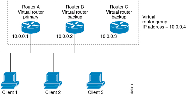
Because the virtual IP address uses the IP address of the physical Ethernet interface of Router A, Router A is the primary (also known as the IP address owner). As the primary, Router A owns the virtual IP address of the VRRP group router and forwards packets that are sent to this IP address. Clients 1 through 3 are configured with the default gateway IP address of 10.0.0.1.

Routers B and C function as backups. If the primary fails, the backup router with the highest priority becomes the primary and takes over the virtual IP address to provide uninterrupted service for the LAN hosts. When router A recovers, it becomes the router primary again. For more information, see the “VRRP Router Priority and Preemption” section.


Note


Packets that are received on a routed port that is destined for the VRRP virtual IP address terminate on the local router, regardless of whether that router is the primary VRRP router or a backup VRRP router. This includes ping and telnet traffic. Packets received on a Layer 2 (VLAN) interface destined for the VRRP virtual IP address will terminate on the primary router.


VRRP Benefits

The benefits of VRRP are as follows:

  • Redundance—Enables you to configure multiple routers as the default gateway router, which reduces the possibility of a single point of failure in a network.

  • Load Sharing—Allows traffic to and from LAN clients to be shared by multiple routers. The traffic load is shared more equitably among available routers.

  • Multiple VRRP groups—Supports up to 255 VRRP groups on a router physical interface if the platform supports multiple MAC addresses. Multiple VRRP groups enable you to implement redundancy and load sharing in your LAN topology.

  • Multiple IP Addresses—Allows you to manage multiple IP addresses, including secondary IP addresses. If you have multiple subnets that are configured on an Ethernet interface, you can configure VRRP on each subnet.

  • Preemption—Enables you to preempt a backup router that has taken over for a failing primary with a higher priority backup router that has become available.

  • Advertisement Protocol—Uses a dedicated Internet Assigned Numbers Authority (IANA) standard multicast address (224.0.0.18) for VRRP advertisements. This addressing scheme minimizes the number of routers that must service the multicasts and allows test equipment to accurately identify VRRP packets on a segment. IANA has assigned the IP protocol number 112 to VRRP.

  • The benefits of VRRPv3 are as follows:

    • Interoperability in multivendor environments.

    • Support for the IPv4 and IPv6 address families.

Multiple VRRP Groups

You can configure up to 255 VRRP groups on a physical interface. The actual number of VRRP groups that a router interface can support depends on the following factors:

  • Router processing capability

  • Router memory capability

In a topology where multiple VRRP groups are configured on a router interface, the interface can act as a primary for one VRRP group and as a backup for one or more other VRRP groups.

The following figure shows a LAN topology in which VRRP is configured so that Routers A and B share the traffic to and from clients 1 through 4. Routers A and B act as backups to each other if either router fails.

Figure 2. Load Sharing and Redundancy VRRP Topology

This topology contains two virtual IP addresses for two VRRP groups that overlap. For VRRP group 1, Router A is the owner of IP address 10.0.0.1 and is the primary. Router B is the backup to router A. Clients 1 and 2 are configured with the default gateway IP address of 10.0.0.1.

For VRRP group 2, Router B is the owner of IP address 10.0.0.2 and is the primary. Router A is the backup to router B. Clients 3 and 4 are configured with the default gateway IP address of 10.0.0.2.

VRRP Router Priority and Preemption

An important aspect of the VRRP redundancy scheme is the VRRP router priority because the priority determines the role that each VRRP router plays and what happens if the primary router fails.

If a VRRP router owns the virtual IP address and the IP address of the physical interface, this router functions as the primary. The priority of the primary is 255.

Priority also determines if a VRRP router functions as a backup router and the order of ascendancy to becoming a primary if the primary fails.

For example, if router A, the primary in a LAN topology fails, VRRP must determine if backups B or C should take over. If you configure router B with priority 101 and router C with the default priority of 100, VRRP selects router B to become the primary because it has the higher priority. If you configure routers B and C with the default priority of 100, VRRP selects the backup with the higher IP address to become the primary.

VRRP uses preemption to determine what happens after a VRRP backup router becomes the primary. With preemption enabled by default, VRRP switches to a backup if that backup comes online with a priority higher than the new primary. For example, if Router A is the primary and fails, VRRP selects Router B (next in order of priority). If Router C comes online with a higher priority than Router B, VRRP selects Router C as the new primary, even though Router B has not failed.

If you disable preemption, VRRP will only switch if the original primary recovers or the new primary fails.

VRRP Advertisements

The VRRP primary sends VRRP advertisements to other VRRP routers in the same group. The advertisements communicate the priority and state of the primary. Cisco NX-OS encapsulates the VRRP advertisements in IP packets and sends them to the IP multicast address assigned to the VRRP group. Cisco NX-OS sends the advertisements once every second by default, but you can configure a different advertisement interval.

VRRP Authentication

VRRP supports the following authentication mechanisms:

  • No authentication

  • Plain text authentication

VRRP rejects packets in any of the following cases:

  • The authentication schemes differ on the router and in the incoming packet.

  • Text authentication strings differ on the router and in the incoming packet.

VRRPv3

VRRP version 3 (VRRPv3) enables a group of switches to form a single virtual switch in order to provide redundancy and reduce the possibility of a single point of failure in a network. The LAN clients can then be configured with the virtual switch as their default gateway. The virtual switch, representing a group of switches, is also known as a VRRPv3 group.

Virtualization Support

VRRP supports Virtual Routing and Forwarding instances (VRFs). By default, Cisco NX-OS places you in the default VRF unless you specifically configure another VRF.

If you change the VRF membership of an interface, Cisco NX-OS removes all Layer 3 configuration, including VRRP.

For more information, see Configuring Layer 3 Virtualization.

Guidelines and Limitations for VRRP

VRRP has the following configuration guidelines and limitations:

  • You cannot configure VRRP on the management interface.

  • When VRRP is enabled, you should replicate the VRRP configuration across switches in your network.

  • If you want to perform a graceful failover of the VRRPv3 peer, shut down the protocol first and then shut down the interface. Shutting down the interface does not guarantee a quick transition between the peers before the interface shuts down. Therefore, it can result in a VRRPv3 failover based on the expiry of the hold time.

  • We recommend that you do not configure more than one first-hop redundancy protocol on the same interface.

  • You must configure an IP address for the interface that you configure VRRP on and enable that interface before VRRP becomes active.

  • Cisco NX-OS removes all Layer 3 configurations on an interface when you change the interface VRF membership, port channel membership, or when you change the port mode to Layer 2.

  • When you configure VRRP to track a Layer 2 interface, you must shut down the Layer 2 interface and reenable the interface to update the VRRP priority to reflect the state of the Layer 2 interface.

  • VRRPv3 has the following configuration guidelines and limitations:

    • VRRPv3 is not intended as a replacement for existing dynamic protocols. VRRPv3 is designed for use over multi-access, multicast, or broadcast-capable Ethernet LANs.

    • VRRPv3 is supported only on Ethernet and Fast Ethernet interfaces, bridge group virtual interfaces (BVIs), and Gigabit Ethernet interfaces as well as on Multiprotocol Label Switching (MPLS) virtual private networks (VPNs), VRF-aware MPLS VPNs, and VLANs.

    • When VRRPv3 is in use, VRRPv2 is unavailable. To configure VRRPv3, you must disable any VRRPv2 configuration.

    • Use VRRPv3 millisecond timers only where absolutely necessary and with careful consideration and testing. Millisecond values work only under favorable circumstances. The millisecond timer values are compatible with third-party vendors, as long as they also support VRRPv3.

Default Settings for VRRP

Table below lists the default settings for VRRP parameters.

Table 1. Default VRRP Parameters

Parameters

Default

advertisement interval

1 seconds

authentication

no authentication

preemption

enabled

priority

100

VRRP feature

disabled

VRRPv3

disabled

VRRPv3 secondary address matchin

Enabled

VRRPv3 timers advertise

1000 milliseconds

Configuring VRRP

Enabling the VRRP Feature

You must globally enable the VRRP feature before you can configure and enable any VRRP groups.

To enable the VRRP feature, use the following command in global configuration mode:

Command

Purpose

feature vrrp

Example :

switch(config)# feature vrrp

Enables VRRP.

To disable the VRRP feature and remove all associated configuration, use the following command in global configuration mode:

Command

Purpose

no feature vrrp

Example :

switch(config)# no feature vrrp

Disables the VRRP feature.

Configuring VRRP Groups

You can create a VRRP group, assign the virtual IP address, and enable the group.

You can configure one virtual IPv4 address for a VRRP group. By default, the primary VRRP router drops the packets addressed directly to the virtual IP address because the VRRP primary is only intended as a next-hop router to forward packets. Some applications require that Cisco NX-OS accept packets that are addressed to the virtual router IP. Use the secondary option to the virtual IP address to accept these packets when the local router is the VRRP primary.

Once you have configured the VRRP group, you must explicitly enable the group before it becomes active.

Before you begin

Ensure that you configure an IP address on the interface (see the Configuring IPv4 Addressing section).

SUMMARY STEPS

  1. configure terminal
  2. interface interface -type slot/port
  3. no switchport
  4. vrrp number
  5. address ip-address [ secondary ]
  6. no shutdown
  7. (Optional) show vrrp
  8. (Optional) copy running-config startup-config

DETAILED STEPS

  Command or Action Purpose

Step 1

configure terminal

Example:

switch# configure terminal
switch(config)#

Enters configuration mode.

Step 2

interface interface -type slot/port

Example:

switch(config)#
switch(config-if)# interface ethernet 2/1

Enters interface configuration mode.

Step 3

no switchport

Example:

switch(config-if)# no switchport

Configures the interface as a Layer 3 routed interface.

Step 4

vrrp number

Example:

switch(config-if)# vrrp 250
switch(config-if-vrrp)#

Creates a virtual router group. The range is 1–255.

Step 5

address ip-address [ secondary ]

Example:

switch(config-if-vrrp)# address 192.0.2.8

Configures the virtual IPv4 address for the specified VRRP group. This address should be in the same subnet as the IPv4 address of the interface.

Use the secondary option only if applications require that VRRP routers accept the packets sent to the virtual router’s IP address and deliver to applications.

Step 6

no shutdown

Example:

switch(config-if-vrrp)# no shutdown
switch(config-if-vrrp)#

Enables the VRRP group. Disabled by default.

Step 7

(Optional) show vrrp

Example:

switch(config-if-vrrp)# show vrrp
(Optional)

Displays VRRP information.

Step 8

(Optional) copy running-config startup-config

Example:

switch(config-if-vrrp)# copy running-config startup-config
(Optional)

Saves this configuration change.

Configuring VRRP Priority

The valid priority range for a virtual router is 1–254 (1 is the lowest priority and 254 is the highest). The default priority value for backups is 100. For switches whose interface IP address is the same as the primary virtual IP address (the primary), the default value is 255.

Before you begin

Ensure that you have enabled the VRRP feature (see the Configuring VRRP section).

Ensure that you have configured an IP address on the interface (see the Configuring IPv4 Addressing section.

SUMMARY STEPS

  1. configure terminal
  2. interface interface -type slot/port
  3. no switchport
  4. vrrp number
  5. shutdown
  6. priority level [ forwarding-threshold lower lower-value upper upper-value ]
  7. no shutdown
  8. (Optional) show vrrp
  9. (Optional) copy running-config startup-config

DETAILED STEPS

  Command or Action Purpose

Step 1

configure terminal

Example:

switch# configure terminal
switch(config)#

Enters configuration mode.

Step 2

interface interface -type slot/port

Example:

switch(config)#
switch(config-if)# interface ethernet 2/1

Enters interface configuration mode.

Step 3

no switchport

Example:

switch(config-if)# no switchport

Configures the interface as a Layer 3 routed interface.

Step 4

vrrp number

Example:

switch(config-if)# vrrp 250
switch(config-if-vrrp)#

Creates a virtual router group. The range is 1–255.

Step 5

shutdown

Example:

switch(config-if-vrrp)# shutdown
switch(config-if-vrrp)#

Disables the VRRP group. Disabled by default.

Step 6

priority level [ forwarding-threshold lower lower-value upper upper-value ]

Example:

switch(config-if-vrrp)# priority 60 forwarding-threshold lower 40 upper 50

Sets the priority level used to select the active router in an VRRP group. The level range is 1–254. The default is 100 for backups and 255 for a primary that has an interface IP address equal to the virtual IP address.

Step 7

no shutdown

Example:

switch(config-if-vrrp)# no shutdown
switch(config-if-vrrp)#

Enables the VRRP group. Disabled by default.

Step 8

(Optional) show vrrp

Example:

switch(config-if-vrrp)# show vrrp
(Optional)

Displays VRRP information.

Step 9

(Optional) copy running-config startup-config

Example:

switch(config-if-vrrp)# copy running-config startup-config
(Optional)

Saves this configuration change.

Configuring VRRP Authentication

You can configure simple text authentication for a VRRP group.

Before you begin

Ensure that the authentication configuration is identical for all VRRP switches in the network.

Ensure that you have enabled the VRRP feature (see the Configuring VRRP section).

Ensure that you have configured an IP address on the interface (see the Configuring IPv4 Addressing section.

SUMMARY STEPS

  1. configure terminal
  2. interface interface -type slot/port
  3. no switchport
  4. vrrp number
  5. shutdown
  6. authentication text password
  7. no shutdown
  8. (Optional) show vrrp
  9. (Optional) copy running-config startup-config

DETAILED STEPS

  Command or Action Purpose

Step 1

configure terminal

Example:

switch# configure terminal
switch(config)#

Enters configuration mode.

Step 2

interface interface -type slot/port

Example:

switch(config)#
switch(config-if)# interface ethernet 2/1

Enters interface configuration mode.

Step 3

no switchport

Example:

switch(config-if)# no switchport

Configures the interface as a Layer 3 routed interface.

Step 4

vrrp number

Example:

switch(config-if)# vrrp 250
switch(config-if-vrrp)#

Creates a virtual router group. The range is from 1 to 255.

Step 5

shutdown

Example:

switch(config-if-vrrp)# shutdown
switch(config-if-vrrp)#

Disables the VRRP group. Disabled by default.

Step 6

authentication text password

Example:

switch(config-if-vrrp)# authentication text cisco123

Assigns the simple text authentication option and specifies the keyname password. The keyname range is from 1 to 255 characters. We recommend that you use at least 16 characters. The text password is up to eight alphanumeric characters.

Step 7

no shutdown

Example:

switch(config-if-vrrp)# no shutdown
switch(config-if-vrrp)#

Enables the VRRP group. Disabled by default.

Step 8

(Optional) show vrrp

Example:

switch(config-if-vrrp)# show vrrp
(Optional)

Displays VRRP information.

Step 9

(Optional) copy running-config startup-config

Example:

switch(config-if-vrrp)# copy running-config startup-config
(Optional)

Saves this configuration change.

Example

Configuring Time Intervals for Advertisement Packets

You can configure the time intervals for advertisement packets.

Before you begin

Ensure that you have enabled the VRRP feature (see the Configuring VRRP section).

Ensure that you have configured an IP address on the interface (see the Configuring IPv4 Addressing section.

SUMMARY STEPS

  1. configure terminal
  2. interface interface -type slot/port
  3. no switchport
  4. vrrp number
  5. shutdown
  6. advertisement-interval seconds
  7. no shutdown
  8. (Optional) show vrrp
  9. (Optional) copy running-config startup-config

DETAILED STEPS

  Command or Action Purpose

Step 1

configure terminal

Example:

switch# configure terminal
switch(config)#

Enters configuration mode.

Step 2

interface interface -type slot/port

Example:

switch(config)#
switch(config-if)# interface ethernet 2/1

Enters interface configuration mode.

Step 3

no switchport

Example:

switch(config-if)# no switchport

Configures the interface as a Layer 3 routed interface.

Step 4

vrrp number

Example:

switch(config-if)# vrrp 250
switch(config-if-vrrp)#

Creates a virtual router group. The range is from 1 to 255.

Step 5

shutdown

Example:

switch(config-if-vrrp)# shutdown
switch(config-if-vrrp)#

Disables the VRRP group. Disabled by default.

Step 6

advertisement-interval seconds

Example:

switch(config-if-vrrp)# advertisement-interval 15

Sets the interval time in seconds between sending advertisement frames. The range is from 1 to 254. The default is 1 second.

Step 7

no shutdown

Example:

switch(config-if-vrrp)# no shutdown
switch(config-if-vrrp)#

Enables the VRRP group. Disabled by default.

Step 8

(Optional) show vrrp

Example:

switch(config-if-vrrp)# show vrrp
(Optional)

Displays VRRP information.

Step 9

(Optional) copy running-config startup-config

Example:

switch(config-if-vrrp)# copy running-config startup-config
(Optional)

Saves this configuration change.

Example

Disabling Preemption

You can disable preemption for a VRRP group member. If you disable preemption, a higher-priority backup router will not take over for a lower-priority primary router. Preemption is enabled by default.

Before you begin

Ensure that you have enabled the VRRP feature (see the Configuring VRRP section).

Ensure that you have configured an IP address on the interface (see the Configuring IPv4 Addressing section.

SUMMARY STEPS

  1. configure terminal
  2. interface interface -type slot/port
  3. no switchport
  4. vrrp number
  5. shutdown
  6. no preempt
  7. no shutdown
  8. (Optional) show vrrp
  9. (Optional) copy running-config startup-config

DETAILED STEPS

  Command or Action Purpose

Step 1

configure terminal

Example:

switch# configure terminal
switch(config)#

Enters configuration mode.

Step 2

interface interface -type slot/port

Example:

switch(config)#
switch(config-if)# interface ethernet 2/1

Enters interface configuration mode.

Step 3

no switchport

Example:

switch(config-if)# no switchport

Configures the interface as a Layer 3 routed interface.

Step 4

vrrp number

Example:

switch(config-if)# vrrp 250
switch(config-if-vrrp)#

Creates a virtual router group. The range is 1–255.

Step 5

shutdown

Example:

switch(config-if-vrrp)# shutdown
switch(config-if-vrrp)#

Disables the VRRP group. Disabled by default.

Step 6

no preempt

Example:

switch(config-if-vrrp)# no preempt

Disables the preempt option and allows the primary to remain when a higher-priority backup appears.

Step 7

no shutdown

Example:

switch(config-if-vrrp)# no shutdown
switch(config-if-vrrp)#

Enables the VRRP group. Disabled by default.

Step 8

(Optional) show vrrp

Example:

switch(config-if-vrrp)# show vrrp
(Optional)

Displays VRRP information.

Step 9

(Optional) copy running-config startup-config

Example:

switch(config-if-vrrp)# copy running-config startup-config
(Optional)

Saves this configuration change.

Configuring VRRP Interface State Tracking

Interface state tracking changes the priority of the virtual router based on the state of another interface in the switch. When the tracked interface goes down or the IP address is removed, Cisco NX-OS assigns the tracking priority value to the virtual router. When the tracked interface comes up and an IP address is configured on this interface, Cisco NX-OS restores the configured priority to the virtual router (see the Configuring VRRP Priority section).


Note


For interface state tracking to function, you must enable preemption on the interface.


Note


VRRP does not support Layer 2 interface tracking.


Before you begin

Ensure that you have enabled the VRRP feature (see the Configuring VRRP section).

Ensure that you have configured an IP address on the interface (see the Configuring IPv4 Addressing section.

Be sure the virtual router is enabled (see the Configuring VRRP Groups section).

SUMMARY STEPS

  1. configure terminal
  2. interface interface -type slot/port
  3. no switchport
  4. vrrp number
  5. shutdown
  6. track interface type number priority value
  7. no shutdown
  8. (Optional) show vrrp
  9. (Optional) copy running-config startup-config

DETAILED STEPS

  Command or Action Purpose

Step 1

configure terminal

Example:

switch# configure terminal
switch(config)#

Enters configuration mode.

Step 2

interface interface -type slot/port

Example:

switch(config)#
switch(config-if)# interface ethernet 2/1

Enters interface configuration mode.

Step 3

no switchport

Example:

switch(config-if)# no switchport

Configures the interface as a Layer 3 routed interface.

Step 4

vrrp number

Example:

switch(config-if)# vrrp 250
switch(config-if-vrrp)#

Creates a virtual router group. The range is from 1 to 255.

Step 5

shutdown

Example:

switch(config-if-vrrp)# shutdown
switch(config-if-vrrp)#

Disables the VRRP group. Disabled by default.

Step 6

track interface type number priority value

Example:

switch(config-if-vrrp)# track interface ethernet 2/10 priority 254

Enables interface priority tracking for a VRRP group. The priority range is from 1 to 254.

Step 7

no shutdown

Example:

switch(config-if-vrrp)# no shutdown
switch(config-if-vrrp)#

Enables the VRRP group. Disabled by default.

Step 8

(Optional) show vrrp

Example:

switch(config-if-vrrp)# show vrrp
(Optional)

Displays VRRP information.

Step 9

(Optional) copy running-config startup-config

Example:

switch(config-if-vrrp)# copy running-config startup-config
(Optional)

Saves this configuration change.

Configuring VRRPv3

Enabling VRRPv3

You must globally enable the VRRPv3 feature before you can configure and enable any VRRPv3 groups.

To enable the VRRPv3 feature, use the following command in global configuration mode:

Command

Purpose

feature vrrpv3

Example :

switch(config)# feature vrrpv3

Enables VRRP version 3. The no form of this command disables VRRPv3 in a VDC.

If VRRPv2 is currently configured, use the no feature vrrp command in global configuration mode to remove the VRRPv2 configuration and then use the feature vrrpv3 command to enable VRRPv3.

Configuring VRRPv3 Groups

You can create a VRRPv3 group, assign the virtual IP address, and enable the group.

You can configure one virtual IPv4 address for a VRRPv3 group. By default, the primary VRRPv3 router drops the packets addressed directly to the virtual IP address because the VRRPv3 primary is only intended as a next-hop router to forward packets. Some applications require that Cisco NX-OS accept packets that are addressed to the virtual router IP. Use the secondary option to the virtual IP address to accept these packets when the local router is the VRRPv3 primary.


Note


After you have configured the VRRPv3 group, you must explicitly enable the group before it becomes active.


Before you begin

  • Ensure that the VRRPv3 feature is enabled.

  • Ensure that you configure an IP address on the interface.

SUMMARY STEPS

  1. configure terminal
  2. interface interface -type slot/port
  3. [no] vrrpv3 number address-family { ipv4 | ipv6 }
  4. (Optional) [no] address ip-address [ primary | secondary ]
  5. (Optional) [no] description description
  6. (Optional) [no] match-address
  7. (Optional) [no] preempt [ delay minimum seconds ]
  8. (Optional) [no] priority level
  9. (Optional) [no] timers advertise interval
  10. [no] vrrpv2
  11. (Optional) [no] shutdown
  12. (Optional) show fhrp [ interface-type interface-number ] [verbose]
  13. (Optional) copy running-config startup-config

DETAILED STEPS

  Command or Action Purpose

Step 1

configure terminal

Example:

switch# configure terminal
switch(config)#

Enters global configuration mode.

Step 2

interface interface -type slot/port

Example:

switch(config)# interface ethernet 2/1
switch(config-if)#

Enters interface configuration mode.

Step 3

[no] vrrpv3 number address-family { ipv4 | ipv6 }

Example:

switch(config-if)# vrrpv3 5 address-family

ipv4

switch(config-if-vrrpv3-group)#

Creates a VRRPv3 group and enters VRRPv3 group configuration mode. The range is 1–255.

The no form of this command removes all configuration that is defined within the submode.

Step 4

(Optional) [no] address ip-address [ primary | secondary ]

Example:

switch(config-if-vrrpv3-group)# address

100.0.1.10 primary
(Optional)

Specifies a primary or secondary IPv4 or IPv6 address for the VRRPv3 group.

Note


To utilize secondary IP addresses in a VRRPv3 group, you must first configure a primary IP address on the same group.

Step 5

(Optional) [no] description description

Example:

switch(config-if-vrrpv3-group)# description

group3
(Optional)

Specifies a description for the VRRPv3 group. You can enter up to 80 alphanumeric characters.

Step 6

(Optional) [no] match-address

Example:

switch(config-if-vrrpv3-group)# match-address
(Optional)

Matches the secondary address in the advertisement packet against the configured address.

Step 7

(Optional) [no] preempt [ delay minimum seconds ]

Example:

switch(config-if-vrrpv3-group)# preempt
delay minimum 30
(Optional)

Enables preemption of a lower priority primary switch with an optional delay. The range is 0–3600.

Step 8

(Optional) [no] priority level

Example:

switch(config-if-vrrpv3-group)# priority 3
(Optional)

Specifies the priority of the VRRPv3 group. The range is 1–254.

Step 9

(Optional) [no] timers advertise interval

Example:

switch(config-if-vrrpv3-group)# timers advertise 1000
(Optional)

Sets the advertisement timer in milliseconds. The range is 100–40950.

Note


Cisco recommends that you set this timer to a value greater than or equal to 1 second.

Step 10

[no] vrrpv2

Example:

switch(config-if-vrrpv3-group)# vrrpv2

Enables support for VRRPv2 simultaneously, to ensure interoperability with devices that support only VRRPv2.

Note


VRRPv2 compatibility mode is provided to allow an upgrade from VRRPv2 to VRRPv3. This is not a full VRRPv2 implementation and should be used only to perform an upgrade.

Step 11

(Optional) [no] shutdown

Example:

switch(config-if-vrrp3-group)# shutdown
(Optional)

Disables VRRP configuration for the VRRPv3 group.

Step 12

(Optional) show fhrp [ interface-type interface-number ] [verbose]

Example:

switch(config-if-vrrp3-group)# show fhrp port-channnel 101 verbose
(Optional)

Displays First Hop Redundancy Protocol (FHRP) information.

Use the verbose keyword to view detailed information.

Step 13

(Optional) copy running-config startup-config

Example:

switch(config-if-vrrp3-group)# copy running-config startup-config
(Optional)

Saves this configuration change.

Configuring the Delay Period for FHRP Client Initialization

You can configure the delay period for the initialization of FHRP clients.


Note


In all FHRP protocols, we do not recommend to use aggressive timers as they cause CPU spikes and they result in increased control packet flow. In case of VRRPv3, you should configure sufficient interface delay/reload delay for proper failover of the VRRP nodes.


To configure this feature, use the following command in interface configuration mode:

Command

Purpose

fhrp delay {[ minimum ] | [reload ] seconds }

Example :

switch(config)# fhrp delay minimum 34

Specifies the delay period for the initialization of FHRP clients. The range is from 0 to 3600 seconds.

The minimum keyword configures the delay period after an interface becomes available.

The reload command configures the delay period after the device reloads.

Configuring VRRPv3 Control Groups

You can configure a VRRPv3 control group.

Before you begin

  • Ensure that the VRRPv3 feature is enabled.

  • Ensure that you configure an IP address on the interface.

SUMMARY STEPS

  1. configure terminal
  2. interface interface - type slot/port
  3. [no] ip address ip-address mask [ secondary]
  4. [no] vrrpv3 number address-family { ipv4 | ipv6 }
  5. (Optional) [no] address ip-address [ primary | secondary ]
  6. (Optional) [no] shutdown
  7. [ show fhrp [ interface-type interface-number ] [verbose]
  8. copy running-config startup-config

DETAILED STEPS

  Command or Action Purpose

Step 1

configure terminal

Example:

switch# configure terminal
switch(config)#

Enters global configuration mode.

Step 2

interface interface - type slot/port

Example:

switch(config)# interface ethernet 2/1
switch(config-if)#

Enters interface configuration mode.

Step 3

[no] ip address ip-address mask [ secondary]

Example:

switch(config-if)# ip address 209.165.200.230 255.255.255.224

Configures the IP address on the interface.

Note


You can use the secondary keyword to configure additional IP addresses on the interface.

Step 4

[no] vrrpv3 number address-family { ipv4 | ipv6 }

Example:

switch(config-if)# vrrpv3 5 address-family
ipv4
switch(config-if-vrrpv3-group)#

Creates a VRRPv3 group and enters VRRPv3 group configuration mode. The range is from 1 to 255.

Step 5

(Optional) [no] address ip-address [ primary | secondary ]

Example:

switch(config-if-vrrpv3-group)# address
209.165.200.227 primary
(Optional)

Specifies a primary or secondary IPv4 or IPv6 address for the VRRPv3 group.

Step 6

(Optional) [no] shutdown

Example:

switch(config-if-vrrp3-group)# shutdown
(Optional)

Disables VRRP configuration for the VRRPv3 group.

Step 7

[ show fhrp [ interface-type interface-number ] [verbose]

Example:

switch(config-if-vrrp3-group)# show fhrp port-channnel 101 verbose

Displays First Hop Redundancy Protocol (FHRP) information.

Use the verbose keyword to view detailed information.

Step 8

copy running-config startup-config

Example:

switch(config-if-vrrp3-group)# copy running-config startup-config

Saves this configuration change.

Verifying the VRRPv2 Configuration

To display the VRRPv2 configuration information, perform one of the following tasks:

Command

Purpose

show vrrpv2

Displays the VRRP status for all groups.

show vrrpv2 vr group-number

Displays the VRRP status for a VRRP group.

show vrrp v2 vr number interface interface-type port configuration

Displays the virtual router configuration for an interface.

show vrrpv2 vr number interface interface-type portstatus

Displays the virtual router status for an interface.

show fhrp [ interface-type interface-number] [verbose]

Displays First Hop Redundancy Protocol (FHRP) information.

show interface interface-type

Displays the virtual router configuration for an interface.

Verifying the VRRPv3 Configuration

See the following table for information on the fields in the show vrrpv3 command output:

Command

Purpose

>

Redirect it to a file

>>

Redirect it to a file in append mode

all

All VRRPV3 information

brief

Brief output

detail

Detail output

ethernet

Ethernet IEEE 802.3z

ipv4

IPv4

ipv6

IPv6

loopback

Loopback interface

port-channel

Port-channel interface

statistics

Statistics output

vlan

VLAN interface

|

Pipe command output to filter

For example, use the show vrrpv3 statistics command to display the VRRPv3 statistics.

Displaying VRRP Statistics

To display VRRP statistics, use the following commands:

Command

Purpose

show vrrp statistics interface interface-type port vr number

Displays the virtual router information.

show vrrp statistics

Displays the VRRP statistics.

Use the clear vrrp vr command to clear the IPv4 VRRP statistics for a specified interface.

Use the clear vrrp ipv4 command to clear all the statistics for the specified IPv4 virtual router.

Configuration Examples for VRRPv2

In this example, Router A and Router B each belong to three VRRP groups. In the configuration, each group has the following properties:

  • Group 1:

    • Virtual IP address is 10.1.0.10.

    • Router A becomes the primary for this group with priority 120.

    • Advertising interval is 3 seconds.

    • Preemption is enabled.

  • Group 5:

    • Router B becomes the primary for this group with priority 200.

    • Advertising interval is 30 seconds.

    • Preemption is enabled.

  • Group 100:

    • Router A becomes the primary for this group first because it has a higher IP address (10.1.0.2).

    • Advertising interval is the default 1 second.

    • Preemption is disabled.

Router A

interface ethernet 1/0
no switchport

ip address 10.1.0.2/16
no shutdown
vrrpv2 1
priority 120
authentication text cisco
advertisement-interval 3
address 10.1.0.10
no shutdown
vrrpv2 5
priority 100
advertisement-interval 30
address 10.1.0.50
no shutdown
vrrpv2 100
no preempt
address 10.1.0.100
no shutdown
 

Router B

interface ethernet 1/0
no switchport

ip address 10.2.0.1/2
no shutdown
vrrpv2 1
priority 100
authentication text cisco
advertisement-interval 3
address 10.2.0.10
no shutdown
 
vrrpv2 5
priority 200
advertisement-interval 30
address 10.2.0.50
no shutdown
vrrpv2 100
no preempt
address 10.2.0.100
no shutdown

Configuration Example for VRRPv3

See the following configuration example for VRRPv3.

interface Vlan20
vrrpv3 10 address-family ipv4
timers advertise 1000
priority 100
preempt
match-address
no vrrpv2
address 20.1.1.1 primary
address 20.1.1.5 secondary
vrrpv3 10 address-family ipv6
timers advertise 1000
priority 100
preempt
match-address
no vrrpv2
address fe80::1 primary
address 2011::5

Additional References

For additional information related to implementing VRRP, see the following sections:

Related Documents

Related Topic

Document Title

Configuring the Hot Standby Routing Protocol

Configuring HSRP