About Cisco 1100 Terminal Gateway Routers

Cisco 1100 Terminal Gateway Routers are terminal servers that provides asynchronous connections to the console ports for Cisco devices.

Table 1. Base Models of the Cisco 1100 Terminal Gateway Routers

Base Models

Asynchronous Ports

NIM Slot

Switch

Memory

C1100TG-1N32A

32

Yes

None

2GB Dram/ 4GB flash

C1100TG-1N24P32A

32

Yes

24 port L2 Switch

4GB Dram/ 4GB flash

C1100TGX-1N24P32A

32

Yes

24 port L2 Switch

8GB Dram/ 8GB flash

For more information on the features and specifications of Cisco 1100 Series Terminal Gateway Routers, refer to Cisco 1100 Terminal Gateway Routers datasheet.

Chassis Views

This section contains front and back panel views of the Cisco 1100 Terminal Gateway Routers-showing locations of the power and signal interfaces, interface slots, status indicators, and chassis identification labels.

Figure 1. C1100TG-1N32A - I/O View

1

System LED

2

USB 2.0

3

GE WAN 0/0/0 - RJ45/SFP

4

GE WAN 0/0/1 – RJ45/SFP

5

ASYNC 16 port

6

ASYNC 32 port

7

NIM

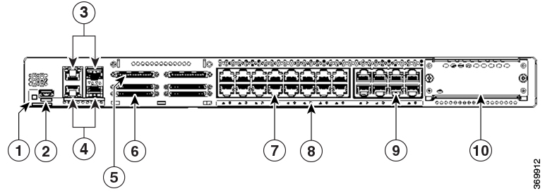
Figure 2. C1100TG-1N24P32A and C1100TGX-1N24P32A - I/O View

1

System LED

2

USB 2.0

3

GE WAN 0/0/0 - RJ45/SFP

4

GE WAN 0/0/1 – RJ45/SFP

5

ASYNC 16 port

6

ASYNC 32 port

7

Ethernet Switch 0-15

8

Ethernet Switch LED 0-23

9

Ethernet Switch 16-23

10

NIM

Figure 3. C1100TG-1N32A - Rear View

1

USB 3.0

2

6-pin Power Connector

3

RJ-45 Console, AUX

4

ASYNC LED

5

Grounding Attachment

6

Power Supply

Figure 4. C1100TG-1N24P32A and C1100TGX-1N24P32A - Rear View

1

USB 3.0

2

6-pin Power Connector

3

RJ-45 Console, AUX

4

ASYNC LED

5

Grounding Attachment

6

Power Supply

LED Indicators

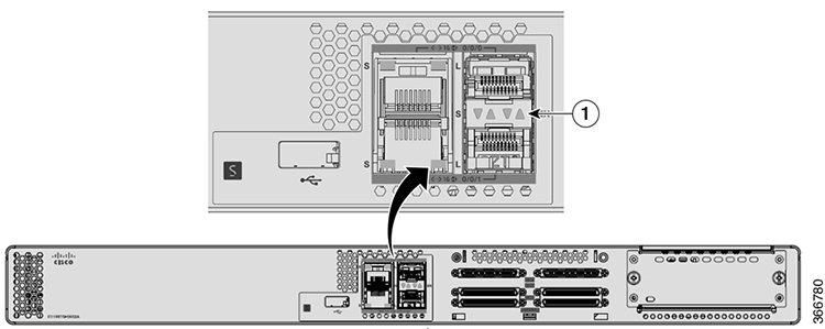
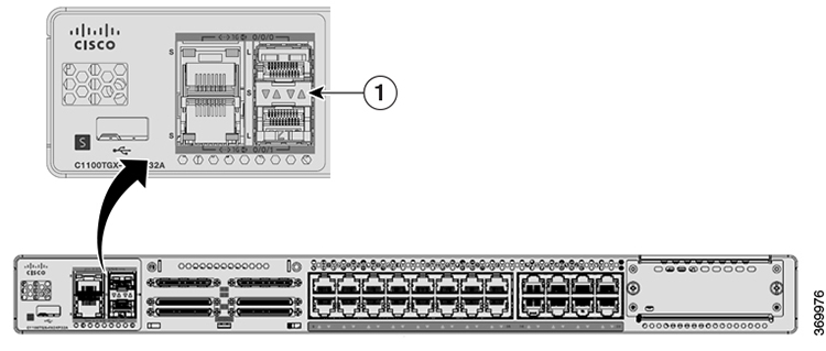
The following figures and table summarizes the LED indicators that are located on the chassis of the Cisco 1100 Terminal Gateway Routers.

Figure 5. LED Indicators - C1100TG-1N32A I/O Side
Figure 6. LED Indicators - C1100TG-1N24P32A and C1100TGX-1N24P32A I/O Side

Table 2. LED Indicators for Cisco Cisco 1100 Terminal Gateway Router

Port

LED Color

Description

Control Source

System LEDs

Green and Amber

Off—Systempower off

Bezel side. All models.

Steady Green - System operates normally.

Blinking Green — BIOS/Rommon is booting.

Steady Amber — Thermal trip.

Blinking Amber – Alarm, Secure boot failure.

LAN Port LEDs

Green

Off— No link

Bezel Side

Steady On— Link

Blink - TXD/RXD Data

WAN Port LEDs

Green and Amber

Green - Indicates SFP module detected

Bezel Side

Amber - Indicates SFP is not detected or at fault

ASYNC Port LEDs

Green

link established

Rear side

Power Supply

The product power specifications are as follows:

  • AC input voltage: 100 to 240 VAC, 1.6 A, 50-60 Hz

  • DC input voltage: 48 to 60 VDC or -48 to -60 VDC, 4.2 A

  • External power supply option: 100 to 240 VAC, 50 - 60 Hz

  • HVDC power supply: 240 VDC, 0.9 A

Slots and Interfaces

About Slots, Subslots, and Port Numbering

The following figure shows slots and subslots numbering for C1100TG-1N32A:

Figure 7. C1100TG-1N32A: Slots and Subslots

1

Slot 0/0 Front panel Gigabit Ethernet

2

RJ45/SFP combo GigaEthernet 0/0/0

3

Slot 0/1 onboard Async serial

1 = 0-7

2 = 8-15

3 = 16-23

4 = 24-31

5 = 32-39

6 = 40-47

Async 0/1/0 ~ Async 0/1/47

4

Slot 0/2 NIM slot

5

RJ45/SFP combo GigaEthernet 0/0/1

Figure 8. C1100TG-1N24P32A and C1100TGX-1N24P32A: Slots and Subslots

1

Slot 0/0 Front panel Gigabit Ethernet

2

RJ45/SFP combo GigaEthernet 0/0/0

3

Slot 0/1 onboard Async serial

1 = 0-7

2 = 8-15

3 = 16-23

4 = 24-31

5 = 32-39

6 = 40-47

Async 0/1/0 ~ Async 0/1/47

4

LAN 0

5

Slot 0/2 Onboard L2 switch GigaEthernet 0/2/0 ~ GigaEthernet 0/2/23

6

LAN 22

7

Slot 0/3 NIM slot

8

LAN 23

9

LAN 1

10

RJ45/SFP combo GigaEthernet 0/0/1

Async line Numbering

Cisco 1100 Terminal Gateway Routers has 32 onboard async ports, line number starts at 2 and ends at 33. An optional Daughter Card with 16 async ports can be added to Nanook base and Nanook+, line number for Daughter Card starts at 33 and ends at 49.

Figure 9. C1100TG-1N32A: Line Numbering

1

GigaEthernet 0/0/0 to 0/0/1

2

Async 0/1/0 to Async 0/1/47

0 = 2-9

1 = 10-17

2 = 18-25

3 = 26-33

4 = 34-41

5 = 42-49

3

NIM 0/2

Figure 10. C1100TG-1N24P32A and C1100TGX-1N24P32A: Line Numbering

1

GigaEthernet 0/0/0 to 0/0/1

2

Async 0/1/0 to Async 0/1/47

0 = 2-9

1 = 10-17

2 = 18-25

3 = 26-33

4 = 34-41

5 = 42-49

3

GigaEthernet 0/2/0 to 0/2/23

4

NIM 0/3

Fans, Ventilation and Airflow

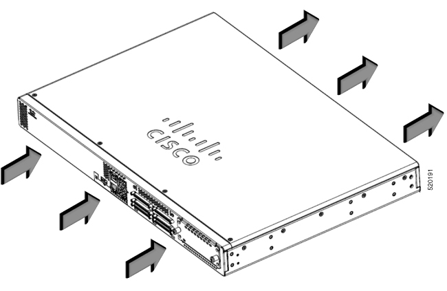
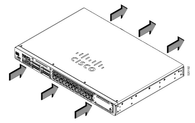
Router and chassis temperature is regulated with internal fans. An onboard temperature sensor controls the fan speed. The fans are always on when the router is powered on. Under most conditions, the fans operate at the slowest speed to conserve power and reduce noise. When necessary, the fans operate at higher speeds under conditions of higher ambient temperature.

Figure 11. C1100TG-1N32A - Airflow
Figure 12. C1100TG-1N24P32A and C1100TGX-1N24P32A - Airflow

Specifications of Cisco 1100 Series Integrated Services Routers

For specifications on the Cisco 1100 Series ISRs, refer to the Cisco 1100 Terminal Gateway Routers Specifications document.

Periodic Inspection and Cleaning

We recommend that you periodically inspect and clean the external surface of the router is recommended to minimize the negative impact of environmental dust or debris. The frequency of inspection and cleaning is dependent upon the severity of the environmental conditions, but we recommend a minimum once every six months. Cleaning involves vacuuming router air intake and exhaust vents.


Note


Sites with ambient temperatures consistently above 25°C or 77°F and with potentially high levels of dust or debris might require periodic preventative maintenance cleaning.