Configure Port Settings to Optimize Traffic Flow on a Switch
Available Languages
Objective
This article aims to show how to configure port settings on your Cisco switch.
Applicable Devices | Firmware Version
- Sx200 | 1.4.5.02 (Download latest)
- Sx300 | 1.4.5.02 (Download latest)
- Sx250 | 2.2.0.66 (Download latest)
- Sx350 | 2.2.0.66 (Download latest)
- SG350X | 2.2.0.66 (Download latest)
- Sx500 | 1.4.5.02 (Download latest)
- SG550X | 2.2.0.66 (Download latest)
Introduction
Port configuration starts with the basics of duplex and speed. Sometimes switch ports must manually have their duplex mode and speed manually configured. Configuring Port settings allows you to set the global and per port setting of all the switch ports.
Most of the time, the switch and the network device connected to it automatically negotiate their connection as soon as they are connected with a cable. However, there are times that the connection gets problematic due to many factors such as the performance of the devices on the network. Auto negotiation failure creates mismatched settings. In times like these, configuring the port settings is necessary as part of the troubleshooting in order to help control traffic flow through your managed network, thus, you can get the most out of your device. These include adjusting the capabilities that are advertised on each port, the port speed, the duplex mode, and flow control. In addition, the ability to enable jumbo frames (which are 9 KB in size) for all ports is available. Configuring port settings on Cisco Switches can be done in the web-based utility of the switch.
If you are unfamiliar with terms in this document, check out Cisco Business: Glossary of New Terms.
Configure Port Settings
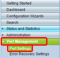
Step 1. Log in to the web-based utility of the switch and choose Port Management > Port Settings.

Step 2. Check the Enable Jumbo Frames check box to support packets up to 9 KB in size. Otherwise, only packets up to 2 KB bytes are supported.

Step 3. Click Apply to save your jumbo frames setting to the running configuration.
Note: Jumbo frames are only enabled when the running configuration is saved to the startup configuration and the device is rebooted.

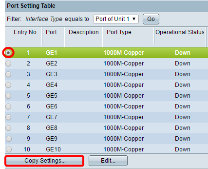
Step 4. To modify the settings of a port, choose its radio button in the Port Setting Table and click Edit.

Note: Depending on the type of port being configured (10G-Copper, 10G-ComboC, etc), some fields described below may not appear or be available.
Step 5. In the Interface area, use the Unit and Port drop-down lists to choose a switch (if the switch is part of a stack) and a port, respectively. This field can be used to quickly navigate to other ports to configure the settings without closing the window. The Port Type area displays the type and speed of the current port.

Step 6. In the Port Description field, enter a description or comment for the current port. This name has no impact on the operation of the switch; it is intended for easier identification.

Step 7. In the Administrative Status area, choose either the Up or Down radio button to determine if the port will be up or down after the switch reboots. The Operational Status area displays whether the port is currently operational or shut down. If the port is down because of an error, it is also displayed here. If the current display mode is Basic, skip to Step 11.

Step 8. Check the Enable Link Status SNMP Traps check box to have the switch generate Simple Network Management Protocol (SNMP) traps that notify of changes to the link status of the port. This feature is not relevant for the OOB (out-of-band) port.

Step 9. Check the Enable Time Range check box to have the port only be up during a preconfigured time range. If not within this time range, the port will be shut down. If there are no time range profiles available, this field is unavailable. This feature is not relevant for the OOB port.

Step 10. Choose a time range profile to apply to the port from the Time Range Name drop-down list. If there are no time range profiles defined, or if you wish to make changes to an existing one, click Edit to go to the Time Range page. The Operational Time-Range State area displays whether the time range is currently active or inactive.

Step 11. Check the Enable Auto Negotiation check box to turn on auto-negotiation for the port. This feature lets a port automatically transmit its transmission speed, duplex mode, and flow control abilities to the port link partner.
If this feature is already enabled, skip to Step 14. The Operational Auto Negotiation area displays the current auto-negotiation status of the port.

Step 12. If auto-negotiation is not enabled, the Administrative Port Speed area becomes available. Choose a radio button to determine the speed of the port; the speeds available vary depending on the type of the port. The Operational Port Speed area displays the current port speed of the port.

Step 13. Depending on the type of port, the Administrative Duplex Mode area may be available. This area can only be configured if auto-negotiation is disabled, and the port speed is 10M (10 Mbps) or 100M (100 Mbps). If the port speed is 1G (1 Gbps), the duplex mode is always full duplex. The Operational Duplex Mode area displays the port’s current duplex mode. Choose a radio button to configure the duplex mode.

The options are:
- Half - The port supports transmission in only one direction at a time.
- Full - The port supports transmission in both directions at the same time.
Step 14. If auto-negotiation is enabled, the Auto Advertisement area will be available. Check the appropriate checkboxes to indicate which capabilities are advertised during auto-negotiation. The Operational Advertisement displays the capabilities currently being advertised by the port. If the current display mode is Basic, skip to Step 17.

The options are:
- Max Capability - All port speeds and duplex mode settings are accepted. This is checked by default. No other check boxes can be chosen if this option is selected.
- 10 Half - 10 Mbps speed and half duplex mode.
- 10 Full - 10 Mbps speed and full duplex mode.
- 100 Half - 100 Mbps speed and half duplex mode.
- 100 Full - 100 Mbps speed and full duplex mode.
- 1000 Full - 1000 Mbps speed and full duplex mode.
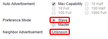
Step 15. In the Preference Mode field, select a radio button to determine whether the port should act as the Active or Slave during auto-negotiation. This field is only available if auto-negotiation is enabled. Configuring the port as the Active, causes it to control and impose its settings on the remote port, and vice-versa. The Neighbor Advertisement displays the advertised capabilities of the remote port.

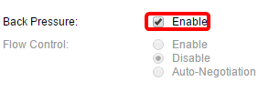
Step 16. (Optional) Check the Enable check box in the Back Pressure area to slow down packet reception speed when the device is congested. This feature is used with half duplex mode, and disables the remote port by preventing it from sending packets and jamming the signal.

Step 17. (Optional) In the Flow Control area, select a radio button to Enable or Disable 802.3x flow control. You can also choose to enable Auto-Negotiation of flow control if the port is in full duplex mode. Flow control is a protocol that the switch can use to halt the transmission of the remote port if the network becomes overwhelmed.

Step 18. In the MDI/MDIX area, choose a radio button to determine the MDI/MDIX (Media Dependent Interface / Media Dependent Interface with Crossover) status of the port. MDI/MDIX refers to which physical pins on the cable the device uses when transmitting and receiving data. The Operational MDI/MDIX area displays the port’s current MDI/MDIX setting.

The options are:
- MDIX - Swap the port’s transmit and receive pairs.
- MDI - Connect this port to a station by using a straight through cable.
- Auto - Configure this device to automatically detect the correct pinouts to use when connecting to another device.
Step 19. (Optional) Check the Enable Protected Port check box to make the port a protected port. A protected port provides layer 2 isolation between interfaces that share the same VLAN.

Note: If the port is a member of a LAG (Link Aggregation Group), its number will appear in the Member in LAG area; otherwise, this field is left blank.

Step 20. Click Apply. The port settings are written to the running configuration file. You can then use the Interface field to navigate to a different port to configure its settings, or click Close to return to the Port Settings page.

Step 21. (Optional) If you want to quickly copy specific port settings to another port, click its radio button, then click Copy Settings.

Step 22. In the to: field, enter the port or range of ports that you want to copy the selected port’s settings to. Then, click Apply.

The screen will then display that the process has been successful. You have now successfully configured port settings on your switch.