Dynamic VLAN Assignment and Auto Smartport Configuration on a SG350X and SG550X
Available Languages
Objective
This document provides instructions on how to configure the Generic VLAN Registration Protocol (GVRP) settings and Auto Smartport on your switches.
If you are unfamiliar with some terms in this document, check out Cisco Business: Glossary of New Terms.
Introduction
Generic Attribute Registration Protocol (GARP) VLAN Registration Protocol or Generic VLAN Registration Protocol (GVRP) allows devices to dynamically exchange Virtual Local Area Network (VLAN) configuration information to make configuration of VLANs easier. When GVRP is globally enabled, the manually/statically created VLANs will automatically propagate the VLAN ID to interconnecting switches and interfaces. Dynamic VLAN Assignment is used to eliminate the chance for error when configuring VLANs when working with large networks. When the switch receives VLAN information through GVRP and GVRP Registration, the receiving interface joins that VLAN. If an interface attempts to join a VLAN that does not exist and Dynamic VLAN creation is enabled, the switch automatically creates the VLAN.
It is important to note that in order for this to work on an access port, the end device has to be GVRP enabled (GVRP enabled NICs if they are servers or PCs).
Smartport is an interface to which a built-in or user-defined macro may be applied. These macros are designed to provide a means of quickly configuring the device to support the communication requirements and utilize the features of various types of network devices. The network access and QoS requirements vary if the interface is connected to an IP phone, a printer, a router, and/or Access Point (AP).
Applicable Devices
- SG350X Series
- SG550X Series
Software Version
- 2.3.5.63
To configure Dynamic VLAN Assignment and Auto Smartport Configuration, follow the guideline below:
Topology:
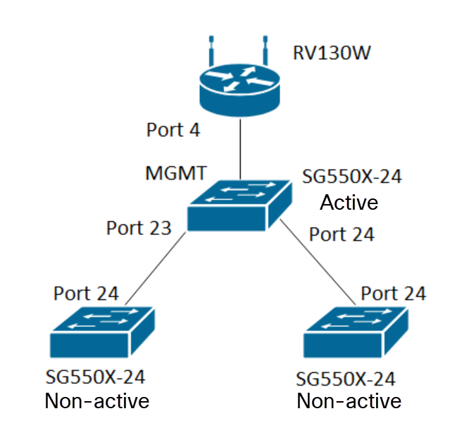
Note: The 2 non-active switches are not connected to the active switch until the conclusion.
The port that is being configured with GVRP must be configured in truck mode or general mode as GVRP requires support for tagging. When the VLAN's propagate from the active switch to the non-active switches via GVRP, it would be considered as dynamic VLANs.
Note: If there is an error "vlan not created by user", then only static VLANs (manually created) can be added to a port configured as an access port. GVRP does not work the same as VTP (Server – Client).
The steps below are configured in Advanced mode in the Display Mode field at the top of the web configuration page.

Table of Contents
- Configuring Auto Smartports on the SG350XG and SG550XG
- Configure GVRP settings on the SG550X-24 (active)
- Setting up VLAN settings on the SG550X-24 (active)
- How to Configure Interface settings on SG550X-24 (active)
- How to Set Up Port VLAN Membership on the active Switch
- Configuring GVRP on the Non-active switch
- Setting up Interface settings on the Non-active switch
- Verification
Configure GVRP Settings on the SG550X-24 (active)
To learn more about configuring GVRP Settings on a switch, click here.
Step 1. Log in to the web-based utility of your active switch and navigate to VLAN Management > GVRP Settings.
Note: In this example, one of the SG550X-24 will be the active switch.
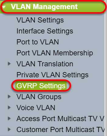
Step 2. Check the Enable checkbox to enable GVRP Global Status to globally enable GVRP on the switch.

Step 3. Click Apply to enable GVRP features.

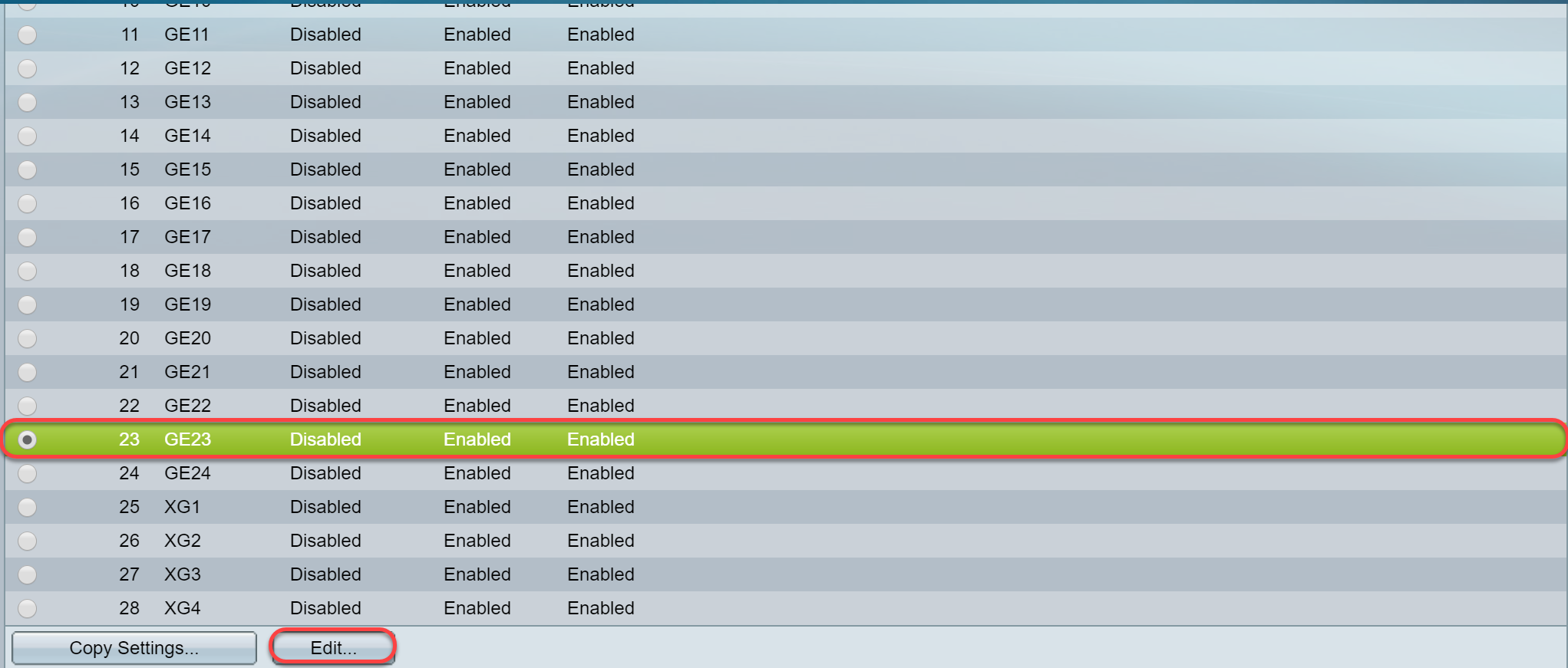
Step 4. Click the radio button of the interface on which you would like to configure GVRP. Then click Edit... to modify the GVRP settings for the selected interface.
Note: In this example, we will be configuring GE23 and GE24.
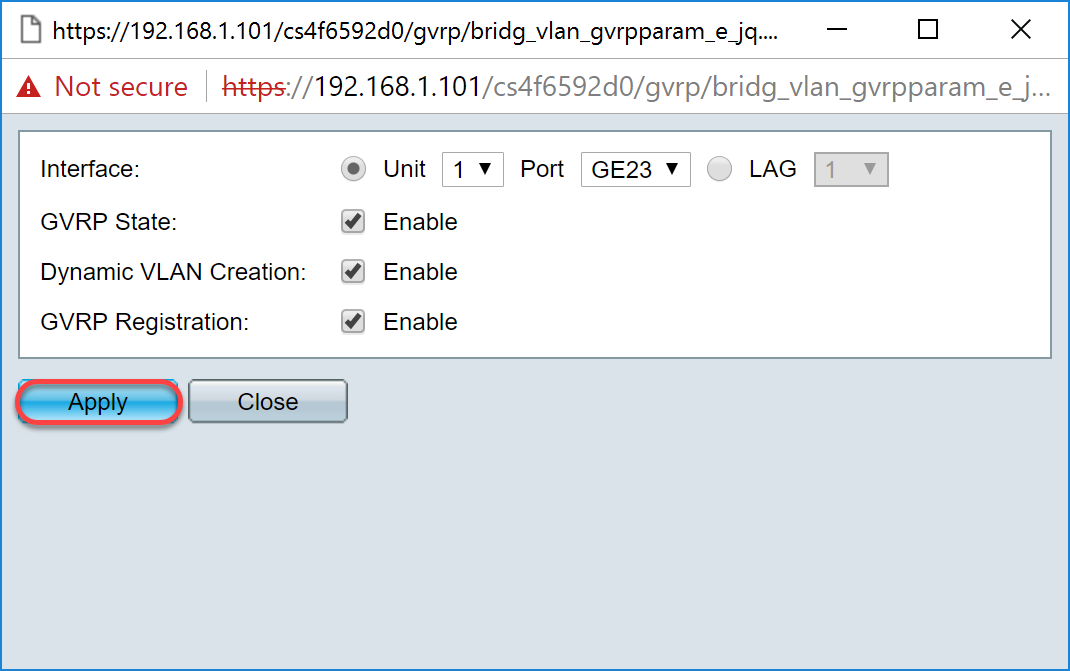
Step 5. The Edit GVRP Setting window appears.
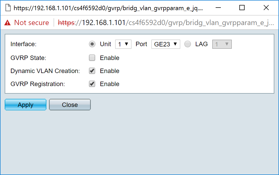
Step 6. (Optional) Click the appropriate radio button and choose a new interface from the Port or Link Aggregation Group (LAG) drop-down list to change the interface whose settings you want to change. LAG bundles individual Ethernet links into a single logical link that can increase the throughput further than a single connection can support.
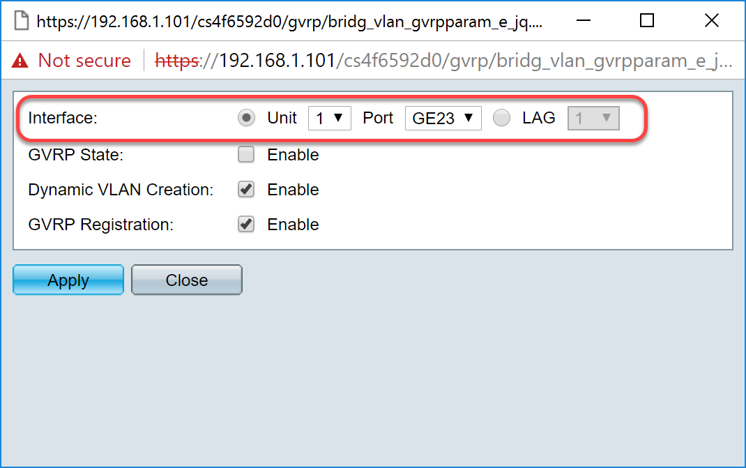
Step 7. Check the Enable checkbox in the GVRP State field to enable GVRP features on this interface.
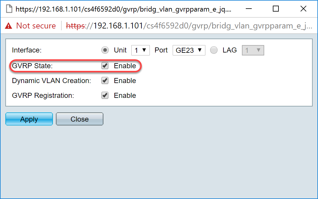
Step 8. Check the Enable check box in the Dynamic VLAN Creation field to have a VLAN dynamically created if it does not exist when GVRP information is received for that VLAN on the selected interface. If Dynamic VLAN Creation is disabled, the switch only recognizes VLANs that have been manually created.
Note: This is enabled by default.
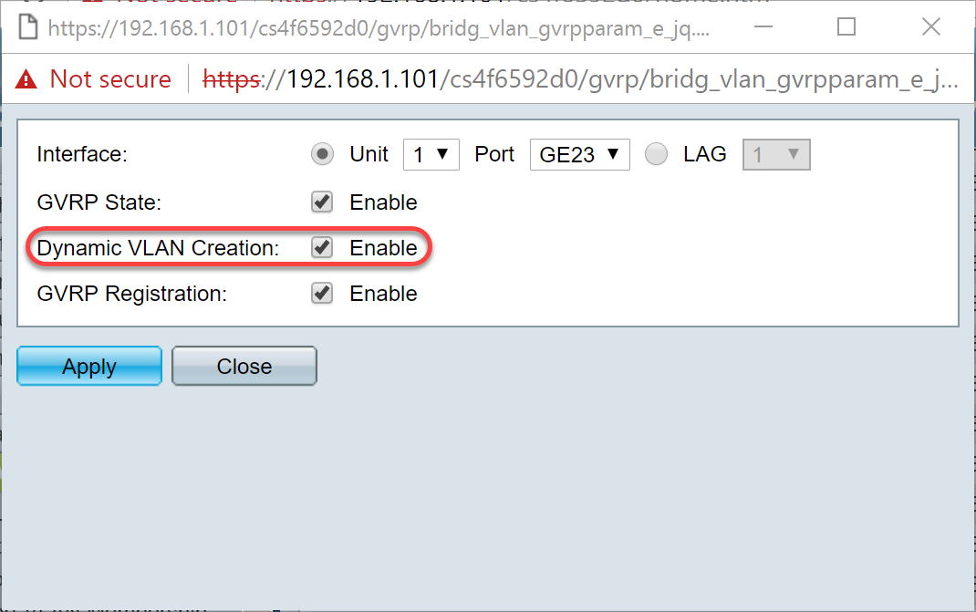
Step 9. (Optional) Check the Enable check box in the GVRP Registration field to have the selected interface join a VLAN when GVRP information is received for that VLAN on the selected interface. If GVRP registration is disabled, an interface only associates with a VLAN that it is manually configured to be on.
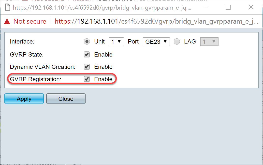
Step 10. Click Apply to save the updated GVRP settings for the selected interface and then click Close to exit the Edit GVRP Setting window.
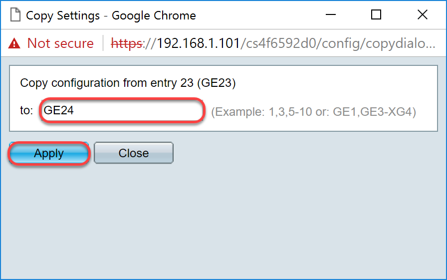
Step 11. (Optional) To copy the GVRP settings of one interface to several other interfaces, click the radio button of the desired interface and click Copy Settings. The Copy Settings window appears.

Step 12. (Optional) Enter the interface number(s) or interface name(s) of the interface(s) to which you wish to copy the settings of the chosen interface in the provided field. Then click Apply to save your changes or click Close to cancel your changes.
Setting Up VLAN Settings on the SG550X-24 (active)
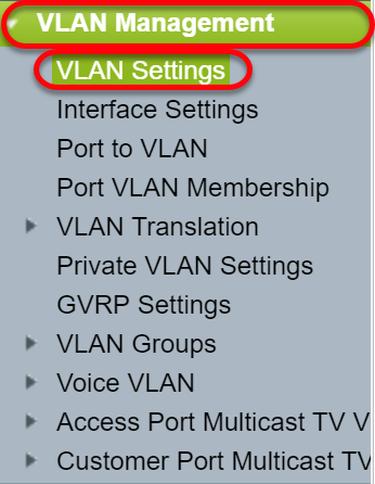
Step 1. Navigate to VLAN Management > VLAN Settings.
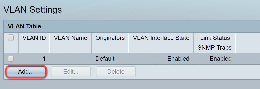
Step 2. Click Add... to create new VLANs. The Add VLAN window appears.
Note: There are two ways to create a VLAN. You can create a single VLAN or you can set a range of new VLANs. In this example, we will be creating a range of VLANs.
Step 3. To create a single VLAN, click the VLAN radio button. Then enter the following information:
- VLAN ID — The ID of the new VLAN.
- VLAN Name — The name of the new VLAN
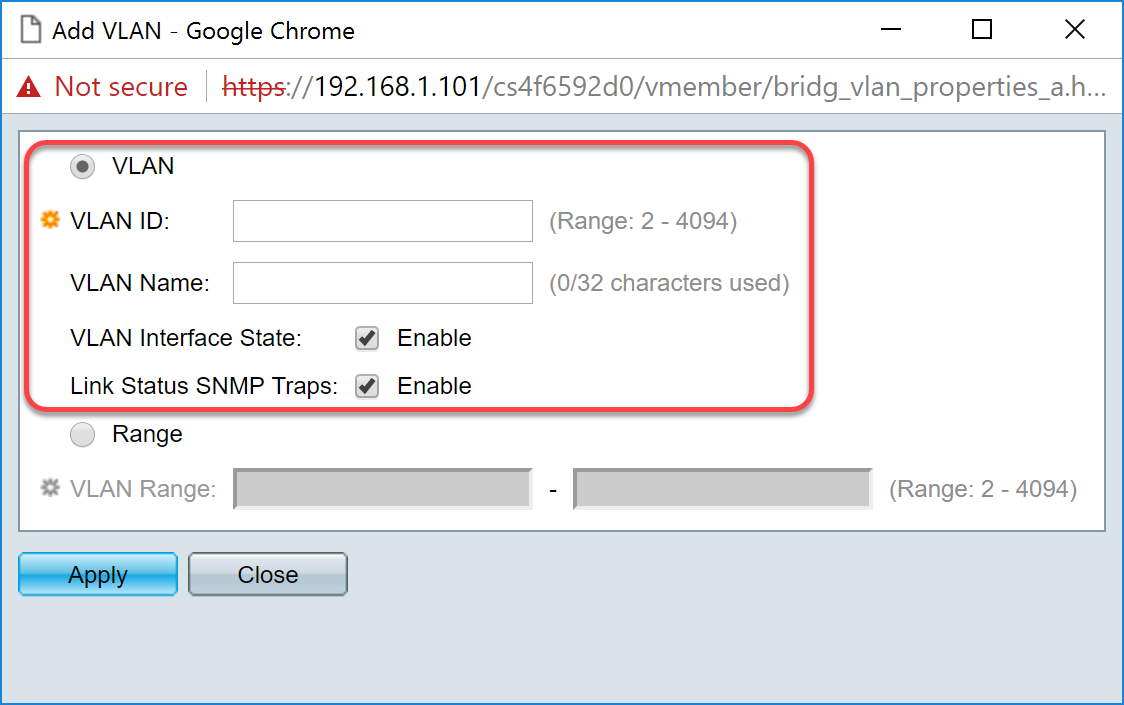
Step 4. To create a range of VLANs, click the Range radio button. Then enter the following information:
- VLAN Range — The range, according to the number of VLANs you want to create. For example, if you want to create 10 VLANs, then enter a range that will fit your needs. In this example, we will create VLAN 10 to 20.
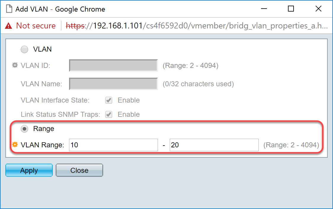
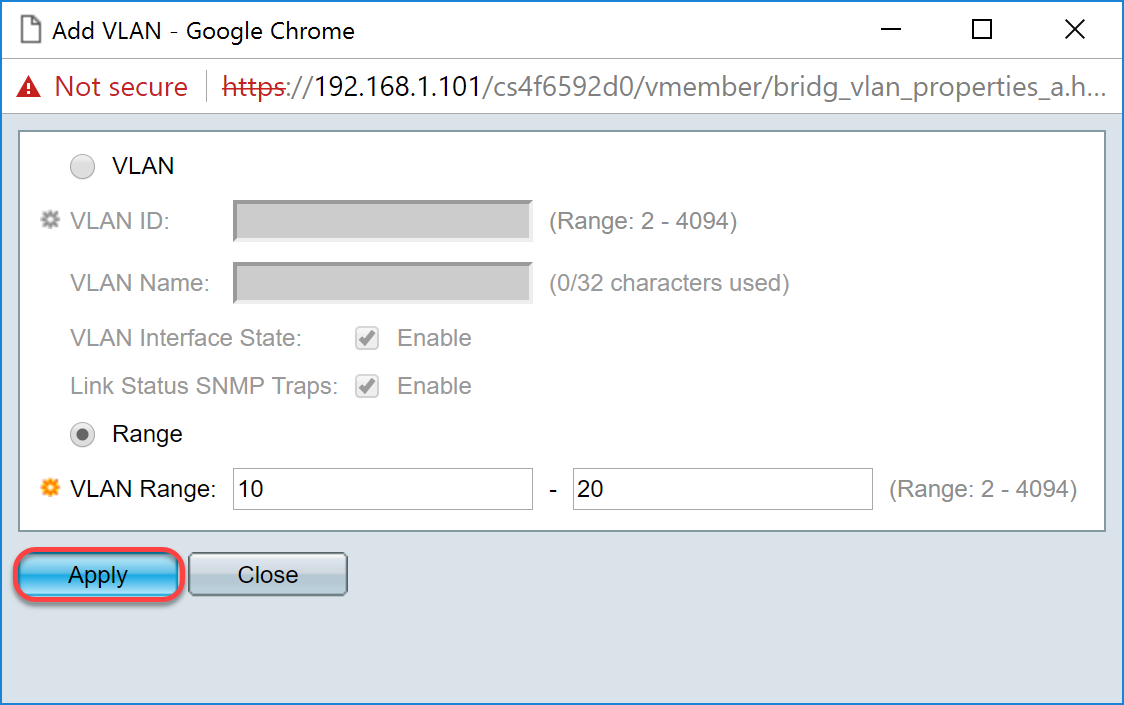
Step 5. Click Apply to save your configuration.
How to Configure Interface Settings on the SG550X-24 (active)
Step 1. Navigate to VLAN Management > Interface Settings.
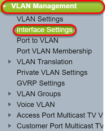
Step 2. Select a Global Ethertype Tagging method. The options are:
- Dot1q-8100 — Also known as IEEE 802.1Q. It is the standard for tagging frames on a trunk and supports up to 4096 VLANs. The TPID is usually set to 0x8100 to identify the frame as an IEEE802.1Q frame.
- Dot1ad-88a8 — implements a standard protocol for double tagging of data by using a feature called QinQ. Data traffic coming from the customer side are double tagged in the provider network where the inner tag is the customer-tag (C-tag) and the outer tag is provider-tag (S-tag). S-VLAN tag or S-tag is known as Service tag which is used to forward packets into the provider network. The S-tag segregate traffic between various customers, while preservice the customer VLAN tags. This is done with QinQ which provides isolation between service provider networks and customers' networks. The device is a provider bridge that supports port-based c-tagged service interface.
- 9100 — Non-standard QinQ ethertype
- 9200 — Non-standard tagging.
Note: In this example, we used the default Dot1q-8100 for the Global Ethertype Tagging.

Step 3. Click Apply.
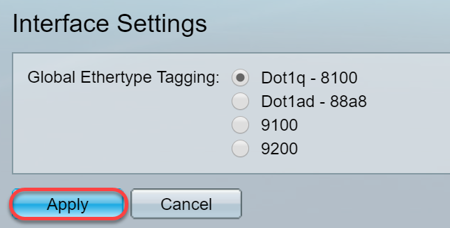
Step 4. Click the radio button of the interface that you have configured GVRP. Ports that are configured with GVRP needs to be configured as trunk ports.
Note: In this example, we will be configuring GE23 and GE24 as trunk ports.

Step 5. Click Edit... to edit the interface. The Edit Interface Settings windows opens.
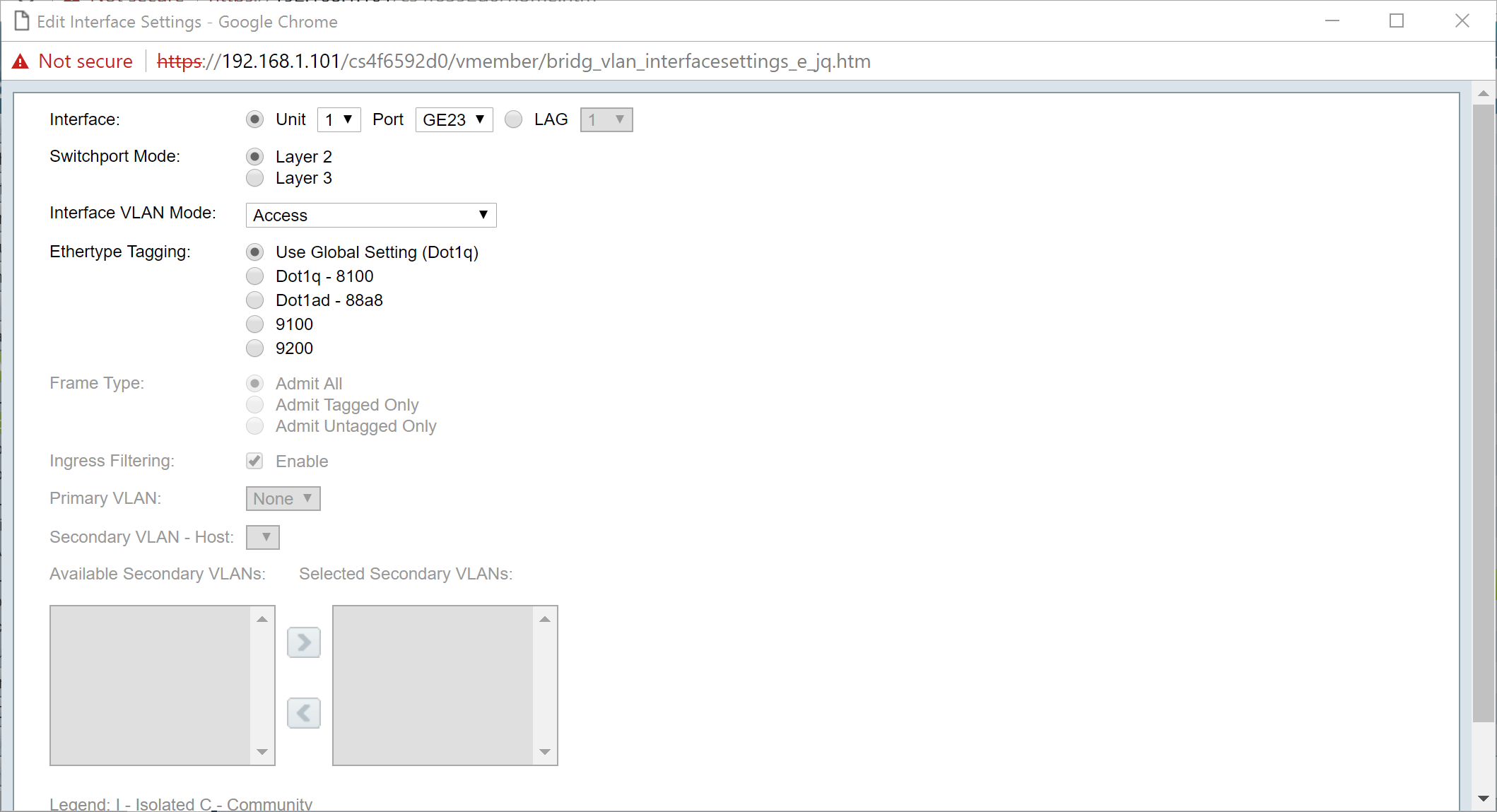
Step 6. (Optional) Click the appropriate radio button and choose a new interface from the Port or LAG drop-down list to change the interface whose settings you want to change.
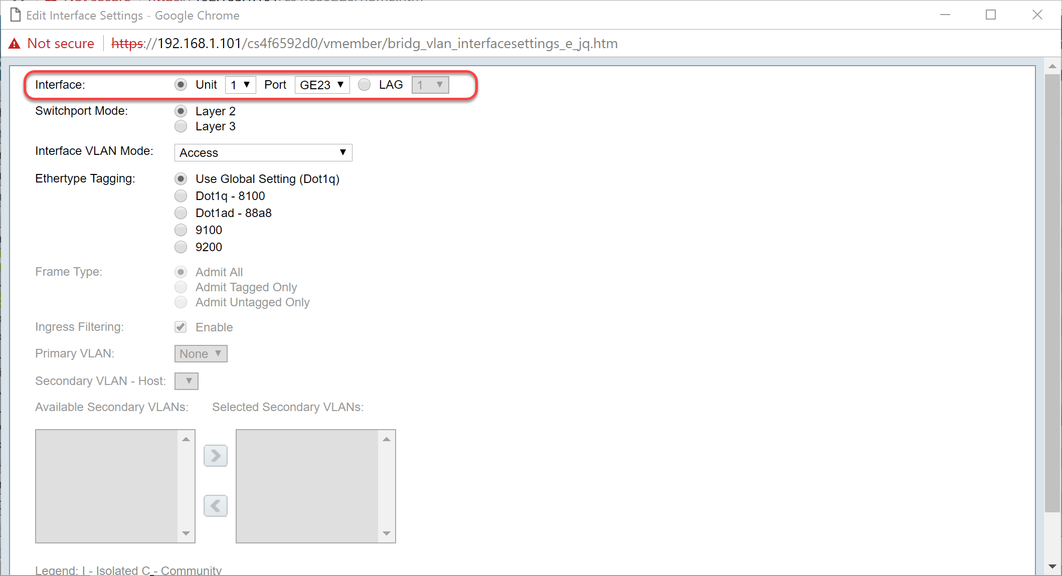
Step 7. Select either Layer 2 or Layer 3 in the Switchport Mode field.
Note: In this example, the default (Layer 2) was selected.
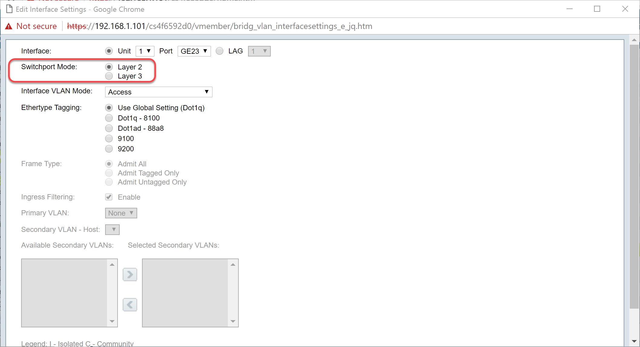
Step 8. Select Trunk in the Interface VLAN Mode drop-down list. The interface is an untagged member of one VLAN at most, and is a tagged member of zero or more VLANs.
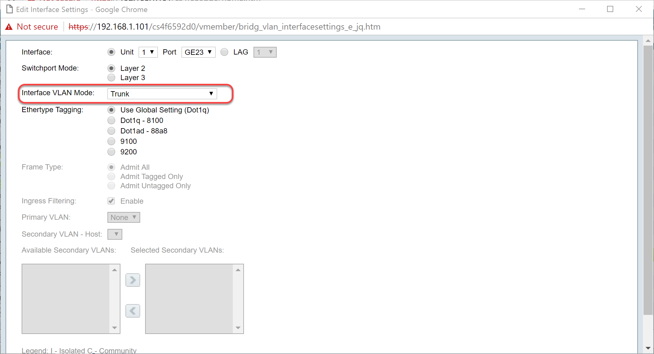
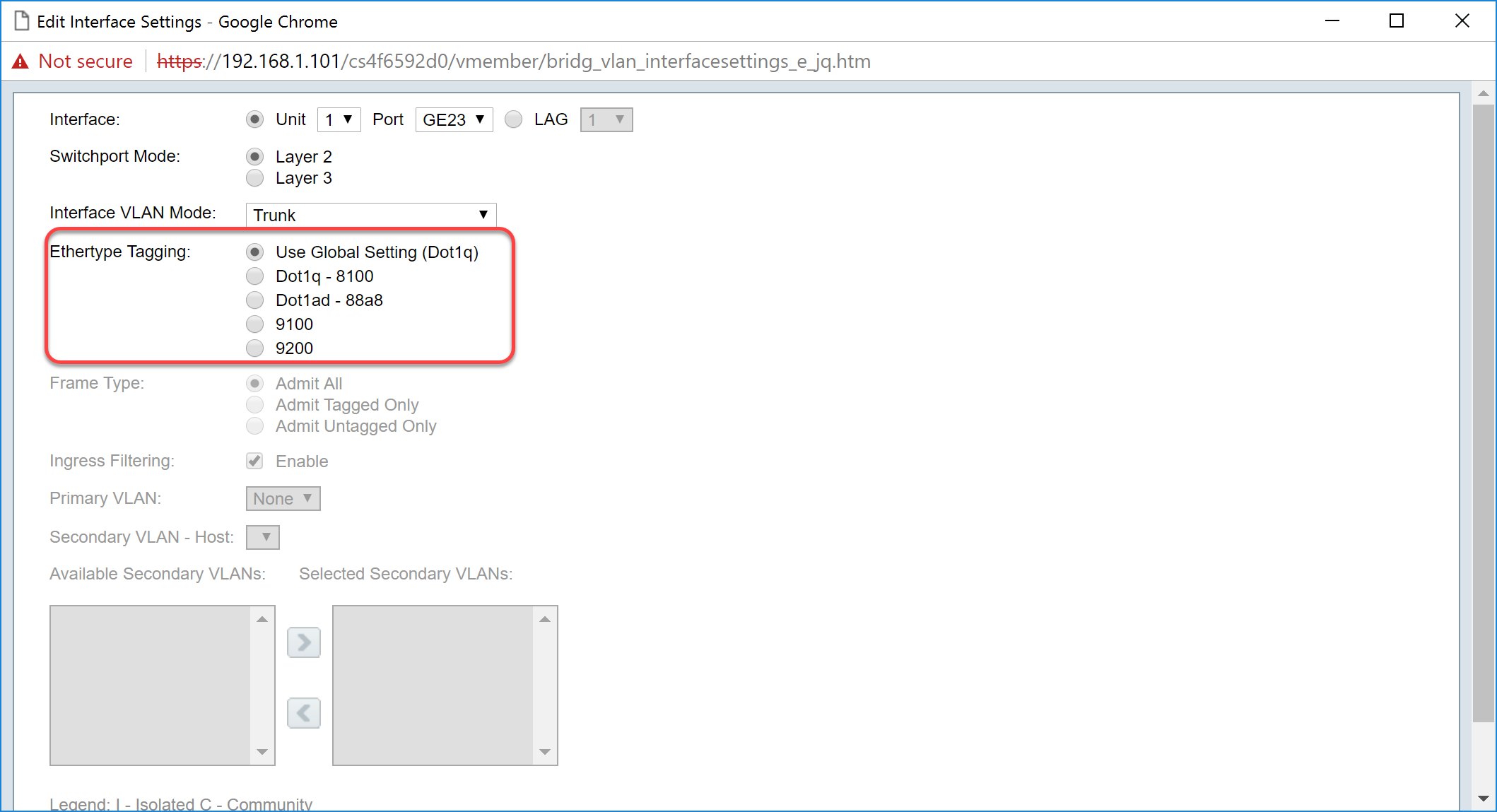
Step 9. Select an Ethertype Tagging method for the S-VLAN tag. The options are:
- Use Global Setting (Dot1q)
- Dot1q - 8100
- Dot1ad - 88a8
- 9100
- 9200
Note: In this example, we used the default value: Use Global Setting (Dot1q).
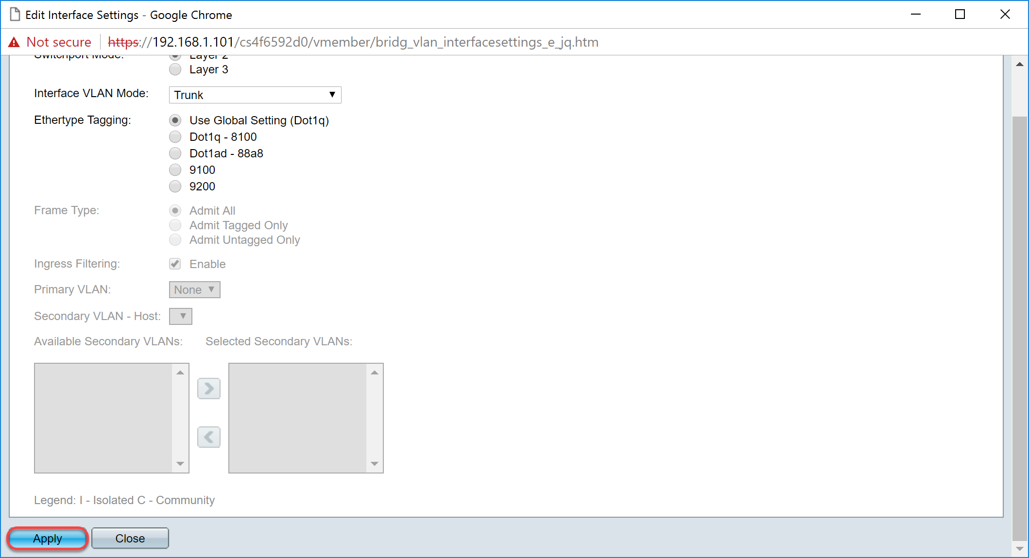
Step 10. Then click Apply to save the changes.
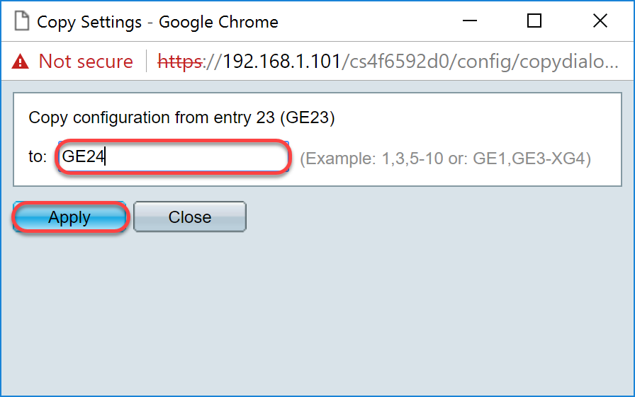
Step 11. (Optional) If you have configured GVRP on more than one interface then you can select the interface that you have just configured and click Copy Settings.... This will allow you to copy the configuration that you have just configured to other interfaces.

Step 12. (Optional) In the pop-up window that appears, enter the port where you wish to apply the same settings and click Apply.
Note: In this example, the settings from GE23 are going to be copied to GE24 only.
How to Set Up Port VLAN Membership Settings on the active Switch
Step 1. Navigate to VLAN Management > Port VLAN Membership.
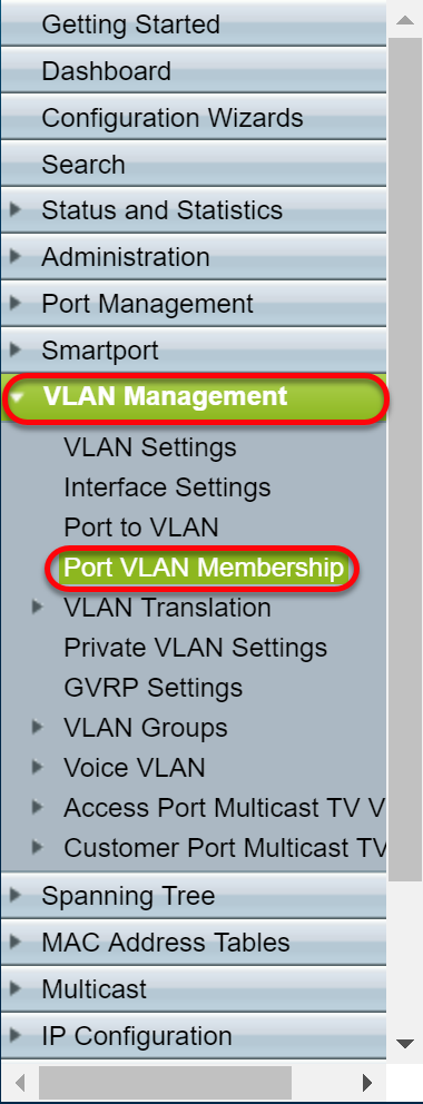
Step 2. Click the radio button of the interfaces that you have configured as trunk port.Then click Join VLAN... to edit the VLAN membership of that interface.

Step 3. (Optional) Click the appropriate radio button and choose a new interface from the Port or LAG drop-down list to change the interface whose settings you want to change.
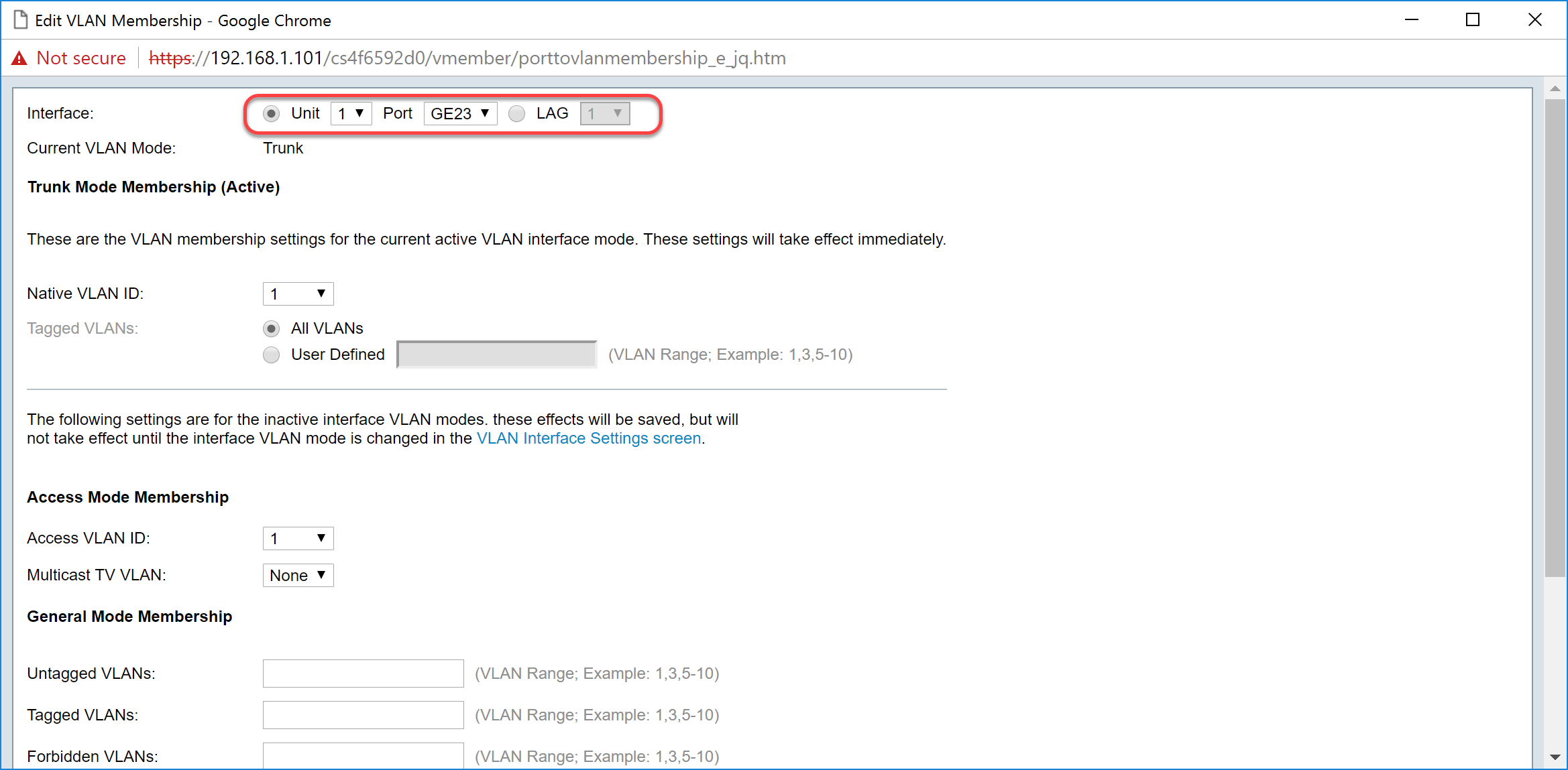
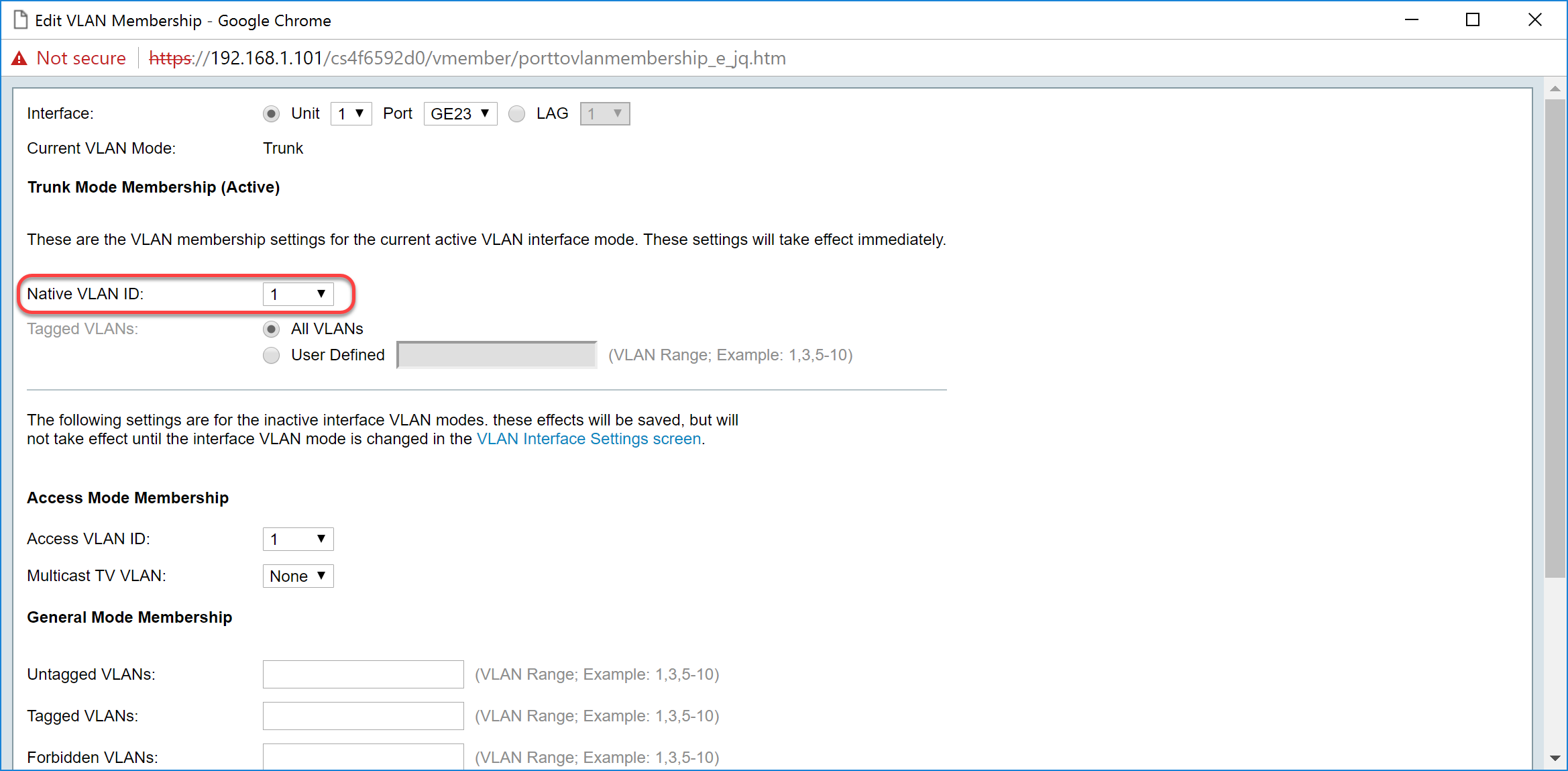
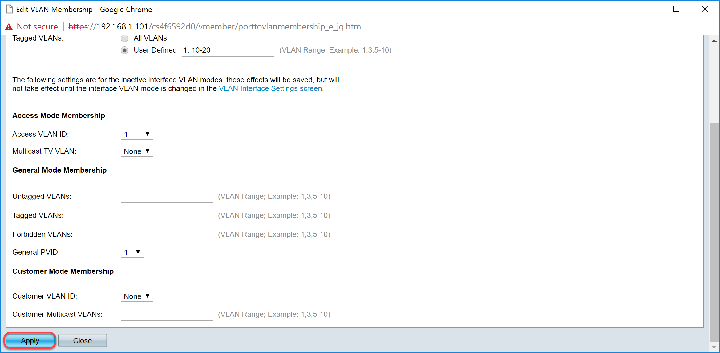
Step 4. When the port is in Trunk mode, it will be a member of this VLAN. Select the Native VLAN ID in the Native VLAN ID drop-down list.
Note: In this example, we will be using VLAN 1 as the native VLAN ID.
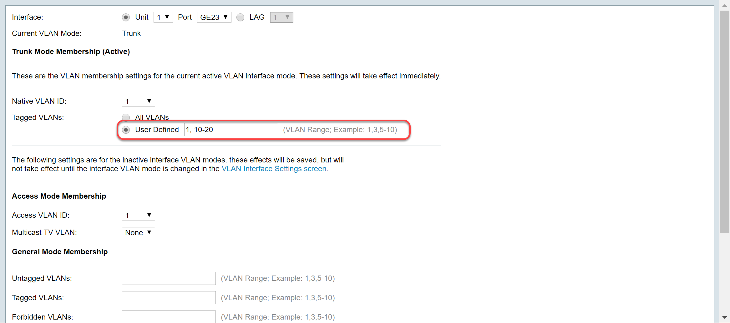
Step 5. Select User Defined radio button in the Tagged VLANs field. Then enter the VLAN ID's that you want this port to be a member of.
Note: In this example, we will be using VLAN: 1, 10-20 for GE23 and GE24.
Step 6. Then click Apply to save your changes.
Note: Repeat steps 2-6 if you have more interfaces that needs to be configured.
Step 7. Press the Save button on the top to save your configuration to the startup configuration file.

Configuring GVRP Settings on the Non-active Switch
Step 1. Log into the web configuration page of the non-active switch and navigate to VLAN Management > GVRP Settings. The GVRP Settings page opens.
Note: Since the non-active switches is not connected to the active switch, the default IP address is 192.168.1.254. You would have to put your PC to have a static IP address in that network in order to connect to it.
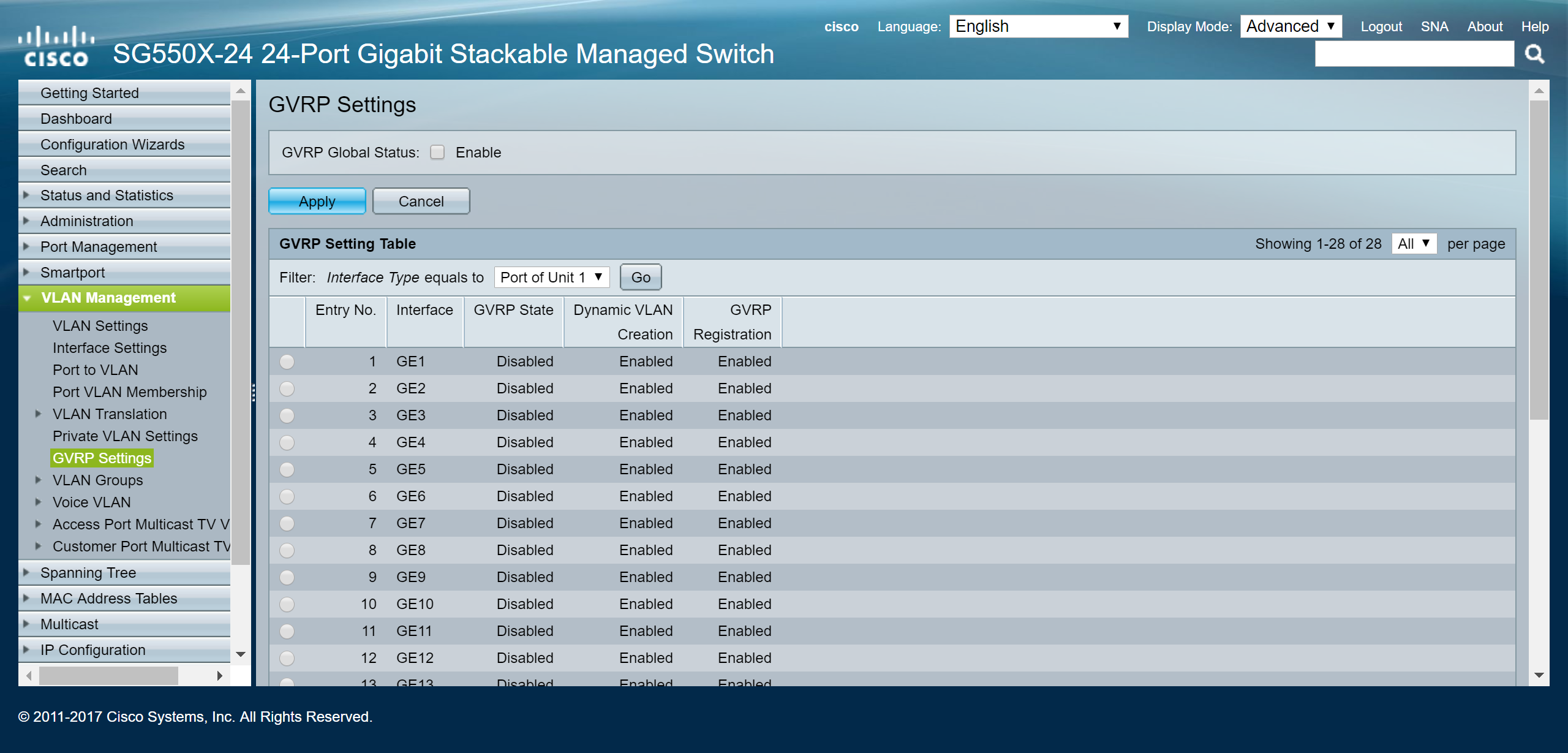
Proceed to configure the same way as the section: Configure GVRP Settings on SG550X-24 (active) for both of the non-switches. Configure only the port that is going to be connected to the active SG550X-24 switch. In this example, both of the non-active switch is using port 24 to connect to the active switch.
Setting Up Interface Settings on SG550X-24 Non-active Switch
Step 1. Navigate to VLAN Management > Interface Settings. The Interface Settings page opens.
Note: Since the non-active switches is not connected to the active switch, the default IP address is 192.168.1.254. You would have to put your PC to have a static IP address in that network in order to connect to it.
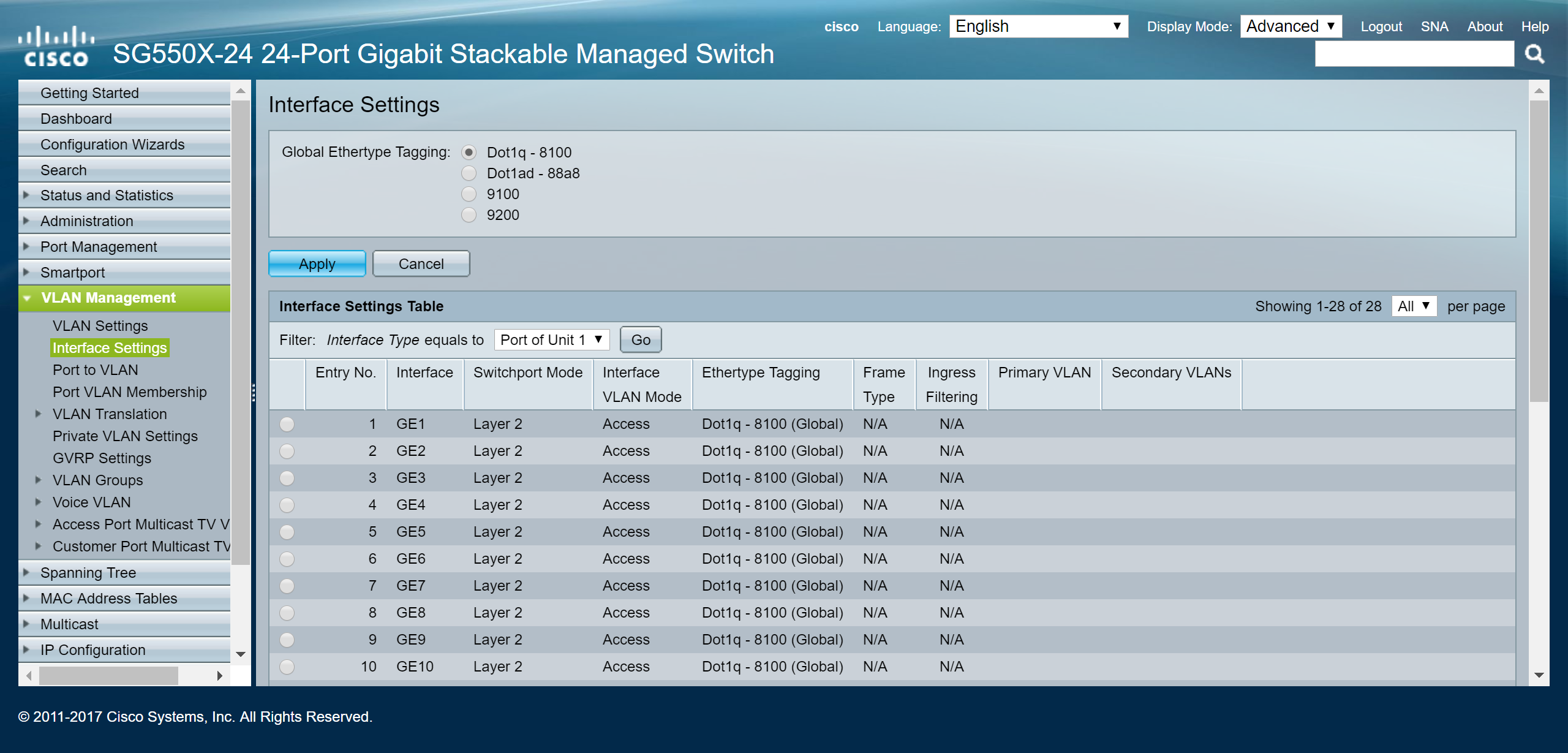
Proceed to configure the same way as: How to Configure Interface Settings on the SG550X-24 (active) for both of the non-switches. Configure only the port that is connected to the active switch as trunk port. In this example, GE24 is configured as trunk for both of the switches.
Verification
Before we can verify that GVRP is working, there is a few more steps that needs to be done. Follow the last few steps below:
Step 1. Connect the cable from your non-active switch to the active switch.
Note: In this example, we will be connecting one of the non-active SG550X-24 (port 24) to the active SG550X-24 (port 23).
Step 2. Connect the cable from your second non-active switch to the active switch.
Note: In this example, we will be connecting the other non-active SG550X-24(port 24) to the active SG550X-24 (port 24).
Note: If you don't see any VLANs created by GVRP automatically in the VLAN Management > Create VLAN. A reboot may be required for your switches.
Step 3. Navigate to VLAN Management > Create VLAN on the non-active switch to see if VLAN 10-20 has been created.
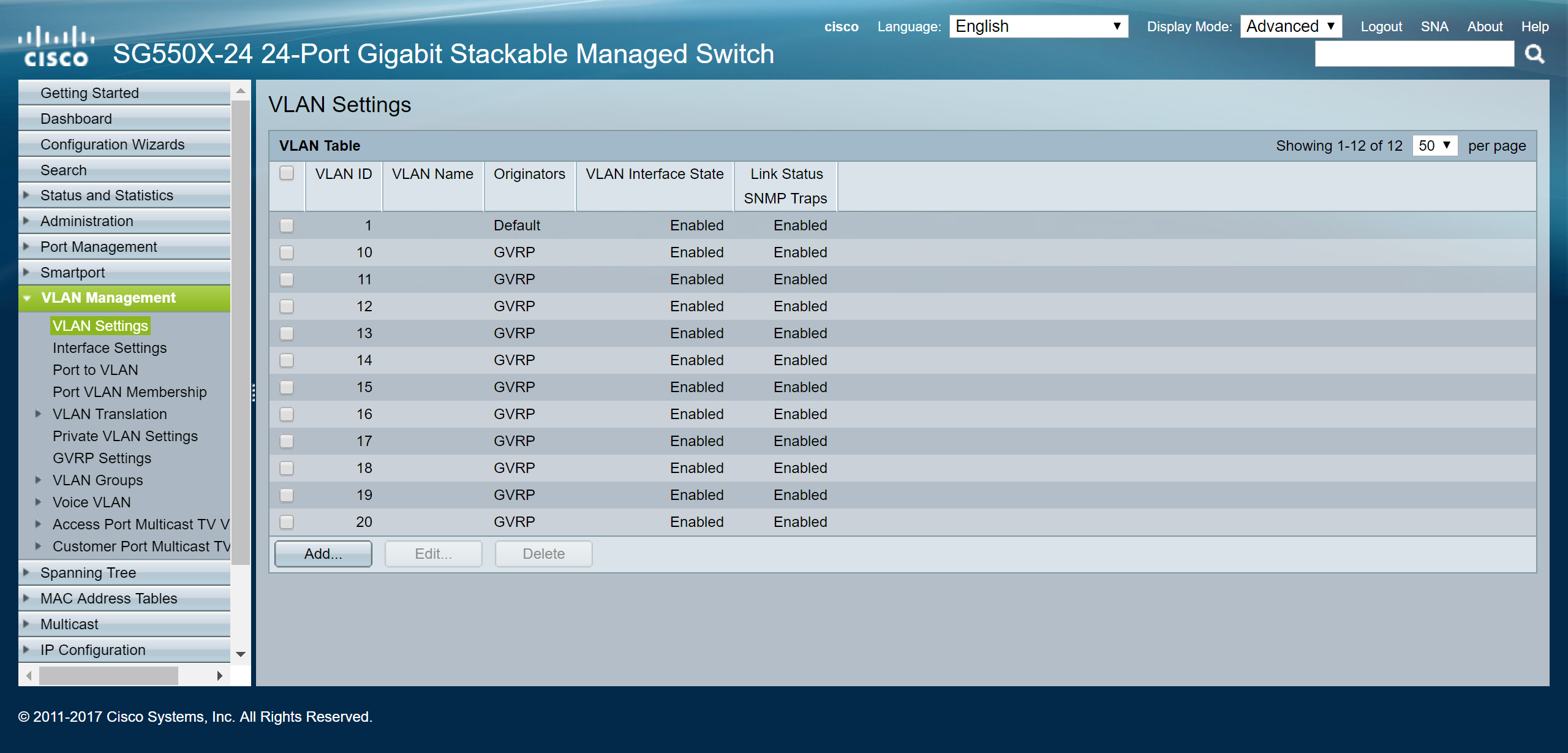
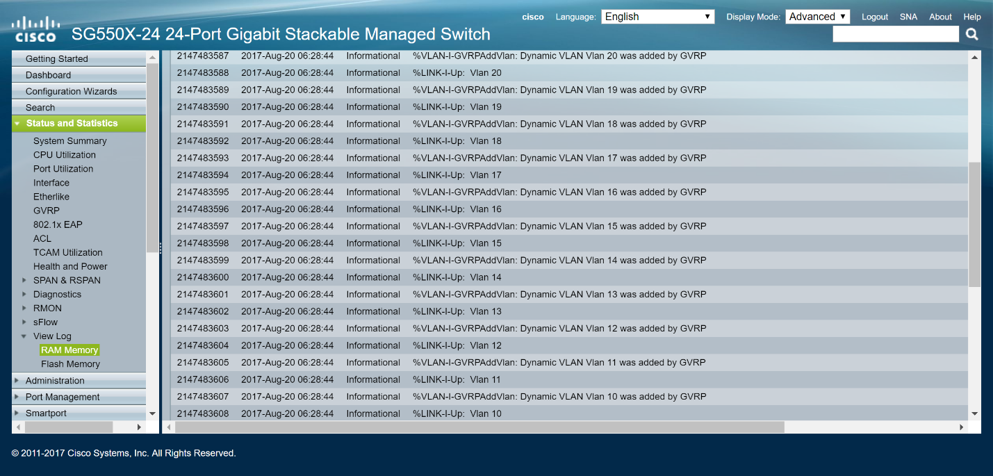
Step 4. Navigate to Status and Statistics > View Log > RAM Memory and check to see if GVRP has created VLAN 10-20 for both of the non-active switches.
Conclusion
You have now successfully configured Dynamic VLANs and Auto Smartport configuration.
Check out the following links to view related videos:
Configuring Generic VLAN Registration Protocol (GVRP) on Cisco RV345
 Feedback