Aironet接入點上的VLAN配置示例
目錄
簡介
本文提供一個組態範例,顯示如何使用指令行介面(CLI)在Cisco Aironet存取點(AP)上設定VLAN。
必要條件
需求
嘗試此組態之前,請確保符合以下要求:
-
瞭解Aironet AP的基本配置
-
瞭解使用Aironet案頭實用程式配置Aironet 802.11a/b/g客戶端介面卡
-
Cisco Catalyst交換機和思科路由器配置的基本知識
採用元件
本文中的資訊係根據以下軟體和硬體版本:
-
執行Cisco IOS®軟體版本12.4(3g)JA1的Aironet 1240AG系列AP
-
Aironet 802.11a/b/g使用者端配接器
-
運行韌體版本2.5的Aironet案頭實用程式
-
執行Cisco IOS軟體版本12.1(19)EA1的Catalyst 2950交換器
-
執行Cisco IOS軟體版本12.4(11)T的2800 ISR路由器
本文中的資訊是根據特定實驗室環境內的裝置所建立。文中使用到的所有裝置皆從已清除(預設)的組態來啟動。如果您的網路正在作用,請確保您已瞭解任何指令可能造成的影響。
慣例
網路圖表
本檔案會使用此網路設定。
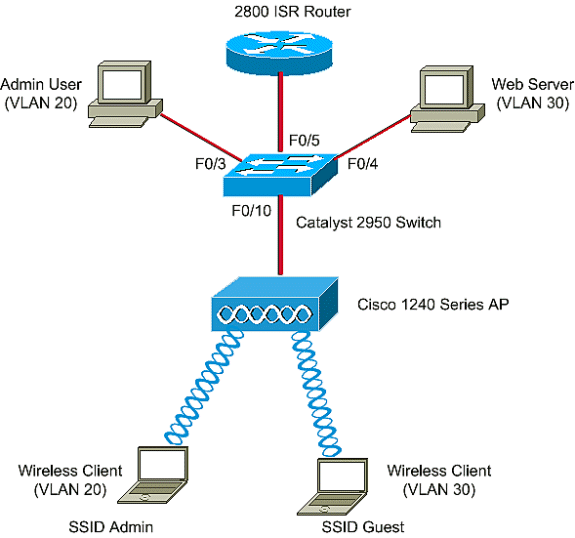
Aironet 1200系列AP有三個VLAN - VLAN 2、VLAN 20和VLAN 30。本文檔中的設定使用VLAN 2作為本徵VLAN,使用VLAN 20作為管理(管理)部門,使用VLAN 30作為訪客使用者。屬於管理部門的無線使用者必須連線到AP,並且應該能夠連線到有線網路(VLAN 20上)上的管理部門的使用者。 無線訪客使用者必須能夠連線到VLAN 30上有線網段上的Web伺服器。Catalyst 2950交換機將AP連線到有線網路。2800 ISR路由器連線到同一台交換機,充當屬於VLAN 20和VLAN 30的無線客戶端的DHCP伺服器。路由器需要將IP地址分配給來自其各自子網的客戶端。必須配置AP、Catalyst交換機和路由器才能實施此設定。

以下是檔案中用於裝置的IP地址清單。所有IP地址都使用/24子網掩碼
-
AP網橋組虛擬介面(BVI)IP地址(VLAN 2)- 172.16.1.20
-
連線到VLAN 20的無線客戶端(SSID管理員)從子網172.16.2.0的路由器的DHCP伺服器獲取IP地址
-
連線到VLAN 30的無線客戶端(SSID訪客)從子網172.16.3.0的路由器的DHCP伺服器獲取IP地址
-
VLAN 20上有線網路上的管理員使用者 — 172.16.2.60(靜態IP)
-
VLAN 30上的Web伺服器 — 172.16.3.60(靜態IP)
-
VLAN 2中路由器的子介面 — 172.16.1.1
-
VLAN 20中路由器的子介面 — 172.16.2.1
-
VLAN 30中路由器的子介面 — 172.16.3.1
設定
本節提供用於設定本文件中所述功能的資訊。
註:使用Command Lookup Tool(僅限註冊客戶)查詢有關本文檔中使用的命令的更多資訊。
為了配置AP以連線到特定VLAN,您必須配置服務集識別符號(SSID)以識別VLAN。VLAN ID或名稱用於標識VLAN。因此,如果您在AP上配置SSID以識別特定VLAN ID或名稱,則可以建立與VLAN的連線。建立連線後,使用特定SSID連線到AP的無線客戶端將分配給該VLAN。由於您最多可在AP上配置16個SSID,因此您可以在AP上建立16個VLAN。要在AP上配置VLAN並建立連線,您必須完成以下步驟:
在AP上配置本徵VLAN
接入點本身和接入點所連線的其他基礎設施裝置(如交換機)所連線的VLAN稱為本地VLAN。接入點的本徵VLAN通常與接入點上配置的其他VLAN不同。它是BVI interface,用於管理在本徵VLAN子網中分配了IP地址的接入點。傳送到接入點本身並由接入點本身傳送的流量(例如,管理流量)採用本徵VLAN,且未標籤。在IEEE 802.1Q(dot1q)中繼埠上接收的所有未標籤流量都使用為該埠配置的本地VLAN進行轉發。如果封包的VLAN ID與傳送連線埠的本徵VLAN ID相同,則交換器會傳送封包而不使用標籤。否則,交換器會傳送包含標籤的封包。
要在AP上配置本徵VLAN,請在AP的全域性配置模式下發出以下命令:
AccessPoint<config>#interface fastethernet 0.2
AccessPoint<config-subif>#encapsulation dot1q 2 native

!--- Configure the encapsulation as dot1q and assign VLAN 2 as the native VLAN !--- on the Fast Ethernet interface.

AccessPoint<config-subif>#exit
AccessPoint<config>#interface dot11radio 0.2
AccessPoint<config-subif>#encapsulation dot1q 2 native

!--- Configure the encapsulation as dot1q and assign VLAN 2 as the native VLAN !--- on the radio interface.

AccessPoint<config-subif>#end
為AP上的訪客使用者和管理員使用者配置VLAN
在這裡,您需要配置兩個VLAN,一個用於訪客使用者,另一個用於管理部門使用者。您還需要將SSID與特定VLAN相關聯。此示例配置:
-
VLAN 20用於管理部門,並使用SSID Admin
-
VLAN 30用於訪客使用者並使用SSID Guest
若要設定這些VLAN,請在全域組態模式下輸入以下命令:
AccessPoint#configure terminal

!--- Enter global configuration mode.

AccessPoint(config)#interface dot11radio 0

!--- Enter radio interface configuration mode.

AccessPoint(config-if)#ssid Admin

!--- Configure the SSID "Admin".

AccessPoint(config-if-ssid)#vlan 20

!--- Assign VLAN 20 to the SSID.

AccessPoint(config-if-ssid)#authentication open

!--- Configure open authentication for the SSID.

AccessPoint(config-if-ssid)#end
AccessPoint(config) interface fastethernet 0.20

!--- Enter subinterface mode on the Fast Ethernet interface.

AccessPoint(config-subif) encapsulation dot1Q 20

!--- Set the encapsulation as dot1q for VLAN 20.

AccessPoint(config-subif) bridge-group 20

!--- Assign the subinterface to bridge group 20.

AccessPoint(config-subif) exit
AccessPoint(config) interface dot11radio 0.20

!--- Enter subinterface mode on the radio interface.

AccessPoint(config-subif) encapsulation dot1Q 20

!--- Set the encapsulation as dot1q for VLAN 20.

AccessPoint(config-subif) bridge-group 20

!--- Assign the subinterface to bridge group 20.

AccessPoint(config-subif) exit
重複相同步驟,為管理員使用者設定VLAN 30:
AccessPoint#configure terminal
AccessPoint(config)#interface dot11radio 0
AccessPoint(config-if)#ssid Guest
AccessPoint(config-if-ssid)#vlan 30
AccessPoint(config-if-ssid)#authentication open
AccessPoint(config-if-ssid)#end
AccessPoint(config) interface fastethernet 0.30
AccessPoint(config-subif) encapsulation dot1Q 30
AccessPoint(config-subif) bridge-group 30
AccessPoint(config-subif) exit
AccessPoint(config) interface dot11radio 0.30
AccessPoint(config-subif) encapsulation dot1Q 30
AccessPoint(config-subif) bridge-group 30
AccessPoint(config-subif) exit
注意:本文檔對SSID管理員和訪客使用開放式身份驗證。身份驗證型別與為AP配置的SSID關聯。有關如何在AP上配置不同身份驗證型別的資訊,請參閱配置身份驗證型別。
設定Catalyst交換器
下一步是配置交換機埠,以便將AP和路由器連線到有線網路。您應將連線到AP和路由器的交換機埠配置為中繼埠,因為該埠傳輸來自無線網路上所有VLAN的流量。在本例中,VLAN是VLAN 20、VLAN 30和本徵VLAN 2。配置連線到AP和路由器的交換機埠時,請確保配置的本徵VLAN與AP和路由器上的本徵VLAN匹配。否則,幀會被丟棄。若要設定交換器上的主干連線埠,請從交換器上的CLI發出以下命令:
註:本檔案使用Catalyst 2950交換器。交換器連線埠上的組態會有所不同,這取決於您使用的交換器型號。如圖所示,介面fastethernet 0/5連線到路由器,介面fastethernet 0/10連線到接入點。
Switch#configure terminal
Switch<config>#interface fastethernet 0/5

!--- Enter the interface mode for Fast Ethernet 0/5.

Switch<config-if>#switchport mode trunk

!--- Configure the switch port mode to trunk mode.

Switch<config-if>#switchport trunk encapsulation dot1q

!--- Configure the encapsulation on the switch port to dot1q.

Switch<config-if>#switchport trunk native vlan 2

!--- Configure the native VLAN as VLAN 2.

Switch<config-if>#switchport trunk allowed vlan add 2,20,30

!--- Configure the list of VLANs that are allowed on the trunk port.

Switch<config-if>#switchport nonegotiate


Switch#configure terminal
Switch<config>#interface fastethernet 0/10

!--- Enter the interface mode for Fast Ethernet 0/10

Switch<config-if>#switchport mode trunk

!--- Configure the switch port mode to trunk mode.

Switch<config-if>#switchport trunk encapsulation dot1q

!--- Configure the encapsulation on the switch port to dot1q.

Switch<config-if>#switchport trunk native vlan 2

!--- Configure the native VLAN as VLAN 2.

Switch<config-if>#switchport trunk allowed vlan add 2,20,30

!--- Configure the list of VLANs that are allowed on the trunk port.

Switch<config-if>#switchport nonegotiate
注意:基於Cisco IOS軟體的Aironet無線裝置不支援動態中繼協定(DTP)。 因此,交換機不得嘗試協商DTP。
配置路由器
路由器配置為VLAN 20和VLAN 30中無線客戶端的DHCP伺服器。該路由器有三個子介面,每個VLAN 2、20和30各一個,以便它可以為各自的VLAN子網中的客戶端分配IP地址並執行VLAN間路由。
Router#configure terminal
Router<config>#interface fastethernet 0/0.2

!--- Configures a Sub-interface .2 on fastethernet 0/0

Router<config-subif>#encapsulation dot1q 2 native

!--- configures the encapsulation as dot1q and assigns VLAN 2 to the sub-interface This command also makes VLAN 2 as the Native VLAN. Here number 2 is the VLAN-id.

Router<config-subif>#ip address 172.16.1.1 255.255.255.0

!--- Assign ip address from Native VLAN 2 subnet - 172.16.1.0 /24 to the sub-interface

Router<config-subif>#exit
Router<config>#interface fastethernet 0/0.20

!--- Configures a Sub-interface .20 on fastethernet 0/0

Router<config-subif>#encapsulation dot1q 20

!--- configures the encapsulation as dot1q and assigns VLAN 20 to the sub-interface Here number 20 is the VLAN-id.

Router<config-subif>#ip address 172.16.2.1 255.255.255.0

!--- Assign ip address from VLAN 20 subnet - 172.16.2.0 /24 to the sub-interface

Router<config-subif>#exit
Router<config>#interface fastethernet 0/0.30

!--- Configures a Sub-interface .30 on fastethernet 0/0

Router<config-subif>#encapsulation dot1q 30

!--- configures the encapsulation as dot1q and assigns VLAN 30 to the sub-interface Here number 30 is the VLAN-id.

Router<config-subif>#ip address 172.16.3.1 255.255.255.0

!--- Assign ip address from VLAN 30 subnet - 172.16.3.0 /24

Router<config-subif>#exit


DHCP Configuration starts here

Router<config>#ip dhcp excluded-address 172.16.2.1
Router<config>#ip dhcp excluded-address 172.16.3.1

!--- excluded-address command is used to exclude the specified ip addresses from the DHCP pool. In this case router's sub-interface addresses are excluded.

Router<config>#ip dhcp pool pool1

!--- Creates a DHCP pool with a name pool1 and enters the DHCP config mode

router<dhcp-config>#network 172.16.2.0 /24

!--- From this pool Clients are assigned ip addresses from 172.16.2.0 /24 Subnet i.e. from 172.16.2.2 - 172.16.2.254

router<dhcp-config>#default-router 172.16.2.1

!--- Default-gateway assigned to the client from this pool is 172.16.2.1 . Default-router is nothing but default-gateway

Router<config>#ip dhcp pool pool2

!--- Creates a DHCP pool with a name pool2 and enters the DHCP config mode

router<dhcp-config>#network 172.16.3.0 /24

!--- From this pool Clients are assigned ip addresses from 172.16.3.0 /24 Subnet i.e. from 172.16.3.2 - 172.16.3.254

router<dhcp-config>#default-router 172.16.3.1

!--- Default-gateway assigned to the client from this pool is 172.16.3.1 .
驗證
使用本節內容,確認您的組態是否正常運作。
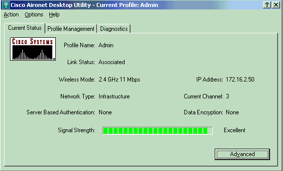
您可以檢查組態是否按預期運作。配置了SSID Admin的無線客戶端(管理員使用者)必須連線到VLAN 20。同一使用者應該能夠連線到有線網路上的管理員使用者,該有線網路也位於同一個VLAN上。若要驗證,請啟用管理員使用者的無線客戶端配置檔案。
注意:本文檔不解釋如何配置無線客戶端以設定配置檔案。有關如何配置無線客戶端介面卡的資訊,請參閱配置客戶端介面卡。
此示例視窗顯示無線客戶端與AP關聯:

AP上的show dot11 associations命令也會驗證客戶端是否已連線到VLAN 10:
註:Output Interpreter Tool(僅限註冊客戶)(OIT)支援某些show命令。使用OIT檢視show命令輸出的分析。
AccessPoint#show dot11 associations

802.11 Client Stations on Dot11Radio0:

SSID [Admin] :

MAC Address    IP address      Device        Name            Parent         State
0040.96ac.e657 172.16.2.50     CB21AG/PI21AG Admin User      self           Assoc
您可以在AP上發出show vlan命令,以顯示在AP上配置的VLAN。以下是範例:
AccessPoint#show vlans

Virtual LAN ID:  2 (IEEE 802.1Q Encapsulation)

   vLAN Trunk Interfaces:  Dot11Radio0.2
FastEthernet0.2

This is configured as native Vlan for the following interface(s) :
Dot11Radio0
FastEthernet0

   Protocols Configured:   Address:              Received:        Transmitted:
        Bridging        Bridge Group 1               1380                 712
        Other                                          0                  63

   0 packets, 0 bytes input
   733 packets, 50641 bytes output
        Bridging        Bridge Group 1               1380                 712
        Other                                          0                  63

   1381 packets, 98016 bytes input
   42 packets, 12517 bytes output

Virtual LAN ID:  20 (IEEE 802.1Q Encapsulation)

   vLAN Trunk Interfaces:  Dot11Radio0.20
FastEthernet0.20

   Protocols Configured:   Address:              Received:        Transmitted:
        Bridging        Bridge Group 20               798                 622
        Other                                          0                  19

   247 packets, 25608 bytes input
   495 packets, 43585 bytes output
        Bridging        Bridge Group 20               798                 622
        Other                                          0                  19

   552 packets, 37536 bytes input
   148 packets, 21660 bytes output

Virtual LAN ID:  30 (IEEE 802.1Q Encapsulation)

   vLAN Trunk Interfaces:  Dot11Radio0.30
FastEthernet0.30

   Protocols Configured:   Address:              Received:        Transmitted:
        Bridging        Bridge Group 30               693                 609
        Other                                          0                  19

   106 packets, 13373 bytes input
   517 packets, 48029 bytes output
        Bridging        Bridge Group 30               693                 609
        Other                                          0                  19

   605 packets, 47531 bytes input
   112 packets, 15749 bytes output
現在,您可以檢查無線管理員使用者是否能夠連線到為同一個VLAN配置的有線端上的管理員使用者。在無線客戶端上發出ping命令。以下是範例:
D:\>ping 172.16.2.60

Pinging 172.16.2.60 with 32 bytes of data:

Reply from 172.16.2.60: bytes=32 time<10ms TTL=255
Reply from 172.16.2.60: bytes=32 time<10ms TTL=255
Reply from 172.16.2.60: bytes=32 time<10ms TTL=255
Reply from 172.16.2.60: bytes=32 time<10ms TTL=255

Ping statistics for 172.16.2.60:
    Packets: Sent = 4, Received = 4, Lost = 0 (0% loss),
Approximate round trip times in milli-seconds:
    Minimum = 0ms, Maximum =  0ms, Average =  0ms
同樣地,您可以檢查訪客使用者是否連線到VLAN 30。您可以在訪客無線使用者端發出ping指令,測試與有線端的Web伺服器的連線。以下是範例:
D:\>ping 172.16.3.60

Pinging 172.16.3.60 with 32 bytes of data:

Reply from 172.16.3.60: bytes=32 time<10ms TTL=255
Reply from 172.16.3.60: bytes=32 time<10ms TTL=255
Reply from 172.16.3.60: bytes=32 time<10ms TTL=255
Reply from 172.16.3.60: bytes=32 time<10ms TTL=255

Ping statistics for 172.16.3.60:
    Packets: Sent = 4, Received = 4, Lost = 0 (0% loss),
Approximate round trip times in milli-seconds:
    Minimum = 0ms, Maximum =  0ms, Average =  0ms
疑難排解
使用本節內容,對組態進行疑難排解。
疑難排解程序
請依照以下說明進行操作,對組態進行疑難排解:
-
檢查在交換機埠上配置並連線到AP的本徵VLAN是否與AP的本徵VLAN匹配。
如果本徵VLAN不匹配,則不會通過交換機進行連線。
-
確保配置為中繼的交換機埠允許無線端上配置的所有VLAN。
預設情況下,允許所有VLAN通過TRUNK埠。
-
檢查bridge-group命令是否已在除本徵VLAN以外的所有VLAN上配置。
您無需在設定為本徵VLAN的子介面上配置網橋組。此網橋組會自動移動到本機子介面,以便保持到BVI 1的鏈路,BVI 1代表無線電介面和乙太網介面。
 注意:配置bridge-group命令時,將自動啟用這些命令:
bridge-group 10 subscriber-loop-control
bridge-group 10 block-unknown-source
no bridge-group 10 source-learning
no bridge-group 10 unicast-flooding
bridge-group 10 spanning-disabled
這些是標準預設設定,除非您得到指導,否則不應更改這些設定。如果移除這些命令,WLAN可能會無法按預期運作。
疑難排解指令
您也可以使用以下命令來疑難排解AP上的組態:
註:Output Interpreter Tool(僅限註冊客戶)(OIT)支援某些show命令。使用OIT檢視show命令輸出的分析。
-
show vlan
-
show vlan dot1q
-
show dot11 associations
在Catalyst 2950交換器上,您可以使用以下命令對組態進行疑難排解:
-
show vlan
-
show interface fastethernet x/x switchport
-
show interface fastethernet x/x trunk
在路由器上,發出以下命令可對組態進行疑難排解。
-
debug ip dhcp server packet
-
show ip interface brief
以下是在SSID Admin中為客戶端成功分配IP地址的輸出。
Router#debug ip dhcp server packet
*Nov 23 18:02:06.637: DHCPD: DHCPREQUEST received from client 0040.96ac.e657.

!--- Router receives the DHCP Request from the client

*Nov 23 18:02:06.637: DHCPD: No default domain to append - abort update
*Nov 23 18:02:06.637: DHCPD: Sending DHCPACK to client 0040.96ac.e657 (172.16.2.50).

!--- Router acknowledges the client's request

*Nov 23 18:02:06.637: DHCPD: creating ARP entry (172.16.2.2, 0040.96ac.e657).
*Nov 23 18:02:06.637: DHCPD: unicasting BOOTREPLY to client 0040.96ac.e657 (172.16.2.50).

!--- Router assigns ip address to the client from the VLAN 10 subnet
 注意:配置bridge-group命令時,將自動啟用這些命令:
 意見
意見