使用 Cisco Network Registrar 进行电缆调制解调器的基本安装
下载选项
非歧视性语言
此产品的文档集力求使用非歧视性语言。在本文档集中,非歧视性语言是指不隐含针对年龄、残障、性别、种族身份、族群身份、性取向、社会经济地位和交叉性的歧视的语言。由于产品软件的用户界面中使用的硬编码语言、基于 RFP 文档使用的语言或引用的第三方产品使用的语言,文档中可能无法确保完全使用非歧视性语言。 深入了解思科如何使用包容性语言。
关于此翻译
思科采用人工翻译与机器翻译相结合的方式将此文档翻译成不同语言,希望全球的用户都能通过各自的语言得到支持性的内容。 请注意:即使是最好的机器翻译,其准确度也不及专业翻译人员的水平。 Cisco Systems, Inc. 对于翻译的准确性不承担任何责任,并建议您总是参考英文原始文档(已提供链接)。
目录
简介
本技术说明的目的是为实验室环境中的电缆调制解调器(CM)网络提供完整的设置指南。此设置可作为部署到客户网络之前的第一步。请注意,实验中的无故障设置并不一定意味着客户网络中的无故障设置。在受控实验室环境中,噪音可能不是问题;而在现实生活中,情况可能恰恰相反。但是,此程序可用于排除Cisco IOS®软件版本、配置、硬件和射频(RF)所引起的问题。
先决条件
要求
本文档没有任何特定的要求。
使用的组件
本文档中的信息都是基于特定实验室环境中的设备编写的。本文档中使用的所有设备最初均采用原始(默认)配置。如果您使用的是真实网络,请确保您已经了解所有命令的潜在影响。
规则
有关文件规则的更多信息请参见“ Cisco技术提示规则”。
实验室拓扑结构
图1 — 实验网络设置 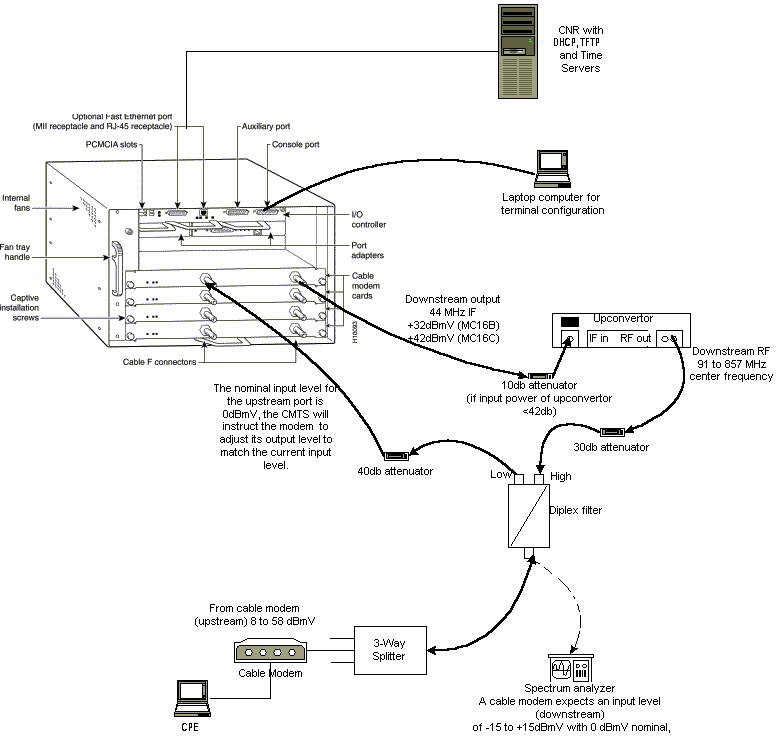
在此图中,电缆调制解调器端接系统(CMTS)由以下组件组成:
-
使用MC16C调制解调器卡运行Cisco IOS软件版本12.1(2)T的uBR7246
-
运行Cisco IOS软件版本12.0(7)T的CM uBR904
-
上变频器
-
双工滤波器,从低频分离高频
-
思科网络注册器(CNR)版本3.5(3)
-
三向分离器
-
客户端设备(CPE),在本例中为笔记本电脑
注意:该图中的RF设置可用作起始参考点;但是,在客户现场部署后,此情况可能会改变。RF测量超出本文档的范围;有关正确的RF设置和测量,请参阅将Cisco uBR7200系列路由器连接到电缆头端。
假设
-
上变频器已安装并正确配置。有关设置,请参阅供应商的文档。请记住,如果使用GI上变频器,应将其设置为比相关NTSC信道的中心频率低1.75 MHz。(请参阅使用频谱分析器获取DOCSIS下行信号的功率测量。)
-
在CM后面有一个配置正确的CPE,专门用于通过DHCP服务器获取IP地址。
-
CNR用作DHCP和TFTP服务器,具有相同的IP地址:172.17.110.136 的多播地址发送一次邻居消息。
-
一天中的时间(ToD)服务器软件与CNR在同一NT服务器上运行。
本文档的各节说明配置这些组件所需的步骤:
-
思科网络注册器(CNR)
-
有线数据服务接口规范(DOCSIS)配置文件
-
电缆调制解调器端接系统(CMTS)
-
电缆调制解调器(CM)
网络图
图2 — 包含本技术说明中使用的IP地址和名称的网络图 
Cisco Network Registrar 配置
按照以下步骤配置CNR:
-
从“开始”菜单启动CNR。
-
在菜单栏上,单击“添加”选项卡以添加新群集。
-
输入集群名称。
在本例中,IP地址用作名称。
-
选中“添加后连接到此群集”复选框。
-
Click OK.

-
-
当系统提示您输入用户名和密码时,请使用admin和changeme。
图4 - CNR中的用户名和密码窗口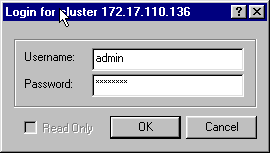
-
Click OK.
系统将显示一个类似于图5的窗口,该窗口包含已配置集群的名称或IP地址。
图5 - CNR中的“Server Manager(服务器管理器)”窗口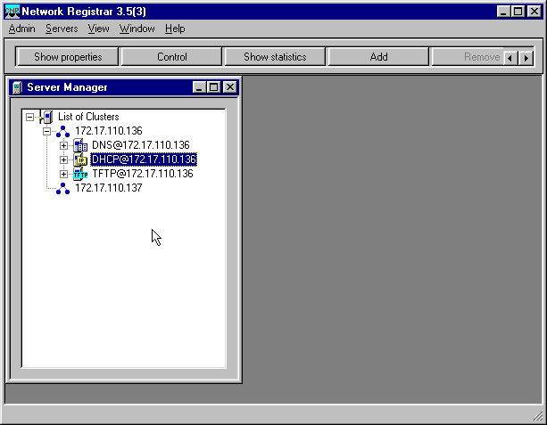
-
双击DHCP@172.17.110.136,打开DHCP@172.17.110.136属性窗口。
-
单击“策略”选项卡,然后单击“新建”以创建新策略。
图6 — 添加名为“Cable Modems”的策略并从“default”策略复制属性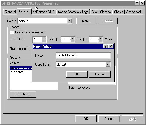
-
键入策略的名称。
在本示例中,名称为Cable Modems。
-
如果这是新策略,请将“复制自”字段设置为默认值。
-
Click OK.
-
单击Edit options,以指定DHCP选项。
对于名为“Cable Modems(电缆调制解调器)”的策略,添加以下选项(请参阅图7):
-
dhcp-lease-time默认处于活动状态,并设置为604800秒,即一周中的秒数。
-
路由器是CMTS电缆接口的IP地址,在本例中为10.1.1.10。请参阅配置头端(CMTS)。
-
CM与世界协调时(UTC)的时间偏移;CM使用此时间计算本地时间,以便时间戳错误日志。请参阅如何计算DHCP选项2的十六进制值(时间偏移)。
-
ToD服务器的时间服务器IP地址,即172.17.110.136。
-
packet-siaddr是TFTP服务器的IP地址,即172.17.110.136。
-
packet-file-name是使用DOCSIS CPE配置器配置的DOCSIS配置文件。此文件应位于TFTP服务器的tftpboot目录中。
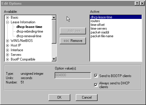
注意:如果有BOOTP客户端,请确保选中“发送到BOOTP客户端”复选框。还强烈建议您选中Always send to DHCP clients复选框。
-
-
创建与CM后的CPE关联的其他策略,如笔记本电脑等。
在本示例中,策略的名称为“电缆调制解调器客户端”。
按照与电缆调制解调器策略相同的步骤操作,但此时,将“复制自”字段设置为“电缆调制解调器”策略,而不是默认策略。
图8 — 添加名为“Cable Modem Clients”的策略,并从名为“Cable Modems”的现有策略复制属性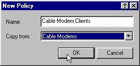
-
Click OK.
-
单击“编辑”选项按钮,选择活动选项。
-
对于CPE策略,从Active(活动)列表中删除除dhcp-lease-time和路由器选项之外的所有选项。
为此,请在“活动”列表中选择要删除的属性,然后单击“删除”按钮。
-
将路由器的IP地址选项更改为192.168.1.1,即CMTS路由器上配置的辅助IP地址。
请参阅配置头端(CMTS)。
图9 — 添加路由器属性的IP地址,该属性是在CMTS中应用此策略的电缆接口中配置的辅助IP地址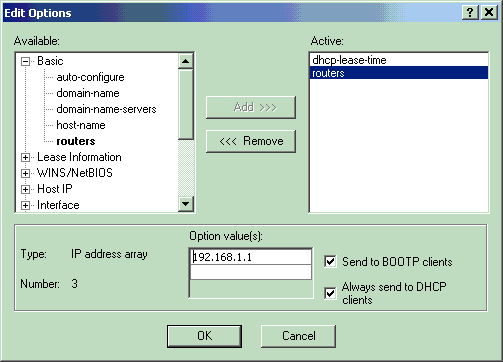
注意:本示例在CMTS和电缆调制解调器客户端策略中使用私有IP地址作为辅助地址。在生产环境中,CPE设备应使用公有IP地址,以便能够访问Internet(除非使用网络地址转换[NAT])。
-
创建范围以与电缆调制解调器和电缆调制解调器客户端策略关联。
-
要创建新范围,请单击主菜单中的DHCP@172.17.110.136,然后单击“Add(添加)”选项卡。
这将允许您添加新范围。
-
输入新范围的名称,然后选择适当的策略。
在本例中,电缆调制解调器的范围设置为使用10.1.1.20到10.1.1.30的IP地址。
图10 — 电缆调制解调器的范围,称为“电缆调制解调器”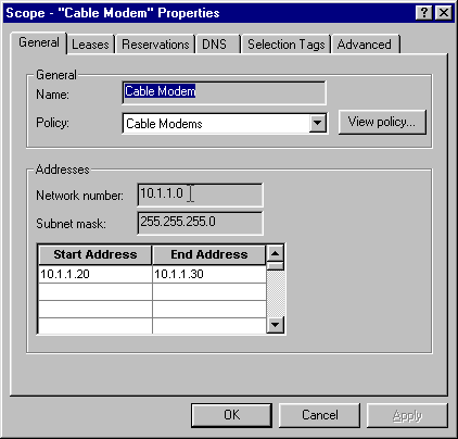
-
对“Cable Modem Clients(电缆调制解调器客户端)”范围重复步骤16a和16b。
在本例中,使用的私有IP地址范围为192.168.1.20到192.168.1.30。
图11 — 电缆调制解调器后的CPE设备范围,称为“电缆调制解调器客户端”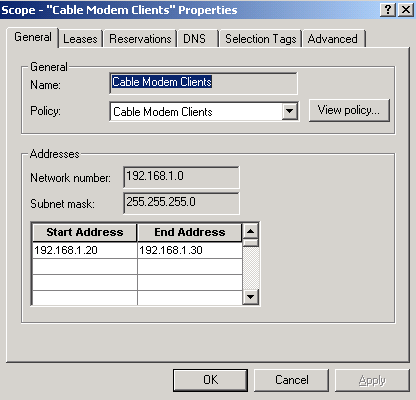
-
CPE设备使用的范围需要额外配置。
-
创建“Cable Modem Clients(电缆调制解调器客户端)”范围后,需要双击该范围以打开图12所示的对话框。
图12 — 电缆调制解调器客户端范围窗口
-
单击Advanced选项卡,将辅助范围与主范围关联。
-
勾选“使此范围成为辅助范围”复选框。
-
当下拉列表显示空值后,选择适当的主范围。
在本示例中,选择了Cable Modems范围。
图13 — 将“电缆调制解调器客户端”范围设置为次要范围并将其与主要范围关联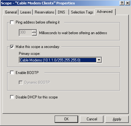
-
-
-
最后,您需要重新启动DHCP服务器,以便进行更改。
在主菜单中,选择DHCP@172.17.110.136,然后单击顶部的Control选项卡,以获取图14所示的对话框。通过此对话框,可以重新加载DHCP服务器。
图14 — 重新加载窗口以提交CNR中的更改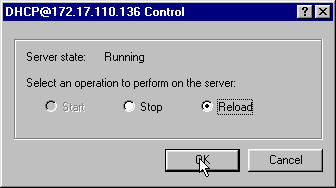
DOCSIS 配置文件
设置电缆网络所需的下一步是合成配置文件。要使电缆调制解调器联机,它需要通过TFTP从DHCP服务器下载其配置文件。在本文档示例中,CNR用于提供TFTP和DHCP服务器。有关设置配置文件的最低要求的详细信息,请参阅电缆调制解调器的DHCP和DOCSIS配置文件(DOCSIS 1.0)。文件是使用DOCSIS CPE配置器设置的。在本文档的CM(uBR904)部分中,使用的DOCSIS配置文件称为platinum.cm。
注意:创建配置文件后,请确保将其复制到TFTP服务器。对于CNR的TFTP服务器,您还必须确保TFTP服务器已启动:
-
选择TFTP@172.17.110.136,然后单击“Control(控制)”选项卡。
这将显示TFTP@172.17.110.136 Control对话框,其中可以启动服务器。
-
默认情况下,TFTP服务器功能处于关闭状态。要使TFTP服务器在启动时自动启动,请启动NRCMD(CNR的命令行界面)并发出以下命令:
server tftp set start-on-reboot=enabled

save
配置头端 (CMTS)
这是CMTS(uBR7246)的基本配置:
Current configuration:
!
version 12.1
service timestamps debug uptime
service timestamps log uptime
no service password-encryption
!
hostname Sydney
!
boot system flash ubr7200-ik1s-mz_121-2_T.bin
no logging buffered
enable password <deleted>
!
no cable qos permission create

!--- Default.

no cable qos permission update

!--- Default.

cable qos permission modems

!--- Default.

!
!
!
ip subnet-zero
no ip domain-lookup
!
!
interface FastEthernet0/0
 no ip address
 shutdown
 half-duplex
!
interface Ethernet1/0
 ip address 172.17.110.139 255.255.255.224

!--- The IP address of the interface in the same LAN segment as CNR.

!
interface Ethernet1/1
 no ip address
 shutdown
!
interface Ethernet1/2
 no ip address
 shutdown
!
interface Ethernet1/3
 no ip address
 shutdown
!
interface Ethernet1/4
 no ip address
 shutdown
!
interface Ethernet1/5
 no ip address
 shutdown
!
interface Ethernet1/6
 no ip address
 shutdown
!
interface Ethernet1/7
 no ip address
 shutdown
!
 interface Cable2/0
 ip address 192.168.1.1 255.255.255.0 secondary

!--- The secondary IP address is used for the CPE’s scope in CNR.

 ip address 10.1.1.10 255.255.255.0

!--- The primary IP address is used for the CM’s scope in CNR.

 no keepalive
 cable downstream annex B

!--- Default for DOCSIS-compliant cable plants. For EuroDOCSIS, use annex A.

 cable downstream modulation 64qam

!--- Default.

 cable downstream interleave-depth 32

!--- Default.

 cable downstream frequency 451250000

!--- Cosmetic except for the uBR7100. This line has no effect !--- on Upconverter Frequency. Used as a reminder of the frequency !--- that is used in the Unconverter.

 cable upstream 0 frequency 28000000

!--- Upstream Frequency configuration. This is chosen after a careful !--- analysis on the noise levels of the return path.

 cable upstream 0 power-level 0
 no cable upstream 0 shutdown

!--- Enables the upstream 0 port.

 cable upstream 1 shutdown
 cable upstream 2 shutdown
 cable upstream 3 shutdown
 cable upstream 4 shutdown
 cable upstream 5 shutdown
 cable dhcp-giaddr policy

!--- Modifies the GIADDR field of DHCPDISCOVER and DHCPREQUEST packets.

 cable helper-address 172.17.110.136

!--- Specifies a destination IP address for UDP-broadcast DHCP packets.

!
interface Cable3/0
 no ip address
 no keepalive
 shutdown
 cable downstream annex B
 cable downstream modulation 64qam
 cable downstream interleave-depth 32
 cable upstream 0 shutdown
 cable upstream 1 shutdown
 cable upstream 2 shutdown
 cable upstream 3 shutdown
 cable upstream 4 shutdown
 cable upstream 5 shutdown
!
ip classless
ip route 0.0.0.0 0.0.0.0 172.17.110.129
no ip http server
!
line con 0
 exec-timeout 0 0
 transport input none
line aux 0
line vty 0
 exec-timeout 0 0
  transport input none
line aux 0
line vty 0
 exec-timeout 0 0
 password cisco
 login
line vty 1 4
 password cisco
 login
!
end
配置 CM
通常,电缆调制解调器不需要任何用户配置即可上线(除出厂默认设置外)。 这仅在CM用作网桥时适用。以下是在CM联机后自动获取的uBR电缆调制解调器配置示例:
version 12.0
no service pad
service timestamps debug uptime
service timestamps log uptime
no service password-encryption
!
hostname Router
!
clock timezone - 0
ip subnet-zero
no ip routing
!
!
interface Ethernet0
 ip address 10.1.1.25 255.255.255.0
 no ip directed-broadcast
 no ip route-cache
 bridge-group 59
 bridge-group 59 spanning-disabled
!
interface cable-modem0
 ip address negotiated
 no ip directed-broadcast
 no ip route-cache
 cable-modem downstream saved channel 453000000 20 1
 cable-modem mac-timer t2 40000
 bridge-group 59
 bridge-group 59 spanning-disabled
!
ip default-gateway 10.1.1.10
ip classless
no ip http server
!
!
line con 0
 transport input none
line vty 0 4
!
end
验证和故障排除
本节介绍可用于检验电缆网络是否正常运行的命令。
在CMTS(uBR7246)上
确保电缆调制解调器处于在线状态:
Sydney# show cable modem

Interface   Prim Online     Timing Rec    QoS CPE IP address      MAC address
            Sid  State      Offset Power
Cable2/0/U0 2    online     2290   -0.25  6   1   10.1.1.25       0050.7366.2223
如果电缆调制解调器处于init(d)状态,则CMTS电缆的接口与DHCP服务器之间没有连接。
确保您可以从CMTS的电缆接口发出扩展ping:
Sydney# ping ip

Target IP address: 172.17.110.136
Repeat count [5]:
Datagram size [100]:
Timeout in seconds [2]:
Extended commands [n]: y
Source address or interface: 10.1.1.10
Type of service [0]:
Set DF bit in IP header? [no]:
Validate reply data? [no]:
Data pattern [0xABCD]:
Loose, Strict, Record, Timestamp, Verbose[none]:
Sweep range of sizes [n]:
Type escape sequence to abort.
Sending 5, 100-byte ICMP Echos to 172.17.110.136, timeout is 2 seconds:
!!!!!
Success rate is 100 percent (5/5), round-trip min/avg/max = 8/12/24 ms
如果ping不成功,请检查IP路由。此外,确保运行CNR的NT服务器具有正确的默认网关或路由回CMTS。您还可以从CNR发出ping。
在CMTS上可用于验证电缆调制解调器和CPE连接的另一个命令是show interface cable 2/0 modem 0:
Sydney# show interfaces cable 2/0 modem 0

SID   Priv bits  Type      State     IP address    method    MAC address
2     00         host      unknown   192.168.1.20  dhcp      0010.a4e6.d04d

!--- A laptop that is obtaining an IP address.

2     00         modem     up        10.1.1.25     dhcp      0050.7366.2223

!--- The cable modem.
在CM(uBR904)上
您还可以检查电缆调制解调器端的连接。发出show ip interface brief命令并检查接口是否处于up/up:
Router# show ip interface brief

Interface                  IP-Address      OK? Method Status         Protocol
Ethernet0                  10.1.1.25       YES unset  up             up
cable-modem0               10.1.1.25       YES unset  up             up

Router# show controllers cable-modem 0

BCM Cable interface 0:
CM unit 0, idb 0x2010AC, ds 0x86213E0, regaddr = 0x800000, reset_mask 0x80
station address 0050.7366.2223  default station address 0050.7366.2223
PLD VERSION: 32
MAC State is maintenance_state, Prev States = 15
MAC mcfilter 01E02F00  data mcfilter 01000000
MAC extended header ON
DS: BCM 3116 Receiver: Chip id = 2
US: BCM 3037 Transmitter: Chip id = 30AC
Tuner: status=0x00
Rx: tuner_freq 453000000, symbol_rate 5055880, local_freq 11520000
    snr_estimate 35210, ber_estimate 0, lock_threshold 26000
    QAM in lock, FEC in lock, qam_mode QAM_64
Tx: TX_freq 27984000, power_level 0x30 (24.0 dBmV), symbol_rate 8
    (1280000 sym/sec)
DHCP: TFTP server = 172.17.110.136, TOD server = 172.17.110.136
      Security server = 0.0.0.0, Timezone Offest = 0
      Config filename = platinum.cm
buffer size 1600

RX data PDU ring with 32 entries at 0x202130
   rx_head = 0x202168 (7), rx_p = 0x8621418 (7)

RX MAC message ring with 8 entries at 0x202270
  rx_head_mac = 0x2022A0 (6), rx_p_Mac = 0x86214BC (6)

TX BD ring with 8 entries at 0x2023A8, TX_count = 0
  TX_head = 0x2023C8 (4), head_txp = 0x8621548 (4)
  TX_tail = 0x2023C8 (4), tail_txp = 0x8621548 (4)

TX PD ring with 8 entries at 0x202428, TX_count = 0
  TX_head_pd = 0x202C28 (4)
  TX_tail_pd = 0x202C28 (4)

Global control and status:
  global_ctrl_status=0x00
interrupts:
  irq_pend=0x0008, irq_mask=0x00F7
您还可以测试IP连接。从CM对DHCP服务器执行ping操作:
Router# ping 172.17.110.136

Type escape sequence to abort.
Sending 5, 100-byte ICMP Echos to 172.17.110.136, timeout is 2 seconds:
!!!!!
Success rate is 100 percent (5/5), round-trip min/avg/max = 8/12/24 ms
uBR7246
Sydney# show version

Cisco Internetwork Operating System Software
IOS (tm) 7200 Software (UBR7200-IK1S-M),
     Version 12.1(2)T, RELEASE SOFTWARE (fc1)
Copyright (c) 1986-2000 by cisco Systems, Inc.
Compiled Tue 16-May-00 13:36 by ccai
Image text-base: 0x60008900, data-base: 0x613E8000
ROM: System Bootstrap,
     Version 11.1(10) [dschwart 10], RELEASE SOFTWARE (fc1)
BOOTFLASH: 7200 Software (UBR7200-BOOT-M),
     Version 12.0(10)SC, EARLY DEPLOYMENT RELEASE SOFTWARE (fc1)
Sydney uptime is 4 days, 40 minutes
System returned to ROM by reload
System image file is "slot0:ubr7200-ik1s-mz_121-2_T.bin"
cisco uBR7223 (NPE150) processor (revision B) with 57344K/8192K bytes of memory.
Processor board ID SAB0249006T
R4700 CPU at 150Mhz, Implementation 33, Rev 1.0, 512KB L2 Cache
3 slot midplane, Version 1.0
Last reset from power-on
Bridging software.
X.25 software, Version 3.0.0.
8 Ethernet/IEEE 802.3 interface(s)
1 FastEthernet/IEEE 802.3 interface(s)
2 Cable Modem network interface(s)
125K bytes of non-volatile configuration memory.
1024K bytes of packet SRAM memory.
20480K bytes of Flash PCMCIA card at slot 0 (Sector size 128K).
4096K bytes of Flash internal SIMM (Sector size 256K).
Configuration register is 0x2102
uBR904
Router# show version

Cisco Internetwork Operating System Software
IOS (TM) 900 Software (UBR900-K1OY556I-M),
     Version 12.0(7)T,  RELEASE SOFTWARE (fc2)
Copyright (c) 1986-1999 by cisco Systems, Inc.
Compiled Tue 07-Dec-99 02:01 by phanguye
Image text-base: 0x08004000, database: 0x0852E888


ROM: System Bootstrap,
     Version 11.2(19980518:195057), RELEASED SOFTWARE
ROM: 900 Software (UBR900-RBOOT-M),
     Version 11.3(7)NA, EARLY DEPLOYMENT RELEASE SOFTWARE (fc1)


Router uptime is 1 hour, 6 minutes
System returned to ROM by reload at 11:20:43 - Thu Oct 12 2001
System restarted at 11:21:53 - Thu Oct 12 2001
System image file is "flash:ubr900-k1oy556i-mz.120-7.T.bin"

cisco uBR900 CM (68360) processor (revision D) with 8192K bytes of memory.
Processor board ID FAA0315Q07M
Bridging software.
1 Ethernet/IEEE 802.3 interface(s)
1 Cable Modem network interface(s)
4096K bytes of processor board System flash (Read/Write)
2048K bytes of processor board Boot flash (Read/Write)


Configuration register is 0x2102
 反馈
反馈