基本的な DLSw+ 構成
内容
概要
DLSw は、IBM Systems Network Architecture(SNA; システム ネットワーク アーキテクチャ)と IBM NetBIOS トラフィックを IP ネットワーク上で転送するときに使用するスイッチ間プロトコルです。このプロトコルは完全なルーティングを行うものではなく、インターネット上での転送の際に、SNA データリンク層のスイッチングと TCP/IP でのカプセル化を提供します。
はじめに
表記法
ドキュメント表記の詳細は、『シスコ テクニカル ティップスの表記法』を参照してください。
前提条件
このドキュメントに関しては個別の前提条件はありません。
使用するコンポーネント
このドキュメントの内容は、特定のソフトウェアやハードウェアのバージョンに限定されるものではありません。
このマニュアルの情報は、特定のラボ環境に置かれたデバイスに基づいて作成されました。このドキュメントで使用するすべてのデバイスは、初期(デフォルト)設定の状態から起動しています。実稼動中のネットワークで作業をしている場合、実際にコマンドを使用する前に、その潜在的な影響について理解しておく必要があります。
背景説明
DLSw+ は、シスコ独自の DLSw 実装です。DLSw+ には、DLSw 標準に加えて次の機能があります。
-
転送オプションの選択(TCP、Fast-Sequenced Transport(FST)、および直接カプセル化など)
-
スケーラビリティ機能拡張:(ピア グループ、オンデマンド ピア、探索ファイアウォール、ロケーション ラーニングなどによる)
-
ローカルおよびリモートの LAN と SDLC またはイーサネットの間のメディア変換
DLSw 標準について
DLSw 標準の詳細は、RFC 1795 を参照してください(RFC 1795 の登場により、RFC 1434 は廃止されました)。 要約すると、RFC 1795 では、DLSw 接続の確立、リソースの位置確認、データの転送、フロー制御の処理、およびエラーの復旧などを行うために、ルータ間で使用される Switch-to-Switch Protocol(SSP; スイッチ間プロトコル)について説明しています。また、Data Link Control(DLC; データリンク コントロール層)接続をローカルで終端する方法、および DLC 接続を DLSw 回線にマッピングする方法についても説明しています。
DLC 接続がローカルで終端されると、DLSw では次の問題が処理されます。
-
DLC のタイムアウト
-
WAN 上での DLC の確認応答
-
フローおよび輻輳の制御
-
検索パケットのブロードキャスト制御
-
ソース ルート ブリッジングのホップ カウントの制限
注:RFC 1795の機能拡張は、RFC 2166で確認できます。これらの機能拡張は、DLSw のスケーラビリティの問題と RFC 1795 の明確化に対処するためのものです。ただし、RFC 2166 は RFC 1795 を廃止していないため、RFC 1795 と併せて使用する必要があります。
サンプル設定
ここで説明する設定は全体的設定の一部です。これらの設定は、DLSw+ のサポートに必要な設定の部分を説明するものであり、IP や他のプロトコルではサポートされません。DLSw+ は、TCP/IP に依存しているので(FST または直接カプセル化を使用する場合は除く)、IP ネットワークがすでに起動して稼動していることを想定しています。
1. Token Ring to Token Ring over WAN

Router A

!
source-bridge ring-group 2000
dlsw local-peer peer-id 150.150.1.1
dlsw remote-peer 0 tcp 150.150.2.1
!
interface Loopback0
 ip address 150.150.1.1 255.255.255.0
!
interface Serial0
 ip address 150.150.100.1 255.255.255.0
!
interface TokenRing0
 ip address 150.150.10.1 255.255.255.0
 ring-speed 16
 source-bridge 1 1 2000
 source-bridge spanning

 !--- Allows the router to forward single route explorer frames.
Router B

!
source-bridge ring-group 2000
dlsw local-peer peer-id 150.150.2.1
dlsw remote-peer 0 tcp 150.150.1.1
!
interface Loopback0
 ip address 150.150.2.1 255.255.255.0
!
interface Serial0
 ip address 150.150.100.2 255.255.255.0
!
interface TokenRing0
 ip address 150.150.20.2 255.255.255.0
 ring-speed 16
 source-bridge 2 1 2000
 source-bridge spanning

 !--- Allows the router to forward single route explorer frames.
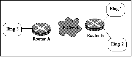
この例では、1 つの仮想リング(リング番号 2000)を選んで、2 つのグループ間に簡単に接続を確立しました。ただし、ルーティング情報フィールド(RIF)は DLSw+ のルータで終端しています。ルータごとに、異なる仮想リング番号を選択できます。リング番号は慎重に選択してください。ソースルート ブリッジングに適用するルールと同じルールに従う必要があります。シスコでは、現在、ルータごとに 1 つの仮想リングだけをサポートしています。
dlsw local-peer コマンドは、ローカル ルータに DLSw+ IP アドレスを定義するときに使用します。上の例では、DLSw+ が動作中の実際の物理インターフェイスに依存しなくても済むように、ループバック インターフェイスの IP アドレスを使用しています。
dlsw remote-peer コマンドは、リモート ルータの IP アドレスを定義します。remote-peer キーワードの後ろにある数字の 0 は、リングリスト の番号です。一般に、フルメッシュ構造のネットワークを使用する場合は、番号0を使用します。リングリスト番号は、ネットワークをセグメント化することによって探索フレームのフラッディングを制御するために使用されます(リングリストのデモの例2を参照してください)。
2. Token Ring to Token Ring with Ring-list

Router A

!
source-bridge ring-group 2000
dlsw local-peer peer-id 150.150.1.1
dlsw remote-peer 0 tcp 150.150.2.1
!
interface Loopback0
 ip address 150.150.1.1 255.255.255.0
!
interface Serial0
 ip address 150.150.100.1 255.255.255.0
!
interface TokenRing0
 ip address 150.150.10.1 255.255.255.0
 ring-speed 16
 source-bridge 3 1 2000
 source-bridge spanning

 !--- Allows the router to forward single route explorer frames.
Router B
!
source-bridge ring-group 2000
dlsw local-peer peer-id 150.150.2.1
dlsw remote-peer 1 tcp 150.150.1.1
dlsw ring-list 1 rings 1
!
interface Loopback0
 ip address 150.150.2.1 255.255.255.0
!
interface Serial0
 ip address 150.150.100.2 255.255.255.0
!
interface TokenRing0
 ip address 150.150.20.2 255.255.255.0
 ring-speed 16
 source-bridge 1 1 2000
 source-bridge spanning

 !--- Allows the router to forward single route explorer frames.

!
interface TokenRing1
ip address 150.150.30.1 255.255.255.0
ring-speed 16
source-bridge 2 1 2000
source bridge spanning

 !--- Allows the router to forward single route explorer frames.
この例では、リング 3 上の全ワークステーションは、リング 1 上の端末とはセッションを確立できますが、リング 2 の端末とはできません。反対方向に接続する場合も同様です。リング 1 の端末とリング 2 の端末は、両方ともルータ B とローカルで接続しているので、互いに通信ができます。
これは、ルータAに配信されるリング2からのブロードキャストがないことを意味します。dlsw ring-list、port-list、およびbgroup-list文を使用すると、WAN経由でブロードキャストトラフィックを制御する場合に非常に便利です。
3. Token Ring to Ethernet over WAN

この例では、デバイスのあるメディアが混在しているので、探索テスト パケットを開始するセカンダリ デバイスによってホストの MAC アドレスが符号化される前に、このアドレスをビットスワップする必要があります。詳細は、「ソースルート トランスレーショナル ブリッジングの概要とトラブルシューティング」も参照してください。
Router A

!
source-bridge ring-group 2000
dlsw local-peer peer-id 150.150.1.1
dlsw remote-peer 0 tcp 150.150.2.1
!
interface Loopback0
 ip address 150.150.1.1 255.255.255.0
!
interface Serial0
 ip address 150.150.100.1 255.255.255.0
!
interface TokenRing0
 ip address 150.150.10.1 255.255.255.0
 ring-speed 16
 source-bridge 1 1 2000
 source-bridge spanning
 !--- Allows the router to forward single route explorer frames.
次の例では、イーサネット セグメント上の端末が、トークン リング セグメント上の端末と通信できます。DLSw+ ルータは、イーサネット形式からトークン リング形式への変換を行います。dlsw bridge-group コマンドは、source-bridge 文が仮想のリンググループによってトークン リングのセグメントと DLSw+ を接続するようのと同じように、イーサネット セグメントを DLSw+ プロセスに接続します。ルータ B にトークン リングのインターフェイスがなく、このトークン リングの端末とイーサネットの端末間の通信が必要でない場合、SRT/LB を構成する必要はありません。例 6」を参照してください。
注: ルータ B 上では、source-bridge ring-group は必要ありません。
Router B
!
dlsw local-peer peer-id 150.150.2.1
dlsw remote-peer 0 tcp 150.150.1.1
dlsw bridge-group 1
!
interface Loopback0
 ip address 150.150.2.1 255.255.255.0
!
interface Serial0
 ip address 150.150.100.2 255.255.255.0
!
interface Ethernet0
 ip address 150.150.30.1 255.255.255.0
 bridge-group 1
!
bridge 1 protocol dec
!
4. Ethernet to Ethernet over WAN

Router A
!
dlsw local-peer peer-id 150.150.1.1
dlsw remote-peer 0 tcp 150.150.2.1
dlsw bridge-group 1
!
interface Loopback0
 ip address 150.150.1.1 255.255.255.0
!
interface Serial0
 ip address 150.150.100.1 255.255.255.0
!
interface Ethernet0
 ip address 150.150.30.1 255.255.255.0
 bridge-group 1
!
bridge 1 protocol dec
!
Router B
!
dlsw local-peer peer-id 150.150.2.1
dlsw remote-peer 0 tcp 150.150.1.1
dlsw bridge-group 1
!
interface Loopback0
 ip address 150.150.2.1 255.255.255.0
!
interface Serial0
 ip address 150.150.100.2 255.255.255.0
!
interface Ethernet0
 ip address 150.150.40.1 255.255.255.0
 bridge-group 1
!
bridge 1 protocol dec
注: source-bridge ring-group は、どちらのルータにも必要ありません。
5. Token Ring to Ethernet in the Same Router

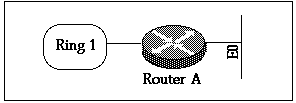
イーサネットとトークン リング間に位置しており、ルータに対してローカルである端末を接続する必要がある場合は、SR/TLB(トランスレーショナル ブリッジング)を使用する必要があります。 イーサネットとトークン リング間のローカル DLSw はサポートされません。
Router A

source-bridge ring-group 2000
source-bridge transparent 2000 1000 1 1

interface Ethernet0
 ip address 150.150.40.1 255.255.255.0
 bridge-group 1
!
interface TokenRing0
 ip address 150.150.10.1 255.255.255.0
 ring-speed 16
 source-bridge 1 1 2000
 source-bridge spanning
 !--- Allows the router to forward single route explorer frames.

!
bridge 1 protocol ieee
次にsource-bridge transparent 2000 1000 1 1 コマンドを説明します。
-
2000 は、source-bridge ring-group 2000 によって設定する仮想リング番号です。
-
1000 は、イーサネット ドメインに提供される仮のリング番号です。
-
1 は、透過型ブリッジング ドメインと接続しているブリッジのブリッジ番号です。
-
1 は、ソースルート ブリッジング ドメインと接続する、透過的なbridge-group の番号です。
注:インターフェイスのIPアドレスはSRT/LBには必要ありません。
6. SR/TLB and DLSw+

Router A
source-bridge ring-group 2000
source-bridge transparent 2000 1000 1 1
dlsw local-peer peer-id 150.150.1.1
dlsw remote-peer 0 tcp 150.150.2.1
dlsw bridge-group 1
!
interface Loopback0
 ip address 150.150.1.1 255.255.255.0
!
interface Ethernet0
 ip address 150.150.40.1 255.255.255.0
 bridge-group 1
!
interface TokenRing0
 ip address 150.150.10.1 255.255.255.0
 ring-speed 16
 source-bridge 1 1 2000
 source-bridge spanning
 !--- Allows the router to forward single route explorer frames.

!
bridge 1 protocol dec
Router B
source-bridge ring-group 2000
dlsw local-peer peer-id 150.150.2.1
dlsw remote-peer 0 tcp 150.150.1.1
!
interface Loopback0
 ip address 150.150.2.1 255.255.255.0
!
interface TokenRing0
 ip address 150.150.11.1  255.255.255.0
 ring-speed 16
 source-bridge 2 1 2000
 source-bridge spanning
 !--- Allows the router to forward single route explorer frames.
上の例では、DLSw と SRT/LTB の両方が構成されています。SRT/LBが必要なのは、トークンリング上のステーションが同じルータAのイーサネット上のステーションと通信する必要がある場合だけです。ルータAのイーサネットステーションがルータBのリモートのトークンリングステーションと通信する場合は、dlsw bridge-group 1です。
7. Token Ring to SDLC over WAN

Router A
!
source-bridge ring-group 2000
dlsw local-peer peer-id 150.150.1.1
dlsw remote-peer 0 tcp 150.150.2.1
!
interface Loopback0
 ip address 150.150.1.1 255.255.255.0
!
interface Serial0
 ip address 150.150.100.1 255.255.255.0
!
interface TokenRing0
 ip address 150.150.10.1 255.255.255.0
 ring-speed 16
 source-bridge 1 1 2000
 source-bridge spanning
 !--- Allows the router to forward single route explorer frames.


Router B

dlsw local-peer peer-id 150.150.2.1
dlsw remote-peer 0 tcp 150.150.1.1
!
interface Loopback0
 ip address 150.150.2.1 255.255.255.0
!
interface Serial0
 ip address 150.150.100.2 255.255.255.0
!
interface Serial 1
 no ip address
 encapsulation sdlc
 no keepalive
 clockrate 9600
 sdlc role primary

 !--- Assumes SDLC station role secondary for the controller.

 sdlc vmac 4000.9999.0100

 !--- Virtual MAC address given to the controller which will !--- have sdlc address (01) appended to it.

 sdlc address 01

 !--- SDLC address, obtained from controller configuration.

 sdlc xid 01 05D20001

 !--- 01 is the SDLC address and IDBLK/IDNUM should match that !--- in SMN on the host.

 sdlc partner 4000.1020.1000 01

 !--- 4000.1020.1000 is the MAC address of the host !--- and 01 is the SDLC address.

 sdlc dlsw 1
!
注:DLSw回線接続は4000.9999.0101と4000.1020.1000の間になります。また、上記の例ではPU2.0コントローラを想定しています。その他の PU タイプについては、「DLSw SDLC トラブルシューティング ガイド」を参照してください。
上の構成例は、一般的なネットワーク シナリオです。DLSw+ では多くのことができますが、前述の構成例では、基本を説明しています。DLSw+ は拡張 RSRB であり、RFC 1795 および 2166 に準拠する、他のルータとの相互運用性の機能が追加されていることに留意してください。
 フィードバック