Introduction
This document describes how to set up a WLAN with 802.1X security on a Cisco Catalyst 9800 Series Wireless Controller.
Prerequisites
Requirements
Cisco recommends that you have knowledge of these topics:
Components Used
The information in this document is based on these software and hardware versions:
- Catalyst 9800 Wireless Controller Series (Catalyst 9800-CL)
- Cisco IOS® XE Gibraltar 17.3.x
- Cisco ISE 3.0
The information in this document was created from the devices in a specific lab environment. All of the devices used in this document started with a cleared (default) configuration. If your network is live, ensure that you understand the potential impact of any command.
Configure
Network Diagram
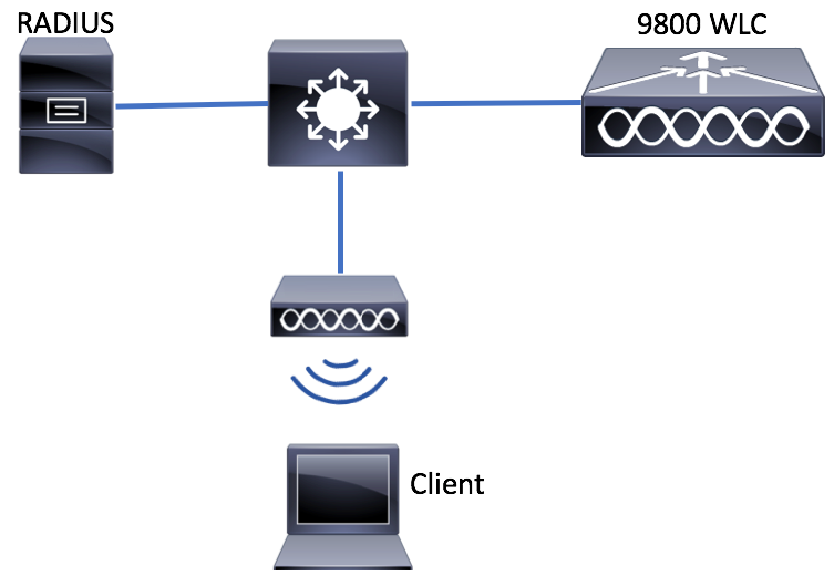
WLC Configuration
AAA Configuration on 9800 WLCs
GUI:
Step 1. Declare RADIUS server. Navigate to Configuration > Security > AAA > Servers / Groups > RADIUS > Servers > + Add and enter the RADIUS server information.
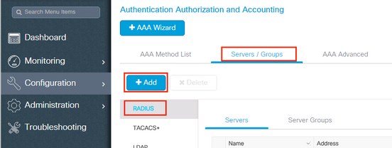
Ensure Support for CoA is enabled if you plan to use Central Web Authentication (or any kind of security that requires Change of Authorization [CoA]) in the future.
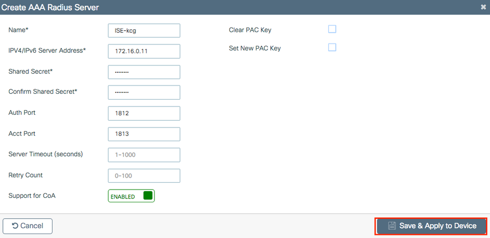
Step 2. Add the RADIUS server to a RADIUS group. Navigate to Configuration > Security > AAA > Servers / Groups > RADIUS > Server Groups > + Add. Give a name to your group and move the server you created earlier in the list of Assigned Servers.
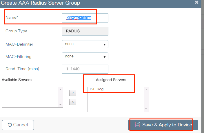
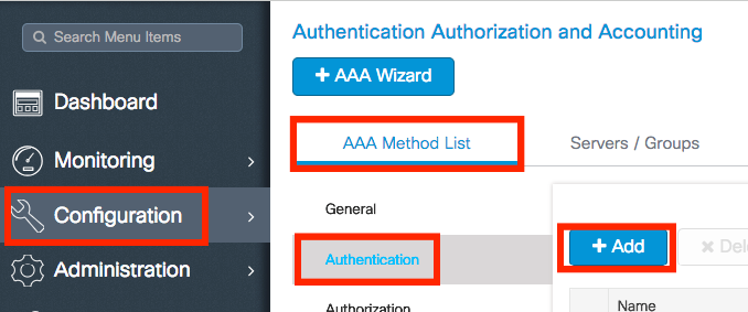
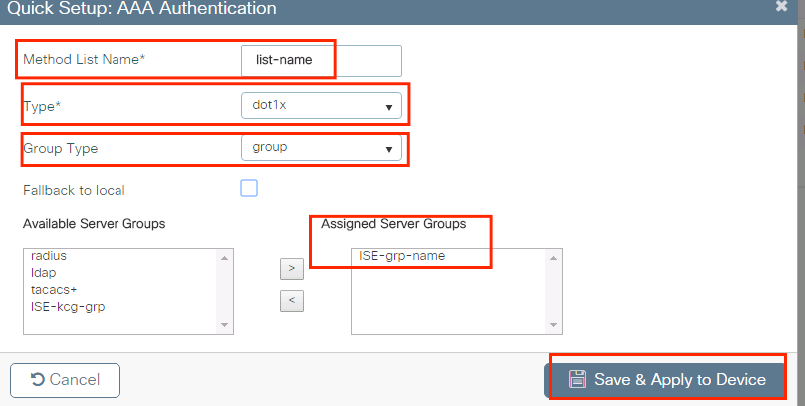
Step 3. Create an Authentication Method List. Navigate to Configuration > Security > AAA > AAA Method List > Authentication > + Add.
Enter the information:
CLI:
# config t
# aaa new-model

# radius server <radius-server-name>
# address ipv4 <radius-server-ip> auth-port 1812 acct-port 1813
# timeout 300
# retransmit 3
# key <shared-key>
# exit

# aaa group server radius <radius-grp-name>
# server name <radius-server-name>
# exit

# aaa server radius dynamic-author
# client <radius-server-ip> server-key <shared-key>

# aaa authentication dot1x <dot1x-list-name> group <radius-grp-name>
Note on the AAA Dead-Server Detection
After you have configured your RADIUS server, you can check if it is considered as "ALIVE":
#show aaa servers | s WNCD
     Platform State from WNCD (1) : current UP
     Platform State from WNCD (2) : current UP
     Platform State from WNCD (3) : current UP
     Platform State from WNCD (4) : current UP
     ...
You can configure the dead criteria, as well as the deadtime on your WLC, especially if you use multiple RADIUS servers.
#radius-server dead-criteria time 5 tries 3
#radius-server deadtime 5
Note: The dead criteria is the criteria used to mark a RADIUS server as dead. It consists of: 1. A timeout (in seconds) which represents the amount of time that must elapse from the time the controller last received a valid packet from the RADIUS server to the time the server is marked as dead. 2. A counter, which represents the number of consecutive timeouts that must occur on the controller before the RADIUS server is marked as dead.
Note: The deadtime specifies the amount of time (in minutes) the server remains in dead status after dead-criteria marks it as dead. Once the deadtime expires, the controller marks the server as UP (ALIVE) and notifies the registered clients about the state change. If the server is still unreachable after the state is marked as UP and if the dead criteria is met, then server is marked as dead again for the deadtime interval.
WLAN Profile Configuration
GUI:
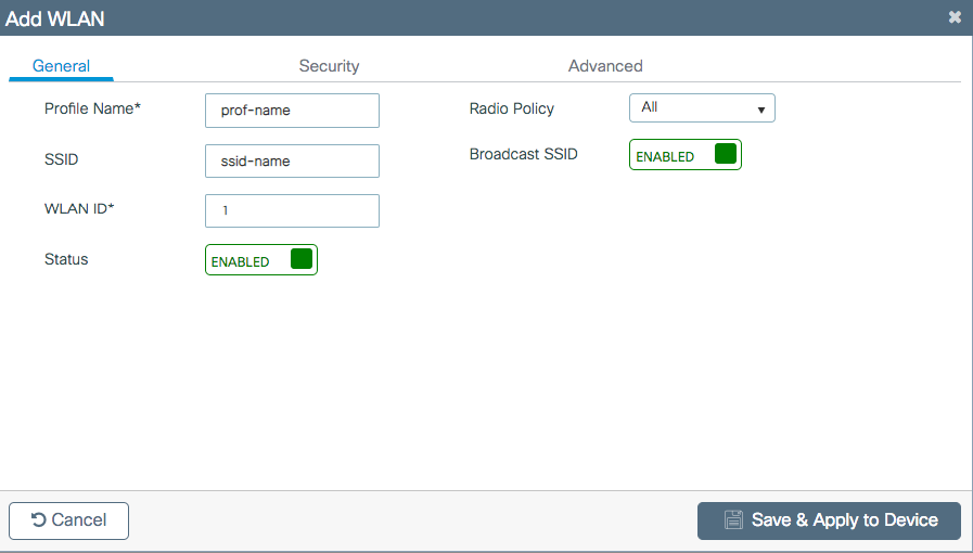
Step 1. Create the WLAN. Navigate to Configuration > Wireless > WLANs > + Add and configure the network as needed.

Step 2. Enter the WLAN information
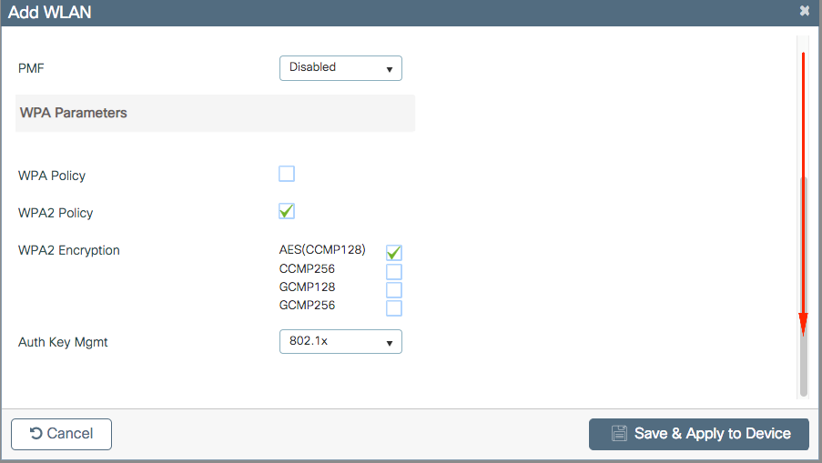
Step 3. Navigate to the
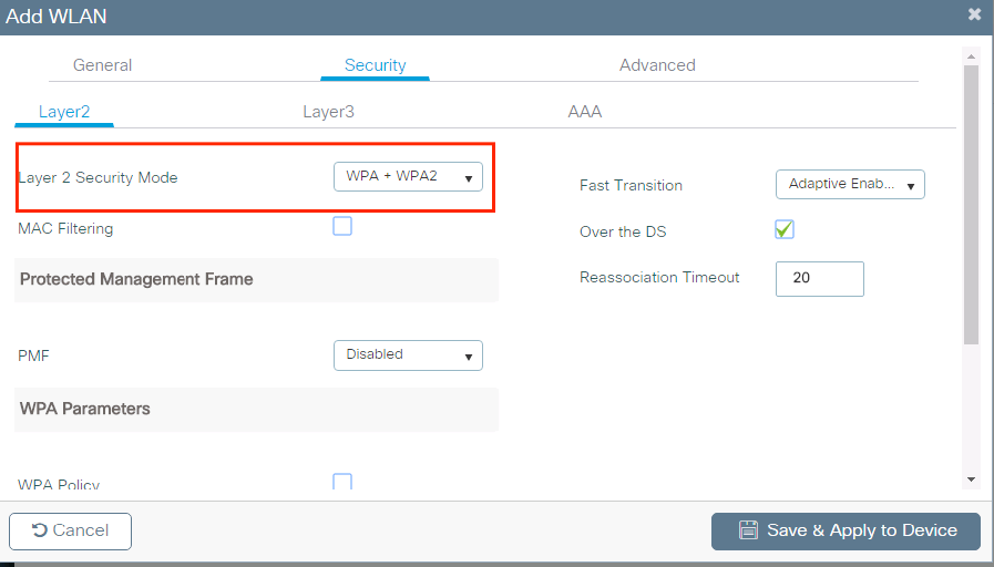
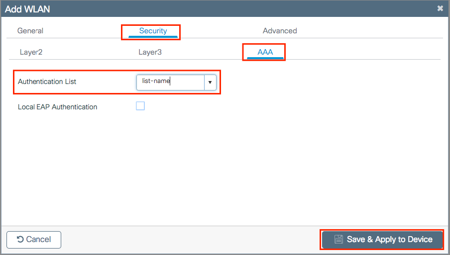
Step 4. From the Security > AAA tab, select the authentication method created on Step 3 from AAA Configuration on 9800 WLC section.
CLI:
# config t
# wlan <profile-name> <wlan-id> <ssid-name>
# security dot1x authentication-list <dot1x-list-name>
# no shutdown
Policy Profile Configuration
Inside a Policy Profile you can decide to which VLAN to assign the clients, among other settings (like Access Controls List [ACLs], Quality of Service [QoS], Mobility Anchor, Timers, and so on).
You can either use your default policy profile or you can create a new profile.
GUI:
Navigate to Configuration > Tags & Profiles > Policy Profile and either configure your default-policy-profile or create a new one.

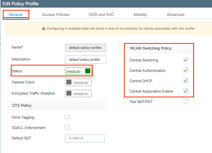
Ensure the profile is enabled.
Also, if your Access Point (AP) is in local mode, ensure the policy profile have Central Switching and Central Authentication enabled.
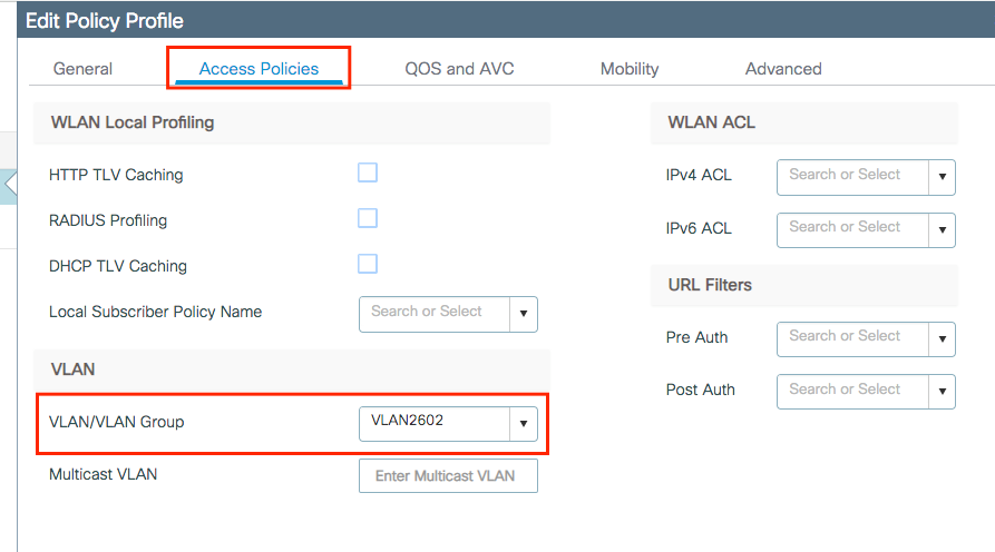
Select the VLAN where the clients need to be assigned in the Access Policies tab.
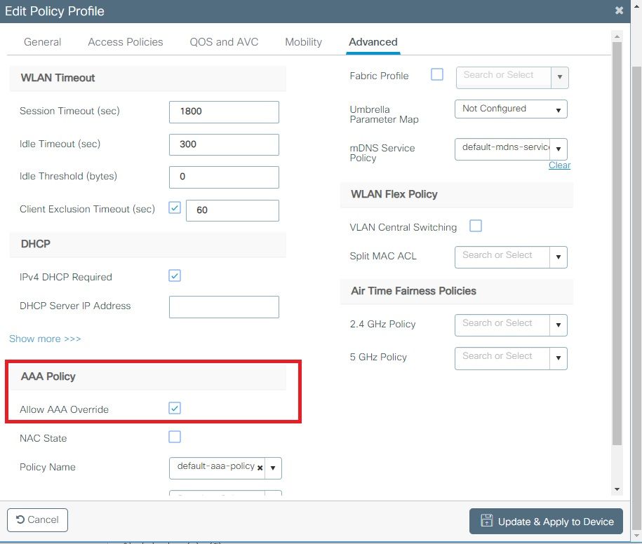
If you plan to have ISE return attributes in the Access-Accept like VLAN Assignment, please enable AAA override in the Advanced tab:
CLI:
# config
# wireless profile policy <policy-profile-name>
# aaa-override
# central switching
# description "<description>"
# vlan <vlanID-or-VLAN_name>
# no shutdown
Policy Tag Configuration
Policy Tag is used to link the SSID with the Policy Profile. You can either create a new Policy Tag or use the default-policy tag.
Note: The default-policy-tag automatically maps any SSID with a WLAN ID between 1 and 16 to the default-policy-profile. It cannot be modified nor deleted. If you have a WLAN with ID 17 or higher, the default-policy-tag cannot be used.
GUI:
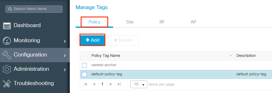
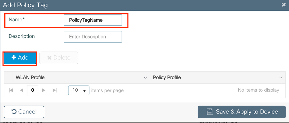
Navigate to Configugation > Tags & Profiles > Tags > Policy and add a new one if needed.
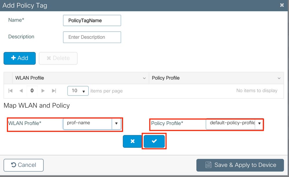
Link your WLAN Profile to the desired Policy Profile.
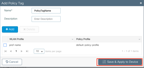
CLI:
# config t
# wireless tag policy <policy-tag-name>
# wlan <profile-name> policy <policy-profile-name>
Policy Tag Assignation
Assign the Policy Tag to the needed APs.
GUI:
To assign the tag to one AP, navigate to Configuration > Wireless > Access Points > AP Name > General Tags, assign the relevant policy tag and then click Update & Apply to Device.
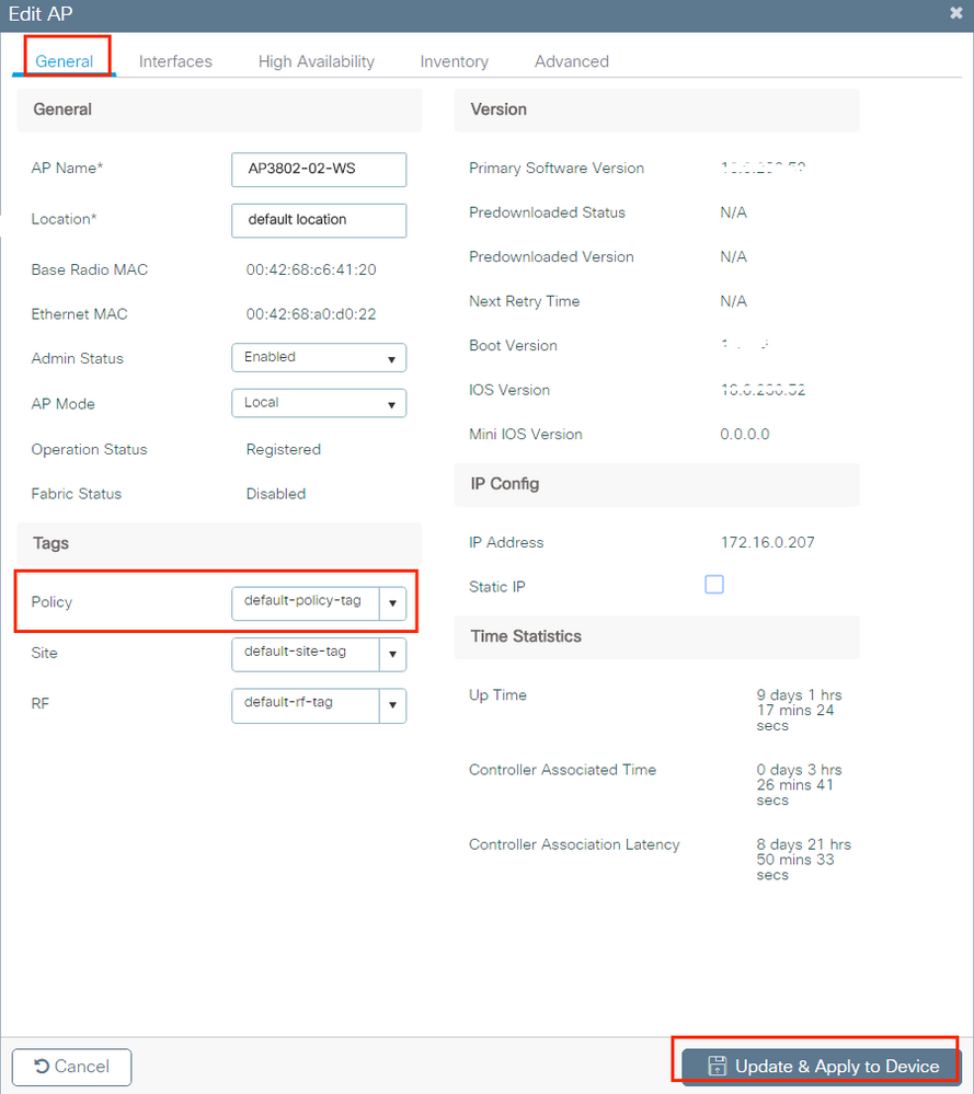
Note: Be aware that when the policy tag on an AP is changed, it drops its association to the 9800 WLC and joins back a few moments later.
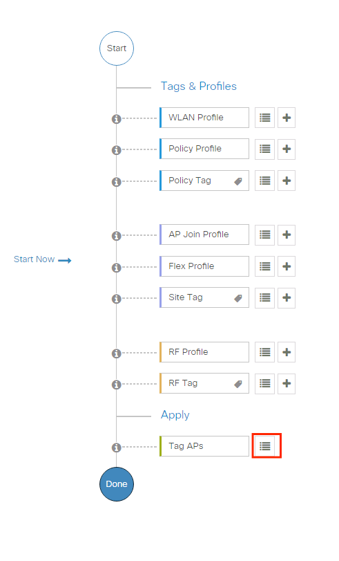
To assign the same Policy Tag to several APs, navigate to Configuration > Wireless Setup > Advanced > Start Now > Apply.
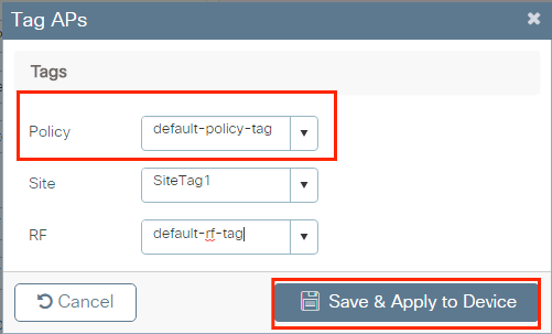
Select the APs to which you want to assign the tag and click + Tag APs
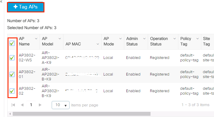
Select the applicable Tags for Policy, Site, and RF and click Save & Apply to Device
CLI:
# config t
# ap <ethernet-mac-addr>
# policy-tag <policy-tag-name>
# end
ISE Configuration
Declare the WLC on ISE
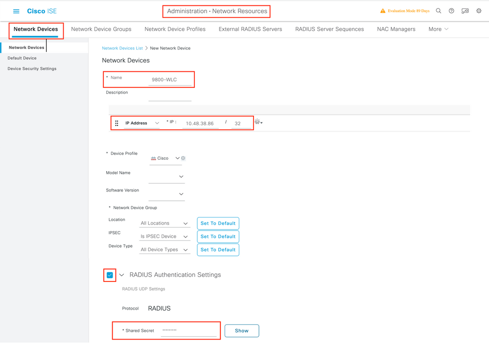
Step 1. Open the ISE console and navigate to Administration > Network Resources > Network Devices > Add as shown in the image.

Step 2. Configure the network device.
Optionally, it can be a specified Model name, software version, description, and assign Network Device groups based on device types, location, or WLCs.
The IP address here corresponds to the WLC interface that sends the authentication requests. By default it is the management interface as shown in the image:
For more information about Network Device Groups review the chapter: Manage Network Devices from the Cisco Identity Services Engine Administrator Guide, : Network Device Groups
Create New User on ISE
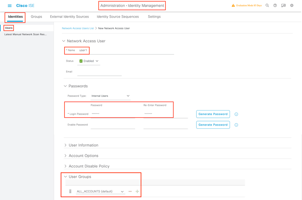
Step 1. Navigate to Administration > Identity Management > Identities > Users > Add as shown in the image:

Step 2. Enter the information for the user. In this example, this user belongs to a group called ALL_ACCOUNTS but it can be adjusted as needed as shown in the image:
Create Authorization Profile
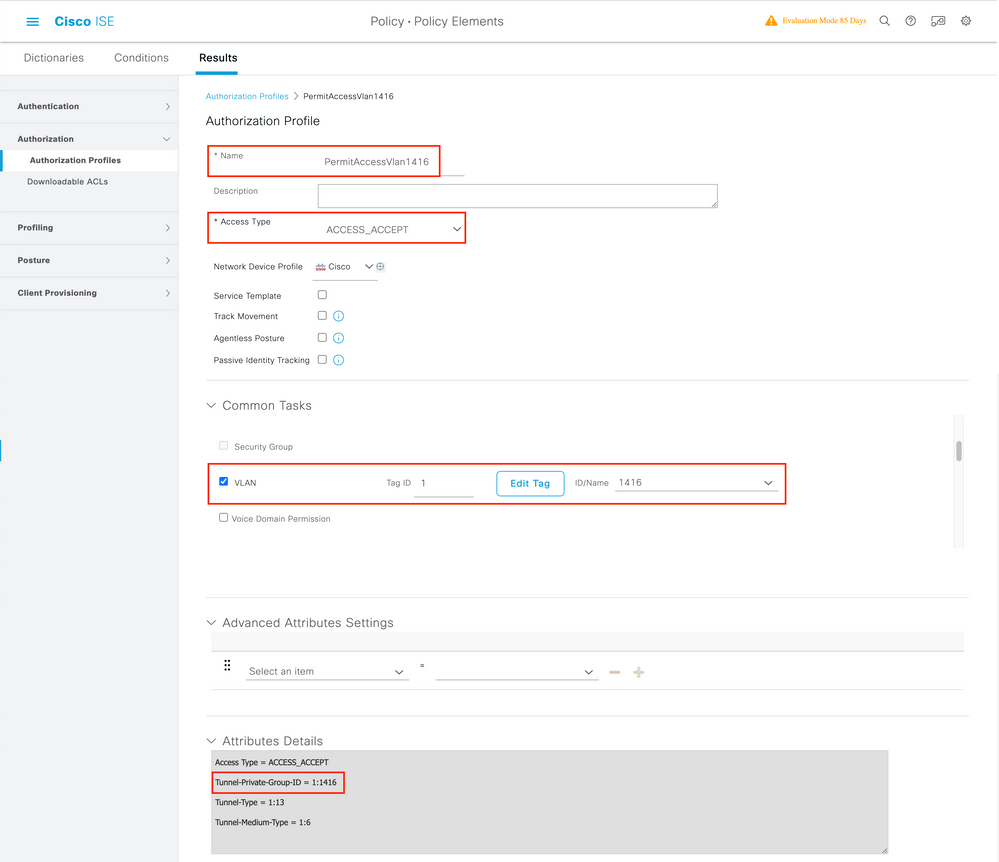
The Authorization Profile consists of a set of attributes that are returned when a condition is matched. The authorization profile determines if the client has access or not to the network, push Access Control Lists (ACLs), VLAN override or any other parameter. The authorization profile shown in this example sends an access accept for the client and assigns the client to VLAN 1416.
Step 1. Navigate to Policy > Policy Elements > Results > Authorization > Authorization Profiles and click the Add button.

Step 2. Enter the values as shown in the image. Here we can return AAA override attributes like VLAN as example. WLC 9800 accepts tunnel attributes 64, 65, 81 that uses VLAN id or Name, and accepts also the use of the AirSpace-Interface-Name attribute.
Create a Policy Set
A Policy Set defines a collection of Authentication and Authorization rules. To create one, go to Policy > Policy Sets, click on the gear of the first Policy Set in the list and select Insert new row above as shown in this image:

Configure a name and create a condition for this Policy Set. In this example, the condition specifies that we match the traffic that comes from the WLC:
Radius:NAS-IP-Address EQUALS X.X.X.X // X.X.X.X is the WLC IP address
Make sure Default Network Access is selected under Allowed Protocols / Server Sequence.

Create Authentication Policy
To configure Authentication and Authorization policies, you need to enter the Policy Set configuration. This can be done if you click the blue arrow at the right of the Policy Set line:

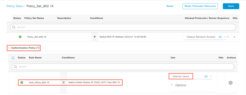
Authentication policies are used to verify if the credentials of the users are correct (verify if the user really is who it says it is). Under Authenticaton Policy, create an Authentication Policy and configure it as shown in this image. The condition for the policy used in this example is:
RADIUS:Called-Station-ID ENDS_WITH <SSID> // <SSID> is the SSID of your WLAN
Also, choose theInternal Users under the Use tab of this Authentication Policy.
Create Authorization Policy
On the same page, go to Authorization Policy and create a new one. The condition for this Authorization Policy is:
RADIUS:Called-Station-ID ENDS_WITH <SSID> // <SSID> is the SSID of your WLAN
Under the Result > Profiles tab of this policy, select the Authorization Profile you created earlier. This causes ISE to send the correct attributes to the WLC if the user is authenticated.

At this point, all the configuration for the WLC and ISE is complete, you can now try to connect with a client.
For more information about ISE Allow Protocols Policies check the chapter: Manage Authentication Policies from the Cisco Identity Services Engine Administrator Guide Manage Authentication Policies
For more information about ISE Identity Sources check the chapter: Manage Users and External Identity Sources from the Cisco Identity Services Engine Administrator Guide: Identity Sources
Verify
You can use these commands to verify your current configuration:
# show run wlan // WLAN configuration
# show run aaa // AAA configuration (server, server group, methods)
# show aaa servers // Configured AAA servers
# show ap config general // AP's configurations
# show ap name <ap-name> config general // Detailed configuration of specific AP
# show ap tag summary // Tag information for AP'S
# show wlan { summary | id | name | all } // WLAN details
# show wireless tag policy detailed <policy-tag name> // Detailed information on given policy tag
# show wireless profile policy detailed <policy-profile name>// Detailed information on given policy profile
Troubleshoot

Note: The usage of external load balancers is fine. However, make sure your load balancer works on a per-client basis by using the calling-station-id RADIUS attribute. Relying on UDP source port is not a supported mechanism for balancing RADIUS requests from the 9800.
Troubleshoot on the WLC
WLC 9800 provides ALWAYS-ON trace capabilities. This ensures all client connectivity-related errors, warnings, and notice level messages are constantly logged and you can view logs for an incident or failure condition after it has occurred.
It depends on the volume of logs generated but usually, you can go back a few hours to several days.
In order to view the traces that 9800 WLC collected by default, you can connect by SSH/Telnet to the 9800 WLC and perform these steps: (Ensure you log the session to a text file).
Step 1. Check the WLC current time so you can track the logs in the time back to when the issue occurred.
# show clock
Step 2. Collect syslogs from the WLC buffer or the external syslog, as dictated by the system configuration. This provides a quick view into the system health and errors, if any.
# show logging
Step 3. Verify if any debug conditions are enabled.
# show debugging
IOSXE Conditional Debug Configs:

Conditional Debug Global State: Stop

IOSXE Packet Tracing Configs:


Packet Infra debugs:

Ip Address                                               Port
------------------------------------------------------|----------
Note: If you see any condition listed, it means the traces are logged up to debug level for all the processes that encounter the enabled conditions (mac address, ip address, and so on). This increases the volume of logs. Therefore, it is recommended to clear all conditions when not actively debugging.
Step 4. Assume the mac address under test was not listed as a condition in Step 3, collect the always-on notice level traces for the specific mac address:
# show logging profile wireless filter { mac | ip } { <aaaa.bbbb.cccc> | <a.b.c.d> } to-file always-on-<FILENAME.txt>
You can either display the content on the session or you can copy the file to an external TFTP server:
# more bootflash:always-on-<FILENAME.txt>
or
# copy bootflash:always-on-<FILENAME.txt> tftp://a.b.c.d/path/always-on-<FILENAME.txt>
Conditional Debugging and Radio Active Tracing
If the always-on traces do not give you enough information to determine the trigger for the problem under investigation, you can enable conditional debugging and capture Radio Active (RA) trace, which provides debug-level traces for all processes that interact with the specified condition (client mac address in this case). You can do this through the GUI or the CLI.
CLI:
In order to enable conditional debugging, perform these steps:
Step 5. Ensure there are no debug conditions enabled.
# clear platform condition all
Step 6. Enable the debug condition for the wireless client mac address that you want to monitor.
This command starts to monitor the provided mac address for 30 minutes (1800 seconds). You can optionally increase this time up to 2085978494 seconds.
# debug wireless mac <aaaa.bbbb.cccc> {monitor-time <seconds>}
Note: In order to monitor more than one client at a time, run debug wireless mac <aaaa.bbbb.cccc> command per mac address.
Note: You do not see the output of the client activity on a terminal session, as everything is buffered internally to be viewed later.
Step 7. Reproduce the issue or behavior that you want to monitor.
Step 8. Stop the debugs if the issue is reproduced before the default or configured monitor time elapses.
# no debug wireless mac <aaaa.bbbb.cccc>
Once the monitor-time has elapsed or the debug wireless has been stopped, the 9800 WLC generates a local file with the name:
ra_trace_MAC_aaaabbbbcccc_HHMMSS.XXX_timezone_DayWeek_Month_Day_year.log
Step 9. Collect the file of the mac address activity. You can either copy the ra trace.log to an external server or display the output directly on the screen.
Check the name of the RA traces file:
# dir bootflash: | inc ra_trace
Copy the file to an external server:
# copy bootflash:ra_trace_MAC_aaaabbbbcccc_HHMMSS.XXX_timezone_DayWeek_Month_Day_year.log tftp://a.b.c.d/ra-FILENAME.txt
Display the content:
# more bootflash:ra_trace_MAC_aaaabbbbcccc_HHMMSS.XXX_timezone_DayWeek_Month_Day_year.log
Step 10. If the root cause is still not obvious, collect the internal logs, which are a more verbose view of debug level logs. You do not need to debug the client again as we look further in detail at debug logs that have been already collected and internally stored.
# show logging profile wireless internal filter { mac | ip } { <aaaa.bbbb.cccc> | <a.b.c.d> } to-file ra-internal-<FILENAME>.txt
Note: This command output returns traces for all log levels for all processes and is quite voluminous. Please engage Cisco TAC to help parse through these traces.
You can either copy the ra-internal-FILENAME.txt to an external server or display the output directly on the screen.
Copy the file to an external server:
# copy bootflash:ra-internal-<FILENAME>.txt tftp://a.b.c.d/ra-internal-<FILENAME>.txt
Display the content:
# more bootflash:ra-internal-<FILENAME>.txt
Step 11. Remove the debug conditions.
# clear platform condition all
Note: Ensure you always remove the debug conditions after a troubleshoot session.
GUI:
Step 1. Go to Troubleshooting > Radioactive Trace > + Add and specify the MAC/IP address of the client(s) you want to troubleshoot.

Step 2. Click Start.
Step 3. Reproduce the issue.
Step 4. Click Stop.
Step 5. Click the Generate button, select the time interval you want to get the logs for, and click Apply to Device. In this example, the logs for the last 10 minutes are requested.
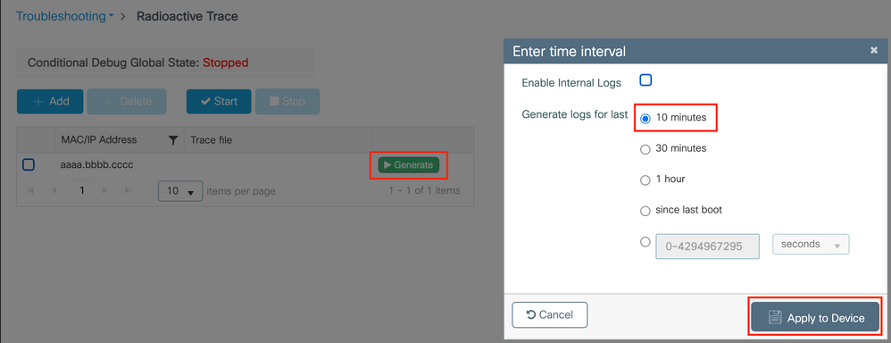
Step 6. Download the Radioactive Trace on your computer and click the download button and inspect it.

Troubleshoot on ISE
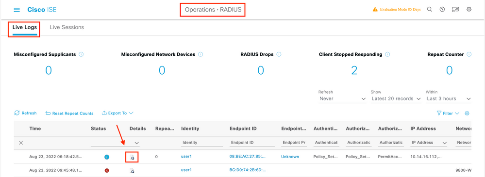
If you experience issues with client authentication, you can verify the logs on the ISE server. Go to Operations > RADIUS > Live Logs and you see the list of authentication requests, as well as the Policy Set that was matched, the result for each request, and so on. You can get more details if you click the magnifying glass under the Details tab of each line, as shown in the image:


 Feedback