Building a Nexus 9000 VXLAN Multisite TRM using DCNM
Available Languages
Download Options
Bias-Free Language
The documentation set for this product strives to use bias-free language. For the purposes of this documentation set, bias-free is defined as language that does not imply discrimination based on age, disability, gender, racial identity, ethnic identity, sexual orientation, socioeconomic status, and intersectionality. Exceptions may be present in the documentation due to language that is hardcoded in the user interfaces of the product software, language used based on RFP documentation, or language that is used by a referenced third-party product. Learn more about how Cisco is using Inclusive Language.
Contents
Introduction
This document is to explain how to deploy a Cisco Nexus 9000 VXLAN Multisite TRM Fabric where Border Gateways are connected via DCI Switches
Topology
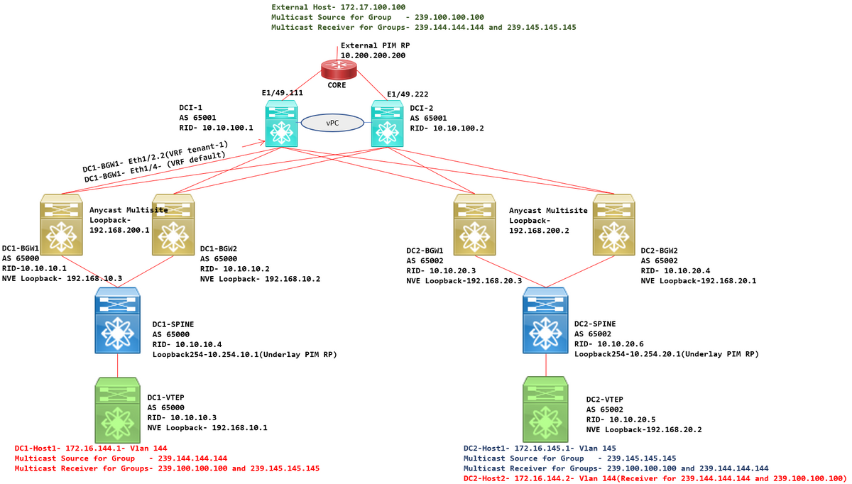
Details of the Topology
- DC1 and DC2 are two Datacenter Locations which are running VXLAN.
- DC1 and DC2 Border Gateways are connected to each other via DCI Switches.
- DCI switches do not run any VXLAN; Those are running eBGP for the underlay for reachability from DC1 to DC2 and Vice Versa. Also the DCI Switches are configured with the tenant vrf; In this example, it would be vrf- "tenant-1".
- DCI switches also connect to External Networks which are non-VXLAN.
- VRFLITE connections are terminated on Border Gateways(Support of Co-existence of VRFLITE and Border Gateway functions started from NXOS-9.3(3) and DCNM-11.3(1))
- Border Gateways are running in Anycast Mode; When running TRM(Tenant Routed Multicast) on this version, Border Gateways cannot be configured as vPC(refer Multisite TRM Configuration guide for other limitations)
- For this topology, All BGW switches will have Two Physical Connections towards each of the DCI switches; One link will be in default VRF(which will be used for the Inter-site Traffic) and other link will be in VRF tenant-1 which is used to extend VRFLITE out to the non-vxlan environment.
PIM/Multicast Details(TRM Specific)
- Underlay PIM RP for both sites are the Spine switches and Loopback254 is configured for the same. Underlay PIM RP is used so that the VTEPs can send PIM Registers as well as PIM Joins to the Spines(for the Purposes of BUM traffic replication for various VNIDs)
- For TRM, RP can be specified by different means; Here for the purpose of the document, PIM RP is the core Router at the top of the topology which is external to the VXLAN Fabric.
- All VTEPs will have the Core router pointed as PIM RP configured in respective VRFs
- DC1-Host1 is sending multicast to the group- 239.144.144.144; DC2-Host1 is receiver for this group in DC2 and a Host External(172.17.100.100) to the vxlan is also subscribing to this group
- DC2-Host1 is sending multicast to the group- 239.145.145.145; DC1-Host1 is receiver for this group in DC1 and a Host External(172.17.100.100) to the vxlan is also subscribing to this group
- DC2-Host2 is in Vlan 144 and is receiver for Multicast groups- 239.144.144.144 and 239.100.100.100
- External Host(172.17.100.100) is sending traffic for which both DC1-Host1 and DC2-Host1 are receivers.
- This covers East/West Inter and Intra Vlan and North/South Multicast Traffic Flows
Components Used
- Nexus 9k switches running 9.3(3)
- DCNM Running 11.3(1)
The information in this document was created from the devices in a specific lab environment. All of the devices used in this document started with a cleared (default) configuration. If your network is live, make sure that you understand the potential impact of any command.
High Level Steps
1) Considering this Document is based on Two DCs utilizing VXLAN Multisite feature, Two Easy Fabrics have to be created
2) Create MSD and move DC1 and DC2
3) Create External Fabric and add DCI switches
4) Create Multisite Underlay and Overlay
5) Create VRF Extension attachments on Border Gateways
6) Verification of Unicast Traffic
7) Verification of Multicast Traffic
Step 1: Creation of Easy Fabric for DC1
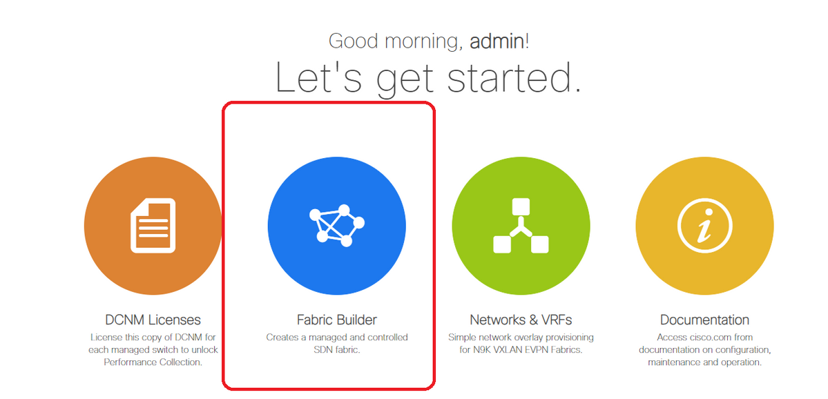
- Login to DCNM and from the Dashboard, Select the option-> "Fabric Builder"
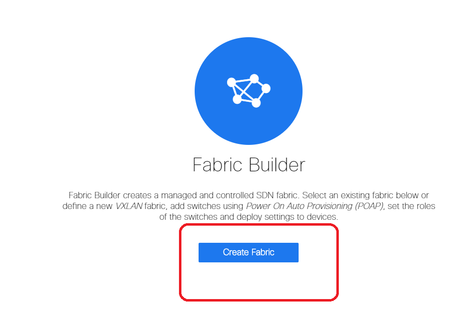
- Select the "Create Fabric" option
- Next is to provide the Fabric Name, Template and then under "General" Tab, Fill up the relevant ASN, fabric interface numbering, Any Cast Gateway MAC(AGM)
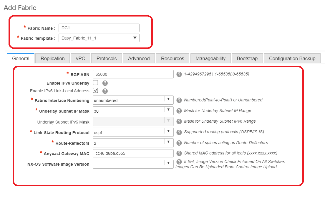
# AGM is used by Hosts in the fabric as the Default Gateway MAC address. This will be the same on all leaf switches(as all Leaf switches within the fabric are running anycast Fabric Forwarding). Default Gateway IP address and MAC address are going to be the same on all Leaf switches
- Next is to set the Replication mode
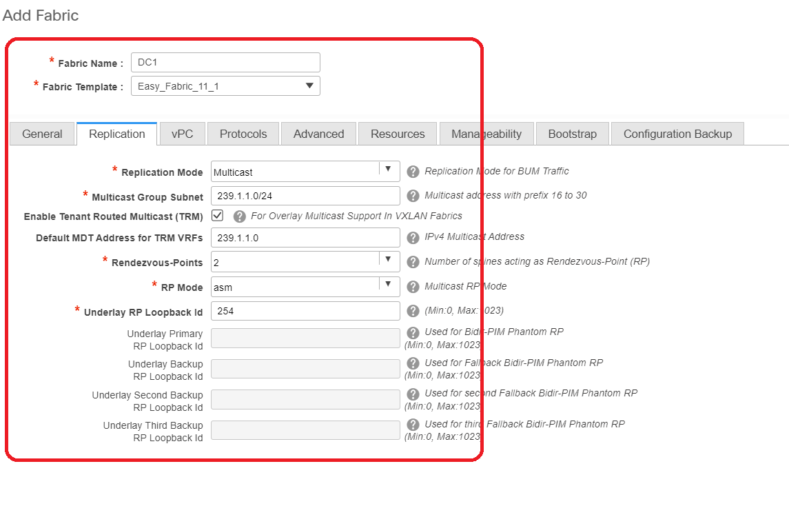
# Replication mode for this documet purpose is Multicast; Another option is to use the Ingress Replication(IR)
# Multicast group subnet will be the multicast group used by VTEPs to replicate BUM Traffic(Like ARP requests)
# Check box for "Enable Tenant Routed Multicast(TRM)" has to be enabled
# Populate other boxes as required.
- Tab for vPC is left untouched as the topology here is not using any vPC
- Next is to the Protocols tab
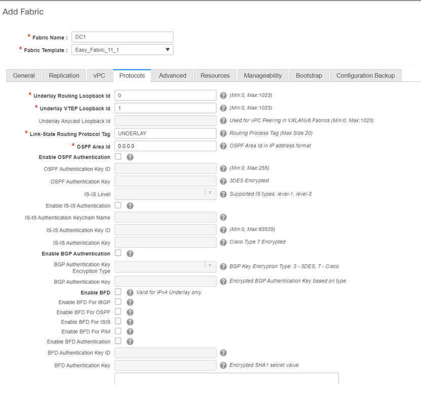
# Modify the relevant boxes as needed.
- Next is Advanced tab
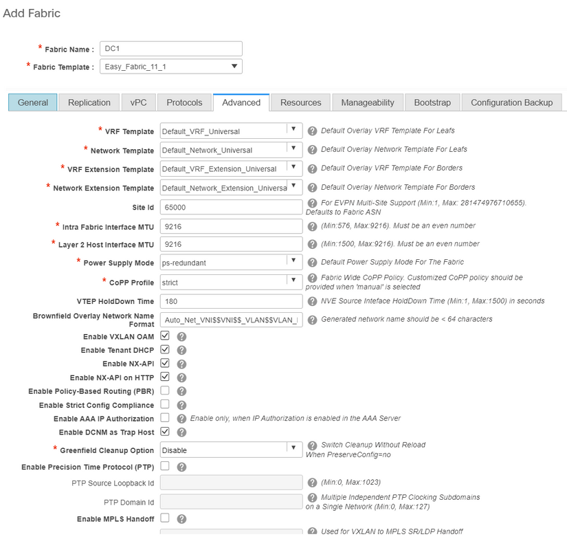
# For this document purpose, all fields are left at default.
# ASN is auto populated from the one that was provided within General tab
- Next is to fill up the fields in "Resources" tab
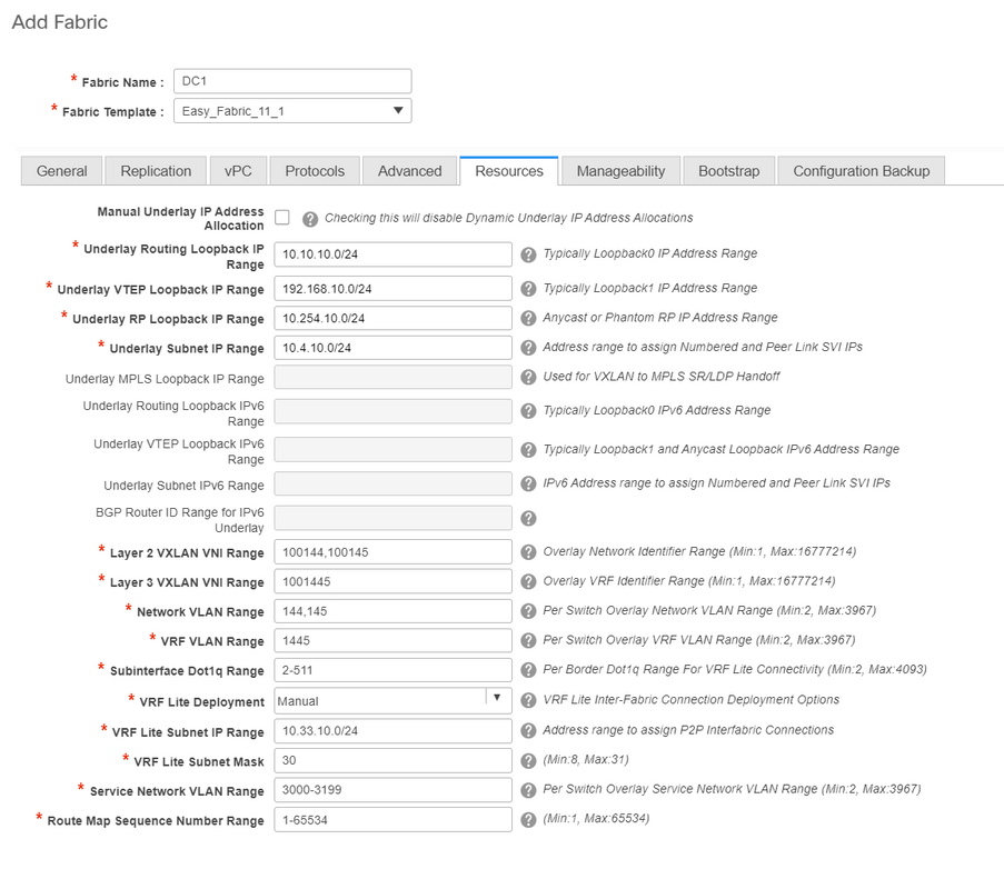
# Underlay Routing Loopback IP range would be the ones used for protocols like BGP, OSPF
# Underlay VTEP loopback IP range are the ones that will be used for the NVE interface.
# Underlay RP is for the PIM RP that is used for BUM multicast groups.
- Fill up other tabs with the relevant information and then "save"
Step 2: Creation of Easy Fabric for DC2
- Perform the same Task as in Step 1 to create an Easy Fabric for DC2
- Make Sure to provide different IP address block Under Resources for NVE and Routing Loopbacks and any other relevant areas
- ASNs should be different as well
- Layer 2 and Layer 2 VNIDs are same
Step 3: Creation of MSD For Multisite
- An MSD fabric will have to be created as shown below.
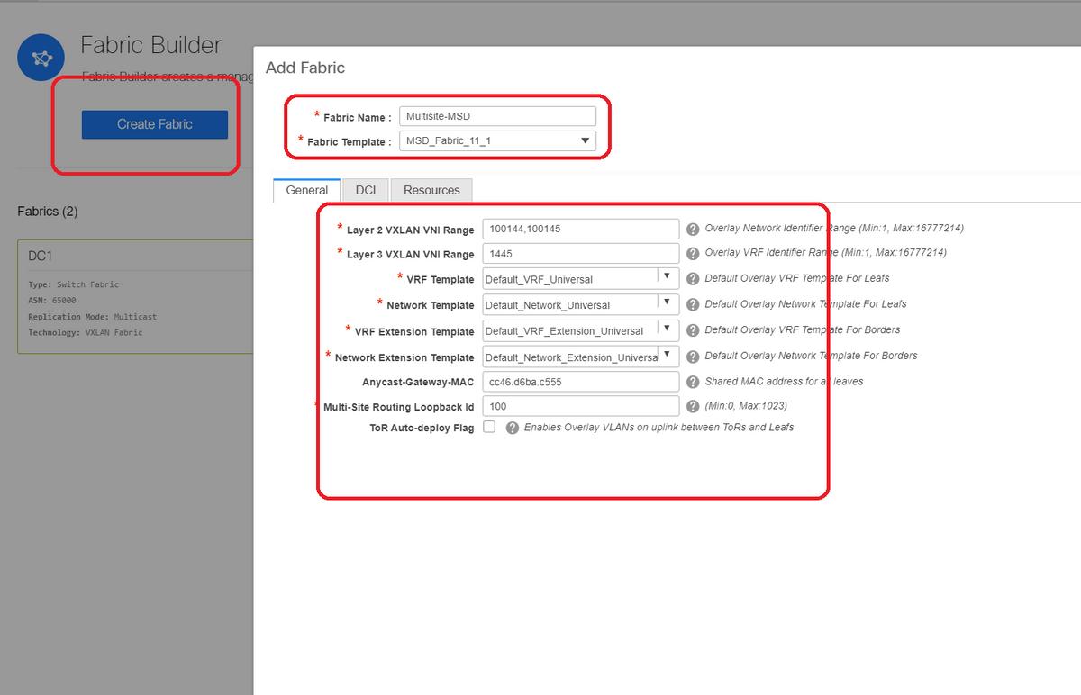
- Fill up the DCI tab as well
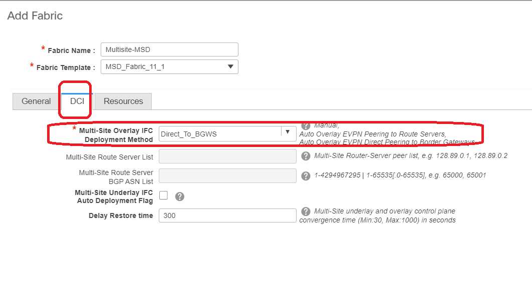
# Multi-site Overlay IFC Deployment method is "Direct_To_BGWS" as here DC1-BGWs will form the Overlay connection with the DC2-BGWs. DCI switches shown in the topology are just transit layer 3 Devices(as well as VRFLITE)
- Next step is to mention the Multisite Loopback Range(This IP address will be used as the Multisite Loopback IP on DC1 and DC2 BGWs; DC1-BGW1 and DC1-BGW2 share the same multisite Loopback IP; DC2-BGW1 and DC2-BGW2 share the same Multisite loopback IP but will be different from that of the DC1-BGWs
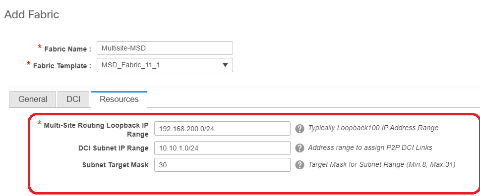
# Once the fields are populated, Click the "save".
# Once steps 1 through 3 are done, the Fabric builder page will look like below.

Step 4: Moving DC1 and DC2 Fabrics into Multisite MSD
# In this step, the DC1 and DC2 fabrics are moved to Multisite-MSD which was created in Step 3. Below are the screenshots on how to achieve the same.
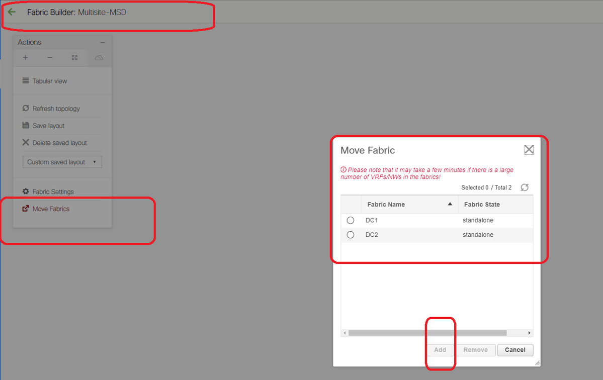
# Select the MSD, click on "move Fabrics" and then select DC1 and DC2 one by one and then "add".
# Once both the fabrics are moved, the home page would look like below

# Multisite-MSD will show DC1 and DC2 as member fabrics
Step 5: Creation of VRFs
# Creating VRFs can be done from MSD fabric which will be applicable for both the Fabrics. Below are the screenshots to achieve the same.

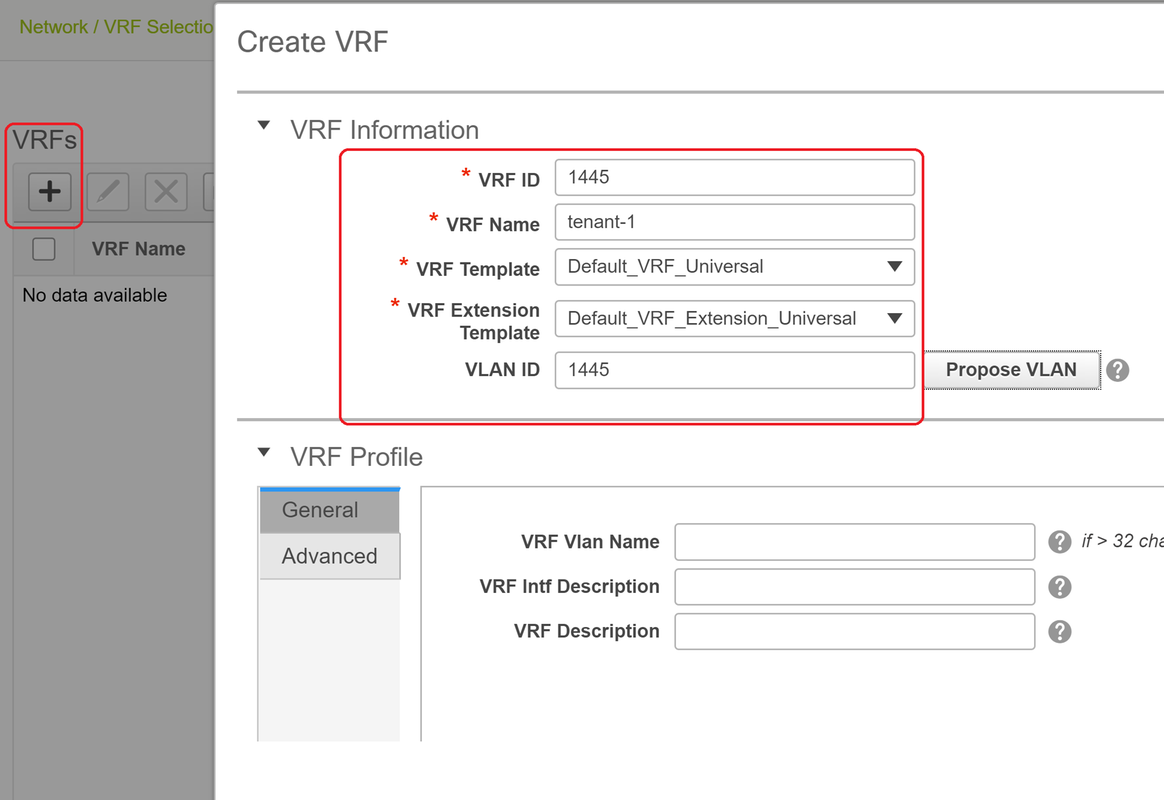
# Fill in the advanced tab as well and then "create"
Step 6: Creation of Networks
# Creating Vlans and corresponding VNIDs, SVIs can be done from MSD fabric which will be applicable for both Fabrics.

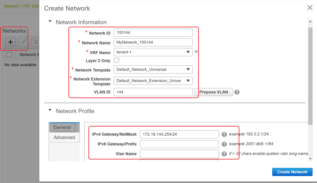
# In "advanced" tab, enable the checkbox if the BGWs are required to be the Gateway for the Networks
# Once all the fields are populated, Click "Create Network"
# Repeat the same steps for any other Vlans/Networks
Step 7: Creation of External Fabric for the DCI Switches
# This example takes into consideration of DCI switches which are in the path of the packet from DC1 to DC2(as far as inter-site communication is concerned) which is commonly seen when there are more than 2 fabrics.
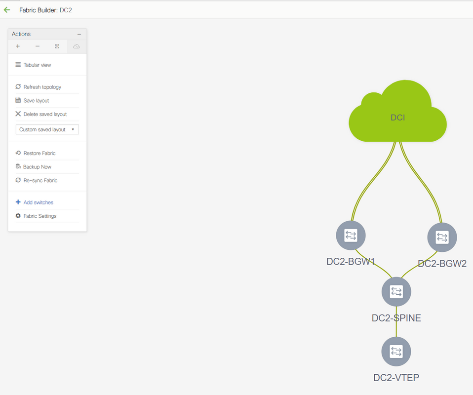
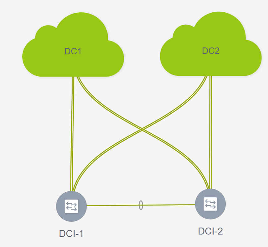
# External Fabric will include the Two DCI Switches that are at the top of the Topology shown in the beginning of this document
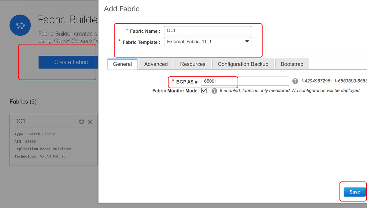
# Create the Fabri with the "external" template and specify the ASN
# Modify any other relevant fields for the deployment
Step 8: Adding switches into each Fabric
# Here, all the switches per fabric will be added into the respective Fabric.
Procedure to add switches is shown in below screenshots.
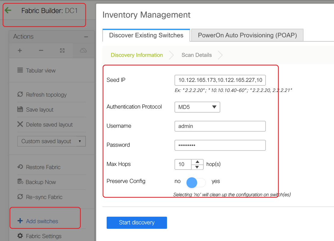
# If "Preseve Config" is "NO"; any switch configuration that is present will be erased; Exception is the hostname, Boot variable, MGMT0 IP address, Route in VRF Context Management
# Set the Roles on switches correctly(by Right click on switch, Set role and then relevant role
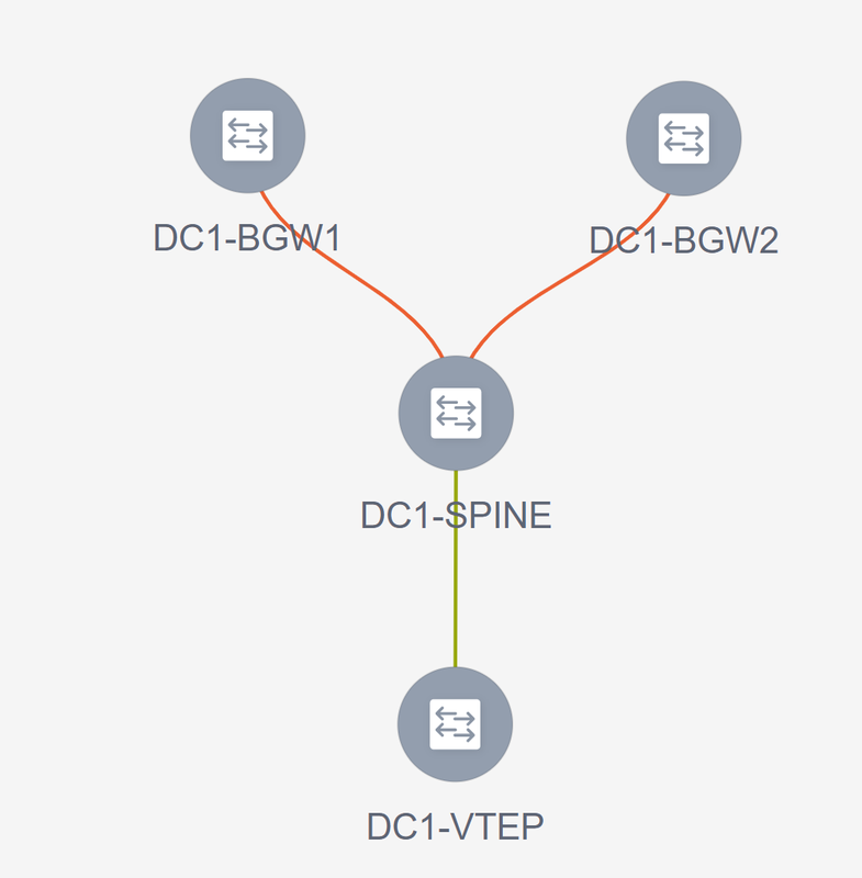
# Also arrange the layout of switches accordingly and then click "save layout"
Step 9: TRM settings for Individual Fabrics
- Next step is to enable TRM checkboxes on each Fabrics
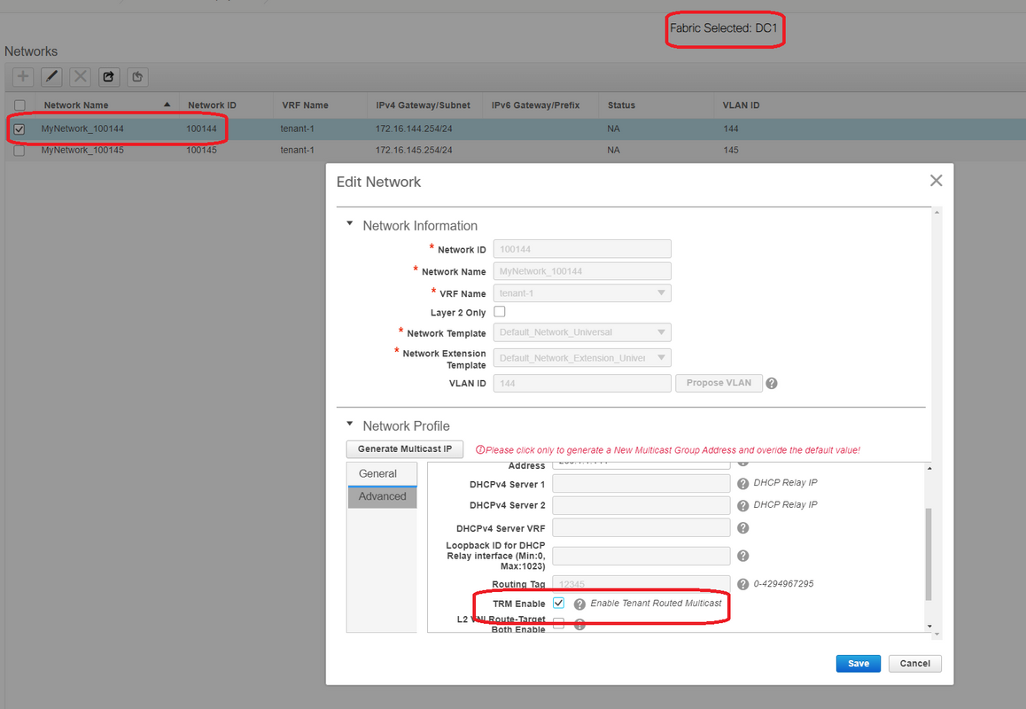
# Perform this step for all Networks for all Fabrics.
- Once this is done, VRFs in individual fabrics are also required to make some changes and add information as below.
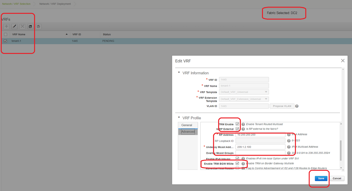
# This has to be done in DC1 and DC2 as well for the VRF section.
# Note that the multicast group for the VRF-> 239.1.2.100 was changed manually from the auto populated one; Best practice is to use different group for the Layer 3 VNI VRF and for any L2 VNI Vlans' BUM traffic multicast group
Step 10: VRFLITE Configuration on Border Gateways
# Starting from NXOS 9.3(3) and DCNM 11.3(1), Border Gateways can act as Border Gateways and VRFLITE connectivity point(which will let the Border Gateway have a VRFLITE neighborship with an external router and so external devices can communicate with the devices in the fabric)
# For the purpose of this document, border Gateways are forming VRFLITE neighborship with the DCI router which are at the north of the topology shown above.
# One point to note is that; VRFLITE and Multisite Underlay Links cannot be the same physical Links. Separate links will have to be spun up to form the vrflite and multisite Underlay
# Screenshots below will illustrate how to achieve both VRF LITE and multisite extensions on Border Gateways.
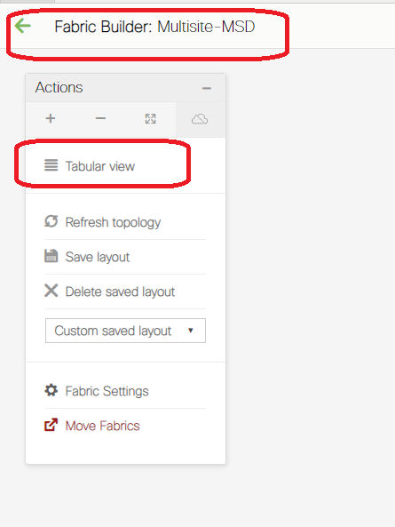
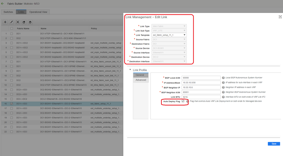
# Switch to "tabular view"
# Move to the tab "links" and then add an "inter-fabric VRFLITE" link and will have to specify the Source Fabric as DC1 and destination Fabric as DCI
# Select the right interface for source interface that leads to the correct DCI Switch
# under link profile, provide the local and remote IP addresses
# Also enable the check box- "auto deploy flag" so that the DCI switches' configuration for VRFLITE will be also auto populated(This is done in a future step)
# ASNs are auto populated
# Once all the fields are filled in with the correct information, Click the "save" button
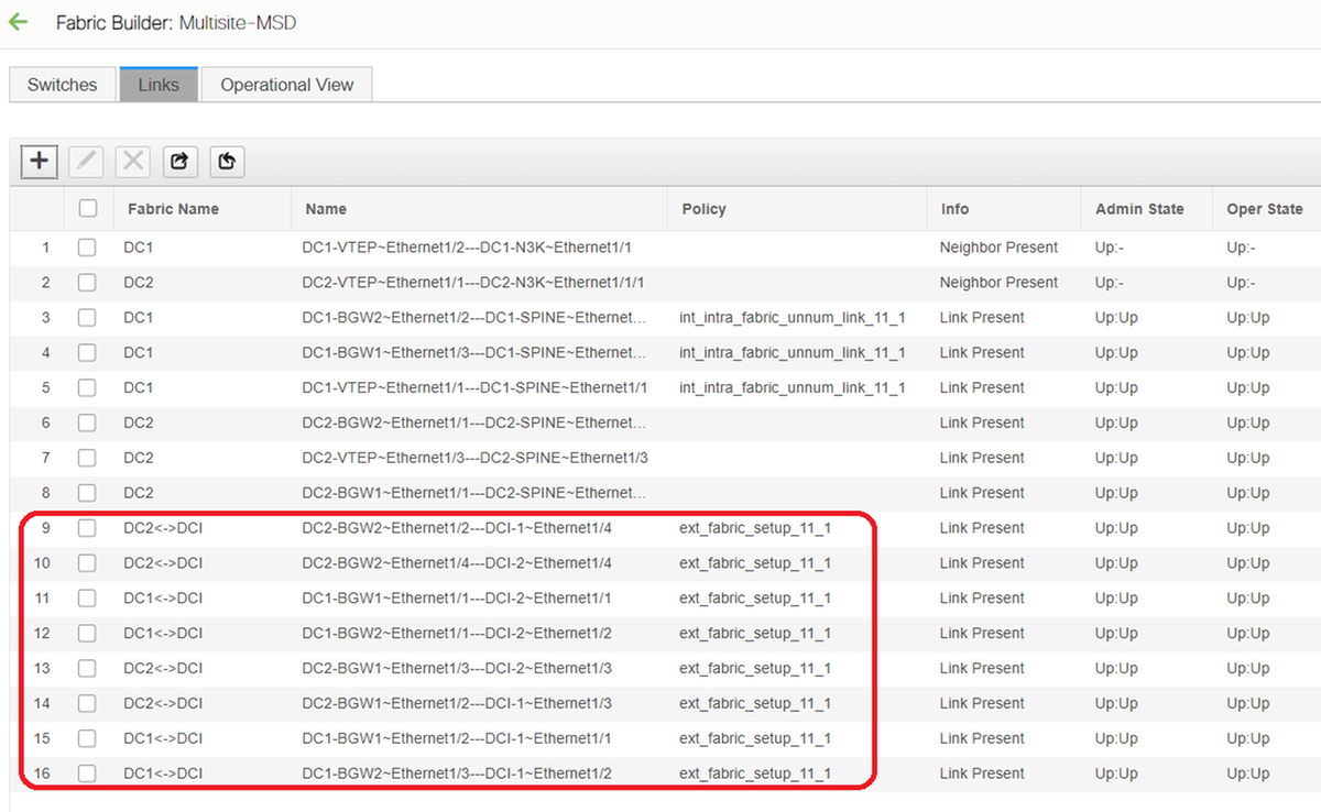
- Above step will have to done for all BGW To DCI Connections on all 4 Border Gateways towards to the Two DCI Switches.
- Considering the topology of this document, there will be a total of 8 inter-fabric VRF LITE connections and it looks like below.
Step 11: Multisite Underlay Configuration on Border Gateways
# Next step is to configure the Multisite Underlay on every Border Gateway in each Fabric.
# For this purpose, we will need separate physical links from BGWs to DCI switches. The links which were used for VRFLITE in step 10 cannot be used for multisite Overlay
# These interfaces will be part of "default vrf" unlike the previous one where the interfaces will be part of tenant vrf(this example, it is tenant-1)
# Below screenshots will help to walk through the steps to do this configuration.
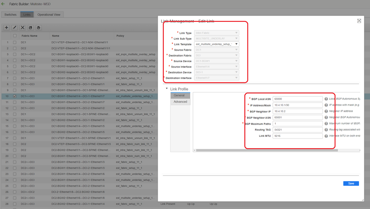
# The same step will have to be performed for all the connections from BGWs to DCI switches
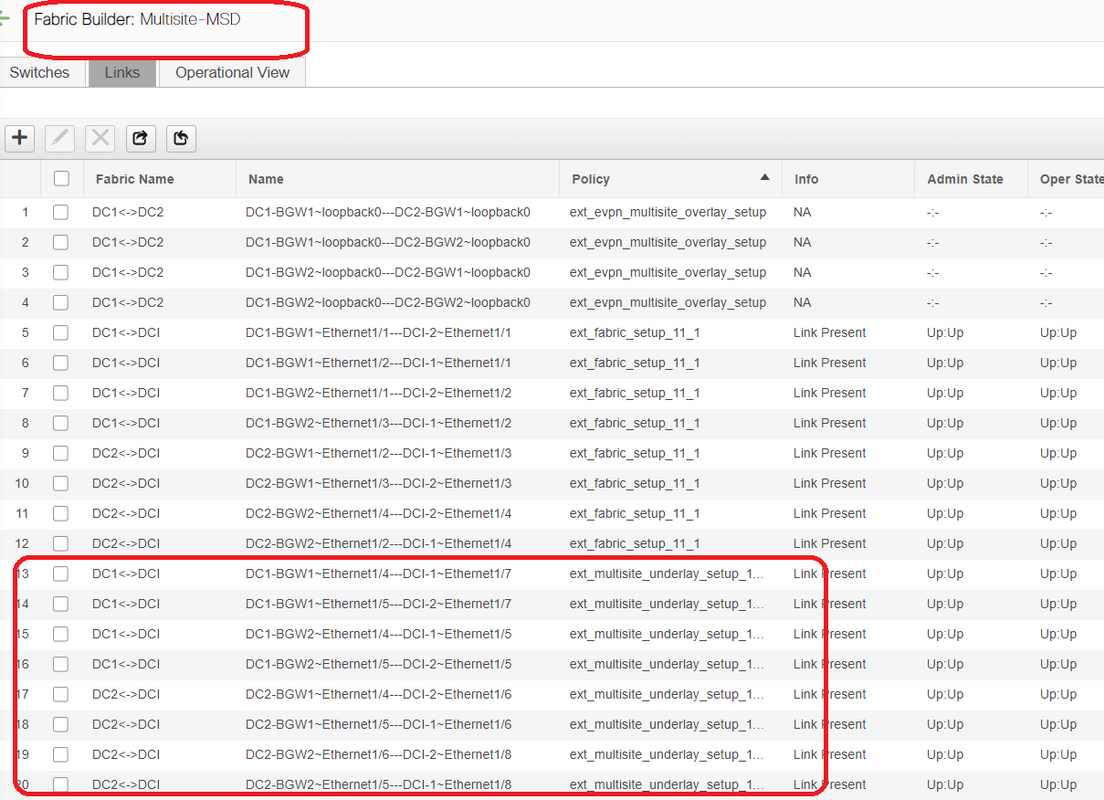
# At the end, a total of 8 inter-fabric multisite underlay connections will be seen as below.
Step 12: Multisite Overlay Settings for TRM
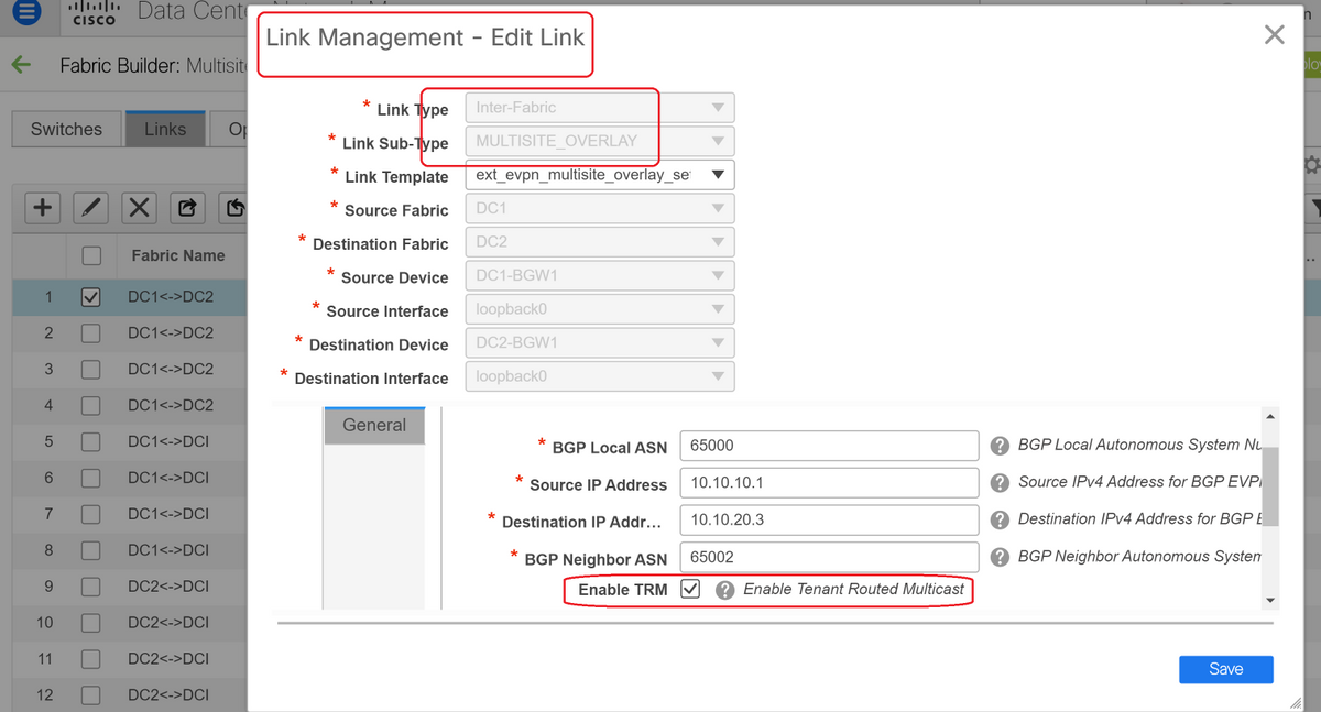
# When Multisite Underlay is completed, the multisite overlay interfaces/Links will be auto-populated and can be seen within the Tabular view under links within Multisite MSD fabric.
# By default, the Multisite Overlay will only form the bgp l2vpn evpn neighborship from Each site BGWs to the other which is required for the unicast communication from one site to another. However, when Multicast is required to run between the sites(which are connected by teh vxlan multisite feature), it is required to enable the TRM checkbox as seen below for all the overlay interfaces within Multisite MSD Fabric. Screenshots will illustrate how to perform this.

Step 13: Save/Deploy in MSD and Individual Fabrics
# Perform a save/deploy which will push relevant configurations as per the above steps that were done
# When Selecting MSD, the configurations which will be pushed, will be only applicable for the Border Gateways.
# Hence it is required to save/deploy for the individual fabrics, which will push the relevant configurations to all the regular Leaf switches/VTEPs
Step 14: VRF Extension attachments for MSD
# Select the MSD and go to the VRF section

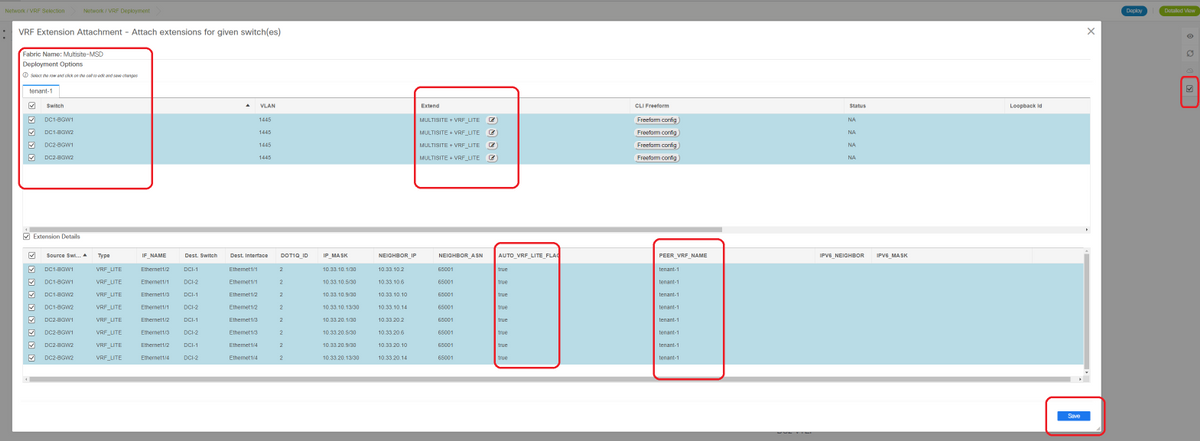
# Note that the Extend option has to be "MULTISITE+VRF_LITE" as in this document, border Gateway functionality and the VRFLITE are integrated onto the Border Gateway switches.
# AUTO_VRF_LITE will be set to true
# PEER VRF NAME will have to be populated manually for all 8 as shown below from BGWs to DCI Switches(here, the example uses the same VRF NAME on DCI Switches)
# Once done, Click "save"
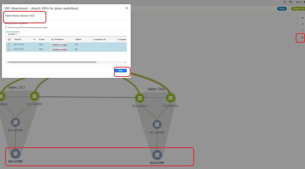
# While creating VRF Extensions, only the Boder Gateways will have extra configurations towards the VRFLITE DCI switches
# Hence the regular leaf will have to be selected separately and then click on the "checkboxes" for each Tenant VRFs as shown above.
# Click on Deploy to push the configurations
Step 15: Pushing Network configurations to the Fabric from MSD

# Select the relevant Networks within MSD fabric
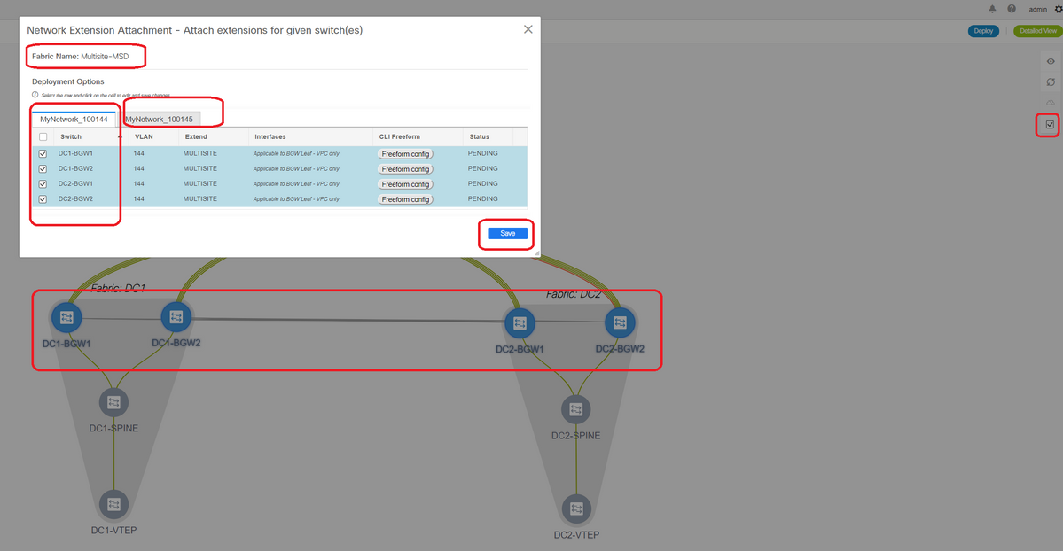
# Note that only the Border Gateways are selected at the moment; Perform the same and select the Regular Leaf switches/VTEPs-> DC1-VTEP and DC2-VTEP in this case.
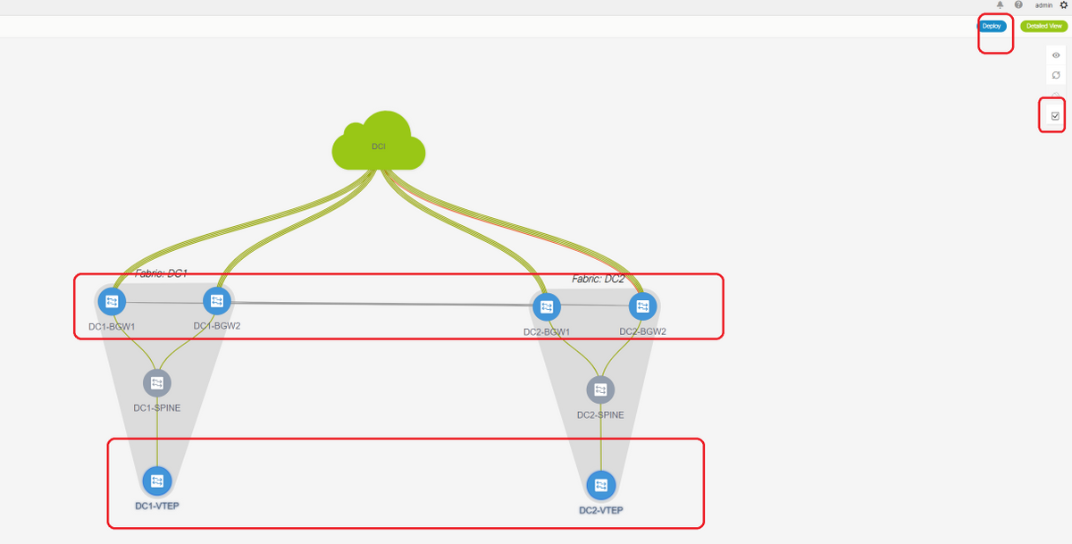
# Once done, click the "deploy"(which will push configurations to all 6 switches above)
Step 16: Verifying VRF and Networks on all VRFs
# This step is to verify if the VRF and Networks are shown as "Deployed" on all Fabrics; if its showing as pending, Make sure to "deploy" the configurations.
Step 17: Deploying configurations on External Fabric
# This step is required so as to push all the relevant IP addressing, BGP, VRFLITE configurations to the DCI Switches.
# To do this, Select the External Fabric and click on "save & Deploy"
DCI-1# sh ip bgp sum
BGP summary information for VRF default, address family IPv4 Unicast
BGP router identifier 10.10.100.1, local AS number 65001
BGP table version is 173, IPv4 Unicast config peers 4, capable peers 4
22 network entries and 28 paths using 6000 bytes of memory
BGP attribute entries [3/504], BGP AS path entries [2/12]
BGP community entries [0/0], BGP clusterlist entries [0/0]

Neighbor        V    AS MsgRcvd MsgSent   TblVer  InQ OutQ Up/Down  State/PfxRcd
10.4.10.1       4 65000      11      10      173    0    0 00:04:42 5
10.4.10.9       4 65000      11      10      173    0    0 00:04:46 5
10.4.20.37      4 65002      11      10      173    0    0 00:04:48 5
10.4.20.49      4 65002      11      10      173    0    0 00:04:44 5
DCI-1# sh ip bgp sum vrf tenant-1
BGP summary information for VRF tenant-1, address family IPv4 Unicast
BGP router identifier 10.33.10.2, local AS number 65001
BGP table version is 14, IPv4 Unicast config peers 4, capable peers 4
2 network entries and 8 paths using 1200 bytes of memory
BGP attribute entries [2/336], BGP AS path entries [2/12]
BGP community entries [0/0], BGP clusterlist entries [0/0]

Neighbor        V    AS MsgRcvd MsgSent   TblVer  InQ OutQ Up/Down  State/PfxRcd
10.33.10.1      4 65000       8      10       14    0    0 00:01:41 2
10.33.10.9      4 65000      10      11       14    0    0 00:03:16 2
10.33.20.1      4 65002      11      10       14    0    0 00:04:40 2
10.33.20.9      4 65002      11      10       14    0    0 00:04:39 2

DCI-2# sh ip bgp sum
BGP summary information for VRF default, address family IPv4 Unicast
BGP router identifier 10.10.100.2, local AS number 65001
BGP table version is 160, IPv4 Unicast config peers 4, capable peers 4
22 network entries and 28 paths using 6000 bytes of memory
BGP attribute entries [3/504], BGP AS path entries [2/12]
BGP community entries [0/0], BGP clusterlist entries [0/0]

Neighbor        V    AS MsgRcvd MsgSent   TblVer  InQ OutQ Up/Down  State/PfxRcd
10.4.10.5       4 65000      12      11      160    0    0 00:05:10 5
10.4.10.13      4 65000      12      11      160    0    0 00:05:11 5
10.4.20.45      4 65002      12      11      160    0    0 00:05:10 5
10.4.20.53      4 65002      12      11      160    0    0 00:05:07 5
DCI-2# sh ip bgp sum vrf tenant-1
BGP summary information for VRF tenant-1, address family IPv4 Unicast
BGP router identifier 10.33.10.6, local AS number 65001
BGP table version is 14, IPv4 Unicast config peers 4, capable peers 4
2 network entries and 8 paths using 1200 bytes of memory
BGP attribute entries [2/336], BGP AS path entries [2/12]
BGP community entries [0/0], BGP clusterlist entries [0/0]

Neighbor        V    AS MsgRcvd MsgSent   TblVer  InQ OutQ Up/Down  State/PfxRcd
10.33.10.5      4 65000      10      11       14    0    0 00:03:28 2
10.33.10.13     4 65000      11      11       14    0    0 00:04:30 2
10.33.20.5      4 65002      12      11       14    0    0 00:05:05 2
10.33.20.13     4 65002      12      11       14    0    0 00:05:03 2
# Once deployed, we will see 4 IPv4 BGP neighborships from Each DCI Switch to all BGWs and 4 IPv4 VRF BGP neighborships as well(which is for the tenant VRF EXtension)
Step 18: Configuring iBGP Between DCI switches
# Considering that DCI switches are having links connected between each other, an iBGP IPv4 neighborship is ideal so that if any downstream connections go down on DCI-1 switch, the North to South traffic can still be forwarded via DCI-2
# For this, an iBGP IPv4 Neighborship is required between DCI switches and use next-hop-self as well on each side.
# A Freeform will have to be spun up on DCI switches to achieve this. The required lines of configurations are as below.
# DCI switches in the above topology are configured in vPC; so, the backup SVI can be used to build the iBGP Neighborships
# Select the DCI fabric and right click each switch and "view/edit policies"
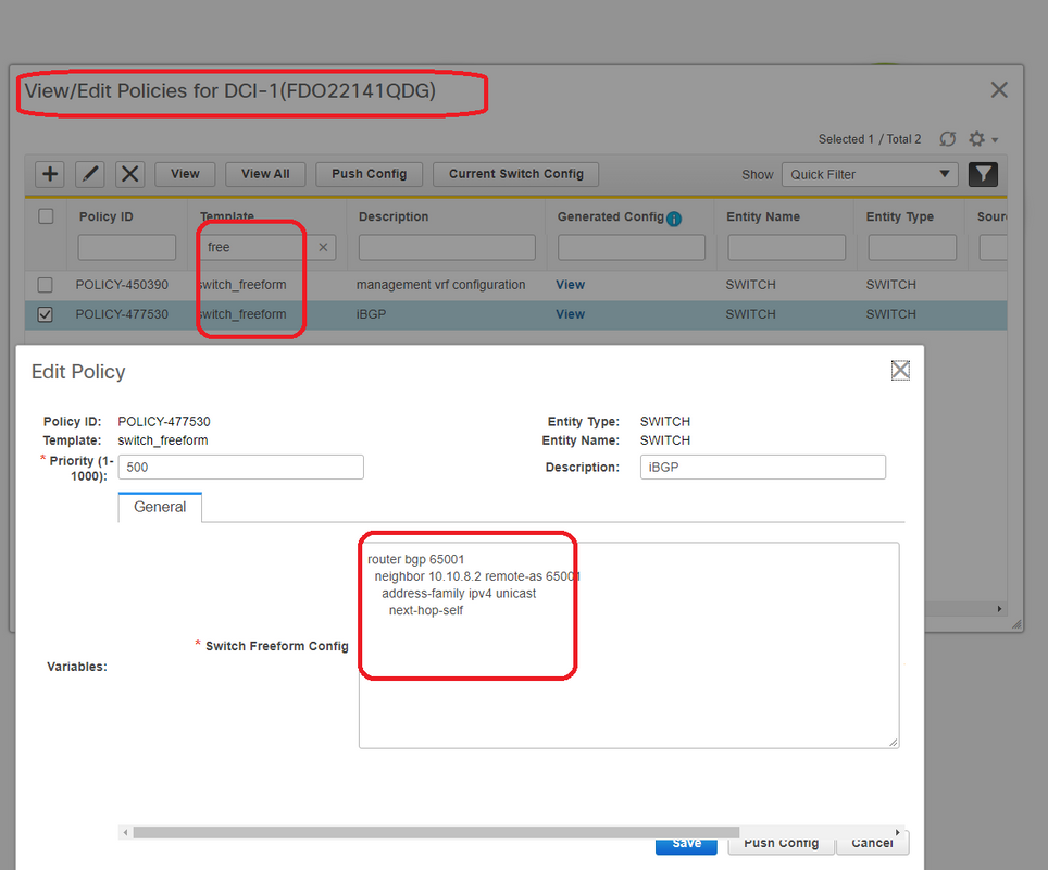
# Do the same change on DCI-2 switch and then "save&Deploy" to push the actual configurations to the DCI switches
# Once done, CLI verification can be done using the below command.
DCI-2# sh ip bgp sum
BGP summary information for VRF default, address family IPv4 Unicast
BGP router identifier 10.10.100.2, local AS number 65001
BGP table version is 187, IPv4 Unicast config peers 5, capable peers 5
24 network entries and 46 paths using 8400 bytes of memory
BGP attribute entries [6/1008], BGP AS path entries [2/12]
BGP community entries [0/0], BGP clusterlist entries [0/0]

Neighbor        V    AS MsgRcvd MsgSent   TblVer  InQ OutQ Up/Down  State/PfxRcd
10.4.10.5       4 65000    1206    1204      187    0    0 19:59:17 5
10.4.10.13      4 65000    1206    1204      187    0    0 19:59:19 5
10.4.20.45      4 65002    1206    1204      187    0    0 19:59:17 5
10.4.20.53      4 65002    1206    1204      187    0    0 19:59:14 5
10.10.8.1       4 65001      12       7      187    0    0 00:00:12 18    # iBGP neighborship from DCI-2 to DCI-1
Step 19: Verification of IGP/BGP neighborships
OSPF neighborships
# As all the Underlay IGP is OSPF in this example, All VTEPs will form OSPF neighborship with the spines and this includes the BGW switches in one site as well.
DC1-SPINE# show ip ospf neighbors
 OSPF Process ID UNDERLAY VRF default
 Total number of neighbors: 3
 Neighbor ID     Pri State            Up Time  Address         Interface
 10.10.10.3        1 FULL/ -          1d01h    10.10.10.3      Eth1/1     # DC1-Spine to DC1-VTEP
 10.10.10.2        1 FULL/ -          1d01h    10.10.10.2      Eth1/2     # DC1-Spine to DC1-BGW2
 10.10.10.1        1 FULL/ -          1d01h    10.10.10.1      Eth1/3     # DC1-Spine to DC1-BGW1
# All loopbacks(BGP Router IDs, NVE loopbacks) are advertised in OSPF; Hence within a fabric, all Loopbacks are learnt via OSPF routing protocol which would help in further forming the l2vpn evpn neighborship
BGP neighborships
# Within a fabric, This topology will have l2vpn evpn neighborships from Spines to the Regular VTEPs and also to Border Gateways.
DC1-SPINE# show  bgp l2vpn evpn sum
BGP summary information for VRF default, address family L2VPN EVPN
BGP router identifier 10.10.10.4, local AS number 65000
BGP table version is 80, L2VPN EVPN config peers 3, capable peers 3
22 network entries and 22 paths using 5280 bytes of memory
BGP attribute entries [14/2352], BGP AS path entries [1/6]
BGP community entries [0/0], BGP clusterlist entries [0/0]

Neighbor        V    AS MsgRcvd MsgSent   TblVer  InQ OutQ Up/Down  State/PfxRcd
10.10.10.1      4 65000    1584    1560       80    0    0    1d01h 10        # DC1-Spine to DC1-BGW1
10.10.10.2      4 65000    1565    1555       80    0    0    1d01h 10        # DC1-Spine to DC1-BGW2
10.10.10.3      4 65000    1550    1554       80    0    0    1d01h 2         # DC1-Spine to DC1-VTEP
# Considering that this is a multisite Deployment with Border Gateways peering from one site to other using eBGP l2vpn evpn, the same can be verified using below command on a Border Gateway switch.
DC1-BGW1# show  bgp l2vpn evpn sum
BGP summary information for VRF default, address family L2VPN EVPN
BGP router identifier 10.10.10.1, local AS number 65000
BGP table version is 156, L2VPN EVPN config peers 3, capable peers 3
45 network entries and 60 paths using 9480 bytes of memory
BGP attribute entries [47/7896], BGP AS path entries [1/6]
BGP community entries [0/0], BGP clusterlist entries [2/8]

Neighbor        V    AS MsgRcvd MsgSent   TblVer  InQ OutQ Up/Down  State/PfxRcd
10.10.10.4      4 65000    1634    1560      156    0    0    1d01h 8       # DC1-BGW1 to DC1-SPINE
10.10.20.3      4 65002    1258    1218      156    0    0 20:08:03 9       # DC1-BGW1 to DC2-BGW1
10.10.20.4      4 65002    1258    1217      156    0    0 20:07:29 9       # DC1-BGW1 to DC2-BGW2

Neighbor        T    AS PfxRcd     Type-2     Type-3     Type-4     Type-5
10.10.10.4      I 65000 8          2          0          1          5
10.10.20.3      E 65002 9          4          2          0          3
10.10.20.4      E 65002 9          4          2          0          3
BGP MVPN Neighborships for TRM
# With TRM Configurations in place, all the Leaf switches(including BGWs) Will form mvpn neighborship with the spines
DC1-SPINE# show bgp ipv4 mvpn summary
BGP summary information for VRF default, address family IPv4 MVPN
BGP router identifier 10.10.10.4, local AS number 65000
BGP table version is 20, IPv4 MVPN config peers 3, capable peers 3
0 network entries and 0 paths using 0 bytes of memory
BGP attribute entries [0/0], BGP AS path entries [0/0]
BGP community entries [0/0], BGP clusterlist entries [0/0]

Neighbor        V    AS MsgRcvd MsgSent   TblVer  InQ OutQ Up/Down  State/PfxRcd
10.10.10.1      4 65000    2596    2572       20    0    0    1d18h 0
10.10.10.2      4 65000    2577    2567       20    0    0    1d18h 0
10.10.10.3      4 65000    2562    2566       20    0    0    1d18h 0
# Also, the Border Gateways are required to form the mvpn neighborship between each other so that the east/west multicast traffic will traverse correctly.
DC1-BGW1# show bgp ipv4 mvpn summary
BGP summary information for VRF default, address family IPv4 MVPN
BGP router identifier 10.10.10.1, local AS number 65000
BGP table version is 6, IPv4 MVPN config peers 3, capable peers 3
0 network entries and 0 paths using 0 bytes of memory
BGP attribute entries [0/0], BGP AS path entries [0/0]
BGP community entries [0/0], BGP clusterlist entries [2/8]

Neighbor        V    AS MsgRcvd MsgSent   TblVer  InQ OutQ Up/Down  State/PfxRcd
10.10.10.4      4 65000    2645    2571        6    0    0    1d18h 0
10.10.20.3      4 65002    2273    2233        6    0    0    1d12h 0
10.10.20.4      4 65002    2273    2232        6    0    0    1d12h 0
Step 20: Tenant VRF Loopback Creation on Border Gateway switches
# Create Loopbacks in tenant VRF with unique IP addresses on All Border Gateways.
# For this purpose, Select DC1, right click on DC1-BGW1, Manage interfaces and then create loopback as shown below.
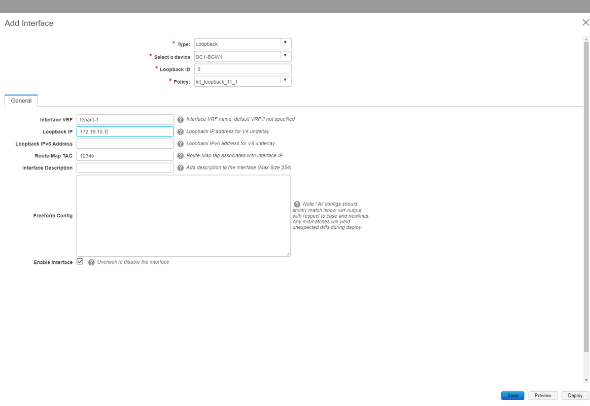
# Same step will have to be done on other 3 Border Gateways.
Step 21: VRFLITE configurations on DCI switches
# In this topology, the DCI Switches are configured with VRFLITE towards the BGWs. VRFLITE is also configured towards the North Of DCI Switches(ie to the Core switches)
# For TRM Purposes, the PIM RP within the VRF tenant-1 is located in the Core Switch which is Connected via VRFLITE to the DCI switches
# This topology has IPv4 BGP neighborship from DCI switches to the Core Switch within VRF tenant-1 that is at the top of the diagram.
# For this purpose, Sub-interfaces are created and assigned with IP addresses and BGP neighborships are established as well(These are Done by CLI directly on the DCI and Core Switches)
DCI-1# sh ip bgp sum vrf tenant-1
BGP summary information for VRF tenant-1, address family IPv4 Unicast
BGP router identifier 10.33.10.2, local AS number 65001
BGP table version is 17, IPv4 Unicast config peers 5, capable peers 5
4 network entries and 10 paths using 1680 bytes of memory
BGP attribute entries [3/504], BGP AS path entries [3/18]
BGP community entries [0/0], BGP clusterlist entries [0/0]

Neighbor        V    AS MsgRcvd MsgSent   TblVer  InQ OutQ Up/Down  State/PfxRcd
10.33.10.1      4 65000    6366    6368       17    0    0    4d10h 2
10.33.10.9      4 65000    6368    6369       17    0    0    4d10h 2
10.33.20.1      4 65002    6369    6368       17    0    0    4d10h 2
10.33.20.9      4 65002    6369    6368       17    0    0    4d10h 2
172.16.111.2    4 65100      68      67       17    0    0 00:49:49 2  # This is towards the Core switch from DCI-1
# Above in red is the BGP neighbor towards the Core switch from DCI-1.
DCI-2# sh ip bgp sum vr tenant-1
BGP summary information for VRF tenant-1, address family IPv4 Unicast
BGP router identifier 10.33.10.6, local AS number 65001
BGP table version is 17, IPv4 Unicast config peers 5, capable peers 5
4 network entries and 10 paths using 1680 bytes of memory
BGP attribute entries [3/504], BGP AS path entries [3/18]
BGP community entries [0/0], BGP clusterlist entries [0/0]

Neighbor        V    AS MsgRcvd MsgSent   TblVer  InQ OutQ Up/Down  State/PfxRcd
10.33.10.5      4 65000    6368    6369       17    0    0    4d10h 2
10.33.10.13     4 65000    6369    6369       17    0    0    4d10h 2
10.33.20.5      4 65002    6370    6369       17    0    0    4d10h 2
10.33.20.13     4 65002    6370    6369       17    0    0    4d10h 2
172.16.222.2    4 65100      53      52       17    0    0 00:46:12 2  # This is towards the Core switch from DCI-2
# Respective BGP configurations are required on the Core switch as well(back to the DCI-1 and DCI-2)
Unicast Verifications
East/West from DC1-Host1 to DC2-Host1
# With all the above configurations pushed from DCNM and manual CLI(Steps 1 through 21), the unicast reachability should be working East/West
DC1-Host1# ping 172.16.144.2 source 172.16.144.1
PING 172.16.144.2 (172.16.144.2) from 172.16.144.1: 56 data bytes
64 bytes from 172.16.144.2: icmp_seq=0 ttl=254 time=0.858 ms
64 bytes from 172.16.144.2: icmp_seq=1 ttl=254 time=0.456 ms
64 bytes from 172.16.144.2: icmp_seq=2 ttl=254 time=0.431 ms
64 bytes from 172.16.144.2: icmp_seq=3 ttl=254 time=0.454 ms
64 bytes from 172.16.144.2: icmp_seq=4 ttl=254 time=0.446 ms

--- 172.16.144.2 ping statistics ---
5 packets transmitted, 5 packets received, 0.00% packet loss
round-trip min/avg/max = 0.431/0.529/0.858 ms
North/South from DC1-Host1 to PIM RP(10.200.200.100)
DC1-Host1# ping 10.200.200.100 source 172.16.144.1
PING 10.200.200.100 (10.200.200.100) from 172.16.144.1: 56 data bytes
64 bytes from 10.200.200.100: icmp_seq=0 ttl=250 time=0.879 ms
64 bytes from 10.200.200.100: icmp_seq=1 ttl=250 time=0.481 ms
64 bytes from 10.200.200.100: icmp_seq=2 ttl=250 time=0.483 ms
64 bytes from 10.200.200.100: icmp_seq=3 ttl=250 time=0.464 ms
64 bytes from 10.200.200.100: icmp_seq=4 ttl=250 time=0.485 ms

--- 10.200.200.100 ping statistics ---
5 packets transmitted, 5 packets received, 0.00% packet loss
round-trip min/avg/max = 0.464/0.558/0.879 ms
Multicast Verifications
For this document purpose, the PIM RP for the "tenant-1" VRF is configured and present external to the VXLAN Fabric; Per the topology, the PIM RP is configured on Core switch with the IP address-> 10.200.200.100
Source in Non-vxlan(behind Core Switch), Receiver in DC2
Refer Topology which is shown at the beginning.
# North/South Multicast traffic sourced from Non-VXLAN host-> 172.17.100.100, Receiver is Present in both Datacenters; DC1-Host1-> 172.16.144.1 and DC2-Host1-> 172.16.144.2, Group -> 239.100.100.100
Legacy-SW#ping 239.100.100.100 source 172.17.100.100 rep 1
Type escape sequence to abort.
Sending 1, 100-byte ICMP Echos to 239.100.100.100, timeout is 2 seconds:
Packet sent with a source address of 172.17.100.100

Reply to request 0 from 172.16.144.1, 3 ms
Reply to request 0 from 172.16.144.1, 3 ms
Reply to request 0 from 172.16.144.2, 3 ms
Reply to request 0 from 172.16.144.2, 3 ms
Source in DC1, Receiver in DC2 as well as external
DC1-Host1# ping multicast 239.144.144.144 interface vlan 144 vrf vlan144 cou 1
PING 239.144.144.144 (239.144.144.144): 56 data bytes
64 bytes from 172.16.144.2: icmp_seq=0 ttl=254 time=0.781 ms       # Receiver in DC2
64 bytes from 172.17.100.100: icmp_seq=0 ttl=249 time=2.355 ms     # External Receiver

--- 239.144.144.144 ping multicast statistics ---
1 packets transmitted,
From member 172.17.100.100: 1 packet received, 0.00% packet loss
From member 172.16.144.2: 1 packet received, 0.00% packet loss
--- in total, 2 group members responded ---
Source in DC2, Receiver in DC1 as well as external
DC2-Host1# ping multicast 239.145.145.145 interface vlan 144 vrf vlan144  cou 1
PING 239.145.145.145 (239.145.145.145): 56 data bytes
64 bytes from 172.16.144.1: icmp_seq=0 ttl=254 time=0.821 ms       # Receiver in DC1
64 bytes from 172.17.100.100: icmp_seq=0 ttl=248 time=2.043 ms     # External Receiver

--- 239.145.145.145 ping multicast statistics ---
1 packets transmitted,
From member 172.17.100.100: 1 packet received, 0.00% packet loss
From member 172.16.144.1: 1 packet received, 0.00% packet loss
--- in total, 2 group members responded ---
Contributed by Cisco Engineers
- Varun JoseTechnical Leader-CX
Contact Cisco
- Open a Support Case

- (Requires a Cisco Service Contract)
 Feedback